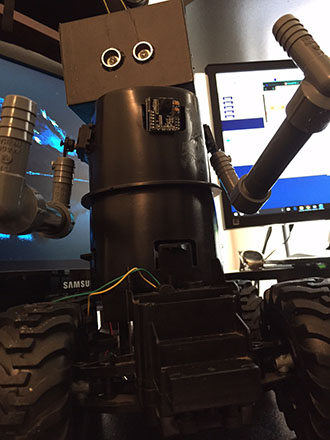
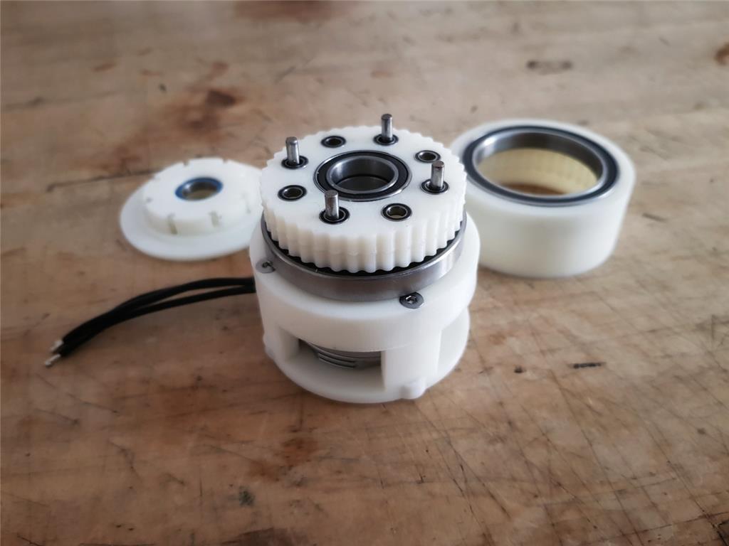
This is a WIP of a cycloidal gearbox with a reduction ratio of 40:1. It is driven by a Tarot 4108 brushless motor, in theory it should have almost zero backlash...
By Mickey666Maus
— Last update
Other robots from Synthiam community
Dunning-Kruger's How To Use Roborealm For Indoor Navigation
Ok, so I finally sat down to look at what RoboRealm can actually do other than just face and object recognition.... I...
Kab's Ogie The Bear In Action
www.facebook.com/kabartstudio/videos/882456251867419/ Finally finished making Ogie the talking bear with the EZ Robot...
Bhouston's My New Robot
Heres a short video introducing my new robot. Thanks for everyones help to get this far with it.
Awsome. Looking forward to your progress on this. Do you know what your final torque will be when you on complete?
There is a lot of math behind it that I really do not understand. But I guess from kv value of your brushless motor, you can calculate the torque constant.
https://www.fxsolver.com/solve/
So the Tarot S 4108 should have a torque constant of 0.02512 Nm/A
Also you can calculate the revolutions per volt applied... The Tarot S 4108 has 380 rpm/volt or 39.79(rad/sec)/volt There is an online converter for this! https://lucidar.me/en/unit-converter/rad-per-second-to-revolution-per-minute/
So once the gearbox is working I will need to measure the amps the motor draws under load, but lets consider 2.5Amps... 0.029 * 2.5 = 0.0628Nm
By multiplying a gear ratio of 40, the ideal torque on the output is 0.0628*40 = 2.512Nm
But I really don't know much about all this...so please if anyone here knows better correct me before I blow up the next Power Supply!!
Interesting I tried the Chinese to english translator but it didn't work. WTF:p
Great job and that looks like mine. I have some bearings on order because I has to use ones that were 'closeish' on my first prototype. Interested to see how this goes. If you don't mind I will plop a few pics in this thread. Just an interesting side note here. I had a college prof ask me about how much torque a Newton meter is. I had no idea. He told me that a newton was equal to an apple. So imagine holding an apple on a 1 meter weightless stick. Remembered that all these years.
Have you guys ever seen this from James Bruton? I’ve seen real commercial products of elastic actuators recently and they’re really great.
Something like this can be 3d printed and use 2 springs. One on either side... I got it from this document: prismatic-sea-paine.pdf
@Perry_S yes please!!!
Actually I thought, I'll just throw my actuator in this thread to start the discussion!!
I got it working now, but the vibration is really heavy...lets see if I can reduce it some more!
What were your issues?
I will put together some links for Cycloidal Gearboxes that I used to build mine...
Which CAD software are you using?
I will upload all the .stl files once I got that gearbox ready!
@DJSures that looks great!! I am also following quiet a few quadrupets, James Bruton has two versions that he is currently working on...seems like elastic actuators are a big deal, when it comes to building a walking robot!! Super interesting!!!
Well - yes, walking robots can benefit from elastic actuators. However, I can see how they can be used for al joints and replace servo motors. I can envision a modular design that can replace a servo using an elastic actuator with a spring for the force measurement.
Nice!! I would jump right in and print one!! Looking forward to see what you are having in mind!! It would be great to have a robot that can adjust the force according to what is actually needed!! Great idea!!
@DJ - I have watched James Brutton for quite some time and I find his work highly interesting. I start to lose interest when his builds turn ultra high dollar. I like the 3D printed stuff but now he just throws O-Drives at problems like they are free. If you note the evolution of his robot dogs the only one that walks is the one that uses standard servos. Can't fault him though as he puts out great videos at an astonishing pace.
@Mickey - The problem I had with cycloidals is the vibration. You see from how they are put together that the cam that drives the process of the motor is inherently not balanced. There are two stage ones that try to fix that but as a rotating assembly they are not ideal.
Perry - how do you feel about the elastic actuators? Is that something you'd see a use for? To easily recognize force?
Ha,that is exactly how I feel about James Brutton...he is really talented and a great builder. But you get the feeling, that since he needs to keep his patreons entertained, he is just constantly producing content, without really trying to solve things beforehand! But then again, you can see him failing and progressing...which is also a nice thing!! Anyways, there should be more content like the one that he puts out...great channel!!
If you take a closer look at my reducer, you can see that it is a dual cycloidal disk driving the output...the disks are set to opposing sides, so the center of mass always stays in the middle! Still vibration is quiet high...
I think there is another problem with the output shaft, that I need to fix...I will have to wrap my head around it, and look at a few other projects. Hope I can get it done!!
I made a quick showcase of the actuator...it is very noisy and has a lot of vibration! I had to change Dongil Chois original design because I am using a different motor. And am not sure if a printed Cycloid Gearbox just sounds like this, or if there is too much friction caused by the eccentric shaft? There might also be too little space between the disks so the torque twist makes them collide?
Any ideas on what to improve?
Or am I on the wrong path here...
@Mickey666Maus I have been looking into cyclodial GearBoxes since you introduced us to them, it seems that yours has the least vibration of all the ones I have seen. on a robot they only activate for short periods of time, so it is not as bad. Robots are noisy anyway. I saw one that uses a tooth belt as the top gear and it is quieter. I figure if it has more power in a small package it may still be worth while. persuing.
I might also try a double stage Cycloidal Gearbox or different reduction ratios...lets see if it makes a difference!
The one with the toothbelt might have been a Harmonic Reducer, also called Strain Wave Reducer...this would be the optimal robotic gearbox, but I never found someone managing to design one that is 3D printable!
The gearbox needs a lot of bearings, but let me know if you would like to print one, and I will upload the .stl files!!
Here is another Strain waved Reducer that I have been looking at it is printed with PETG. https://hackaday.io/project/120377-3d-printed-strain-wave-gear What is your thoughts on this.
Good find!! I will take a look!!
This is another take on a strain wave gear, it works with a belt! I am not sure if this is the better choice over a printed one...but it would surely offer all the needed material properties needed for that part!
This is a nice take a a 3d printed strain wave gear, but seeing the noise and vibration makes me afraid that it might be better to stay within the cycloidal realm of gearboxes?
What do you guys think?
So I got the gearbox setup with the encoder working...it is actually less vibration than expected, I will make more stress tests under load!
Looking good so far!!
Also ARC integration is super easy!!
Nice job! What did you print your parts with?
Its all ABS...
What was the approximate cost for the parts?
Looking forward to your torque testing.
I used an Odrive and the recommended controller from their site...
The motors and bearings were ordered from China, do quiet cheap but as we all know...its a waiting game!!
I think the cost should be less than 150 per joint!!
But a 3d printed gearbox still is a 3d printed gearbox after all...lets see how it'll hold up during some stress tests!!