


-635353562186322812.png)


Hi all,
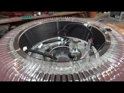
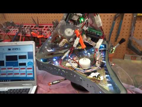
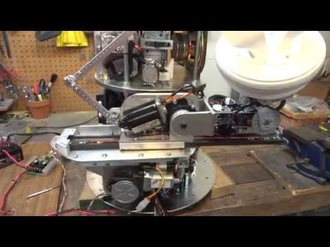
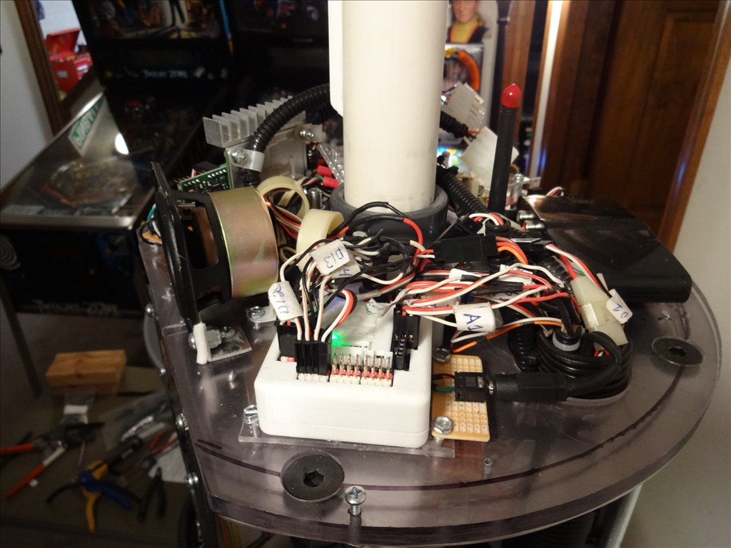
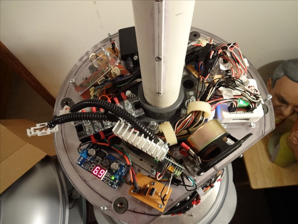
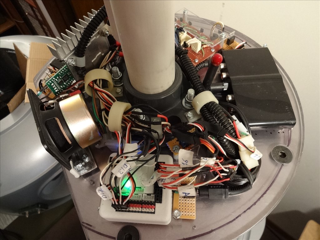
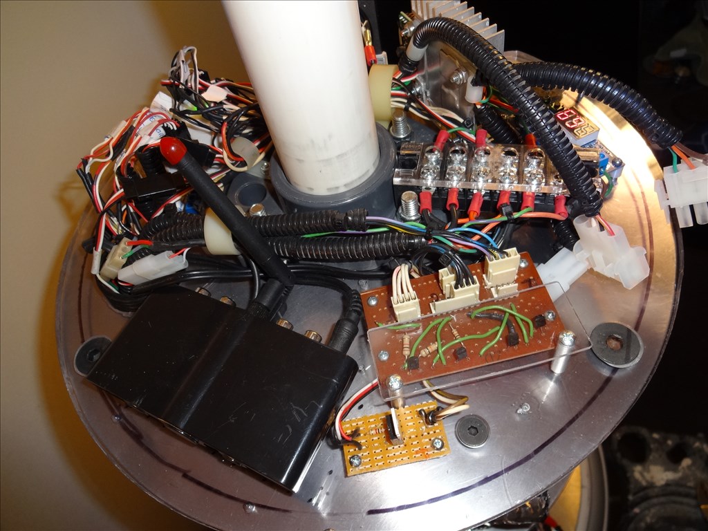
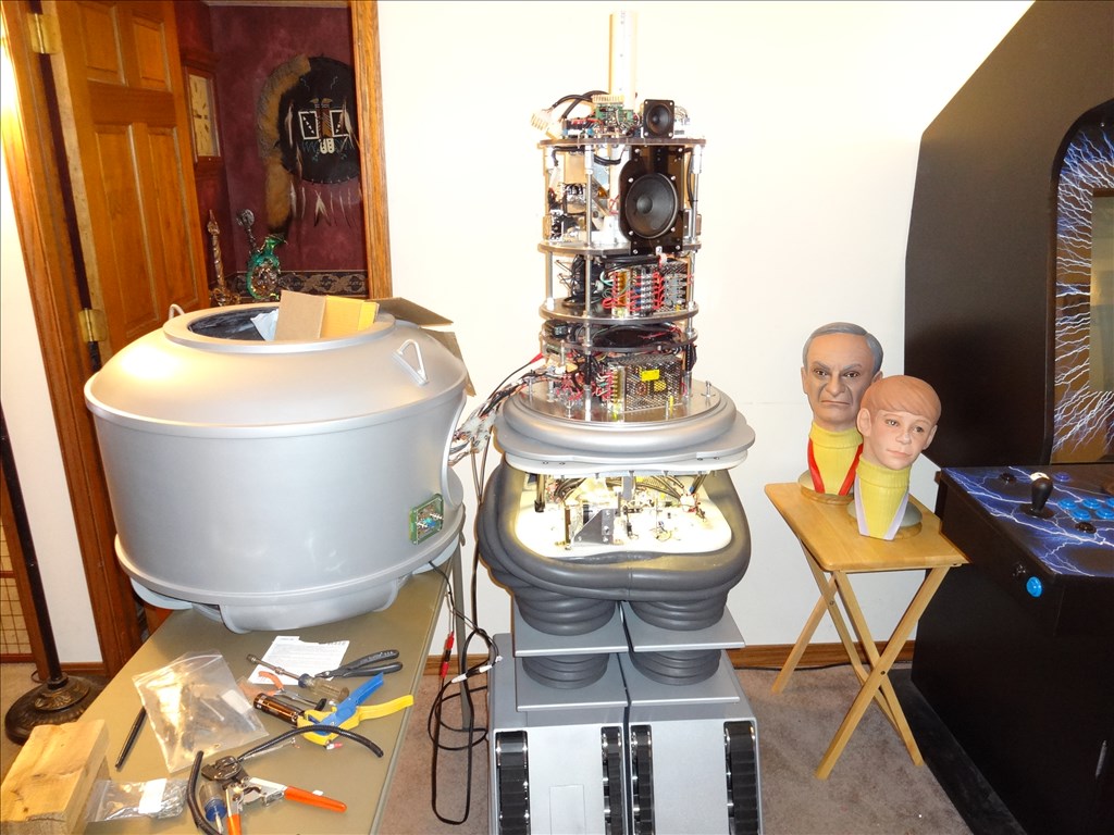
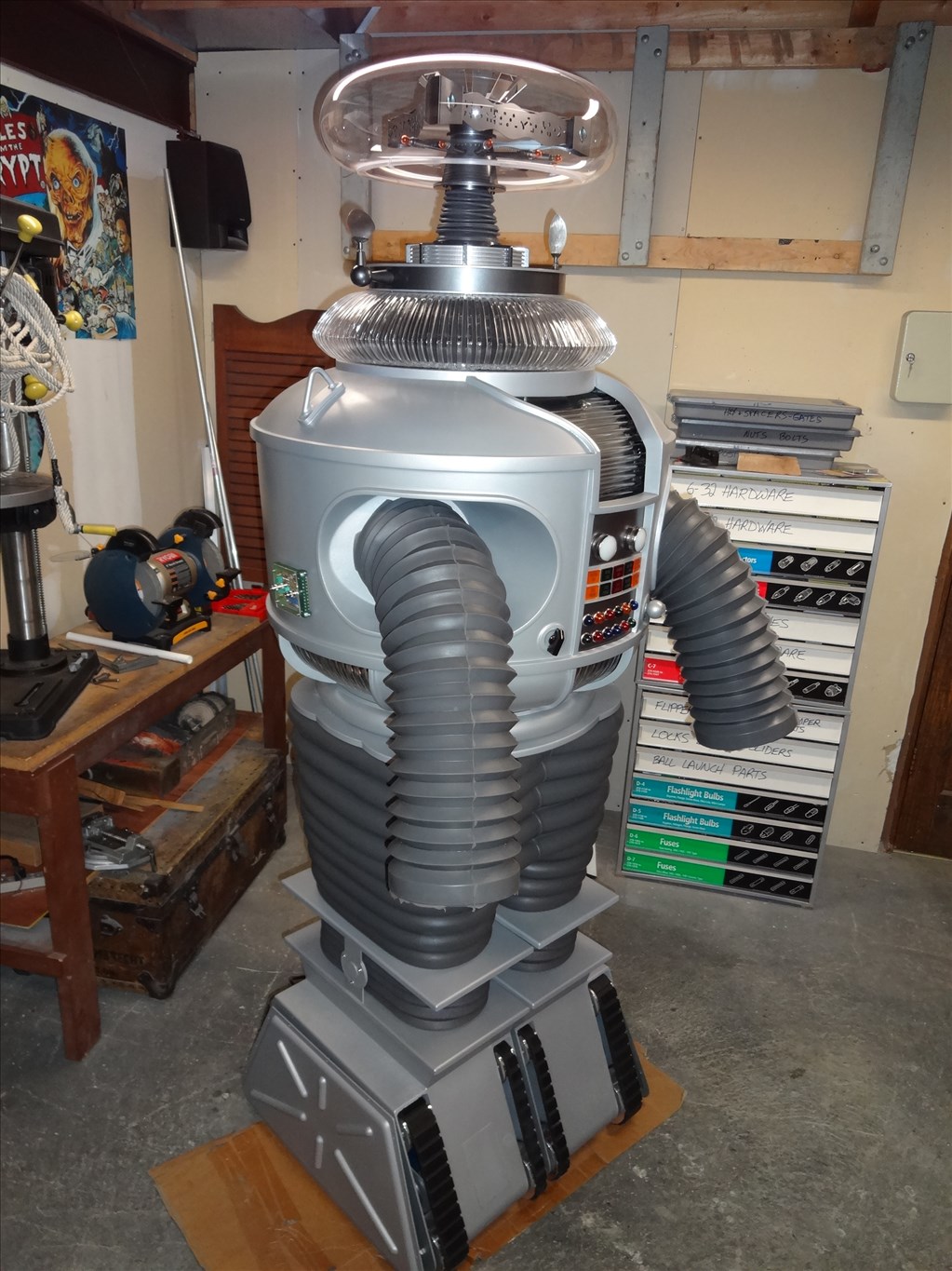
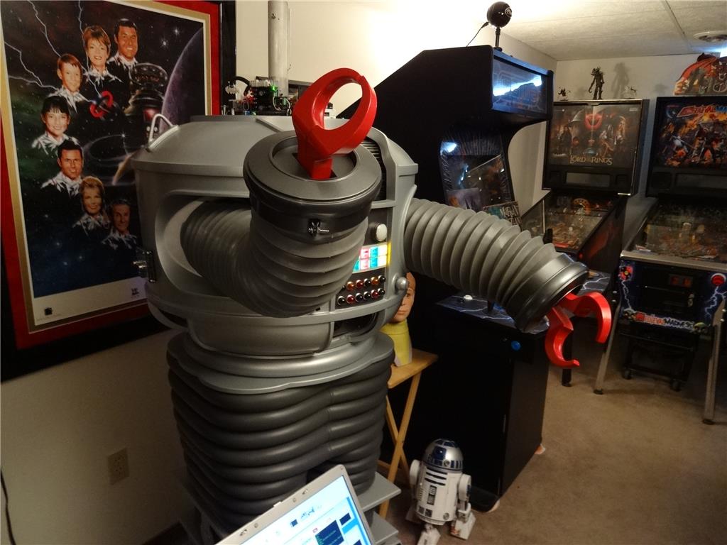
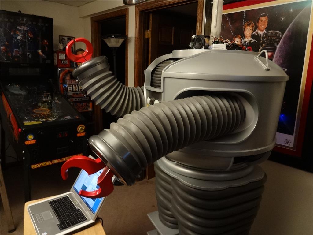
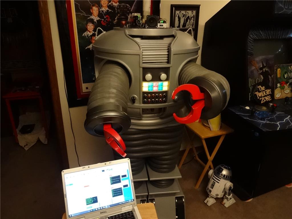
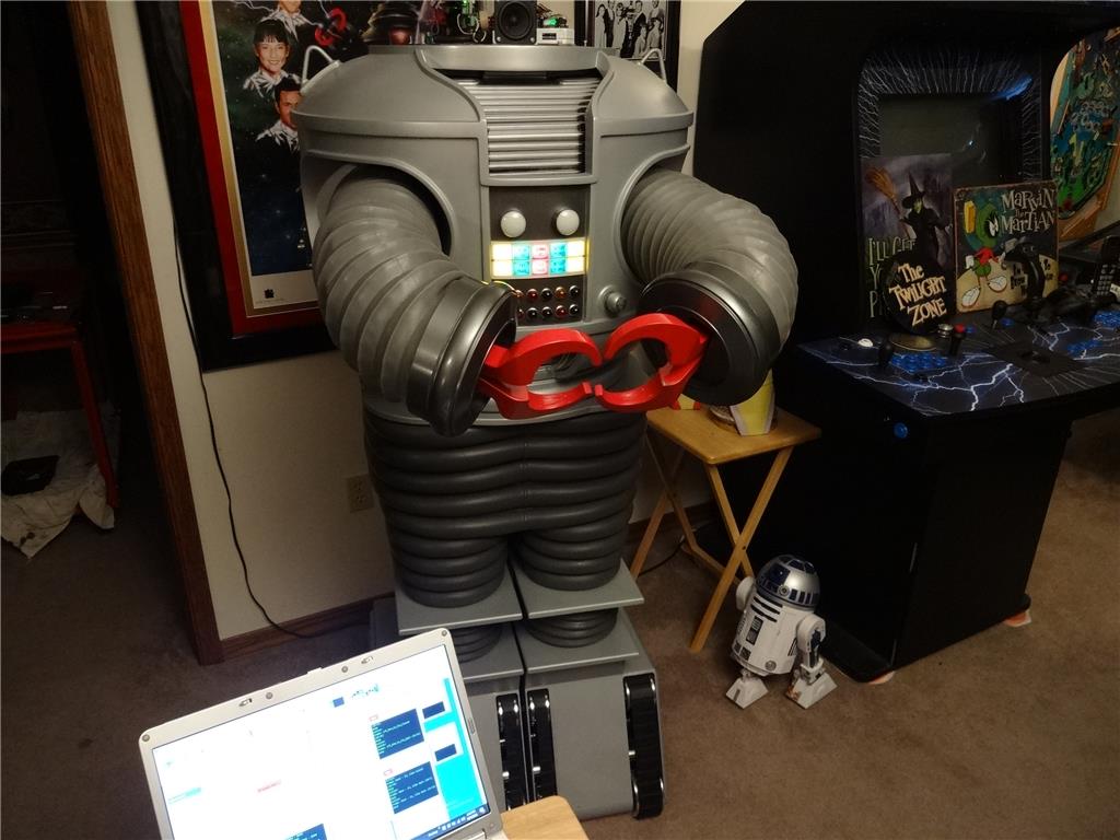
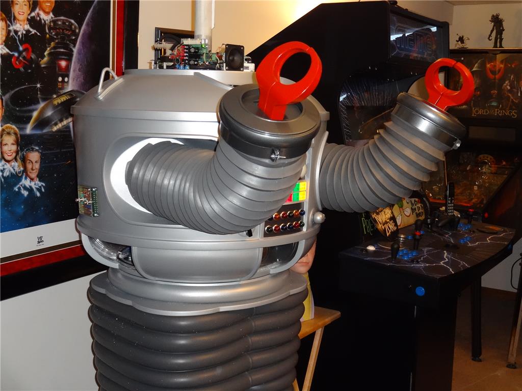
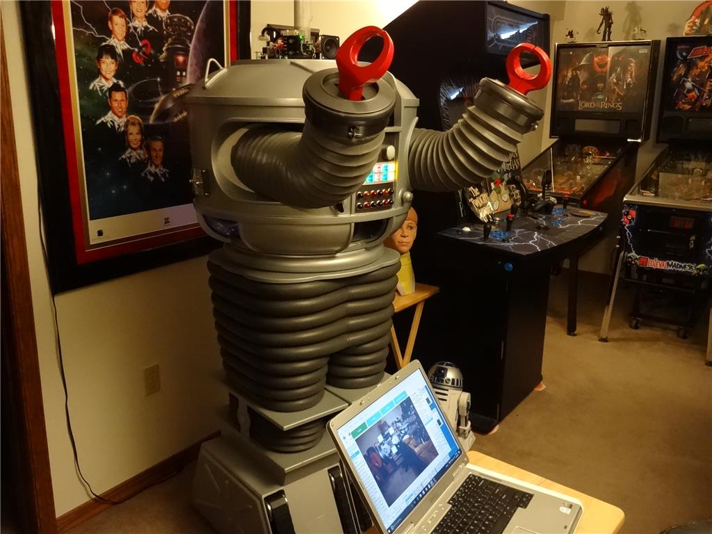
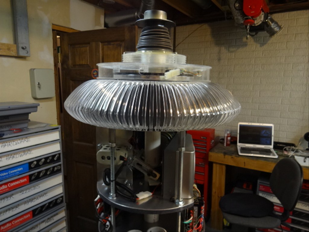
I'd like to share a video I just took of my full size Lost in Space B9 robot that's controlled by two EZ-B controller boards. Right now they are controlling limited movement and voice response of a few motors, lights and sound files played from a Sparkfun MP3 Trigger board. Although I'm just starting with the animation and have more building on the actual robot the result (mostly thanks to the EZ Robot controller board) is shocking. Please have a look at this (4 minute) You Tube vid and enjoy.
Please excuse some Technical camera lighting and sound issues. This is the first time I'd made and posted a vid online.
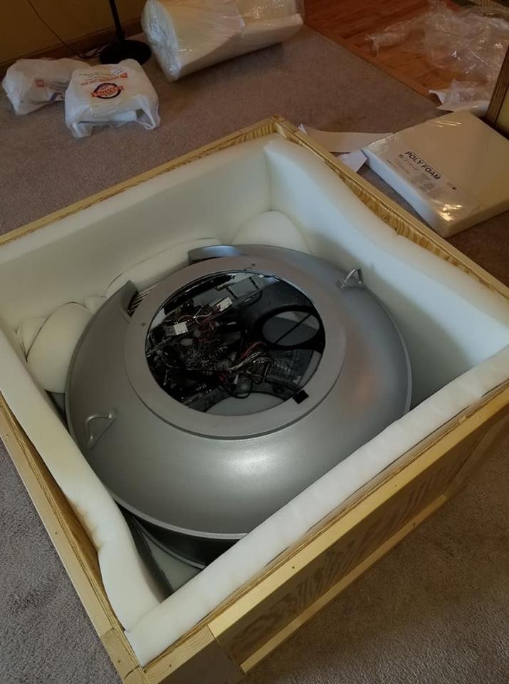
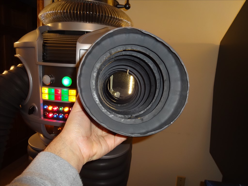
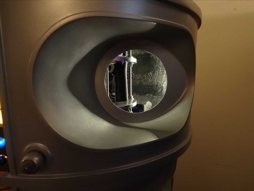
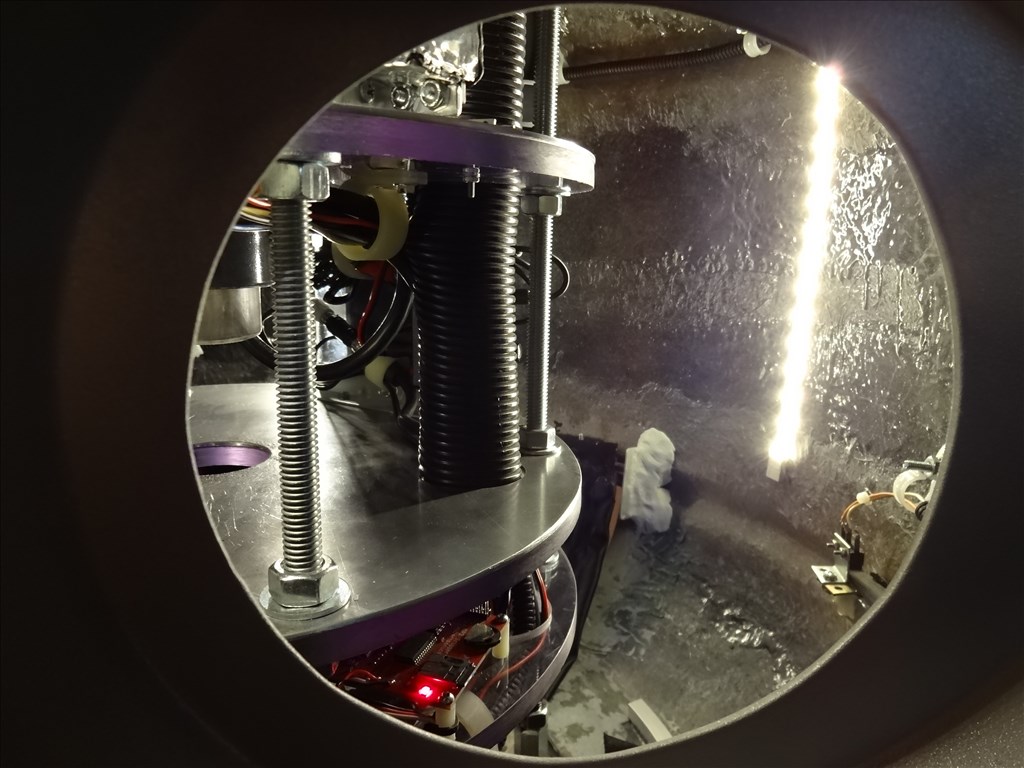
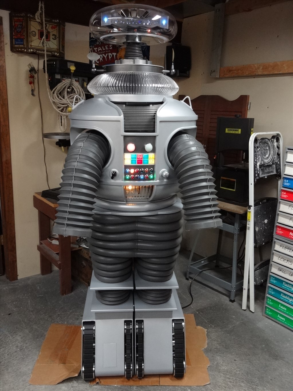
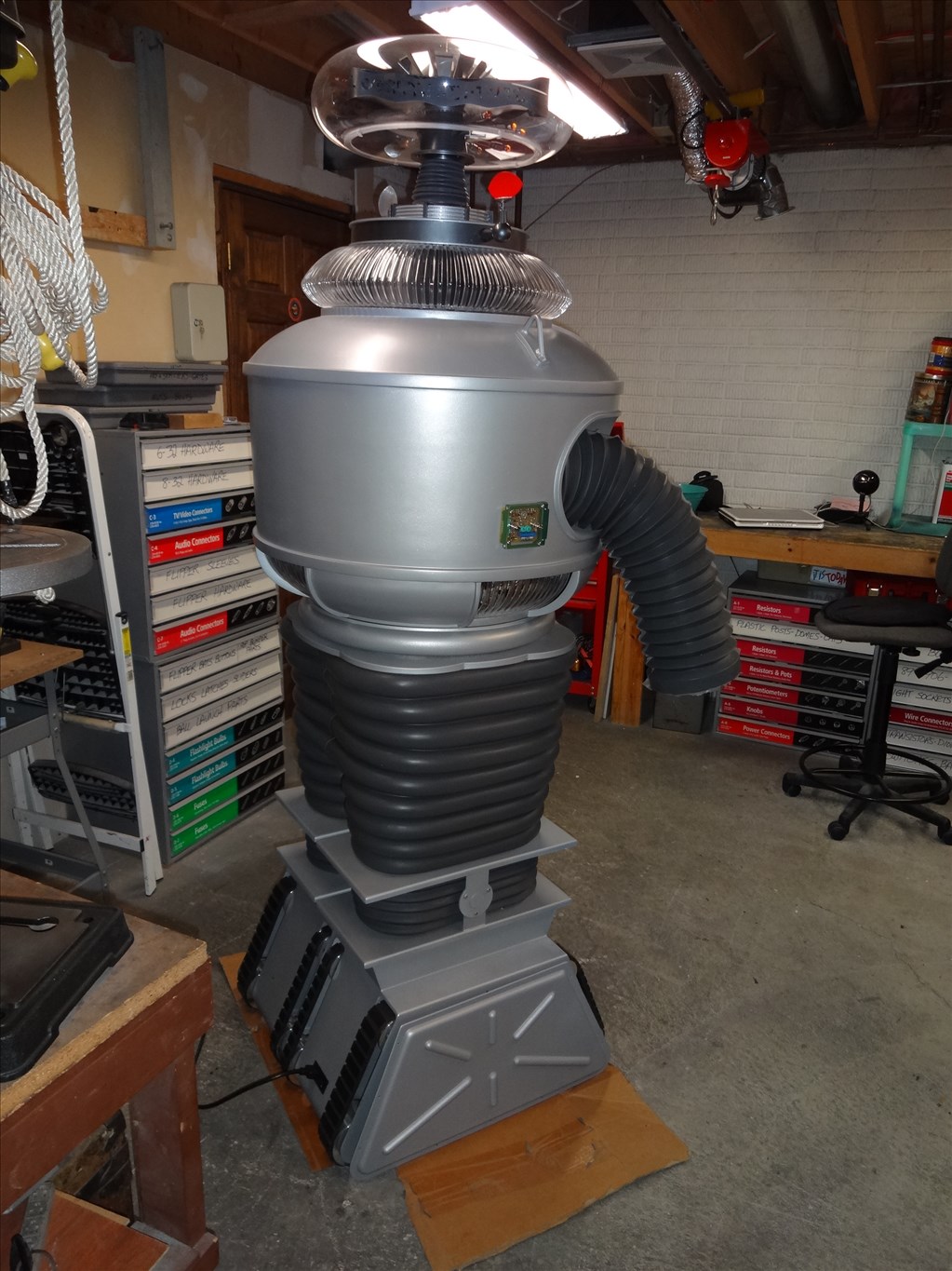
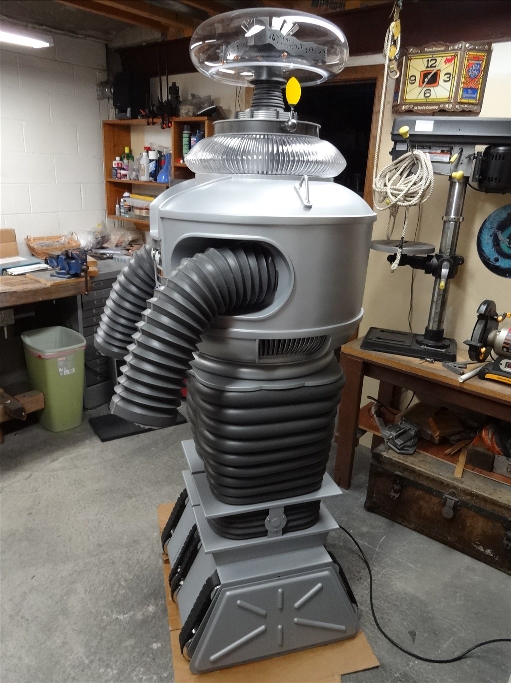
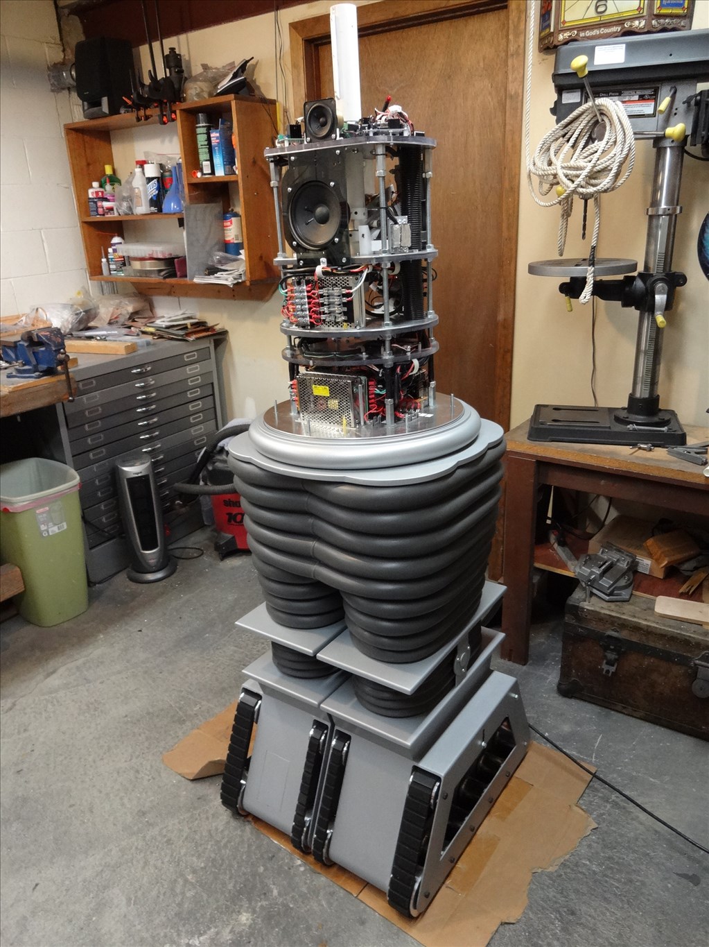
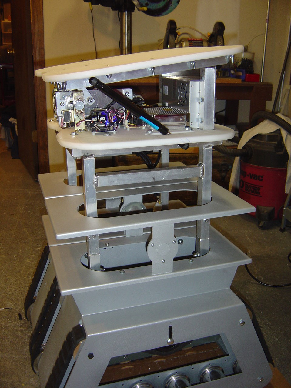
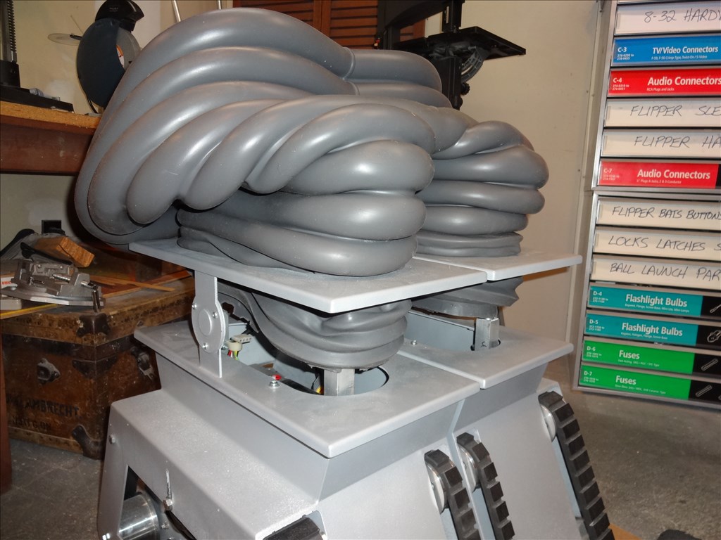
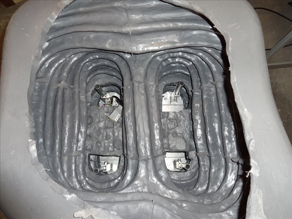
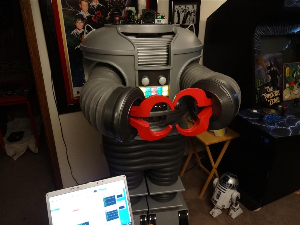
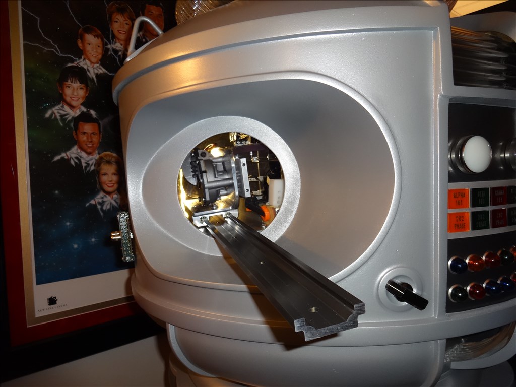
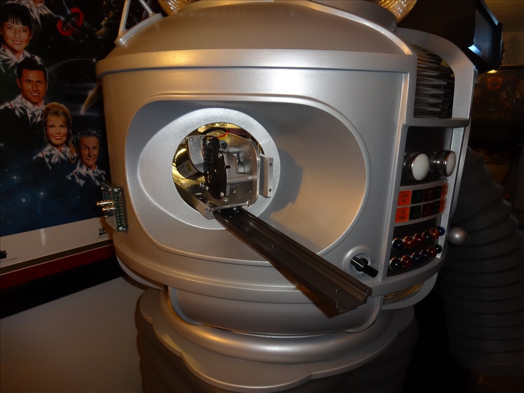
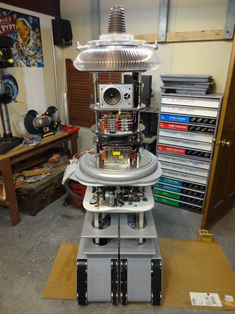
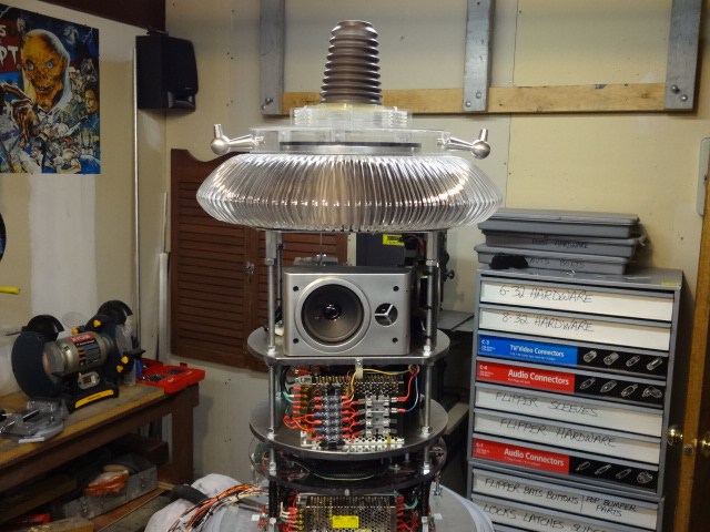
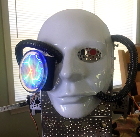
EDIT 8/2/13: Just realized I have no good pictures of how my B9 will look when complete. Here's one of the actual TV robots from the 60's TZ show Lost in Space and one recent shot of where I'm at with my build over 1 1/2 year after I started. Enjoy:


Thanks, Dave Schulpius
Discover more robots
Ezang's The Borg - Resistance Is Futile, You Will Be...

DJ's Spider Robot


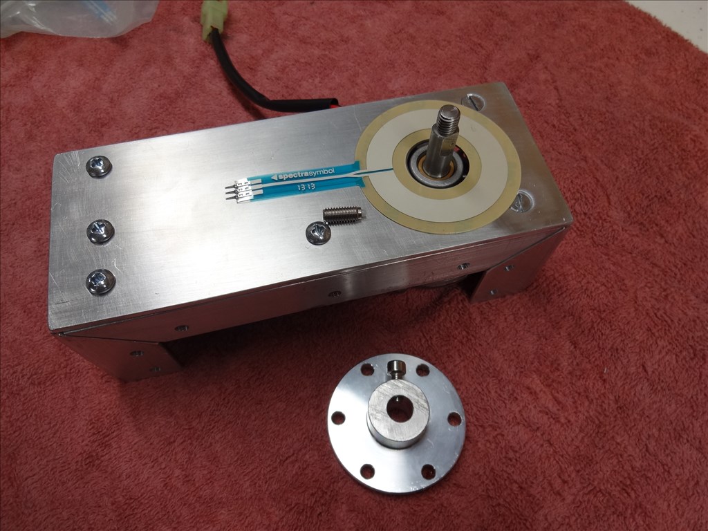
@dave. I wish I could give a definate answer. My guess is that it depends on the application. I believe that the resistance changes as a total across the entire strip. It can't decern an angle of the bend. Imagine a single bend verses a double bend in a long strip. I would buy one and see if it works for you. I did the "buy and test" method with EL lights. I bought wire, tape and panel and found that wire wouldnt work well for me on making straight lines. The light really accentuates any little kink in it. I've found that tape looks so much better. On the flip side of course, wire is better for curvy lines. I look forward to seeing how the flex sensors work for you. I've never seen it in action.
Just to add to the flex sensor discussion, I have not tried them yet but I read some reviews. A few people stressed that you need to support the ends, especially the end with the wires, from flexing or they will break. They also suggested two per axis. They are designed to go in one direction. They will bend backwards without damage but are not as accurate in that direction. By having them in pairs facing each other you can read the one that is going the proper way. I am a little ways away from trying them but I would be curious to see if anyone here has any success with them.
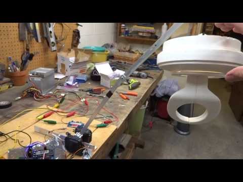
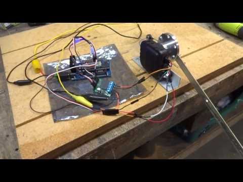
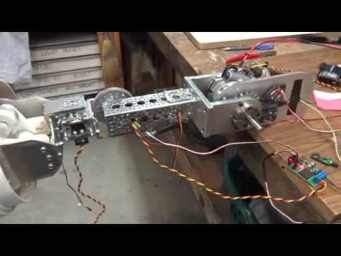
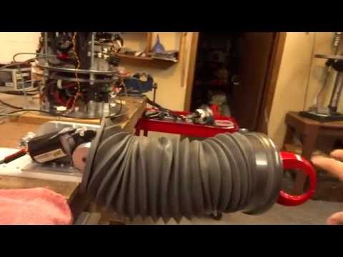
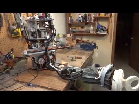
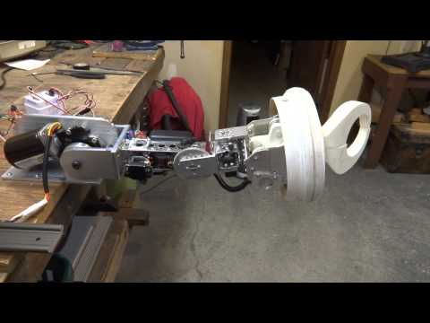
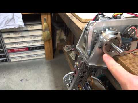
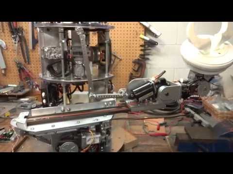
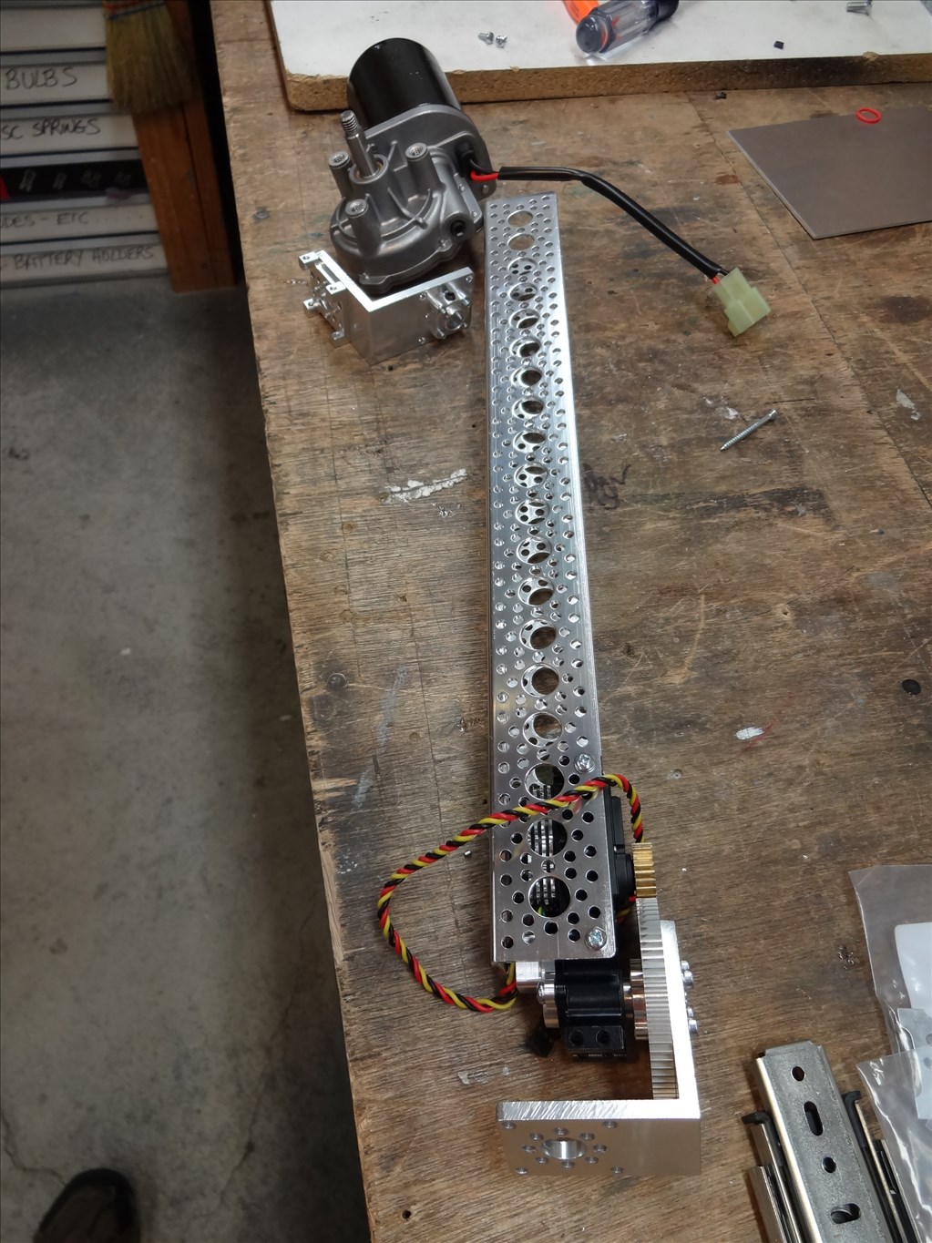
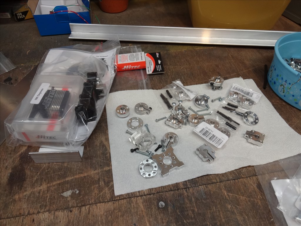
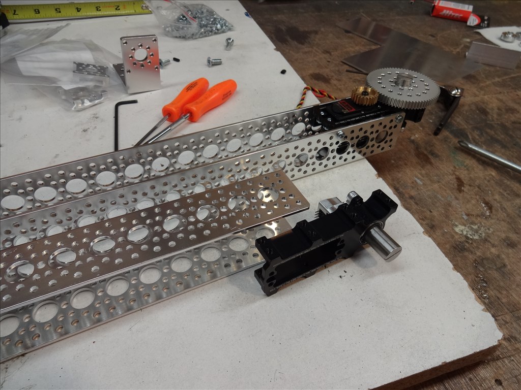
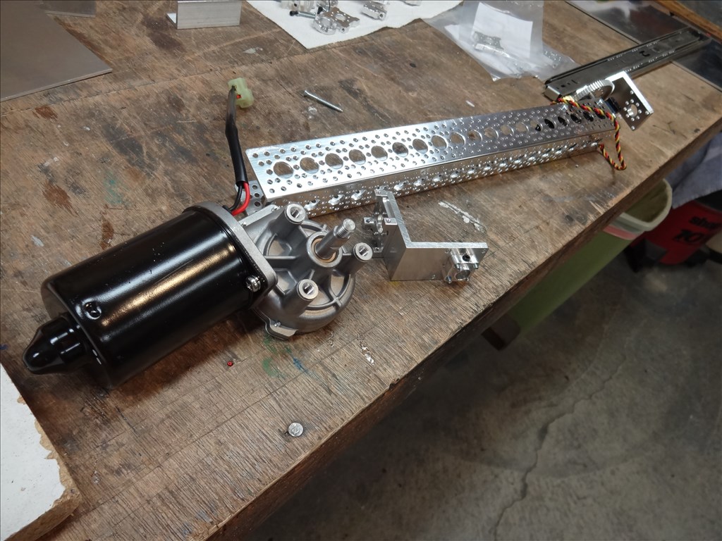
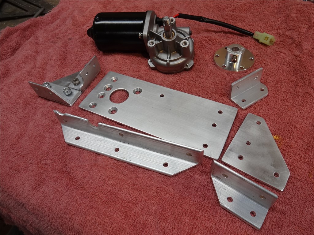
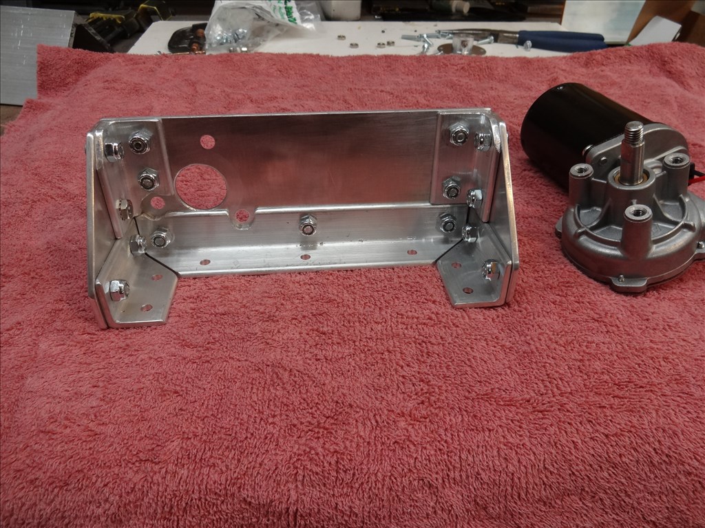
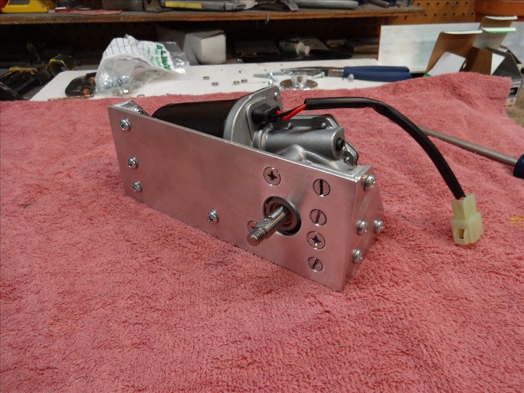
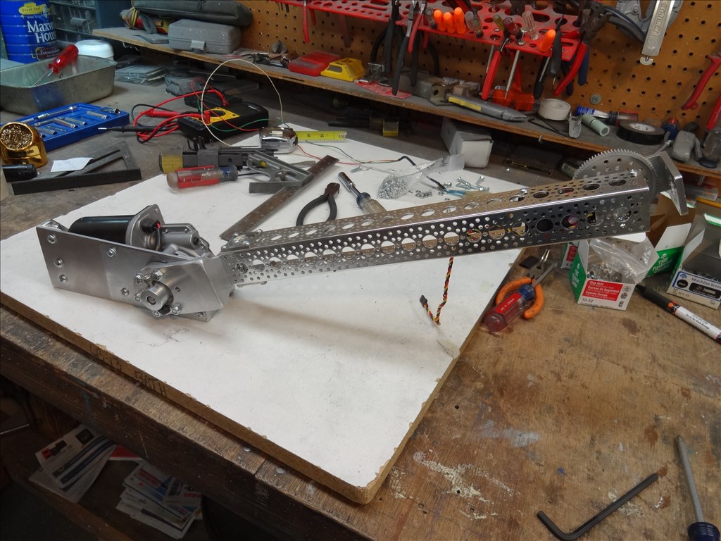
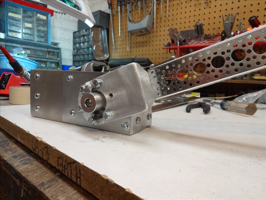
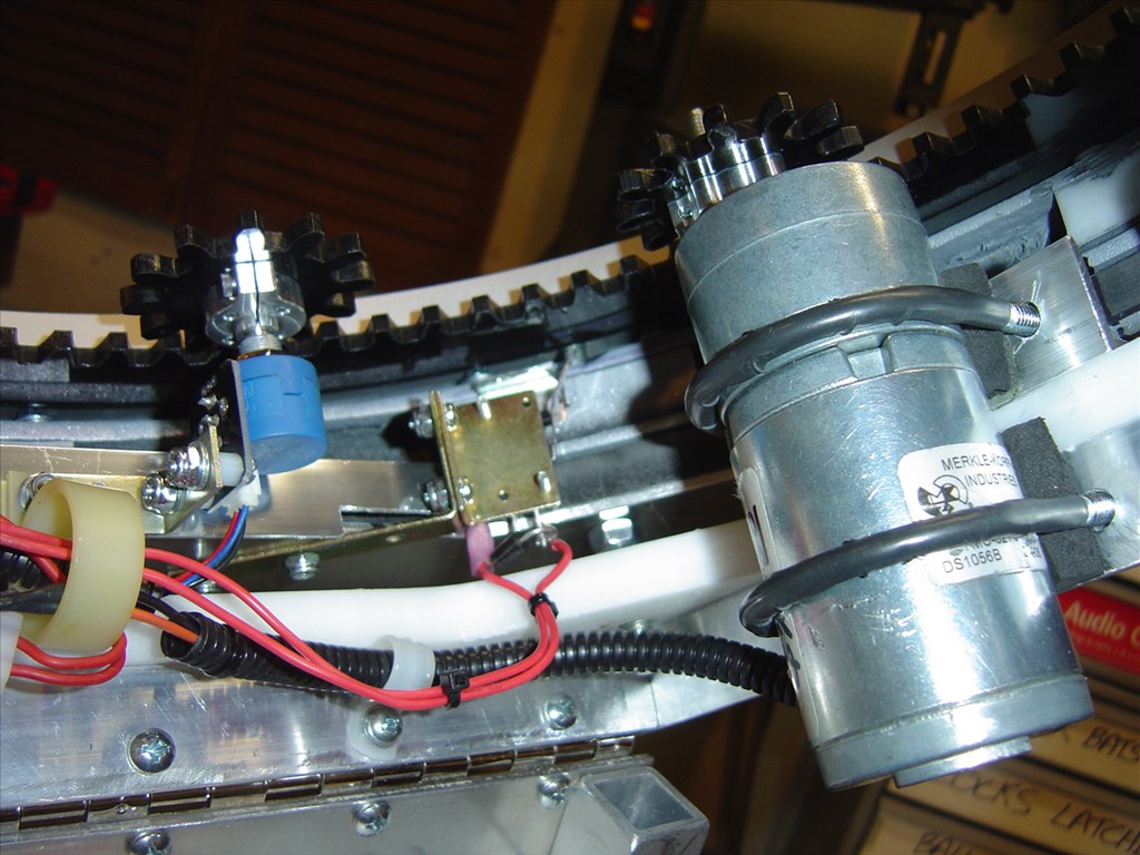
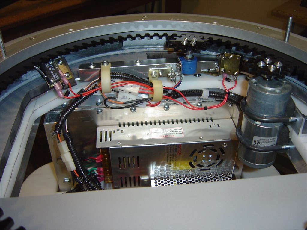
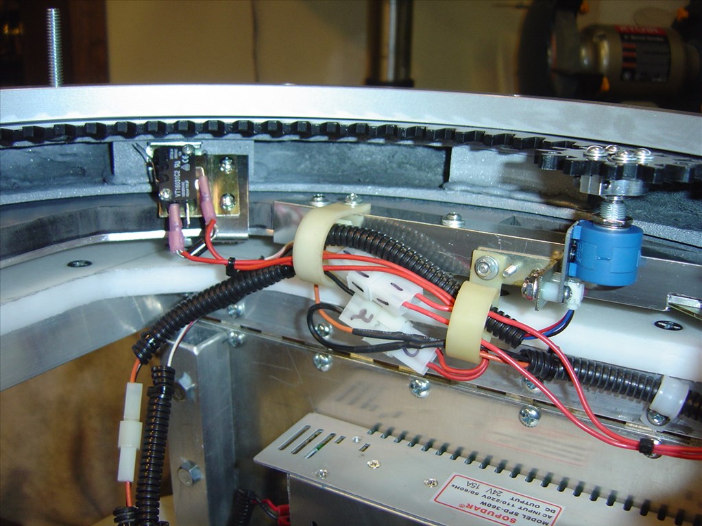
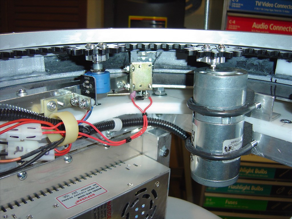
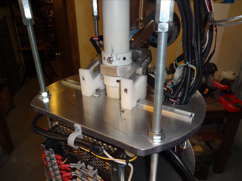
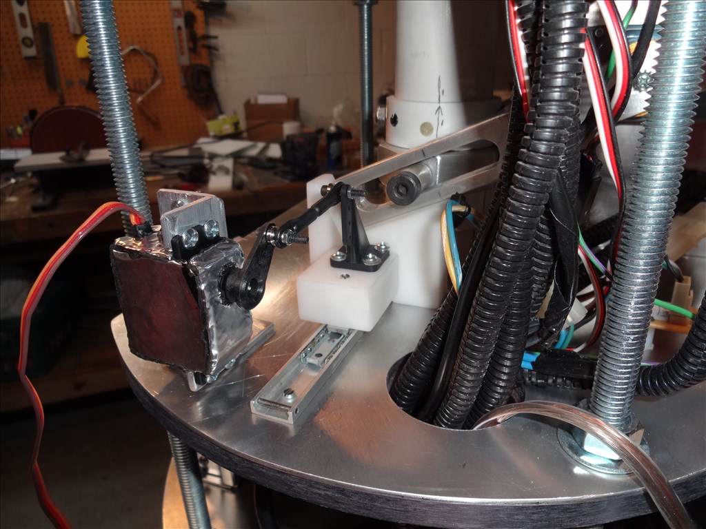
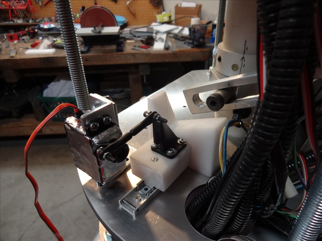
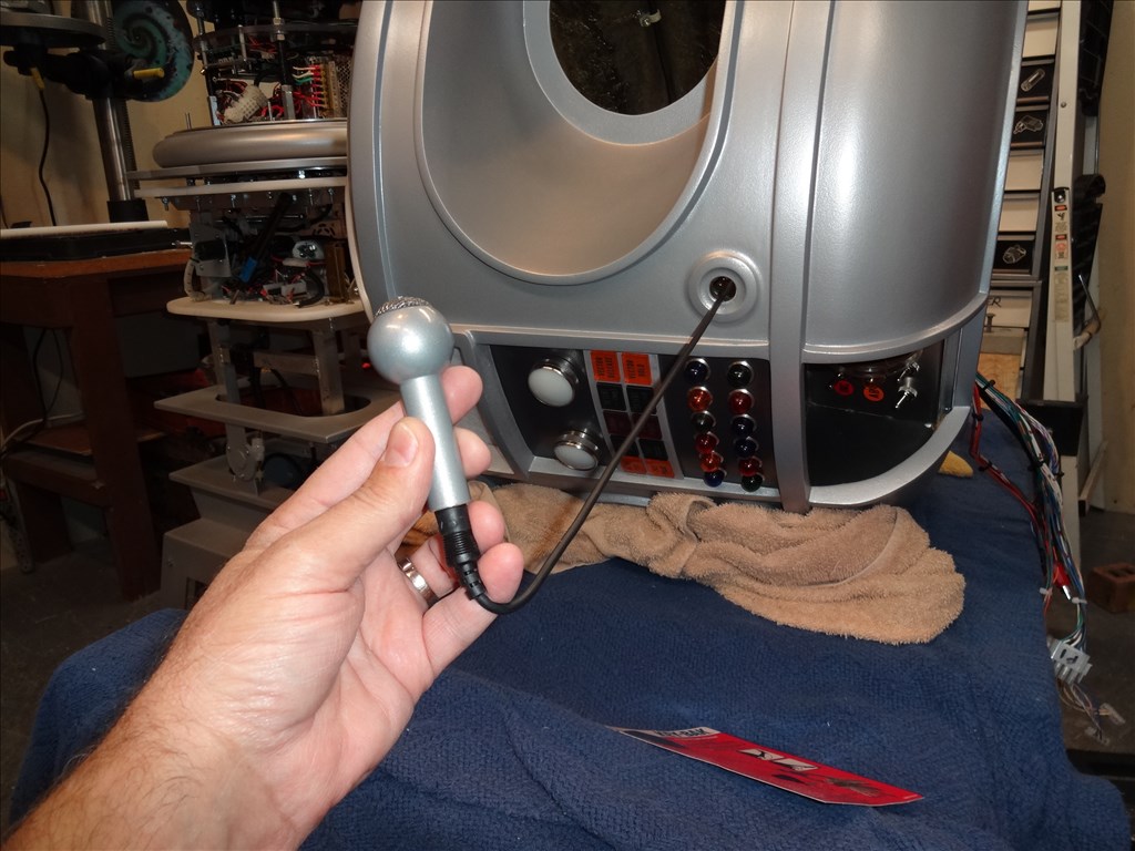
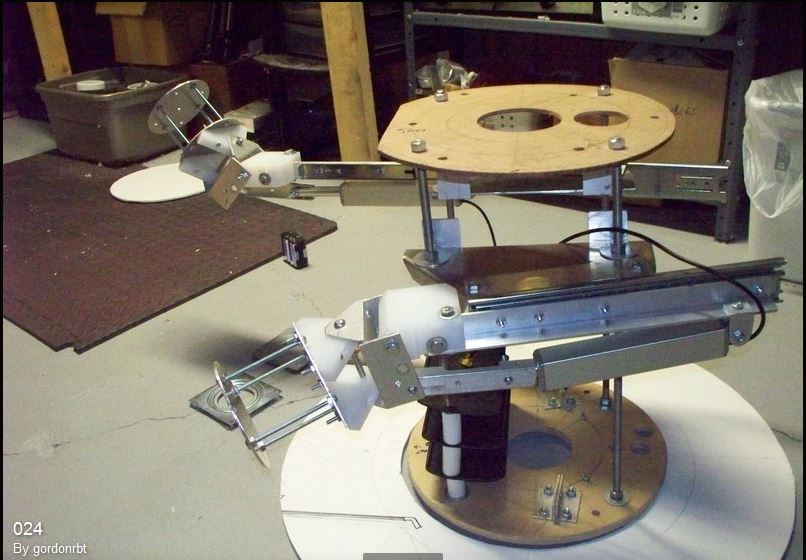
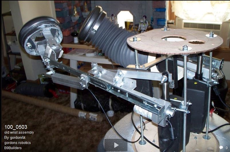
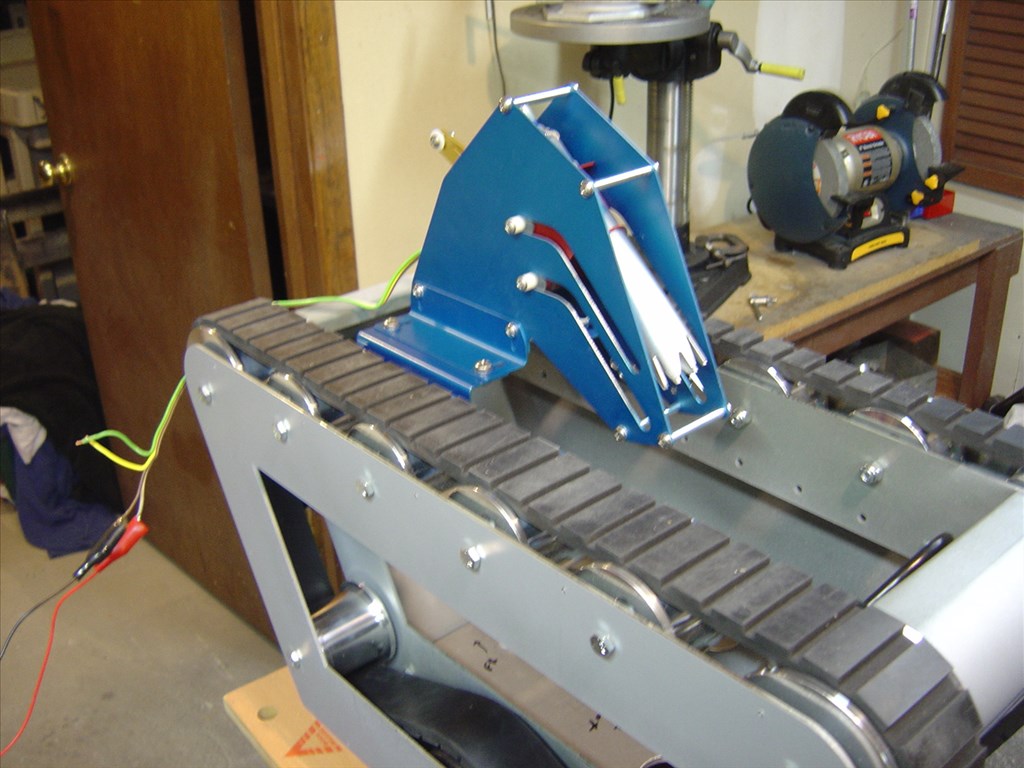
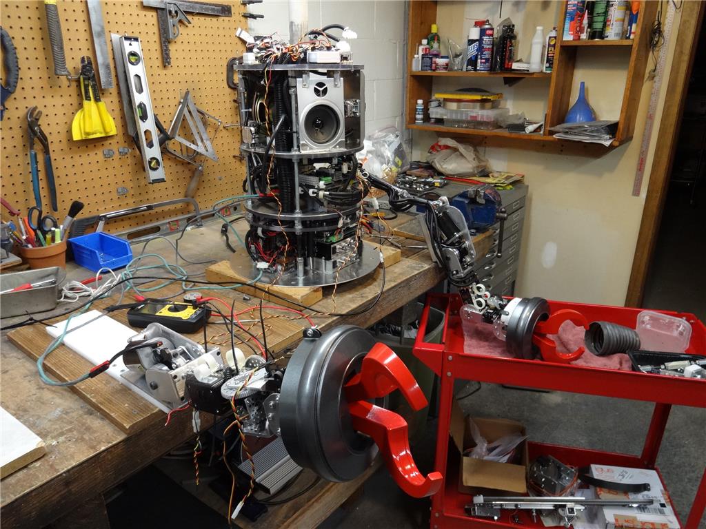
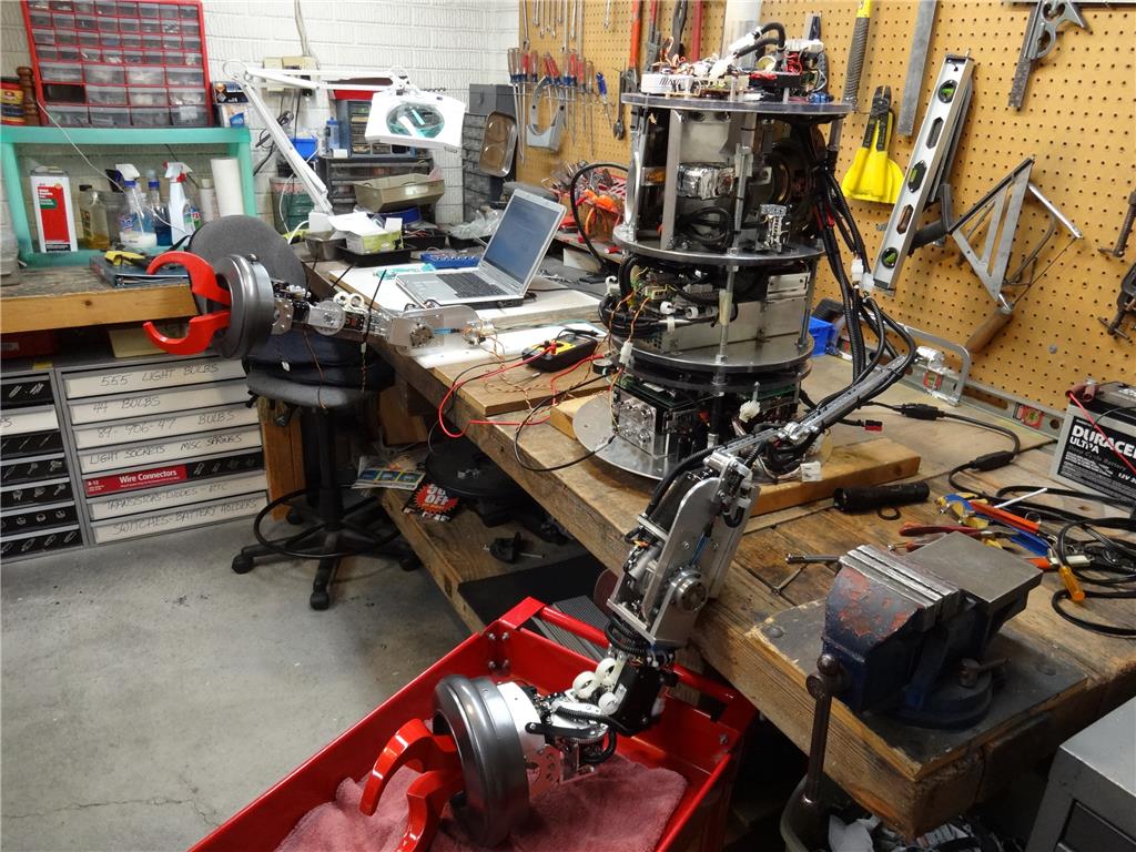
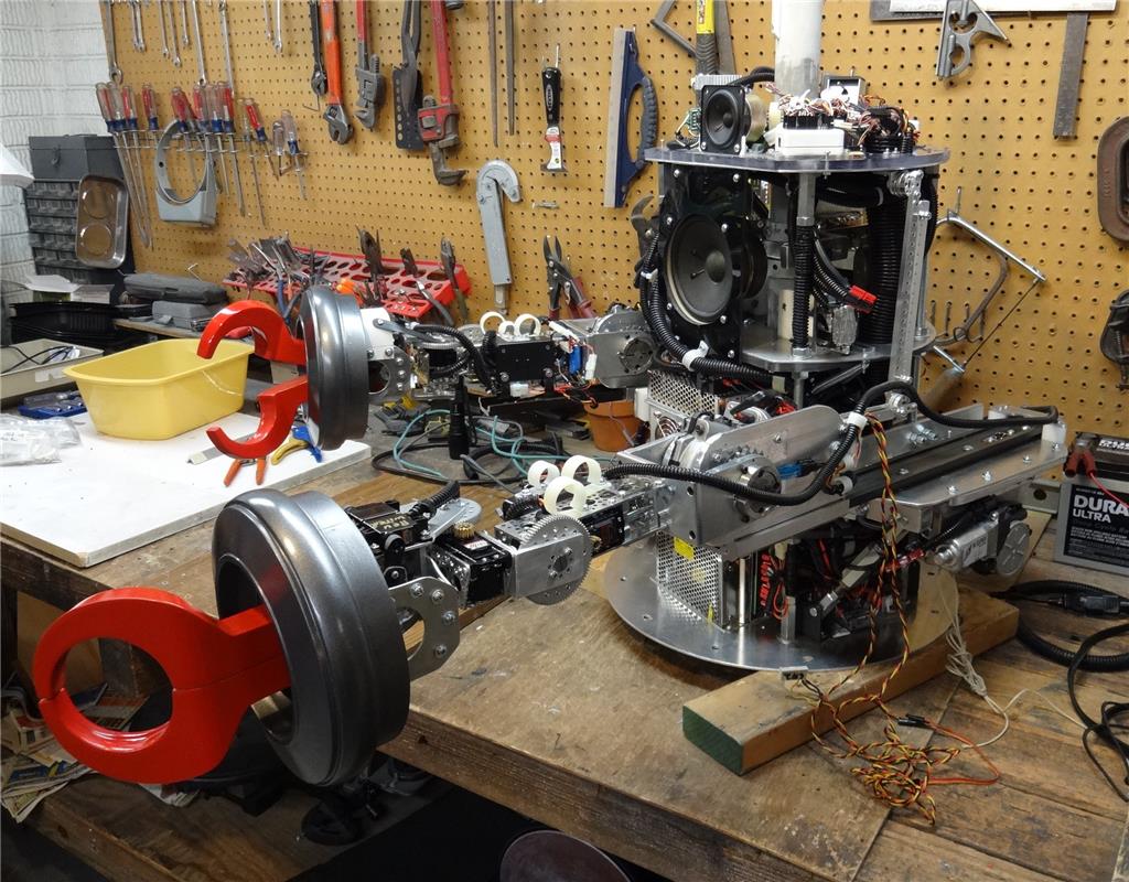
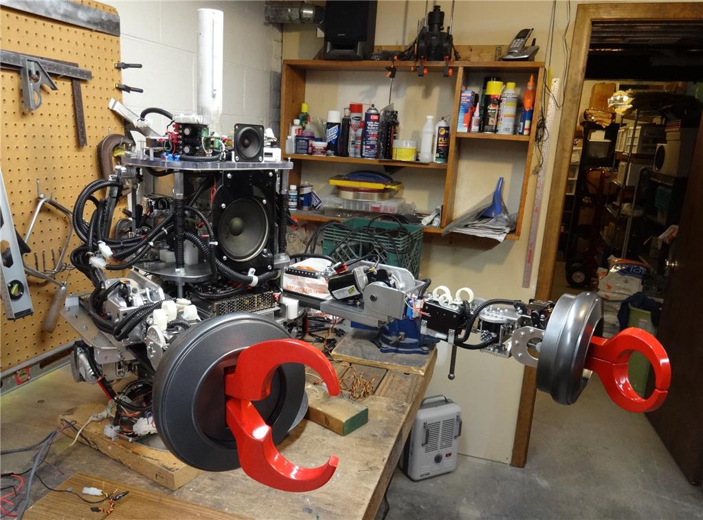
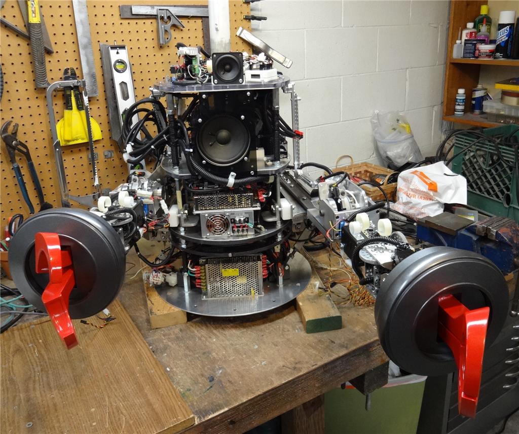
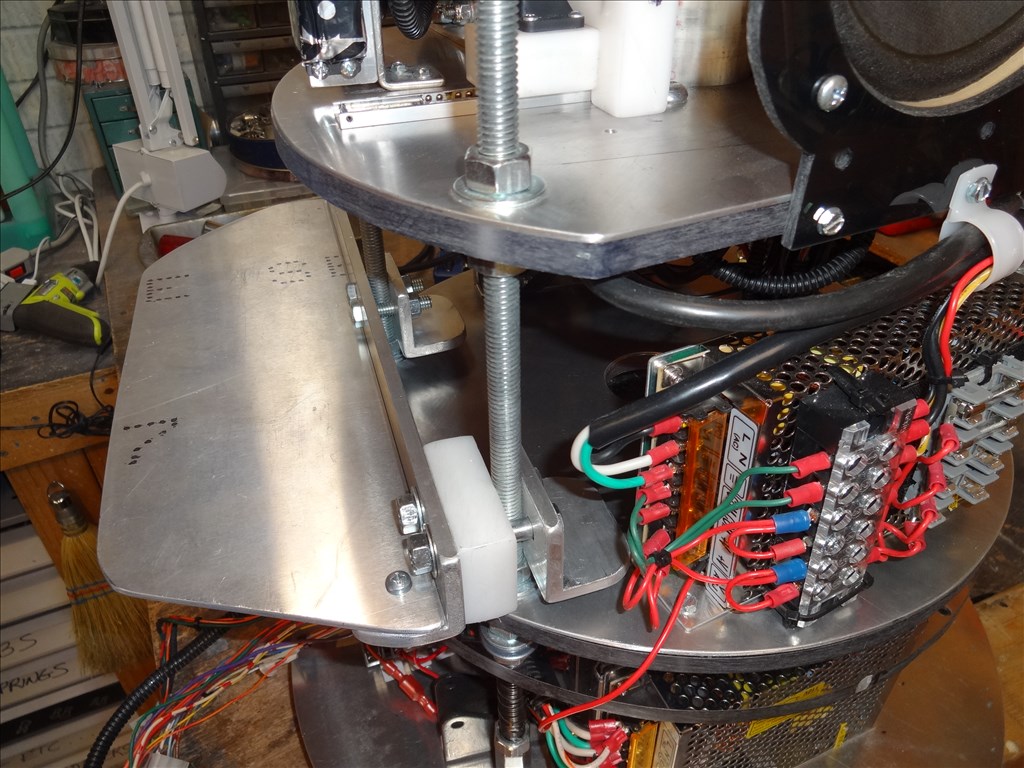
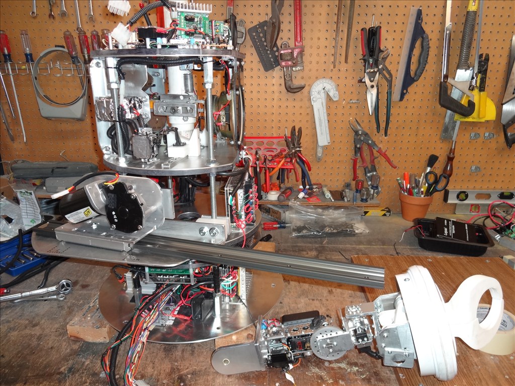
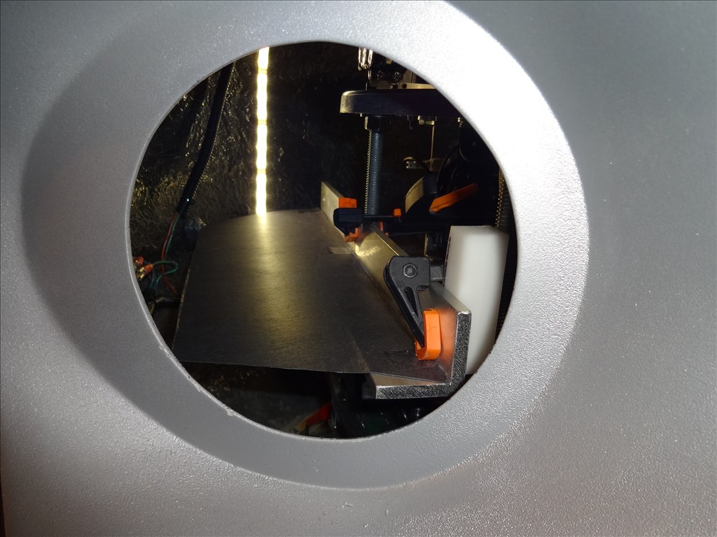
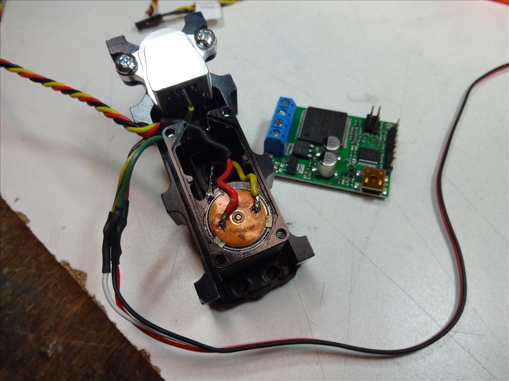
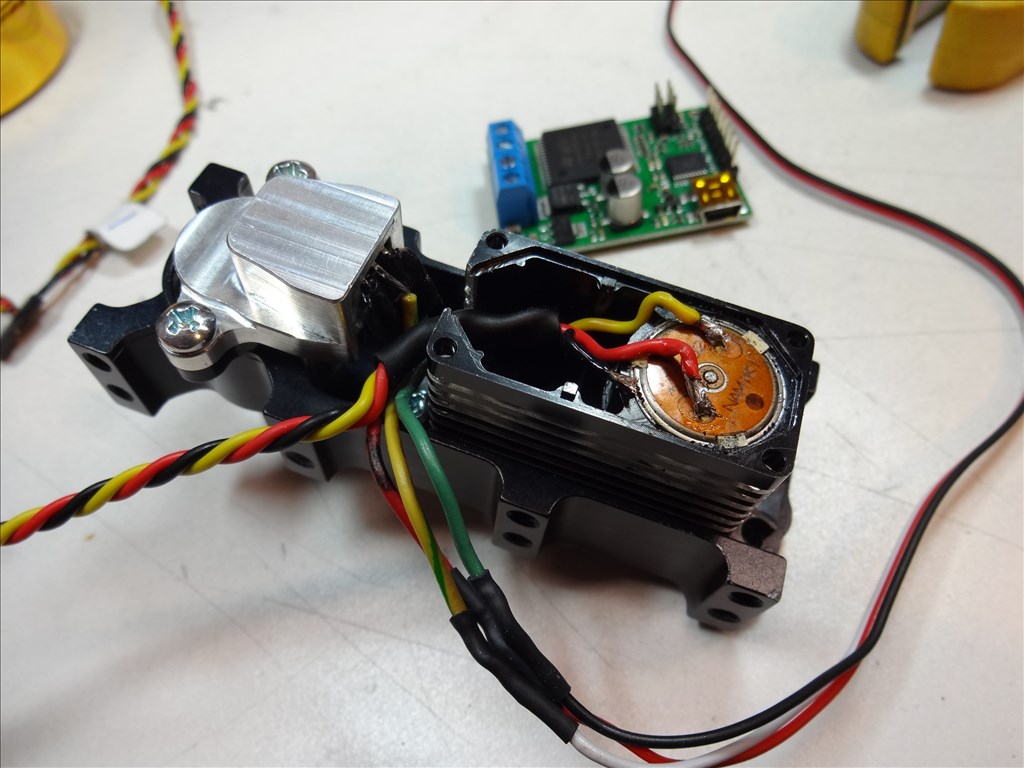
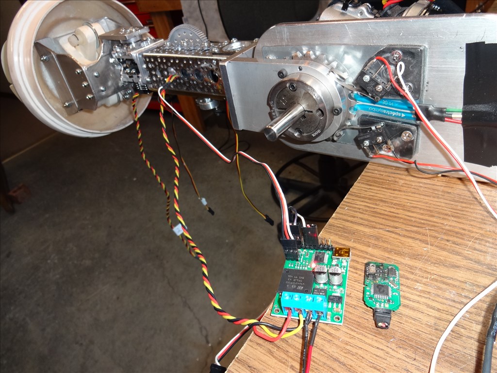
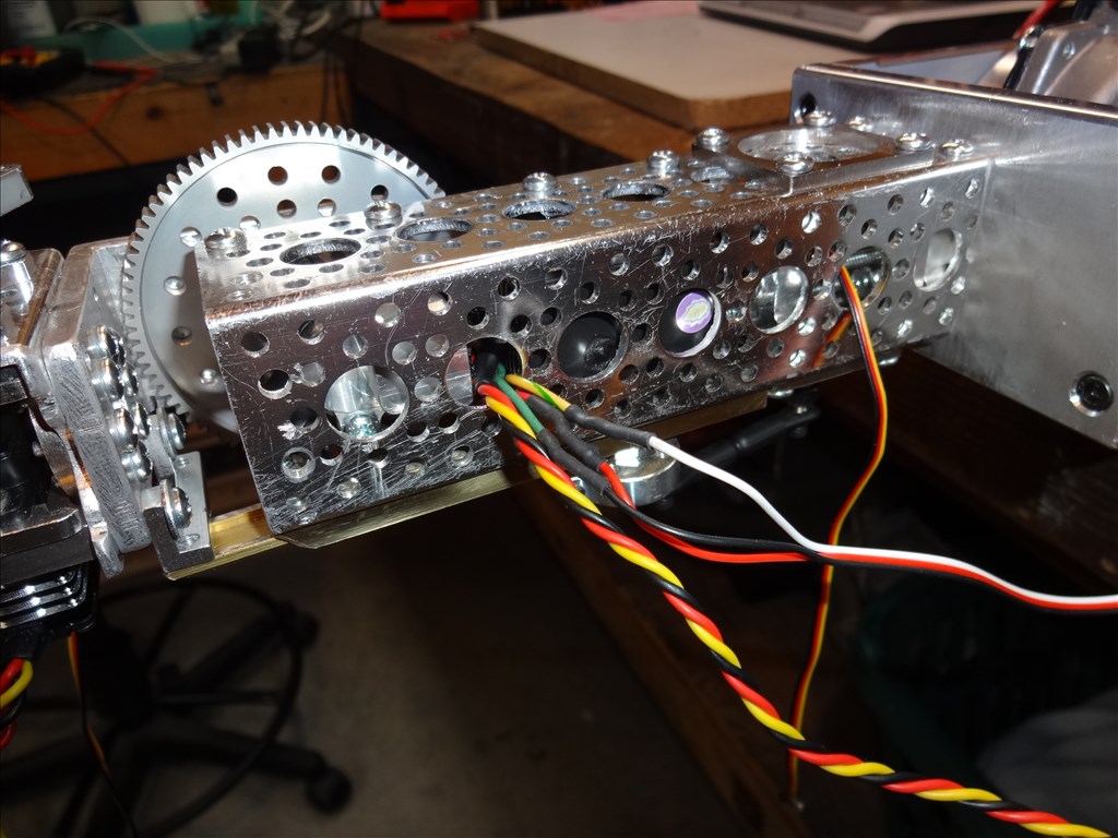
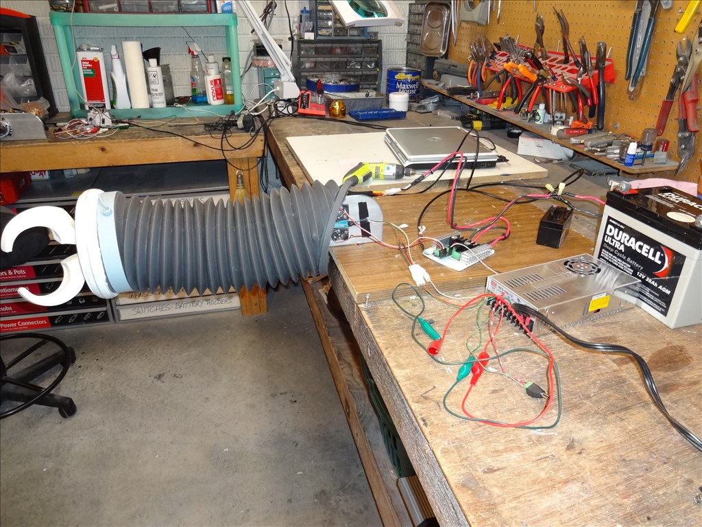
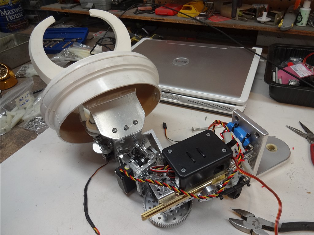
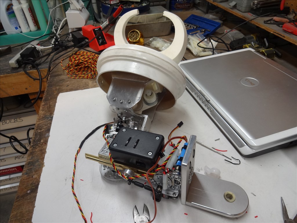
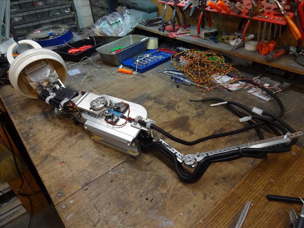
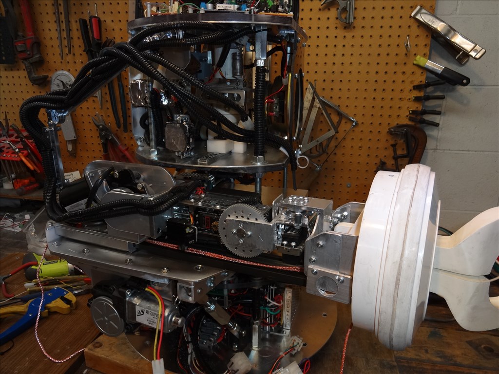
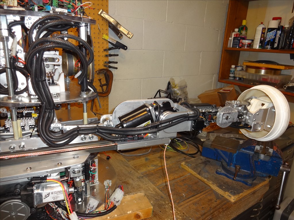
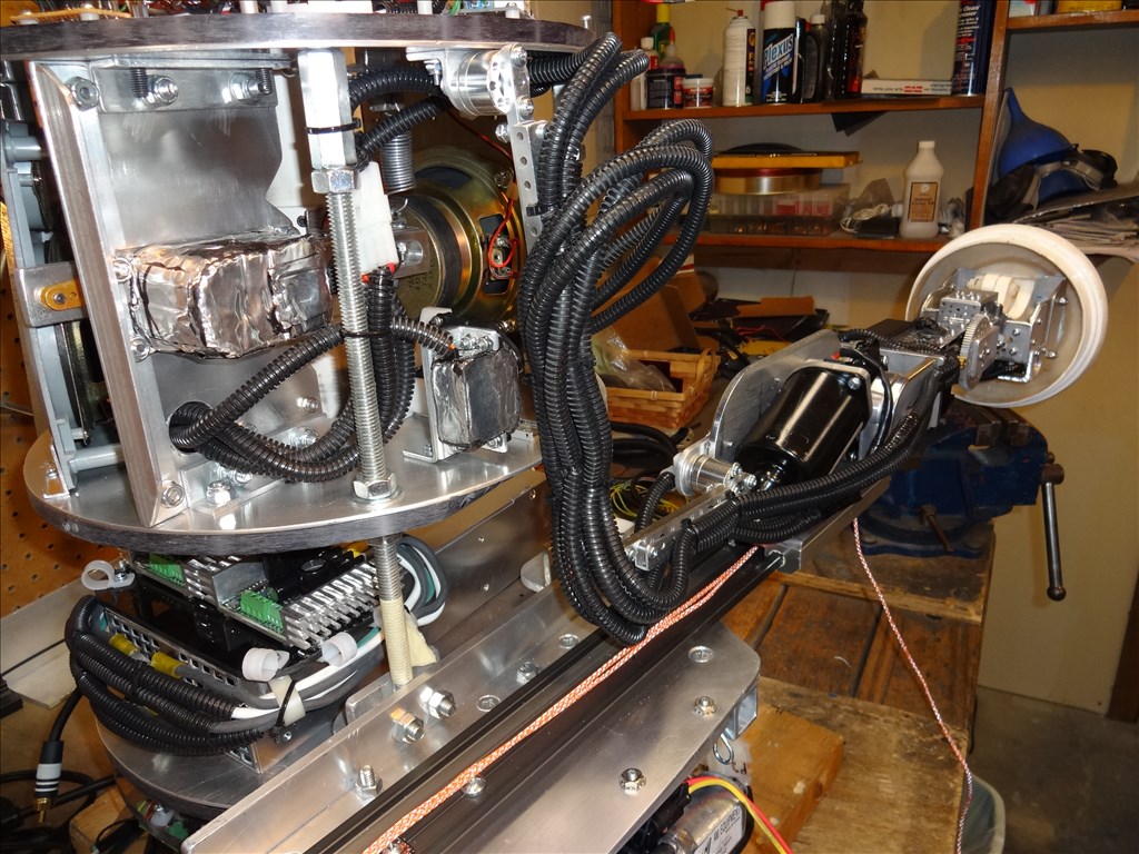
Well, I've had a setback. The motor that I had wanted to use in my arms don't appear to be strong enough to lift the load I need them to lift. I mounted one and loaded it with only about 1/3rd of the weight I will want it to lift and it's a no go.
I guess I need to search more for a motor strong enough and small enough to do what I want.
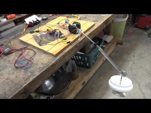
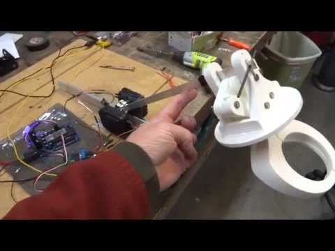
I'm a little discouraged. I had hoped these little guys would do the job. Here's a vid of what it looks like. If anyone has any ideas, I'm all ears.
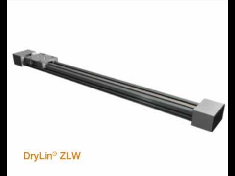
@Dave ...sorry to hear that! So now its time for dc motors with a shaft at both ends for position feedback and using another 2 ADC ports , with yet another H -bridge
 or try supporting the arm with a couple or three bungees doubled a couple of times for a small space to "assist" with the load......if your not getting that idea I could send a drawing (pics are worth a thousand words )
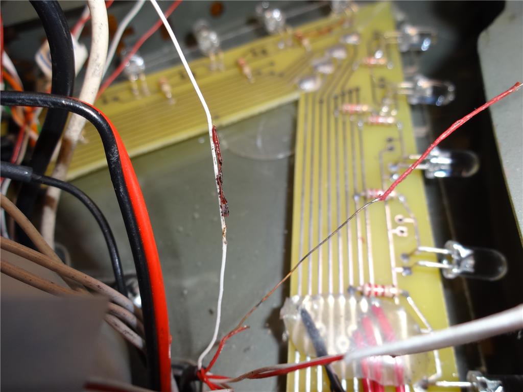
My robosapian project has such a mechanism using a spring to assist in lifting. I had it apart today in fact replacing about 30 wires that had insulation falling off! One of the forum members warned me of the common issue with the robo's...I really think it might wok for you even using the servo that you have!
Glen
or try supporting the arm with a couple or three bungees doubled a couple of times for a small space to "assist" with the load......if your not getting that idea I could send a drawing (pics are worth a thousand words )
My robosapian project has such a mechanism using a spring to assist in lifting. I had it apart today in fact replacing about 30 wires that had insulation falling off! One of the forum members warned me of the common issue with the robo's...I really think it might wok for you even using the servo that you have!
Glen
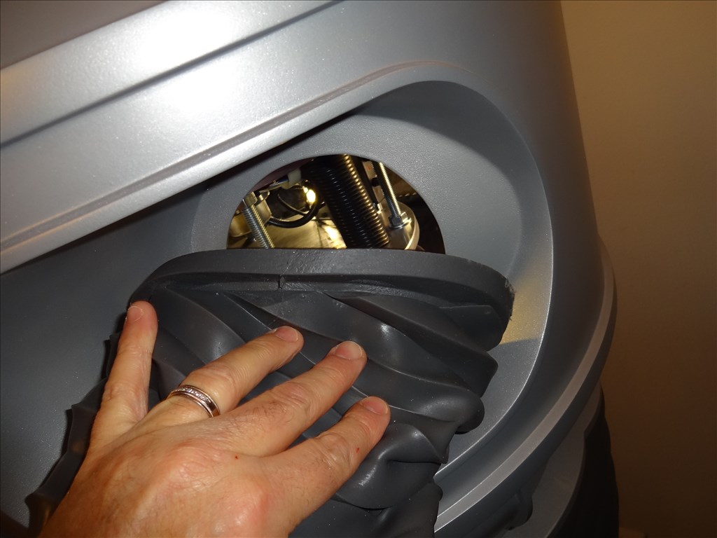
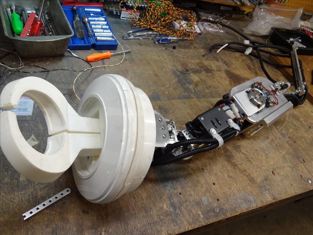
Thanks for the suggestion Glen. However I don't think I have the room inside the arm for a spring assist. Also the joints I have in mind are going to be a pan and tilt type. Not sure how a spring will work with that setup.
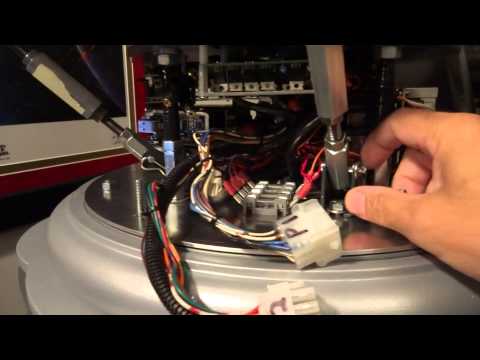
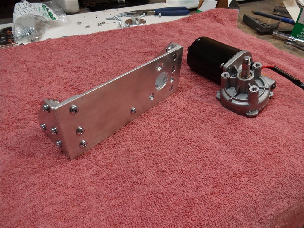
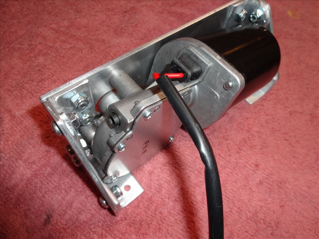
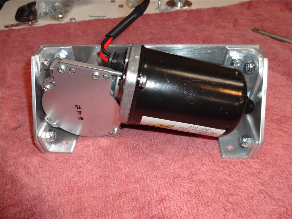
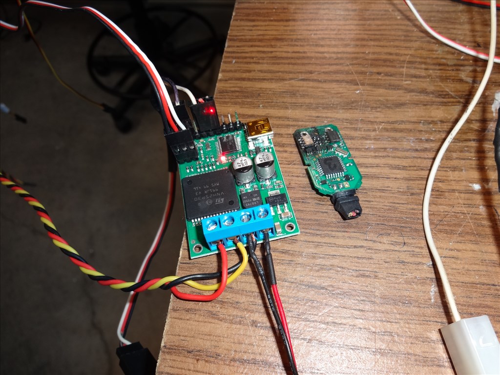
How many volts going to the motor? Can it lift it with power hooked straight to the motor?
@McDaver , in this vid I had 12vcd going to the motor but have had it running at a nice speed at 24vdc. I know it's hard to trace but I do have the motor running directly from the power supply.
Arrrgh! Dave, so there is no room on the inside of the torso directly opposite the arm? ...where a spring assist might go? I am guessing its tight with frames and electronics?! If that's the case you might have to redesign for only one motion, or move stuff around inside the torso to accommodate a spring assist..................arrrgh I feelin for ya