


-635353562186322812.png)


Hi all,
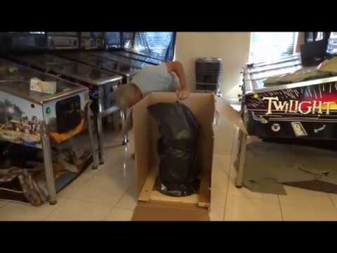
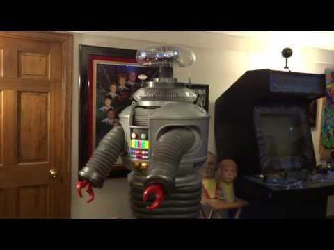
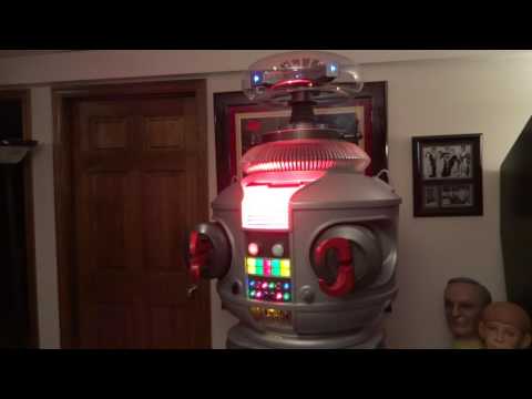
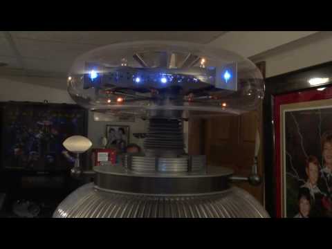
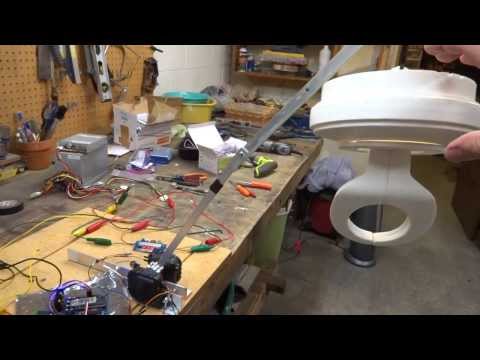
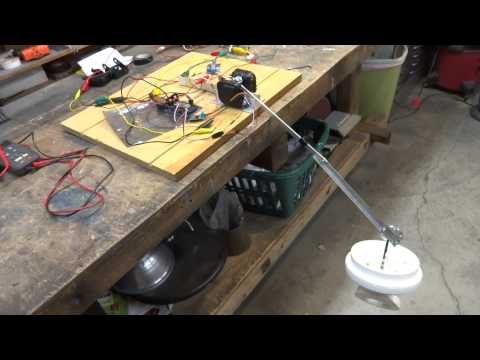
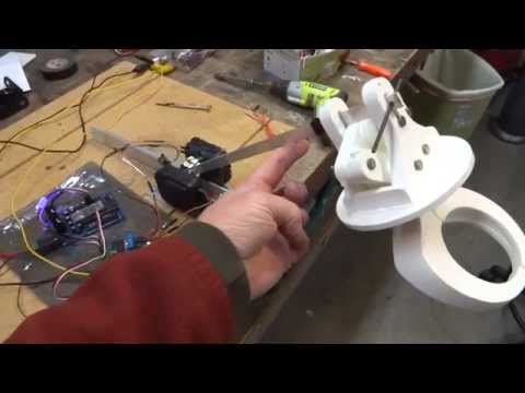
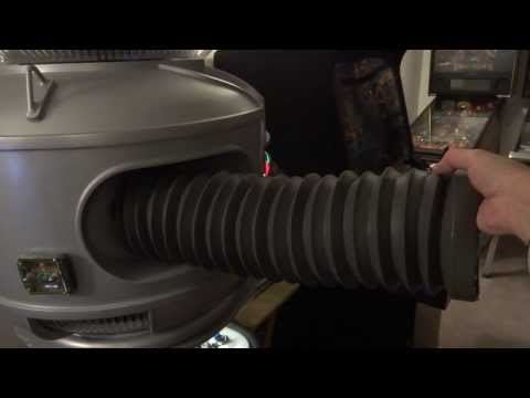
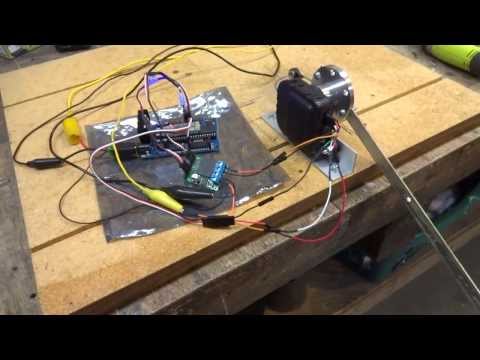
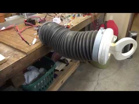
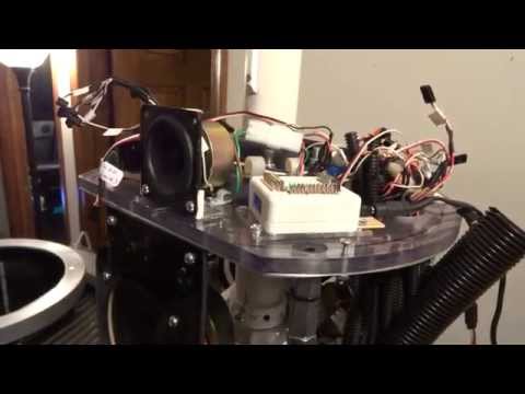
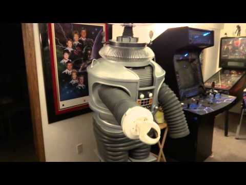
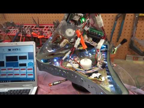
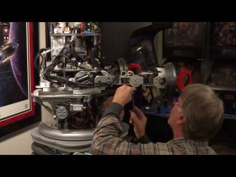
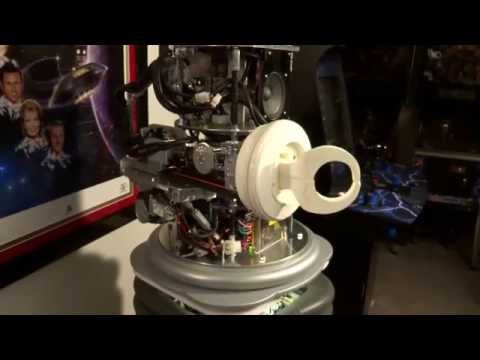
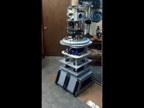
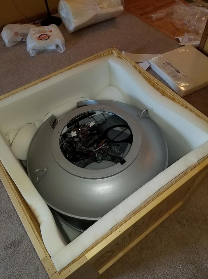
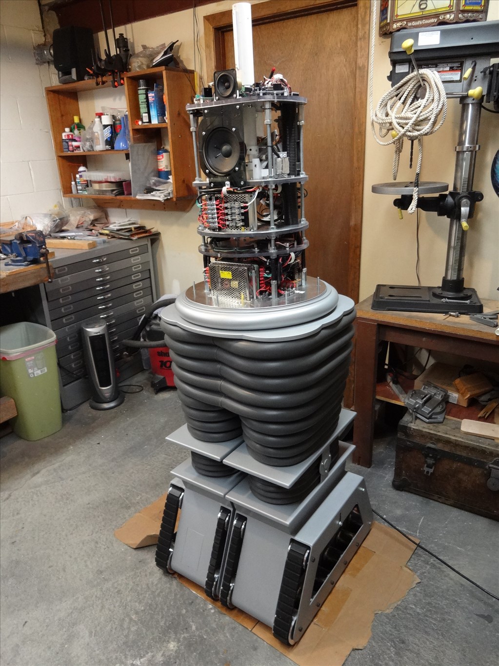
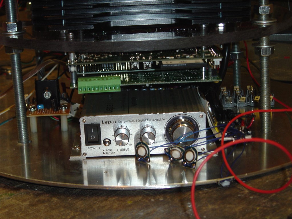
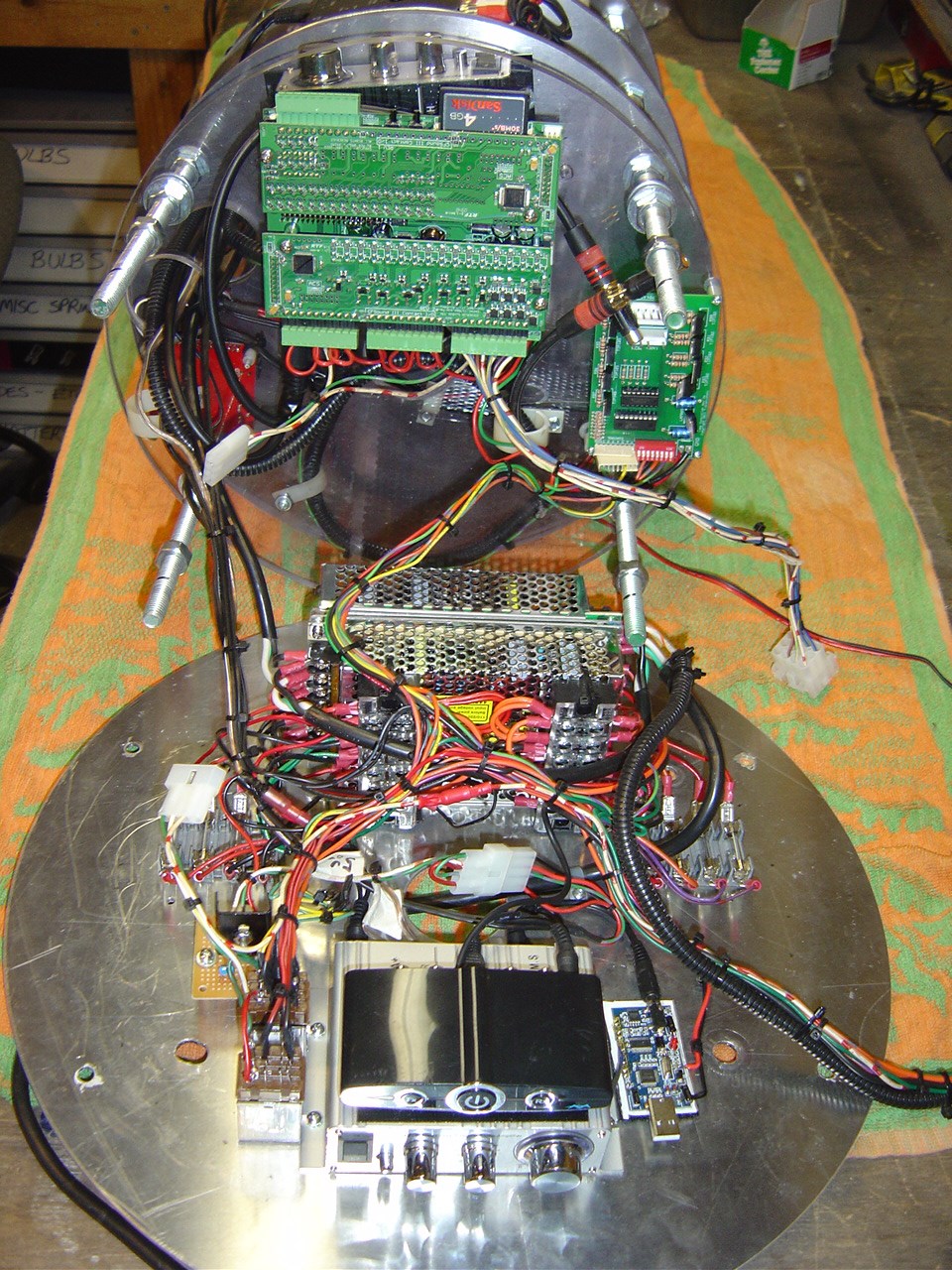
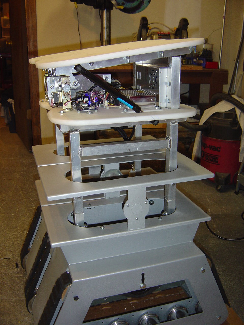
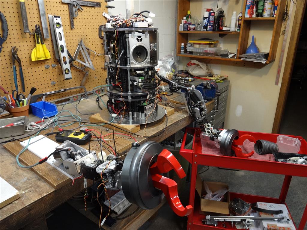
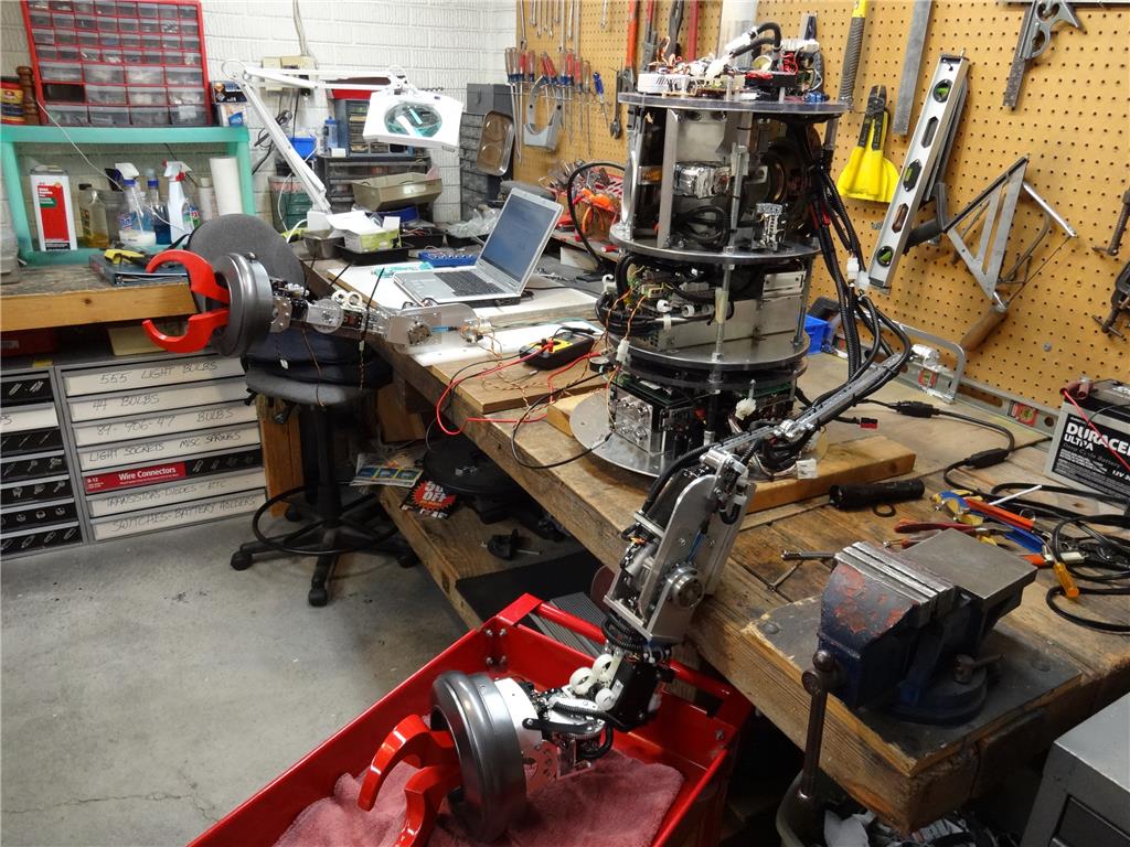
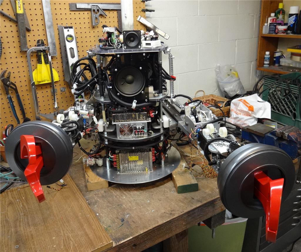
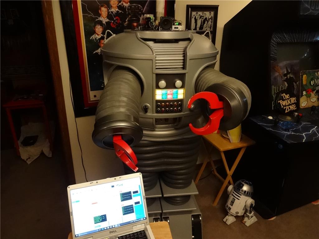
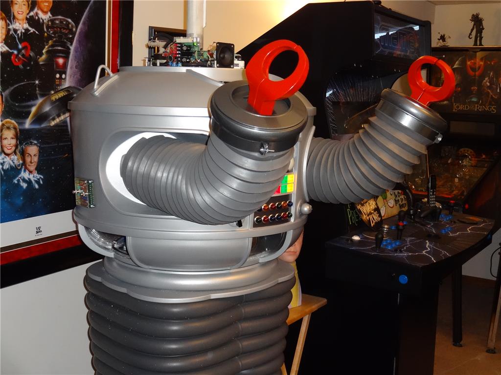
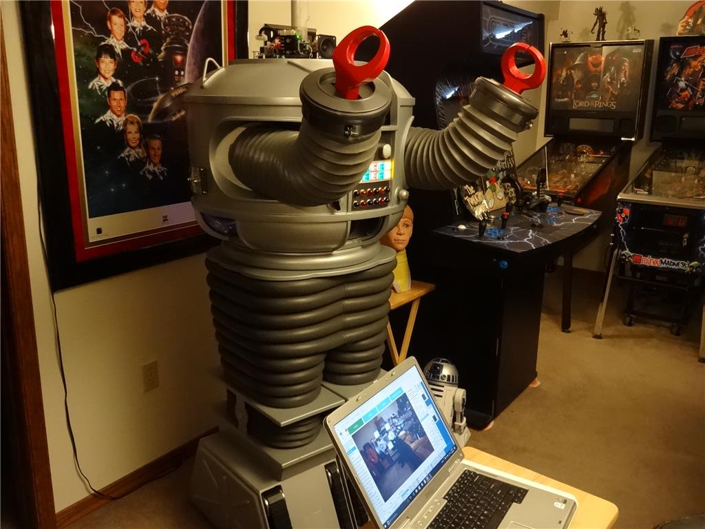
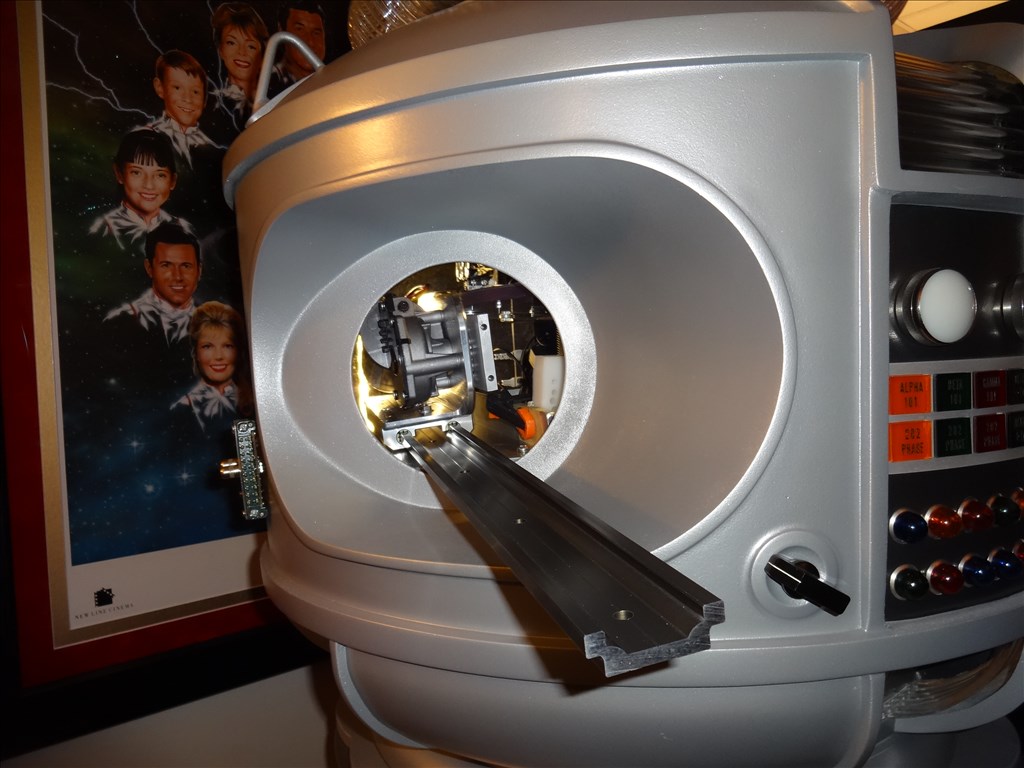
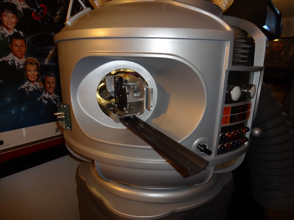
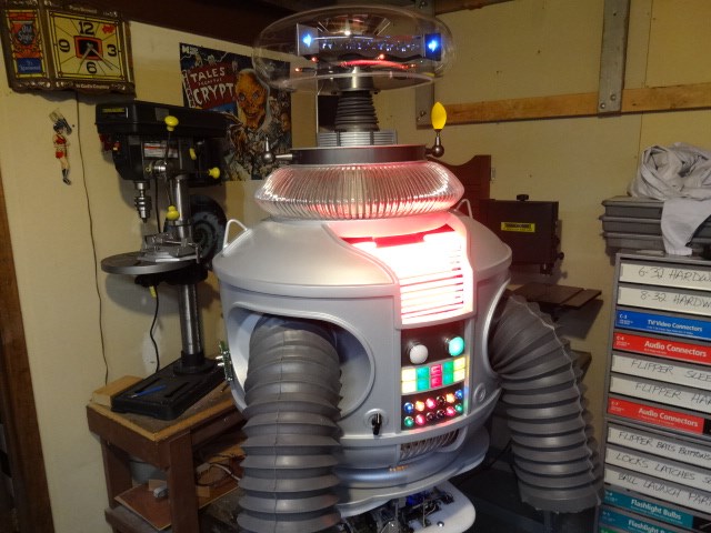
I'd like to share a video I just took of my full size Lost in Space B9 robot that's controlled by two EZ-B controller boards. Right now they are controlling limited movement and voice response of a few motors, lights and sound files played from a Sparkfun MP3 Trigger board. Although I'm just starting with the animation and have more building on the actual robot the result (mostly thanks to the EZ Robot controller board) is shocking. Please have a look at this (4 minute) You Tube vid and enjoy.
Please excuse some Technical camera lighting and sound issues. This is the first time I'd made and posted a vid online.
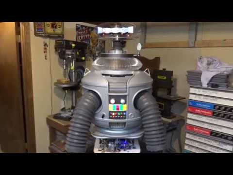
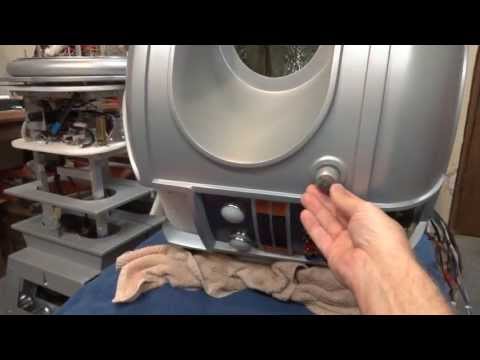
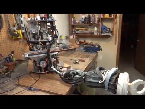
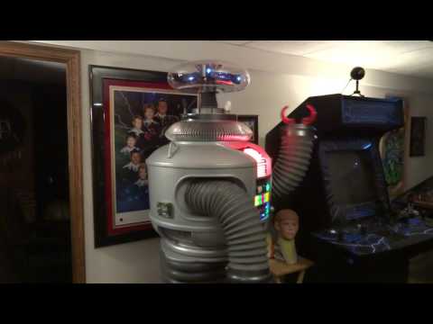
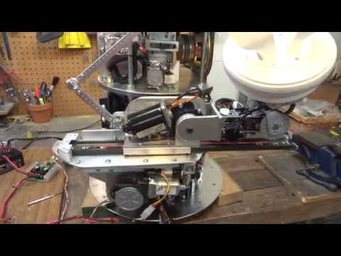
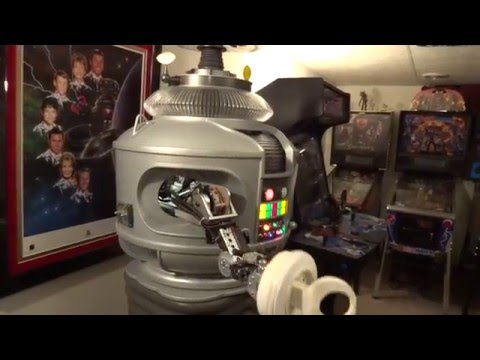
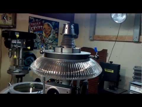
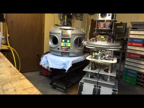
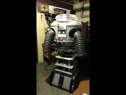
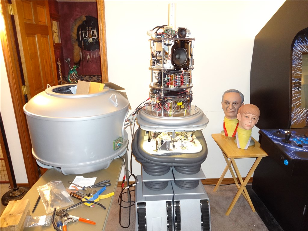
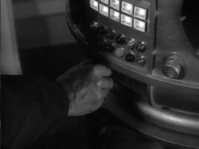
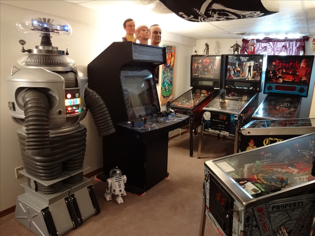
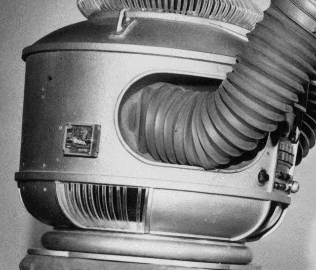
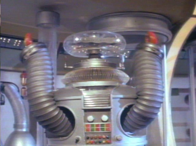
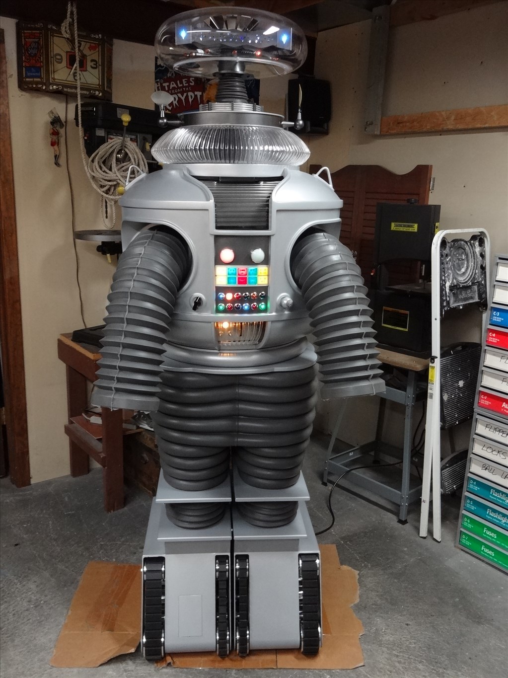
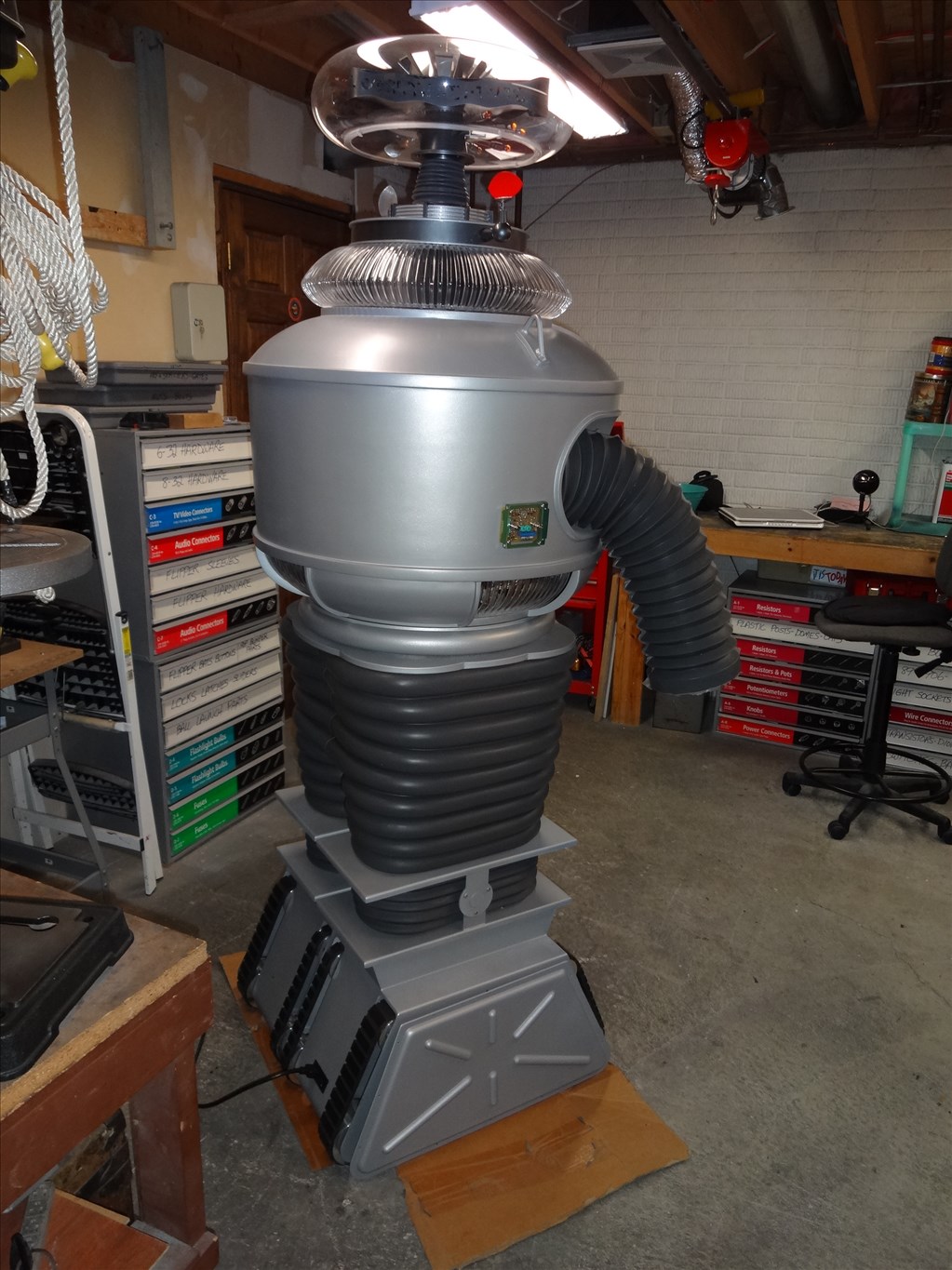
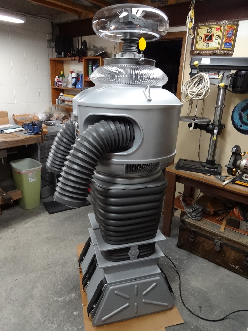
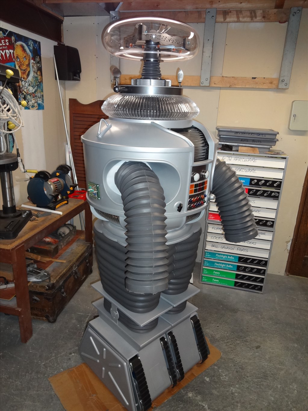
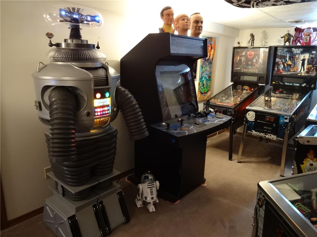
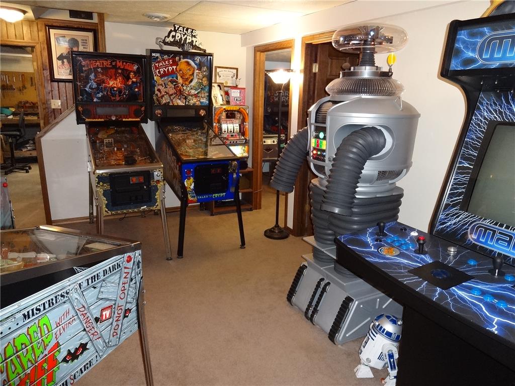
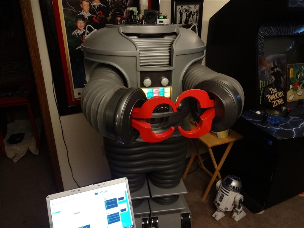
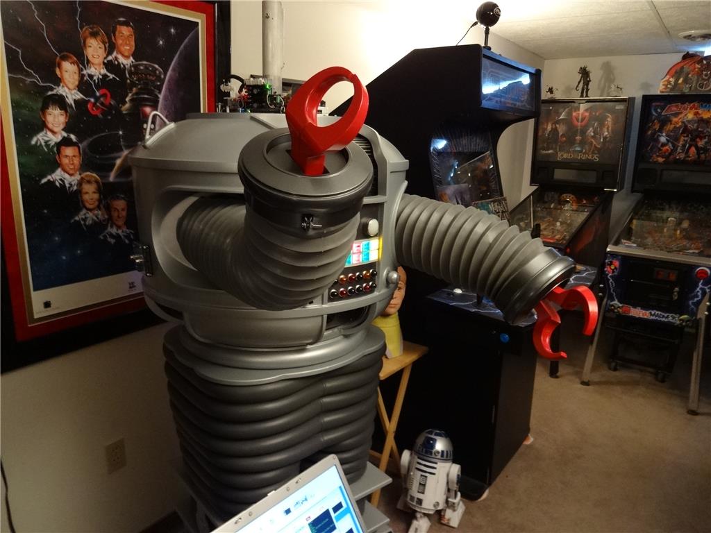
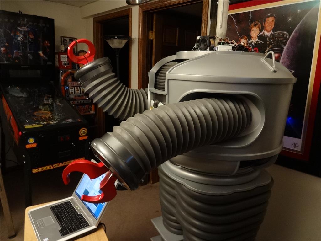
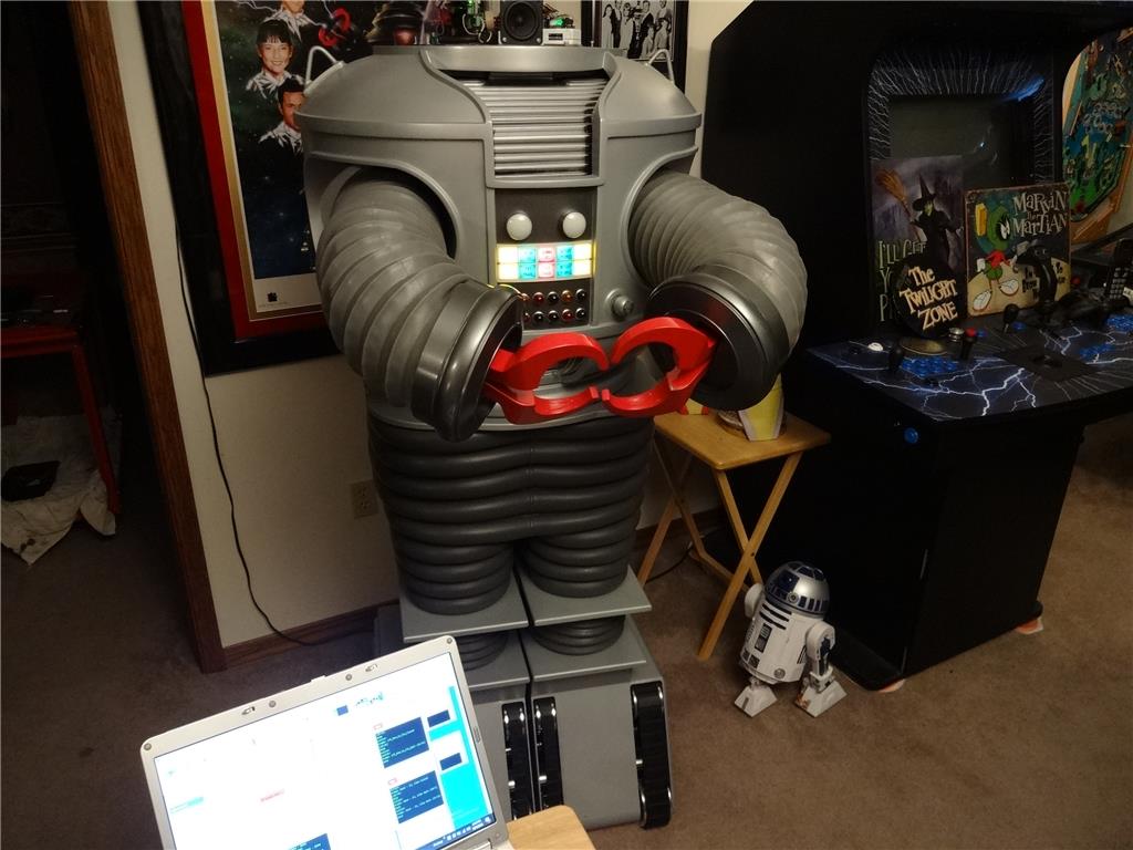
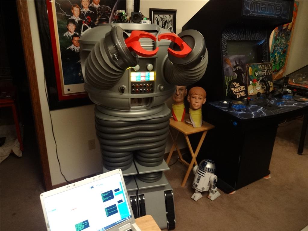
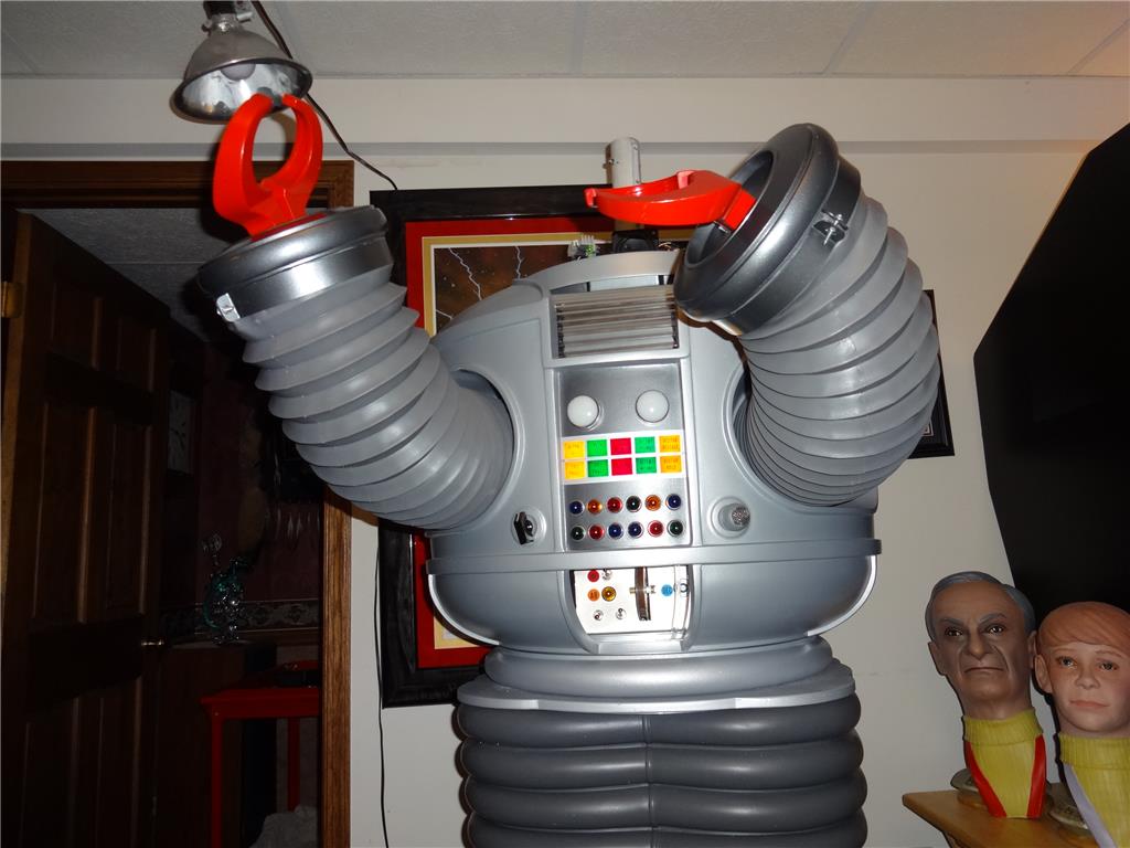
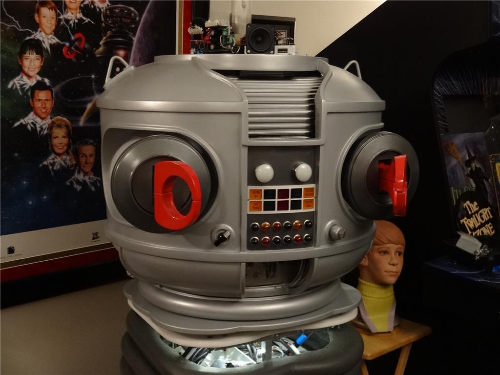
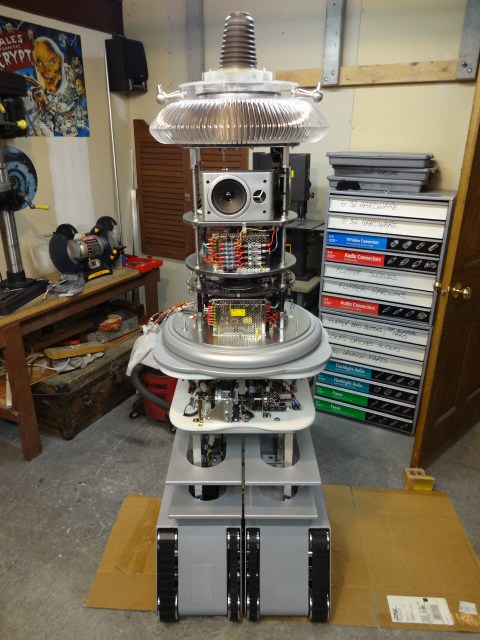
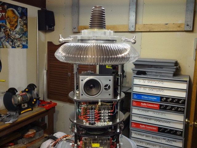
EDIT 8/2/13: Just realized I have no good pictures of how my B9 will look when complete. Here's one of the actual TV robots from the 60's TZ show Lost in Space and one recent shot of where I'm at with my build over 1 1/2 year after I started. Enjoy:


Thanks, Dave Schulpius
Discover more robots
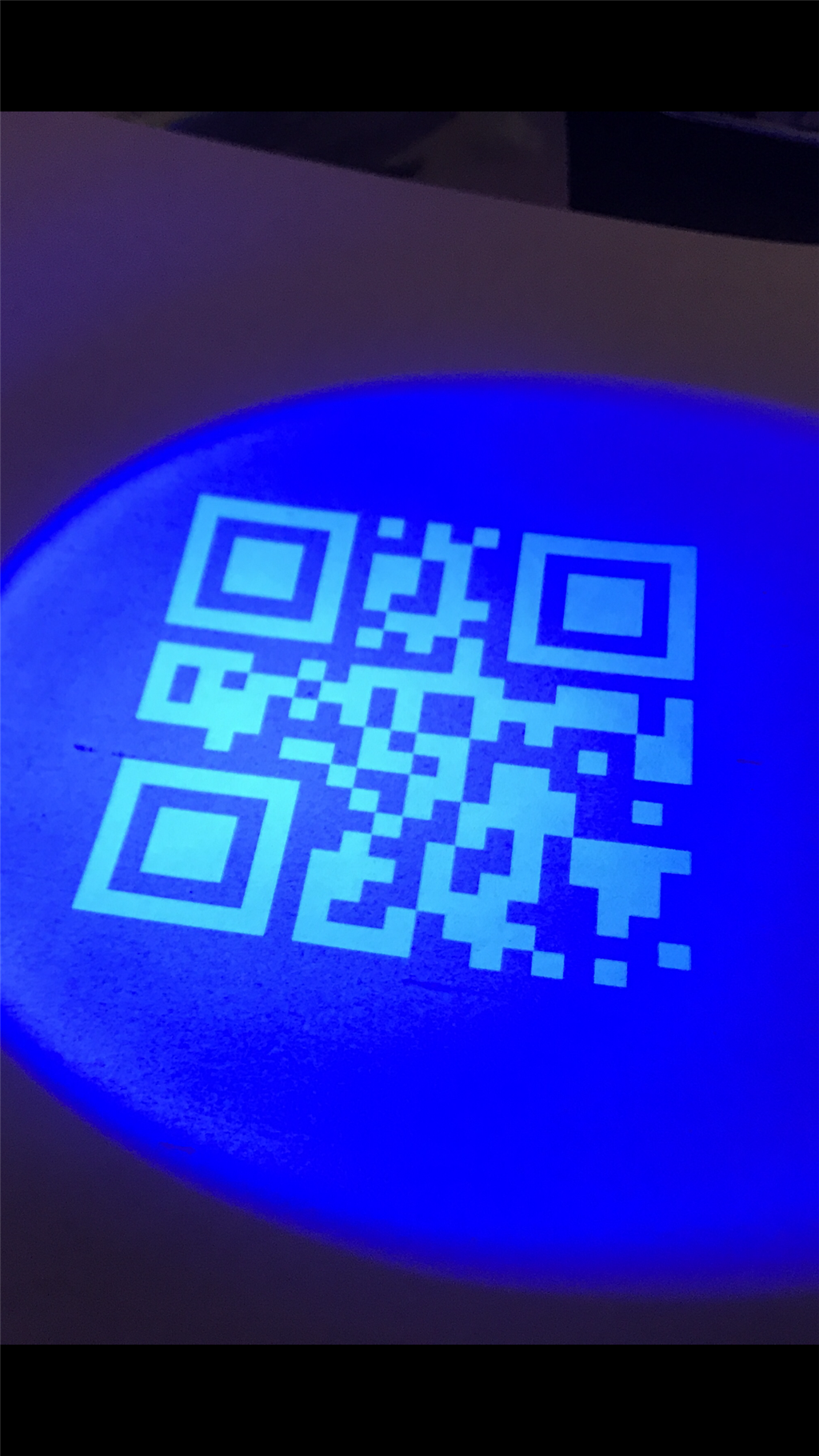
Jstarne1's Invisible Qr Code Project For Hackaday...
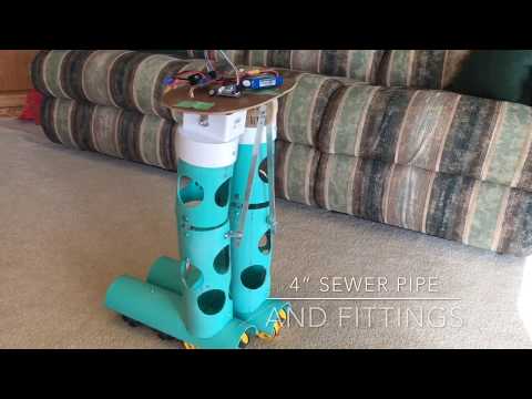
Steve's 2 Ft Biped Walking(Shuffle) Robot

He is awesome! And the EZ-Bs seem to work very well. I can't wait to see more progress!
Thanks Bret. Yes, the two EZ-B's are working great! DJ has made a few upgrades in the past few months that removed most to the little problems I was having. I'm sure after I fine tune everything I'll have it working close to perfect. One little annoyance you can see in the vid is he misinterprets common talk as commands sometimes. You saw him bend over on his own without me asking him to. I'm sure he heard something that sounded like me asking him to do it.
Loving it dave! This robot blows my mind. I'm so impressed with the work you put into it. I hope you get a lot of attention from this
Dave excellent job! I know he is not where you want him to be yet but looking from here you have done more than most ever will on a b9 project. I also like that he is scaled down a bit so he can move around the house without making a new doorway. Will he be semi autonomous? Just to let you know we love to see pics and videos of progress. Again great job! - Josh s
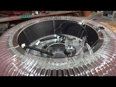
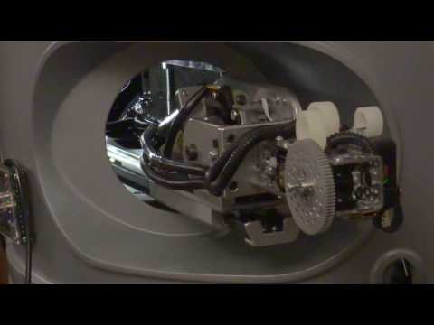
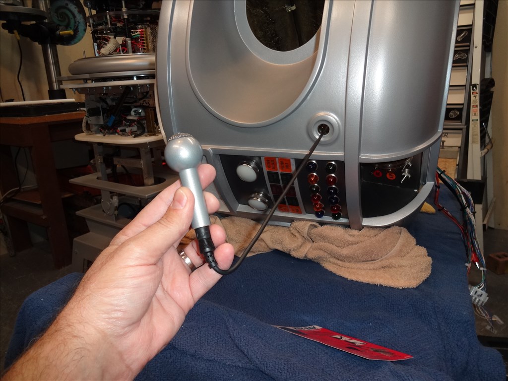
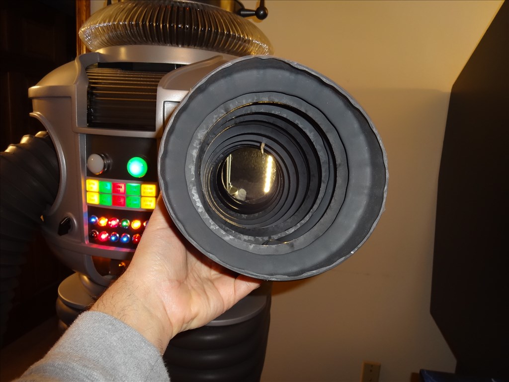
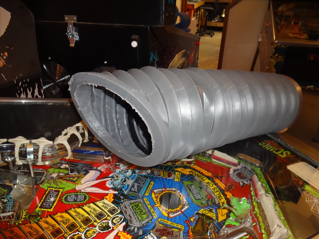
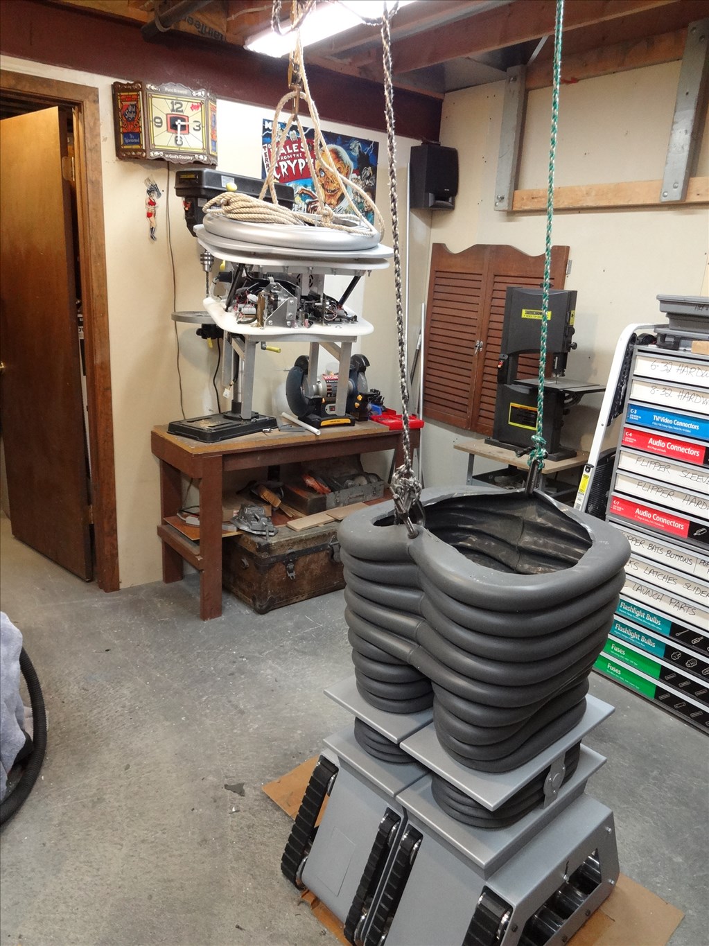
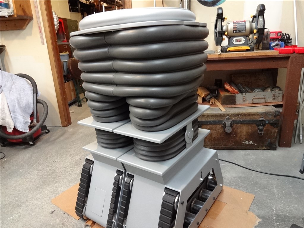
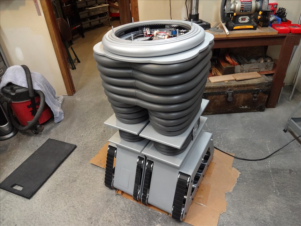
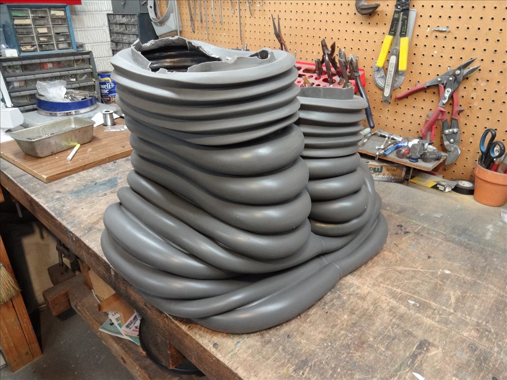
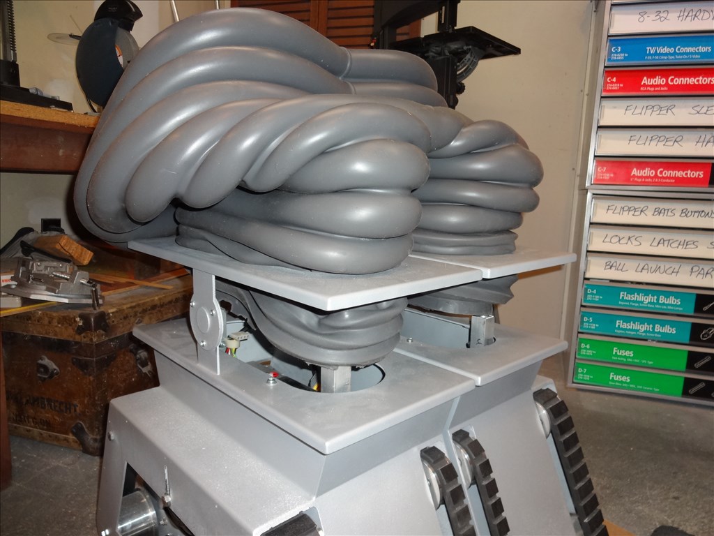
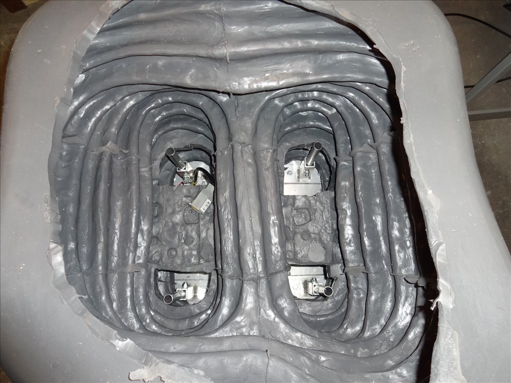
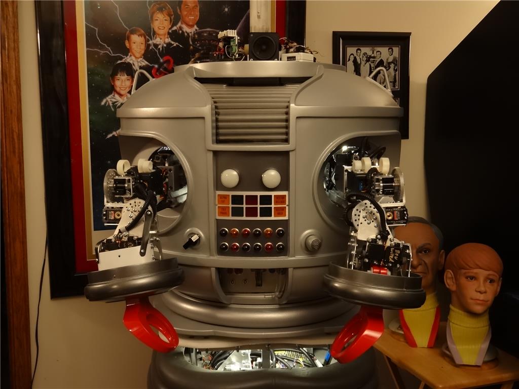
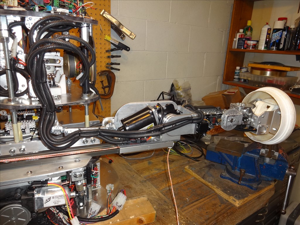
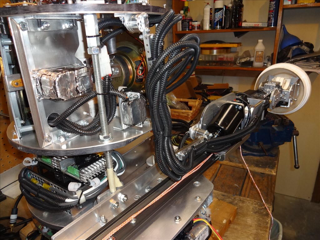
Thanks everybody. I've really enjoyed his project. A lot of the stuff I've never done before. When I first started I had no idea how I would control him or make him act real. Thanks to the EZ-B Board He is looking and actoing like the real TV robot more and more everyday. To answer Josh's is question; No he will not be Mobile. No real room in my home for all that. I don't want him scampering around the house. I can always add that later if I want. Right now I want to just complete him so he can stand there and look really cool. Also he is built to exact scale of the original TV robot. The mold that the fiberglass torso was poured into and the rubber arms and legs were pulled from the original TV robot. very, very cool stuff. all other measurements including his height were taken right from the original also. I'm shooting for as close to exact as possible. He is very much man size as the original robot was just a costume with a person inside of it. Again thanks for the comments that all the help, Dave Schulpius
Looks awesome Dave.
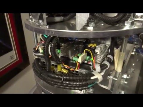
Just curious why (2) EZ-B boards?
Did you use up all the ports?
Or is it the upper/lower thing?
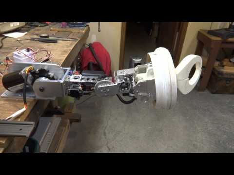
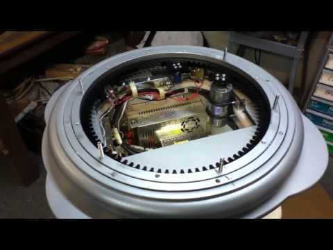
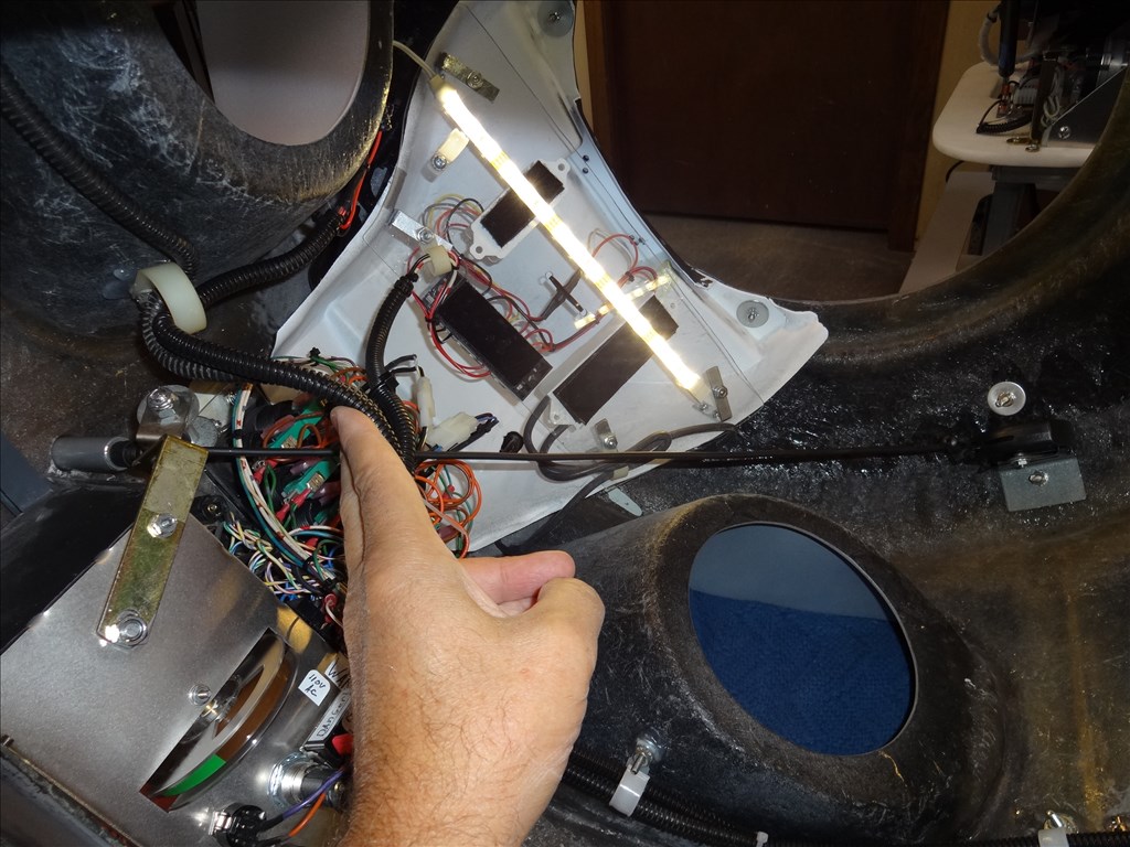
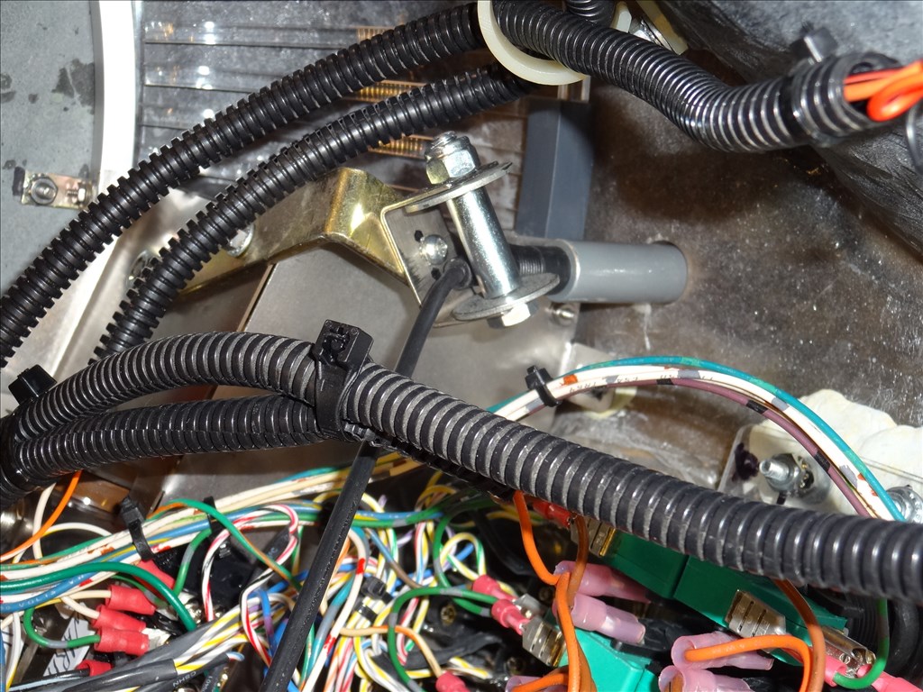
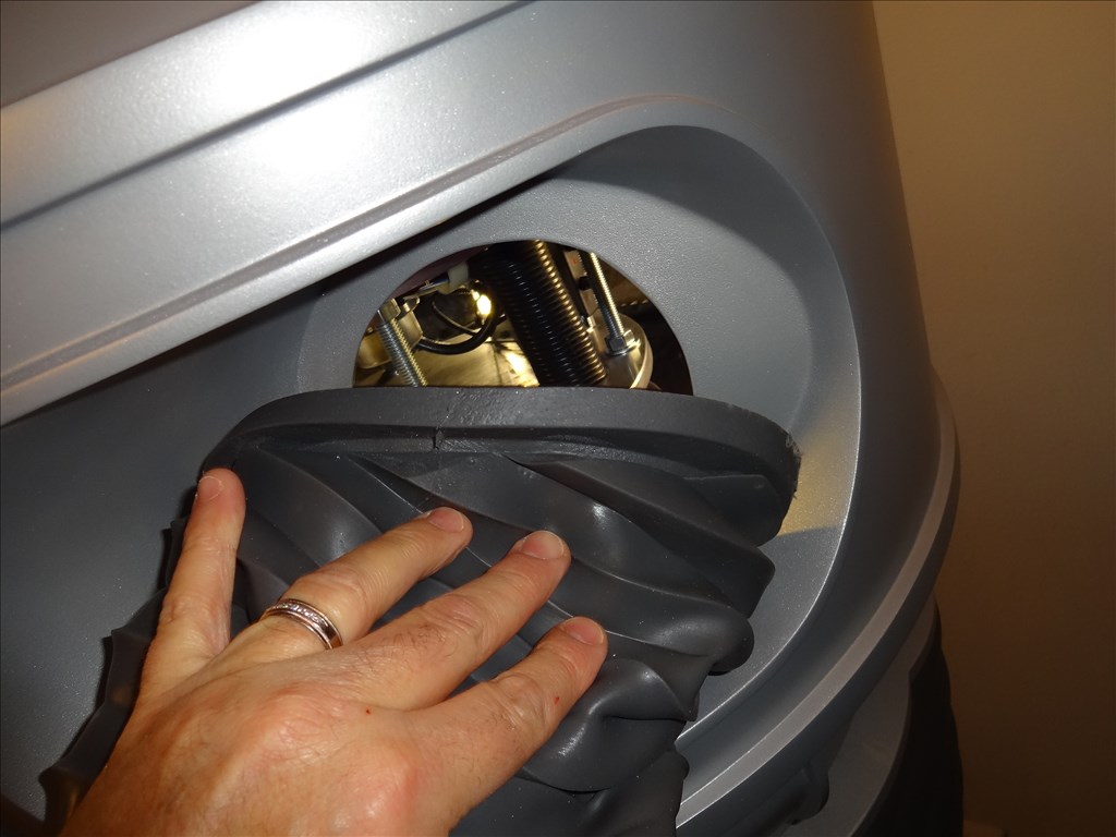
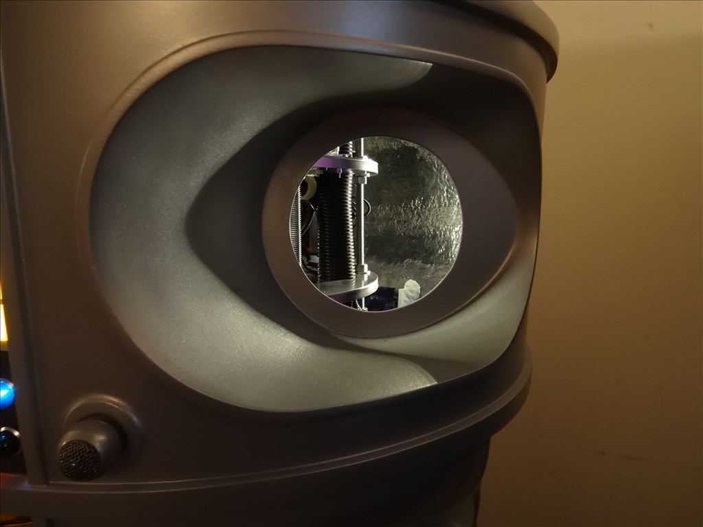
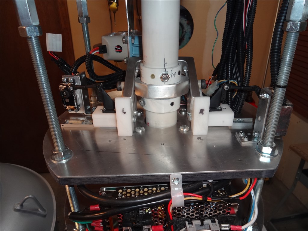
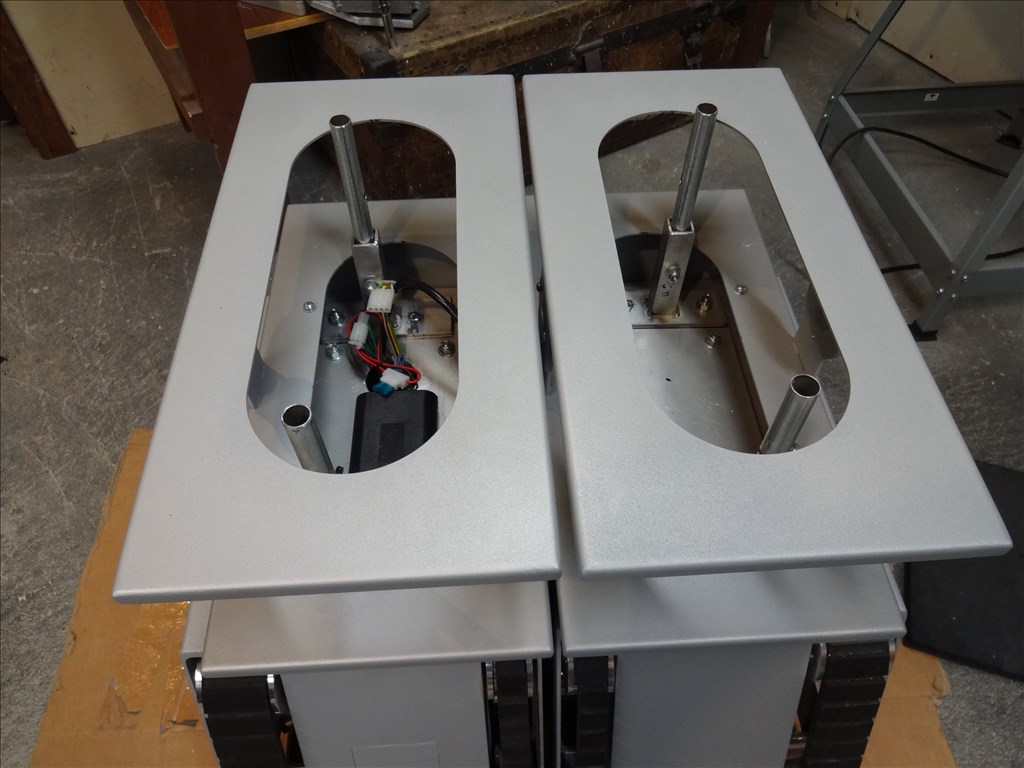
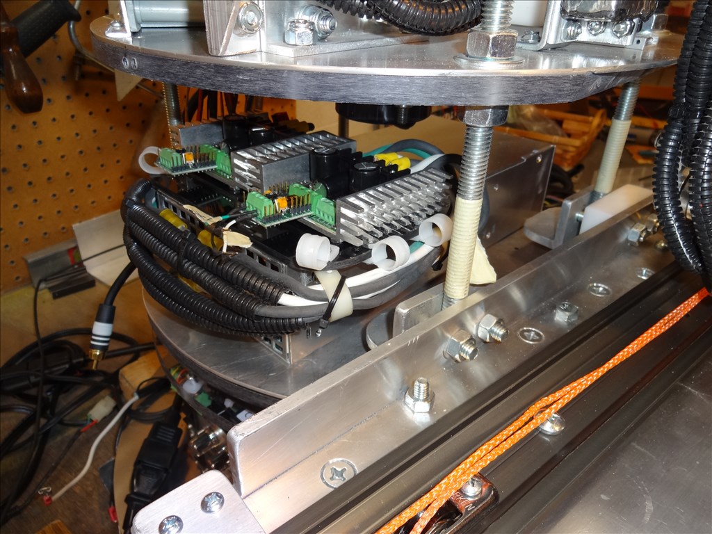
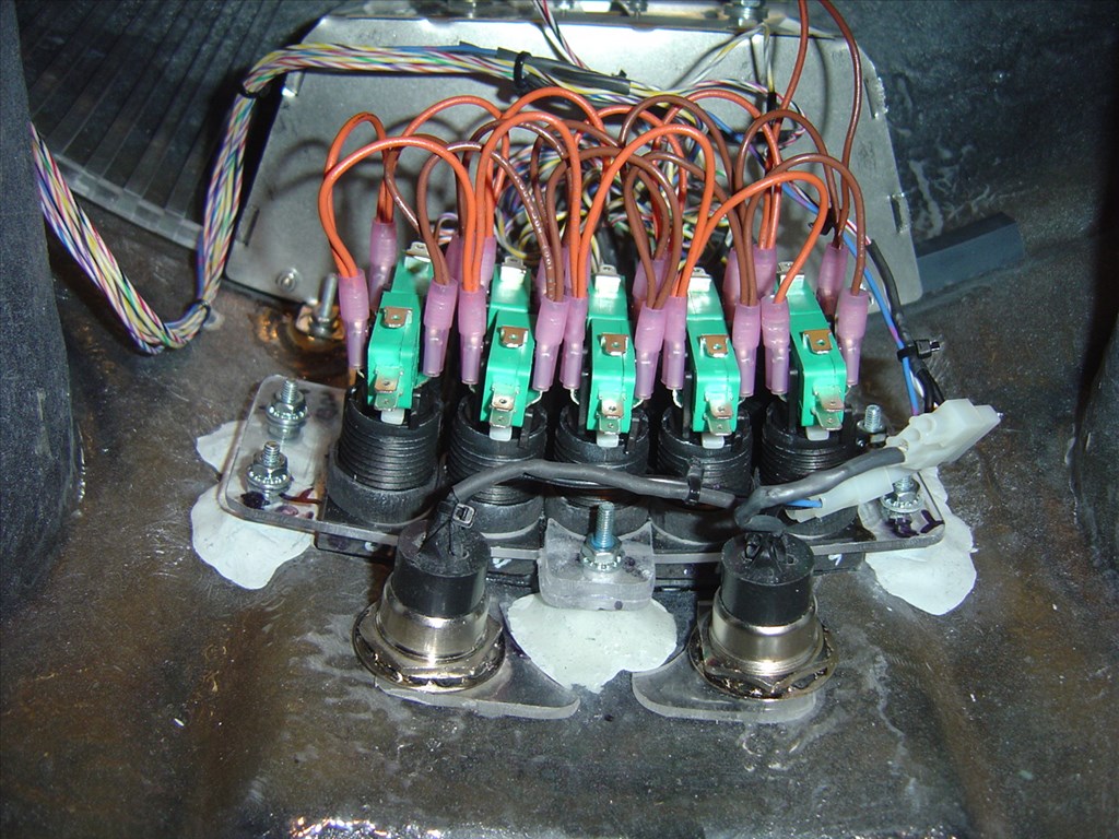
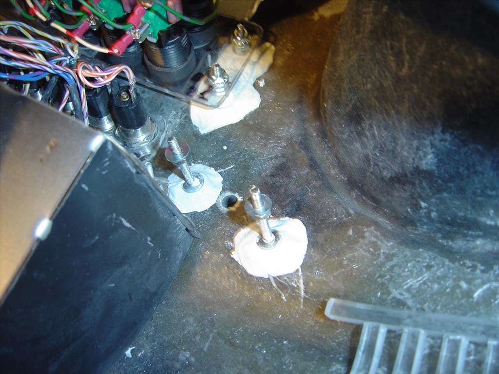
Thanks Lumpy! Yes, your right. It's a upper and lower thing. I just didn't want to run cables 3 to 4 feet from the top through the rotating and bending hips. The only cable I'll have running through there is a flexible extension 16 gauge power cord.
Thanks again, Davis Schulpius
That is coming out awesome Dave. I look forward to seeing more progress. Hopefully mine will be at that point eventually. You are motivating me to get some more work done on it.
I have a suggestion to eliminate him getting confused by overhearing talk not intended for him. I have been looking at Bluetooth headsets made for CB radios. They have a "push to talk" button. I will probably go that route with mine.
Keep up the good work. Maybe some day we can both bring our B9s to a convention. We can start an EZ-B division of the B9 Club.