


Asked
— Edited

Controller Options For Rover Upgrade
Hi @Athena,
I'm rebuilding my rover to improve mission capability and would appreciate advice on controller hardware.
Current setup (ARC project with an EZBv4 controller):
- Four stepper motors running at 12 VDC, ~1 A each. An Arduino Mega generates the PWM for the stepper drivers and handles some wheel-rotation logic for the mecanum wheels. The Arduino is separate from the EZBv4.
- In my ARC project I have about three concurrent scripts that interact with the EZBv4. Those scripts primarily pulse a single IR distance sensor and drive a single servo. The sensor and servo are connected through the EZBv4.
- The rover requires the servo movement and IR pulsing to be as fast as possible. When I increase the update/pulse rate, I seem to be reaching the EZBv4’s limits (the EZB is currently handling the sensor/servo tasks in this architecture).
- I will be changing the rover DC bus to 24 V.
Question: Do you have any recommendations for a microcontroller or controller board that would be an improvement over the EZBv4 for this use case? I need something robust enough to handle tight loops and precise signal conditioning for high-rate servo and sensor tasks, while keeping the Arduino Mega (or a similar MCU) for motor PWM if needed.
Thanks, Jack
Related Hardware (view all EZB hardware)
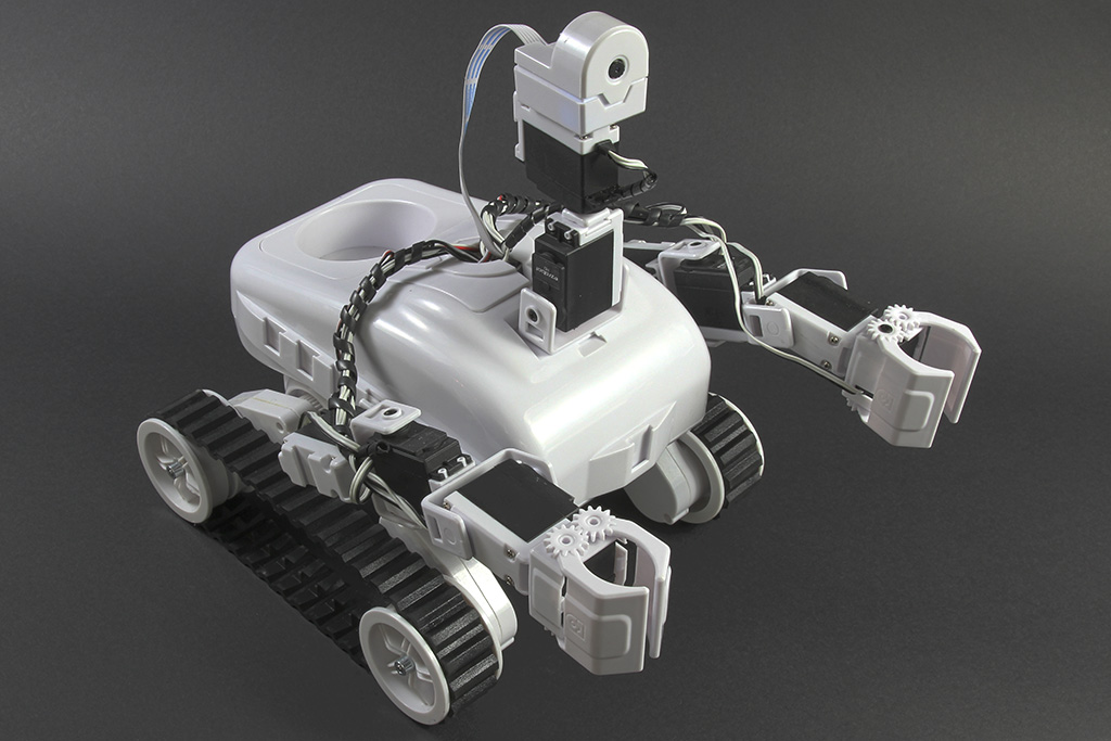
Roli Rover
by EZ-Robot
Roli WiFi planetary rover kit, customizable with 13 ez-bit ports for add-ons, built to traverse varied surfaces. Sold by EZ-Robot
Wi-Fi / USB
Servos
24
Camera
Audio
UART
3
I2C
ADC
8
Digital
24
Related Robot Skills (view all robot skills)

EZB Connection
by Synthiam
Connects EZ-B I/O controllers to ARC via COM or IP (5 connections). Supports init scripts, battery monitoring, TCP/EZ-Script server and serial/I2C.

Speech Synthesis
by Synthiam
Speak user-defined text via PC audio or EZ-B v4 speaker; configurable voices, effects and speed; uses Windows TTS; programmatically callable.

Yes - with those parts, I can make this much more concrete.
What your updated architecture looks like
That is a solid split for a rover that needs better real-time performance.
Cleaner ASCII wiring schematic
Power rails
24 V rail
Use this for:
Do not feed 24 V directly to:
5 V rail
Use this for:
A good rule here is to use a separate high-current 5-6 V regulator for the servo, not the MCU’s 5 V pin.
3.3 V rail
Use this for:
The Teensy 4.1 is a 3.3 V logic board. Its pins are not 5 V tolerant in general, so this matters a lot for serial.
Logic voltage levels
Arduino Mega
Teensy 4.1
EZBv4
UART / serial wiring
You said:
That can work, but here’s the key constraint:
Example serial wiring for Teensy-safe UART
Option A: EZBv4 TX to Teensy RX through a resistor divider
That drops a 5 V-ish signal down to around 3.3 V.
A common equivalent pair is:
If you want, I can also give you a more conservative divider like 10k / 20k, which is often easier on signal loading.
UART direction arrows
Suggested pin map example
This is just an example layout to make the diagram concrete.
Arduino Mega + CNC Shield v3.0
The CNC shield typically uses the Mega’s step/direction pins mapped for the four axes.
Typical signal grouping:
The exact shield pin mapping depends on the shield version, so confirm the shield silkscreen/manual. The DRV8825s then receive:
Teensy 4.1
Suggested use:
Example:
Sensor wiring: Sharp GP2Y0A02YK0F
Typical connections:
Important note
This sensor outputs an analog voltage, so it is not a UART device. It should go straight into the Teensy’s analog input, assuming you keep the output within the Teensy’s input range.
Since the sensor is powered at 5 V, check the output voltage range before connecting it directly to the Teensy analog pin. If needed, add a divider or conditioning network.
Servo wiring: DS RDS3225
For the servo:
Important
Do not power that servo from the Teensy or EZBv4 logic supply unless the regulator can handle the current. A 25 kg-class servo can pull large current spikes.
Grounds that must be tied together
This is critical.
All of these should share a common ground:
If you do not share ground, UART and PWM signals can behave unpredictably.
Cleaner wiring summary
Two practical cautions
1) servo power and noise
Put bulk capacitance near the servo supply if you can. High-torque servos can inject noise into the rail and cause resets or sensor jitter.
2) DRV8825 current setting
Make sure each DRV8825 current limit is properly adjusted for your stepper motors. That matters a lot once you move to 24 V.
ARC side note
If you want ARC to manage the communications cleanly, a custom robot skill can help you build a better interface between ARC and the Teensy/Arduino. That’s the right path if you want more than simple scripts:
https://synthiam.com/Support/Create-Robot-Skill/Overview
Final recommendation
Your current plan is workable, but I would slightly refine it like this:
If you want, I can make the next version into a pin-by-pin table like:
That would be the most useful next step for actual wiring.