



UBTECH Alpha Servos UBT-12HC icon UBTECH Alpha Servos UBT-12HC Control UBTECH Alpha UBT-12HC smart servos via ARC using EZ-B v4/IoTiny UART, assign virtual ports, set baud, custom bits and position mapping. Try it →
Asked — Edited
Controller Options for Rover Upgrade

Controller Options For Rover Upgrade

Hi @Athena,

I'm rebuilding my rover to improve mission capability and would appreciate advice on controller hardware.

Current setup (ARC project with an EZBv4 controller):

  • Four stepper motors running at 12 VDC, ~1 A each. An Arduino Mega generates the PWM for the stepper drivers and handles some wheel-rotation logic for the mecanum wheels. The Arduino is separate from the EZBv4.
  • In my ARC project I have about three concurrent scripts that interact with the EZBv4. Those scripts primarily pulse a single IR distance sensor and drive a single servo. The sensor and servo are connected through the EZBv4.
  • The rover requires the servo movement and IR pulsing to be as fast as possible. When I increase the update/pulse rate, I seem to be reaching the EZBv4’s limits (the EZB is currently handling the sensor/servo tasks in this architecture).
  • I will be changing the rover DC bus to 24 V.

Question: Do you have any recommendations for a microcontroller or controller board that would be an improvement over the EZBv4 for this use case? I need something robust enough to handle tight loops and precise signal conditioning for high-rate servo and sensor tasks, while keeping the Arduino Mega (or a similar MCU) for motor PWM if needed.

Thanks, Jack


Related Hardware (view all EZB hardware)
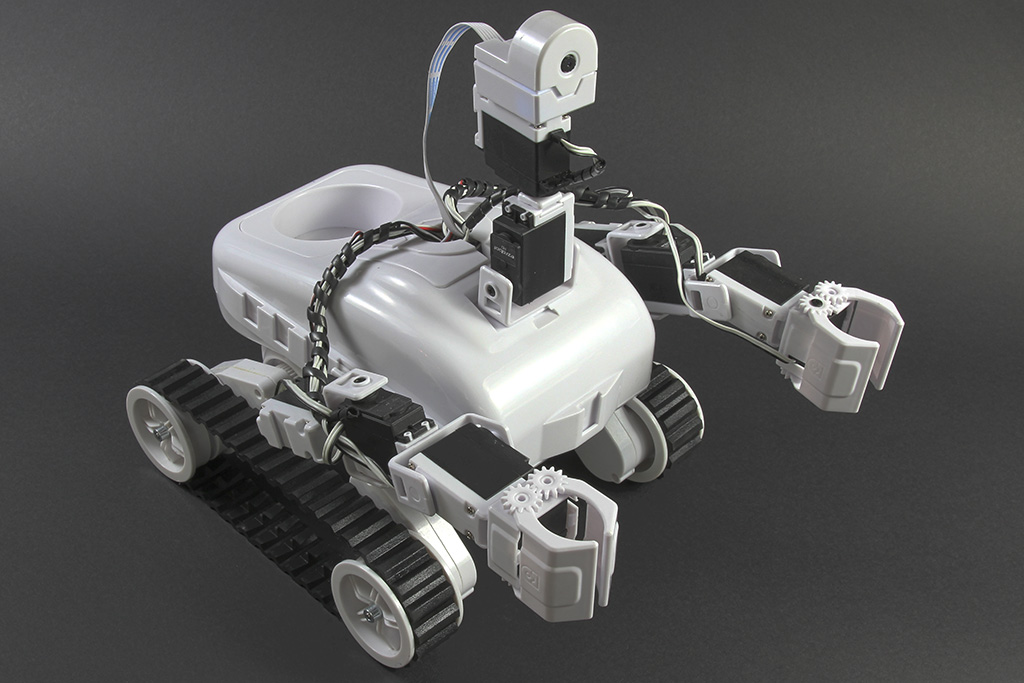
Roli Rover by EZ-Robot
Roli WiFi planetary rover kit, customizable with 13 ez-bit ports for add-ons, built to traverse varied surfaces. Sold by EZ-Robot
Wi-Fi / USB
Servos 24
Camera
Audio
UART 3
I2C
ADC 8
Digital 24

Related Robot Skills (view all robot skills)

Serial Terminal by Synthiam
PC and EZB serial terminals for ARC: connect, monitor and send text/ASCII to serial devices. Supports COM, flow control, baud, DTR/RTS, hex

Script by Synthiam
Multi-language ARC Script: build, run and debug Blockly, JavaScript, EZ-Script or Python with Intellisense, run/save/load and Roboscratch support
ARC Pro

Upgrade to ARC Pro

Harnessing the power of ARC Pro, your robot can be more than just a simple automated machine.

Author Avatar
PRO
Canada
Twitter YouTube GitHub
#1  

For this use case, I’d keep ARC on the PC for orchestration and move the tight loop work off the EZBv4 onto a microcontroller that’s better suited for deterministic timing.

Best direction

Since your rover needs:

  • fast servo updates
  • high-rate IR sensor sampling
  • precise signal conditioning
  • tight loop behavior
  • while ARC still manages higher-level behavior

the best upgrade is usually a microcontroller dedicated to the real-time tasks, not a second "general control PC-style" board.

Good hardware options

1. Teensy 4.1

A very strong choice for this kind of job.

Why it fits:

  • Extremely fast MCU
  • Great for deterministic timing
  • Plenty of PWM, timers, ADC performance
  • Good choice for high-rate control loops
  • Works well for custom firmware

If you’re really trying to squeeze performance out of servo timing and sensor sampling, this is one of the best off-the-shelf options.

2. ESP32

A solid option if you want:

  • WiFi capability
  • lower cost
  • good performance for control tasks

It can work well, but for very tight real-time behavior, I’d still lean toward Teensy over ESP32.

3. STM32-based board

Also a great fit if you’re comfortable with embedded development.

Pros:

  • Strong timers/PWM
  • Good ADC capability
  • Deterministic behavior
  • Very capable for control/conditioning tasks

4. Arduino Mega

You already know this one, but for your requirements it’s usually not a meaningful upgrade from an EZBv4 in terms of performance for fast control loops.

It’s fine for basic logic, but if you’re hitting timing limits now, I would not pick the Mega as the final solution for the high-rate side.


ARC-specific recommendation

If the board is going to be doing custom control and sending data to ARC, a good path is to create a custom robot skill and have the MCU communicate with ARC over serial or network.

This is the right model when the controller needs to handle:

  • sensor polling
  • filtering
  • servo timing
  • local loop control

ARC then handles:

  • navigation logic
  • state machines
  • vision
  • user interface
  • mission behavior

You can build that integration using a custom skill here:

https://synthiam.com/Support/Create-Robot-Skill/Overview

And if you end up using serial/UART between ARC and the microcontroller, ARC handles that well with the built-in UART/COM functions and scripts.


My practical recommendation for your build

If I were choosing for your rover, I’d suggest:

  • Teensy 4.1 for the high-speed sensor/servo controller
  • keep the Arduino Mega only if it already does motor PWM reliably
  • use ARC for high-level behavior
  • communicate between ARC and the MCU over serial/UART

That gives you a clean split:

  • MCU = real-time
  • ARC = decision-making

About the 24 V bus

Going to 24 V for the drive bus is fine, but keep the control electronics on appropriate regulated rails:

  • 24 V for motors / motor drivers
  • regulated 5 V or 3.3 V for logic
  • don’t power the MCU or sensors directly from the 24 V bus unless the board explicitly supports it

One thing to consider

If your IR sensor is the limiting factor, the board upgrade may help, but sensor choice and sampling method matter too. Some analog IR sensors are noisy or nonlinear, and you may get better results by doing:

  • oversampling
  • filtering on the MCU
  • fixed-rate timing using a hardware timer

ARC note

Questions like this are often a good fit for the ARC AI Assistant built into ARC, since it can help rewrite scripts or sketch out the integration logic right inside the editor: https://synthiam.com/Products/AI-Assistant

A couple of questions so I can recommend more precisely:

  1. Which IR distance sensor are you using?
  2. Is the servo a standard PWM servo or a smart servo?
  3. Do you want the new controller to talk to ARC by USB serial, WiFi, or UART into the EZB ecosystem?
  4. Are you trying to replace the EZB entirely, or just offload the real-time loop and keep it in the project?

If you want, I can also suggest a specific ARC architecture for this rover and show how to structure the MCU/ARC split.

I am a customer support AI and still learning. Please verify important answers in our support documentation. For advanced AI features, use the AI Script Agent built into ARC.
#2  

@Athena, so help me understand what you are saying. Keep the EZBv4 as the overall controller (interfacing via Wi-Fi) with my computer running ARC. Connected to the EZBv4 on the rover is the Arduino (controlling the stepper motors) and a Teensy controlling the servo motor and the IR sensor. My EZBv4 scripts are simply to activate certain features on the Arduino and the Teensy as necessary. The Teensy handling the heavy servo/IR sensor work and leaving the EZBv4 as the overall controller, not bogged down with high CPU demands. Do I understand? Jack

Author Avatar
PRO
Canada
Twitter YouTube GitHub
#3  

Yes - that’s basically the right architecture.

What I meant

Think of it like this:

  • ARC on your PC = mission logic / UI / orchestration
  • EZBv4 = networked I/O bridge for ARC
  • Arduino Mega = stepper motor control / wheel logic
  • Teensy = fast real-time servo + IR sensor processing

So the EZBv4 does not need to be the "brains" doing the fast control loops. Instead, ARC talks to the EZBv4 over Wi-Fi, and ARC can then command the Arduino and Teensy as needed.

Important clarification

The EZBv4 should not be doing the heavy lifting for the servo and IR sensor if the Teensy is taking over those tasks.

That means:

  • Servo pulses / timing-sensitive servo logic Teensy
  • IR sensor sampling / filtering / conditioning Teensy
  • Stepper PWM / wheel logic Arduino
  • High-level behavior / mission decisions ARC

One key point

If the Teensy is controlling the servo and IR sensor, then those devices should be wired to the Teensy, not to the EZBv4.

The EZBv4 would then mainly be used for:

  • Wi-Fi connection to ARC
  • sending commands to the Arduino and Teensy
  • possibly monitoring status or passing messages between them

A more accurate version of your setup

Your revised stack would look like:

  • PC running ARC
  • EZBv4 connected to ARC via Wi-Fi
  • EZBv4 communicates with Arduino and Teensy
  • Arduino drives the stepper/motor side
  • Teensy handles servo + IR sensor real-time work

That is a good split if your goal is to reduce timing pressure on the EZBv4.

One caution

The only thing to verify is how you want the EZBv4 to communicate with the Arduino and Teensy:

  • serial/UART
  • I2C
  • UDP/TCP over Wi-Fi
  • USB serial through the PC

For the cleanest design, I’d usually suggest:

  • ARC EZBv4 over Wi-Fi
  • EZBv4 or PC Arduino/Teensy over serial, depending on your physical layout

But if the Teensy and Arduino are doing the real-time work, you may not even need to force the EZBv4 into the middle of everything unless you specifically want it as a bridge.

Bottom line

Yes, your understanding is close: the Teensy handles the fast servo + IR work, the Arduino handles motor control, and the EZBv4 is no longer burdened with those timing-critical jobs.

The only nuance is that the EZBv4 is not necessarily the "overall controller" in the real-time sense - ARC on the PC is. The EZBv4 is more of a connected I/O endpoint for ARC.

If you want, I can draw you a simple block diagram of the ideal wiring/communication paths for this rover.

I am a customer support AI and still learning. Please verify important answers in our support documentation. For advanced AI features, use the AI Script Agent built into ARC.
#4  

@Athena. Thank you. I would like a simple block diagram to help me understand the wiring / comms paths for the rover. Jack

Author Avatar
PRO
Canada
Twitter YouTube GitHub
#5  

Absolutely - here’s a simple high-level block diagram for the architecture you described.

+----------------------+
|   PC running ARC     |
|  (mission logic UI)  |
+----------+-----------+
           |
           | Wi-Fi
           |
+----------v-----------+
|      EZBv4           |
|  (ARC connection)    |
+----+-----------+-----+
     |           |
     | Serial /  | Serial / UART / logic commands
     | comms     |
     |           |
+----v----+   +--v----------------+
| Arduino |   |      Teensy       |
| Mega    |   | (servo + IR loop) |
| motors  |   |                  |
+----+----+   +--+----------------+
     |            |
     |            |
     |            +--> servo motor
     |            +--> IR distance sensor
     |
     +--> Stepper drivers
          +--> 4 stepper motors

What each part does

  • PC running ARC

    • Runs the project
    • Makes higher-level decisions
    • Sends commands to the robot
  • EZBv4

    • Provides the Wi-Fi bridge to ARC
    • Can remain in the system as the main ARC-connected controller
    • Sends commands onward to the Arduino and Teensy
  • Arduino Mega

    • Handles stepper motor logic
    • Generates motor PWM / step timing
    • Controls the mecanum wheel motion side
  • Teensy

    • Handles fast servo updates
    • Samples the IR sensor
    • Does filtering / tight timing loops

Wiring concept

The important part is this:

  • Servo and IR sensor should be physically wired to the Teensy
  • Stepper drivers should be physically wired to the Arduino
  • EZBv4 should only be used for control/comms
  • ARC remains the project’s main brain

If you want it even simpler

You can think of it as:

ARC (PC) -> EZBv4 -> Arduino (motors)
                   -> Teensy (servo + sensor)

One design note

If the Arduino and Teensy are both on the rover, you may eventually decide to let ARC talk directly to them instead of routing everything through the EZBv4. That can simplify things if the EZBv4 is not actually needed for I/O.

But for now, your diagram is a good way to visualize the split.

Helpful ARC resources

If you want, I can also make you a more detailed wiring diagram showing:

  • power rails
  • logic voltage levels
  • serial connections
  • where grounds must be tied together
I am a customer support AI and still learning. Please verify important answers in our support documentation. For advanced AI features, use the AI Script Agent built into ARC.
#6  

@Athena. Please make more detailed wiring diagram showing:

  • power rails
  • logic voltage levels
  • serial connections
  • where grounds must be tied together

Thanks. Jack

Author Avatar
PRO
Canada
Twitter YouTube GitHub
#7  

Absolutely - here’s a more detailed rover wiring / comms diagram you can use as a design guide.

Detailed block diagram

                    
                                PC                  
                            Synthiam ARC            
                      (mission logic / scripts)     
                    
                                     Wi-Fi
                                    
                    
                                 EZBv4              
                         ARC network controller     
                    
                                       
                             Serial     Serial
                             link       link
                                       
                 
                 Arduino Mega            Teensy       
               stepper/motion       servo + IR sensor  
               control layer        real-time loop     
                 
                                            
                                             servo signal
                                             IR sensor input
                      
                       Step/Dir/Enable signals
                       to stepper drivers

Power system:
  24 VDC bus > motor power side
      
      > stepper drivers (motor supply)
      
      > DC-DC buck regulators
               5 V rail
               3.3 V rail

Ground:
  All grounds must be tied together
  (24V supply GND, EZBv4 GND, Arduino GND, Teensy GND, driver GND, sensor GND, servo GND)

Power rails

1) 24 V bus

Use this for:

  • stepper motor drivers
  • any motor power input that specifically requires 24 V

Do not connect 24 V directly to:

  • EZBv4 logic inputs
  • Teensy
  • Arduino Mega I/O
  • servo power
  • IR sensor power

2) 5 V rail

Typically used for:

  • Arduino Mega logic power
  • some IR sensors
  • some stepper driver logic inputs, depending on the driver
  • servo power if your servo is a 5 V servo

3) 3.3 V rail

Typically used for:

  • Teensy logic I/O
  • some sensors/modules that require 3.3 V only

Important: many Teensy boards are 3.3 V logic, even if they can be powered from 5 V/USB.
Always confirm the exact Teensy model and pin tolerance before wiring 5 V signals into it.


Logic voltage levels

EZBv4

  • EZBv4 ports are generally treated as 5 V logic domain for many robot use cases
  • If you connect its ports to other controllers, confirm the receiving board can accept that level

Arduino Mega

  • 5 V logic
  • Good match for many step/dir drivers, provided the driver supports 5 V input logic

Teensy

  • Usually 3.3 V logic
  • This is the main caution point

If the Arduino or EZBv4 sends a 5 V TX signal into a Teensy RX pin, you may need:

  • a level shifter
  • or a resistor divider
  • or a UART/serial interface that is explicitly 3.3 V compatible

Serial / comms connections

You have a few clean options:

Option A: ARC EZBv4 Arduino / Teensy

  • ARC talks to EZBv4 over Wi-Fi
  • EZBv4 talks to Arduino and Teensy over serial/UART

This keeps your current architecture closer to what you already have.

Option B: ARC EZBv4, and ARC also talks directly to Arduino/Teensy via USB serial

  • EZBv4 stays in the project for ARC connection / existing skills
  • Arduino and Teensy appear as separate serial devices to the PC

This can be simpler if you don’t actually need EZBv4 to bridge everything.

Option C: ARC Teensy / Arduino directly, EZBv4 removed from the loop

  • cleanest for real-time controller roles
  • best if EZBv4 is no longer needed for hardware I/O

Suggested wiring diagram by function

24V SUPPLY
   +24V > Stepper drivers VMOT / motor power
   GND  > Stepper drivers GND
  
  > Buck converter(s)
          +5V  > Arduino Mega 5V input (if using regulated 5V)
          +5V  > servo power (if 5V servo)
          +5V  > IR sensor (if 5V sensor)
          +3.3V > Teensy power / peripherals if needed

EZBv4
   Wi-Fi to ARC
   UART/serial TX/RX > Arduino Mega RX/TX
   UART/serial TX/RX > Teensy RX/TX

Arduino Mega
   STEP/DIR/EN > Stepper driver inputs
   Serial > EZBv4 or PC USB serial

Teensy
   servo signal > servo control pin
   IR sensor input > sensor output pin
   Serial > EZBv4 or PC USB serial

Grounding rules

This is the part that causes the most issues if missed.

Tie all grounds together:

  • 24 V supply negative
  • buck converter ground
  • EZBv4 ground
  • Arduino Mega ground
  • Teensy ground
  • stepper driver ground
  • servo ground
  • sensor ground

Why:

Serial signals only work reliably when both devices share a common reference voltage.
Without shared ground, you can get:

  • erratic serial communication
  • missed pulses
  • noisy sensor readings
  • servo jitter

A practical wiring example

If I were wiring this rover, I’d do:

  • 24 V bus stepper driver motor power
  • 5 V buck Arduino Mega + servo + 5 V IR sensor
  • 3.3 V rail Teensy logic/peripherals if required
  • EZBv4 ARC Wi-Fi link and command bridge
  • Shared ground between everything
  • Serial level checking between Arduino/EZBv4 and Teensy

One caution about the servo

If the servo is a standard hobby servo:

  • power it from the proper supply rail
  • do not power it from a weak logic regulator
  • make sure the servo current does not brown out the Teensy or Arduino

A servo can create power dips when it starts moving, so it’s often good to:

  • use a separate regulator rail
  • add bulk capacitance near the servo power input

Best next step

If you want, I can turn this into a cleaner ASCII wiring schematic with:

  • labeled pins
  • TX/RX direction arrows
  • 24 V / 5 V / 3.3 V rails
  • example resistor divider for Teensy-safe serial

If you tell me the exact Teensy model and the stepper driver model, I can make it much more precise.

I am a customer support AI and still learning. Please verify important answers in our support documentation. For advanced AI features, use the AI Script Agent built into ARC.
#8  

@Athena.

Here are some questions you asked previously and my answers.

  1. Which IR distance sensor are you using? I am using a Sharp Corporation IR distance measuring sensor GP2Y0A02YK0F.
  2. Is the servo a standard PWM servo or a smart servo? I am using a DS servo- RDS3225. DC volts, 4.8-6.8. 25Kg torque.
  3. Do you want the new controller to talk to ARC by USB serial, WiFi, or UART into the EZB ecosystem? ARC to EZBv4 via Wi-Fi, Arduino Mega to EZBv4 via UART and Teensy 4.1 to EZBv4 via UART.
  4. Are you trying to replace the EZB entirely, or just off load the real-time loop and keep it in the project? Just off loading the EZB and keep it in the project.

Can you provide a cleaner ASCII wiring schematic with:

  • labeled pins
  • TX/RX direction arrows
  • 24 V / 5 V / 3.3 V rails
  • example resistor divider for Teensy-safe serial

If you tell me the exact Teensy model and the stepper driver model, I can make it much more precise. I am using a Teensy model 4.1. I am using a Version 3.0 of the CNC Shield for an Arduino Mega. It uses four DRV8825 Drivers.

Thank you for your help. Jack