


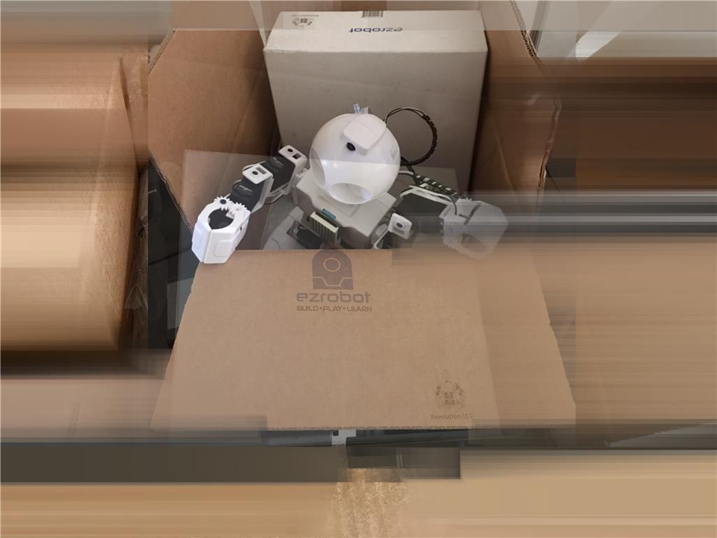

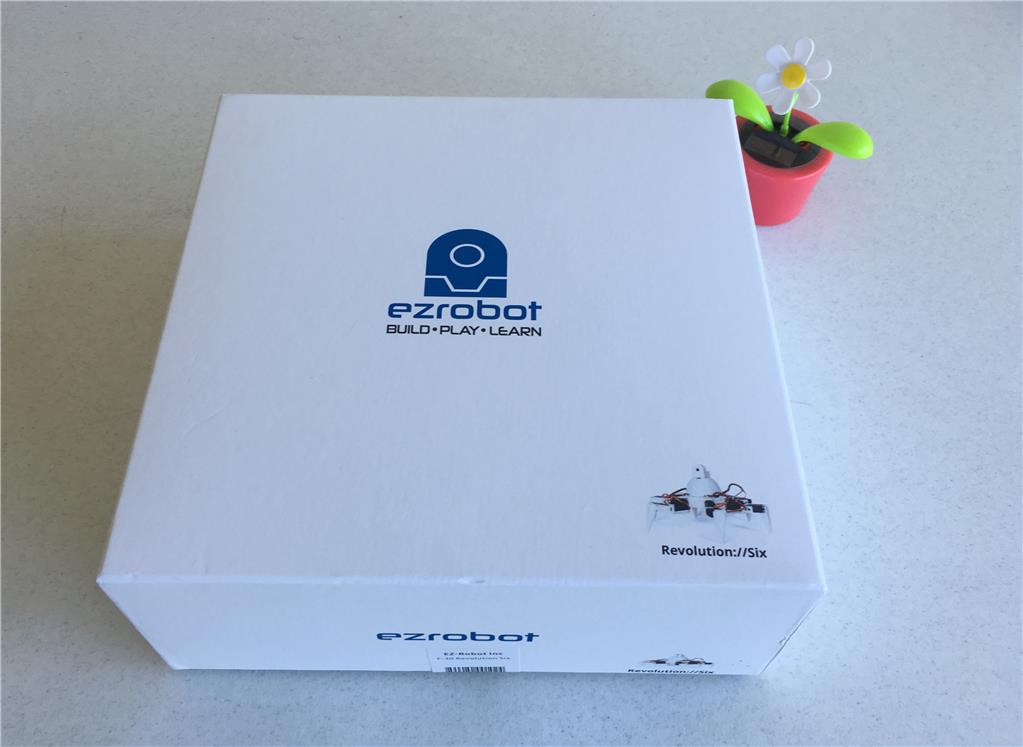
Day One: The Box
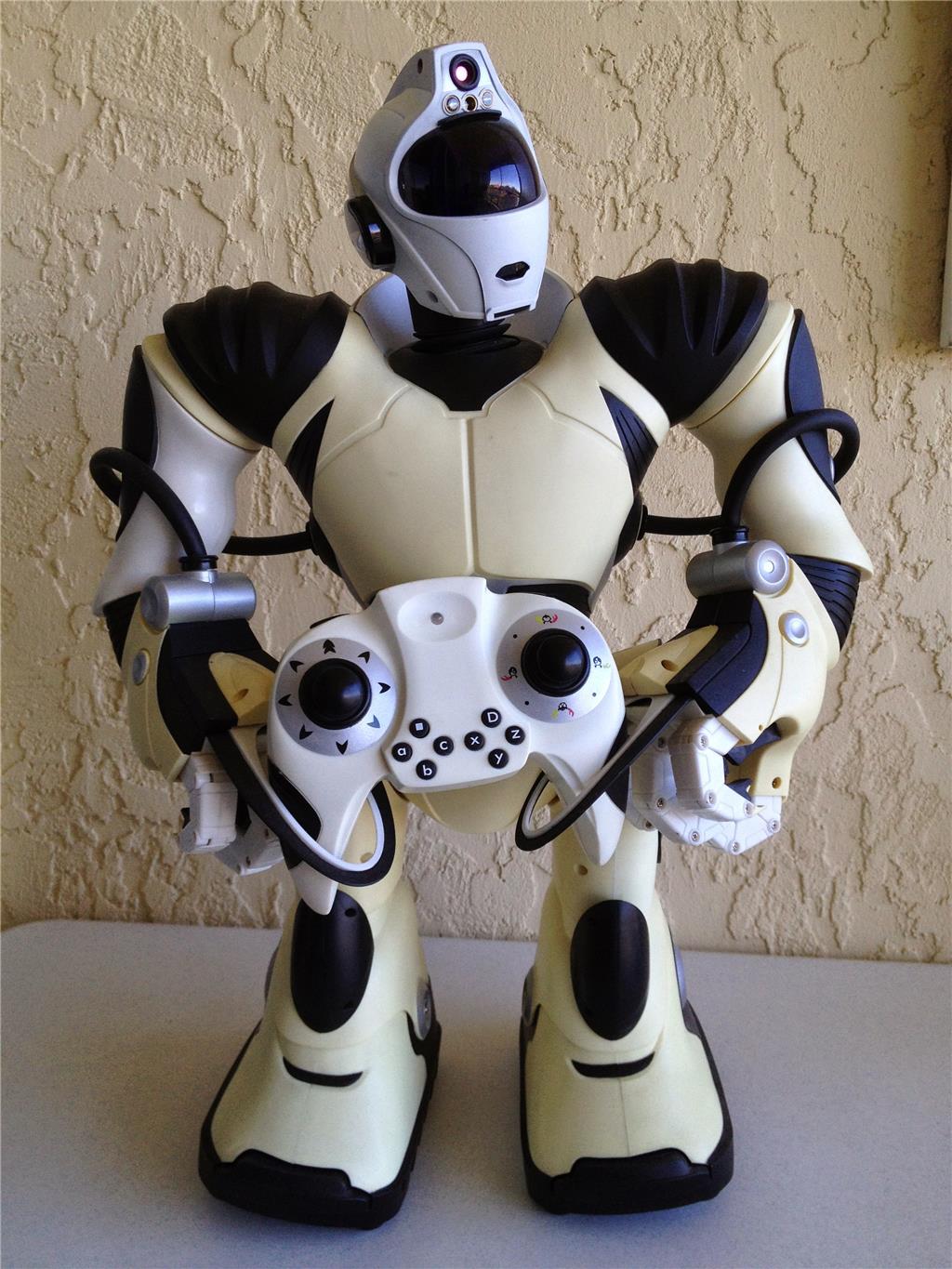
Hello, my name is Peter. I have been playing with robots for some time now. I have owned a few of the WowWee products, including the original Robosapein. I have had Roombas, Wall-Es, Robbies and many other toys. I like experimenting with Arduino circuits and have done a little with the Raspberry Pi. I owned two of the earlier EZ-Bs v.3, the Bluetooth model. Well, now it’s time I came into the revolution.
I plan to be using the Revolution Six. I hope to undergo a continual exploration of all the things I can do with this robot. And, of course report back, so that others can critique and offer comments. I expect to make quite a few mistakes, but I hope to share these, so that others can avoid some of them. I have a lot of ideas to explore. Some will be very serious and some will be very whimsical. My style is more toward exploring and experimenting that completing a finished robot. The Revolution Six is already pretty complete. My style is also very lighthearted.
All too often I see family members spent hundreds of dollars on a robot, put it together, move it across the floor and then put it away in the closet until next summer. Luckily, I get a chance to buy them at the lawn sale.
With this series of posts, I hope to continually inspire you to try new things with your robot, even if it's only for the fun of seeing things move or light up.
Discover more robots

M's Haw To Make Ez-Bv4 Controller Communicating Via Usb...
Ezang's My New Metal Robot With Voice Commands 10/25/2019

nice - that's a super fun video. glad you are enjoying the Auto Position control... it's a powerful tool!
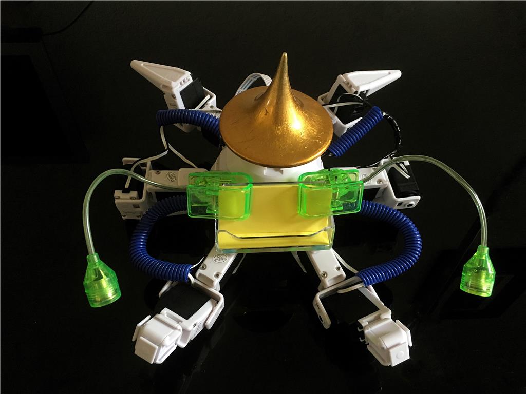
ELECTRO-PLASTIC STEAMPUNK MACHINE 02
I like that! Looking forward to seeing it live!
I am enjoying watching your experiments. Some interesting concepts.
Alan
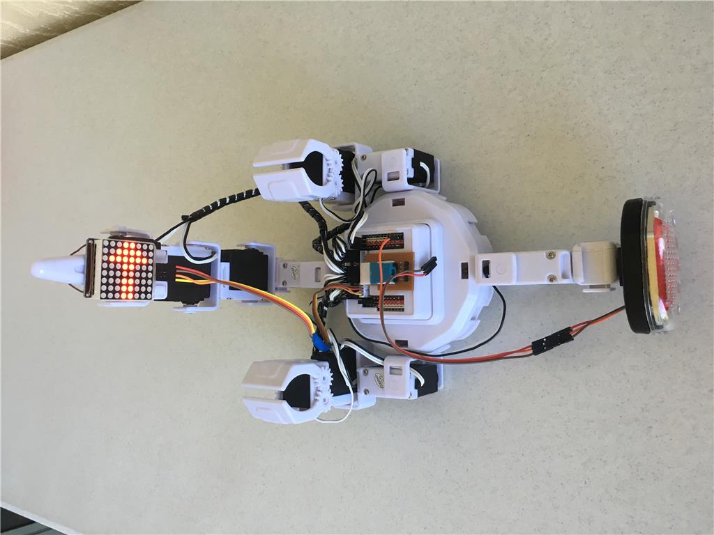
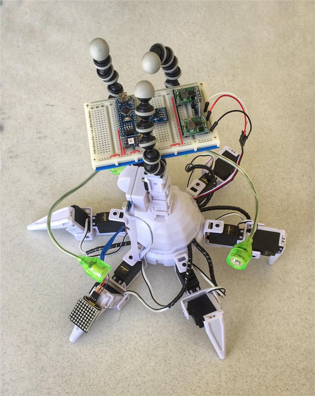
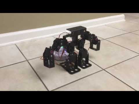
Day Four: The Six Lab
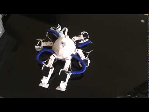
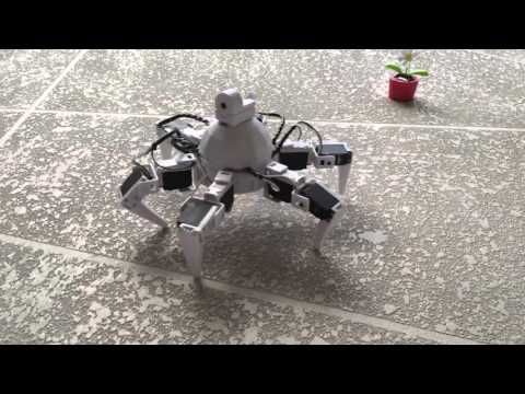
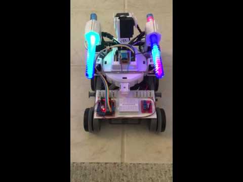
It’s time to put together a little lab where I can test out all the sensor, LED, and motor, ideas for future Electro Plastic Steampunk machines. The Six offers a good place to experiment. Take off the dome, remove a few of the appendages and you have 12 places to attach EZ bits, which in turn can have a variety of things attached to them.
I want at least:
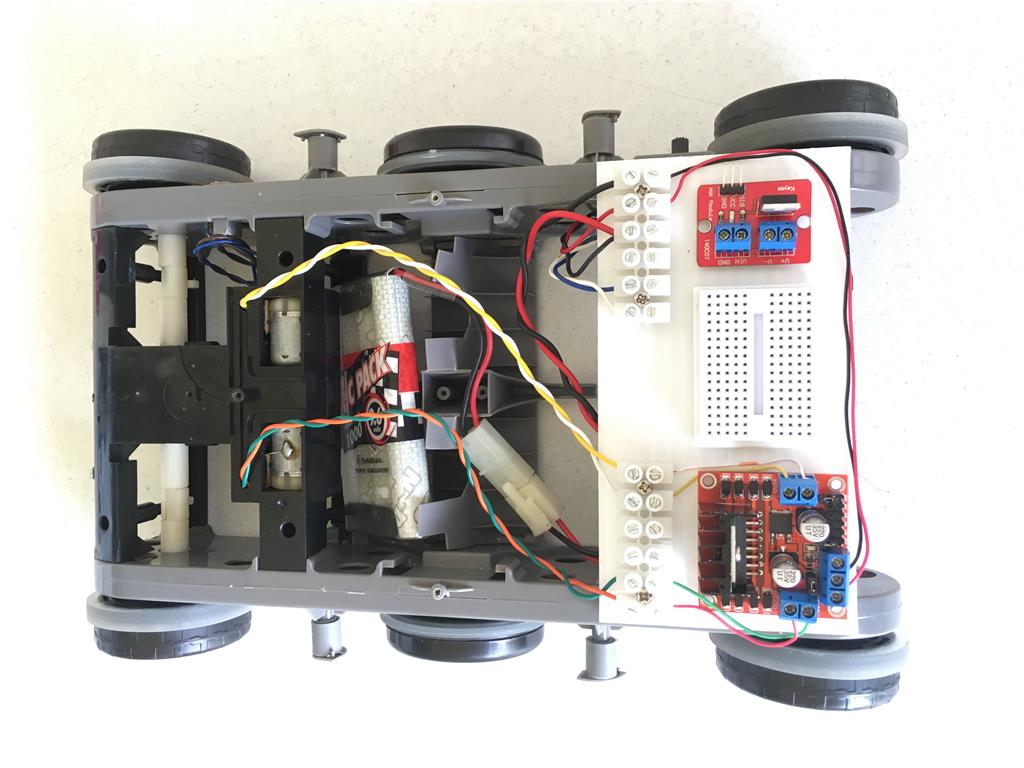
one solderless breadboard a place to experiment with the famous 37 Sensor kit PWM experiment area ADC experiment area the ability to drop voltage form 7.4 volts to 5 volts a camera with horizontal and vertical movement at least one gripper with horizontal and vertical movement one pointing finger A place for 8x8 matrix display at least one continuous rotation servo a place for my motor controller for DC motors
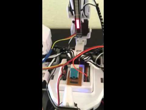
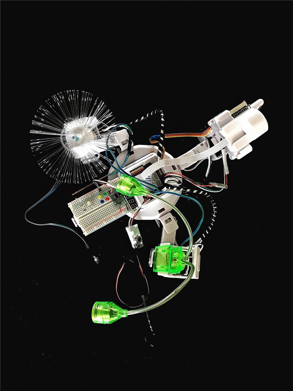
I thought I would start by redesigning a new interface and create a project called the Six Lab. This ongoing project can be found on the EZ Cloud (Public, Revolution, DIY, Incomplete) as Six Lab. Here is a picture of my version, preparing to test some LEDs via PWM.
Day Five: PWM Experiments
I enjoy doing visual things with computers and robots, like blinking LEDs and moving gauges. Sometimes the simplest controls offer an opportunity to explore in new directions. How about if I achieve the visual effects simply by means of changing the voltage.
I keep going over the tutorials, looking for new inspirations. while was looking over the lessons and I noticed the PWM control and decided using this as a good place for experimentation. Just by using the PWM control and sliding the slider I can change the voltage to alter LEDs move meters maybe other things. Let’s get started.
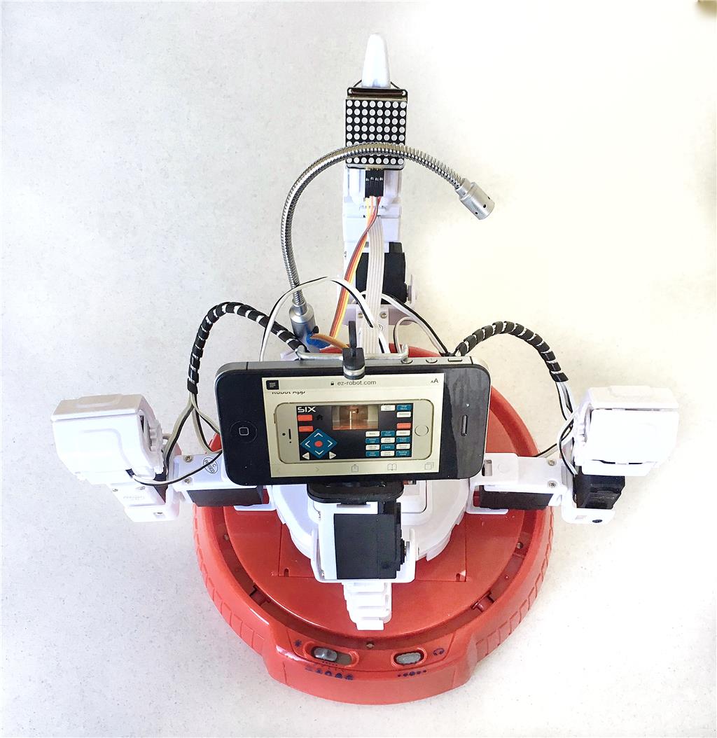
What things can undergo visual changes, making interesting robot activity by altering the voltage applied to one or more of the ports? Let's set up a little PWM lab and gather these components:
Pulse Width Modulation is very useful and fun, but I only wish I knew how to change the voltage over a greater range than three volts. Does anybody know how to do that? Anyway, on with all the different things I decided to PWM.
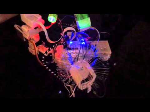
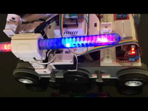
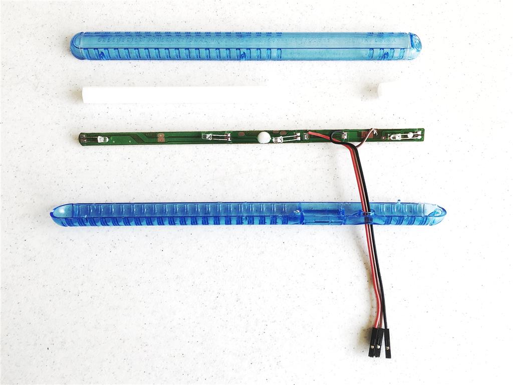
These ideas merit a trip to the dollar store for supplies. I was able to find the fiber optics (a plastic flower with one changing RGB LED, 4.5 volts), the pulsing LEDs (a pair of blinking happy birthday glasses), and the eye-possible LEDs (a cheap reading lamp - one white LED each).
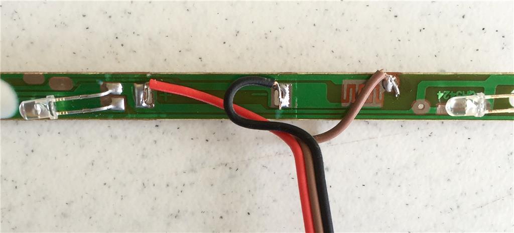
A little cutting and soldering of DuPont cables, and some bending and breaking of plastic and I have three useable PWM experimental pieces.
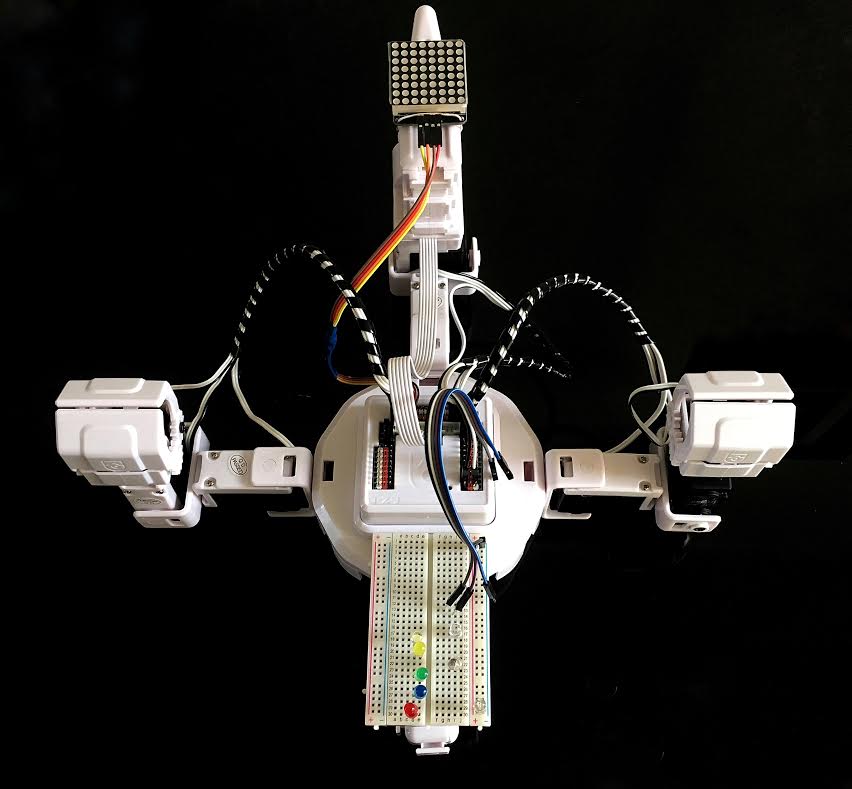
I use digital ports D3, D4, D5 and D6 for the PWM experiments. Be sure to read the tutorial in the learn section. It is a great start to Pulse Width Modulation.
Here is a photo of the finished project and a video of all the PWM accessories going at once.
Now of course pwm is not really changing the voltage, it is poweringn on and off very very fast and appears to most devices that the voltage is lower because it is not getting full voltage long enough to come up to full power (or something like that. DJ could explain better). If you view an LED getting less than 100 PWM with the EZ-B (or any digital) camera, you can see that it is actually blinking, but your eye can't see it on its own.
Alan
Digital ports logic voltage is 3.3v, the only voltage you get in a port is 0 or 3.3v.
PWM has a specific frequency depends on the Microcontroller timers, when PWM a port between 0 and 100, you are changing the duty cycle.
For example if the pwm frequency is 1 Hz (1 time per second), and your PWM is 25 you will see the LED blinking.
if the pwm frequency is 100 Hz (100 times per second) and your PWM is 25 you can't see the led blinking instead you see it less bright.
Arduinos default PWM frequency is 490Hz, and 980Hz. I have an Arm Cortex M4 and the default frequency is 480 Hz, but it depends on the micro controller clock.
i don't know the EZB PWM frequency and if it varies per version (v3,v4) but my bet is arround 500Hz.
DJ demos the pwm duty cycle: https://synthiam.com/Support?id=164