


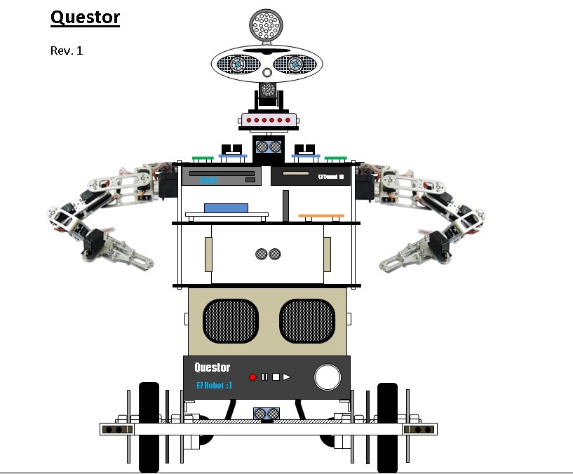
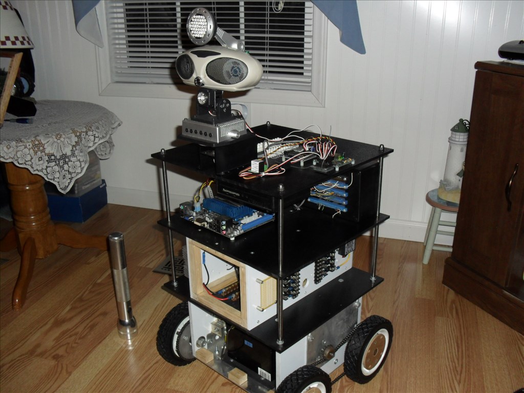
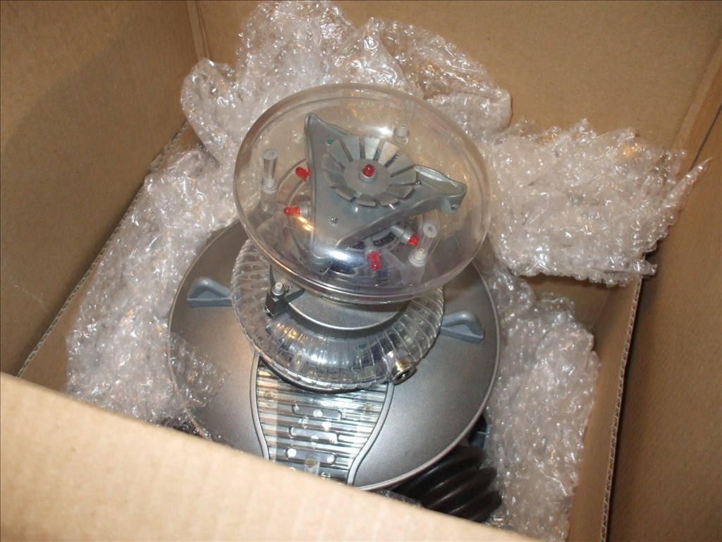
Introducing Questor.
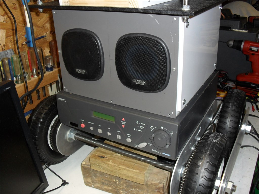
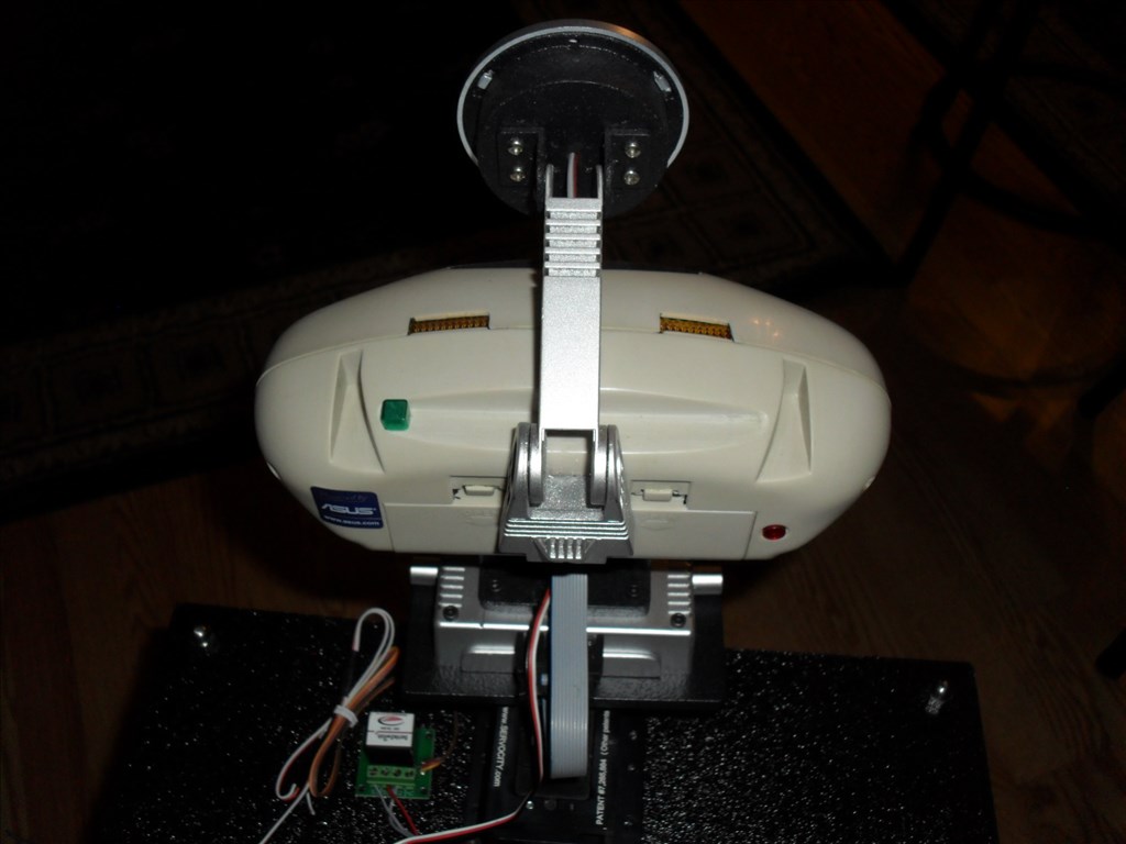
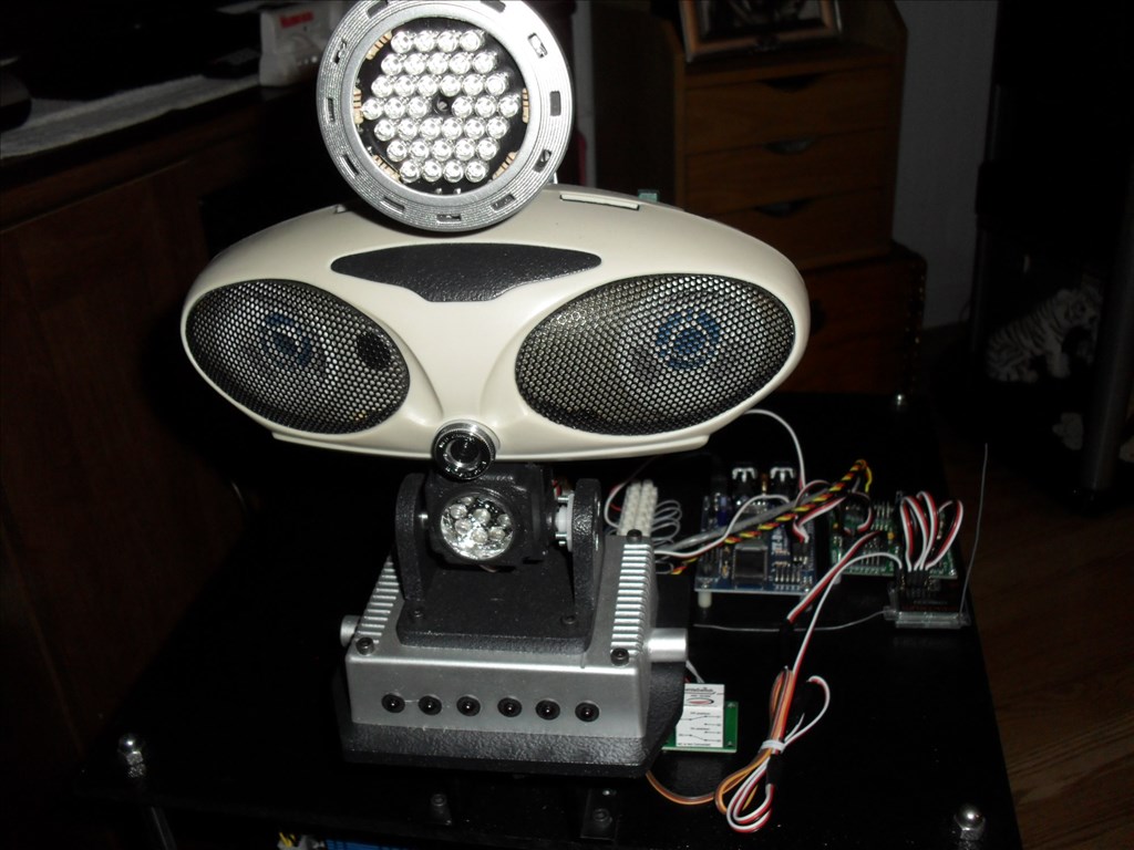
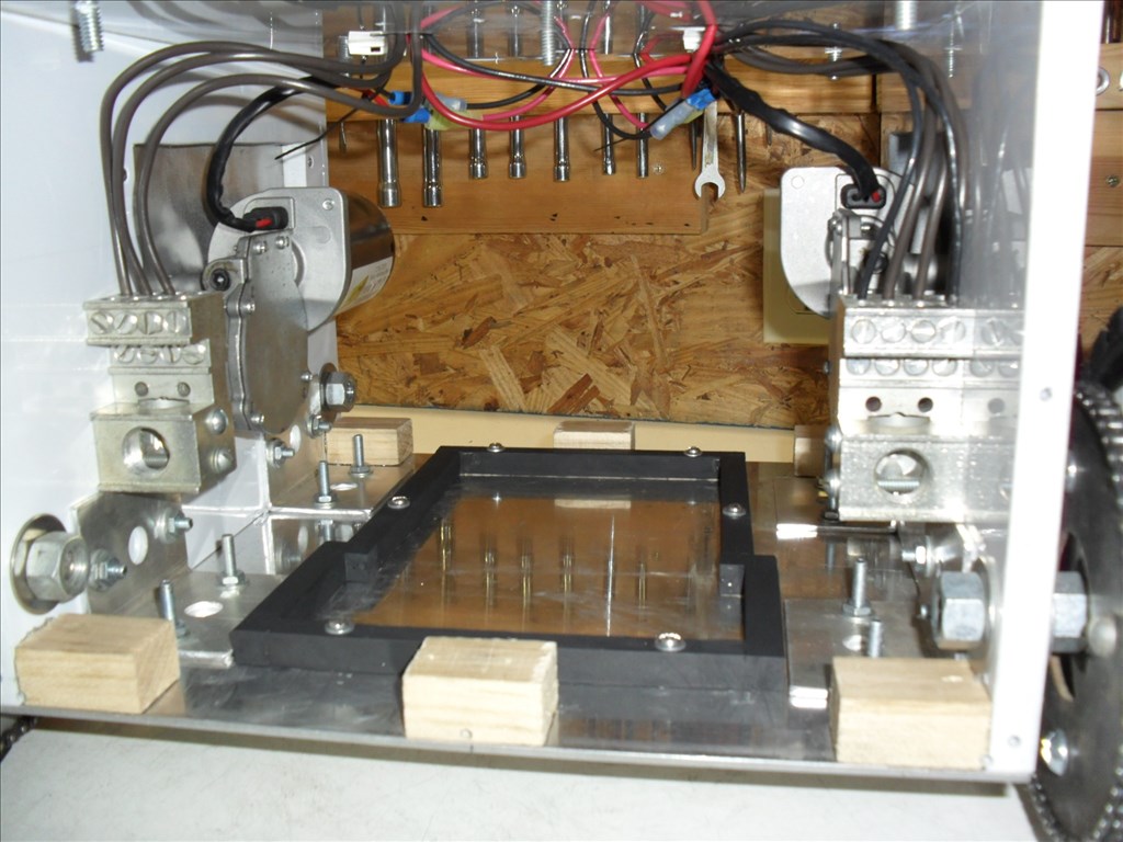
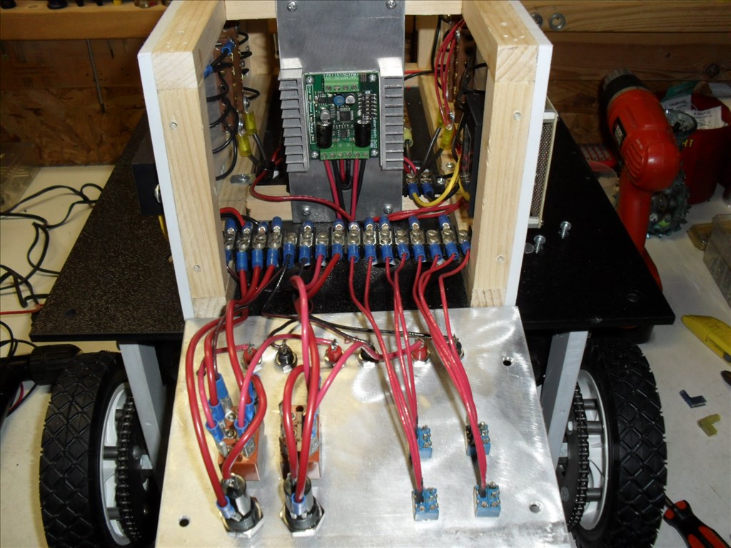
I put a hold on my large robot project Magnus awhile back due to budget and time constraints. I wanted to have a platform that was way smaller, easy to modify for testing purposes and small enough to roam around inside the house autonomously. Questor will serve as a test platform for systems that will eventually be placed in Magnus. Questor was not intended to be a cool looking robot platform, just functional and very basic in appearance. My main goal is for him to be autonomous with the option of me being able to take over remote control separately if needed. I would like for him to be able to automatically find and connect with his battery charger and to eventually have a good A.I.
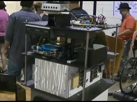
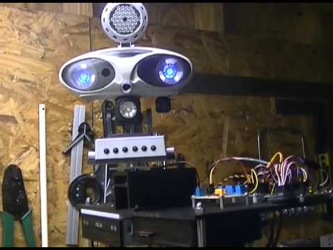
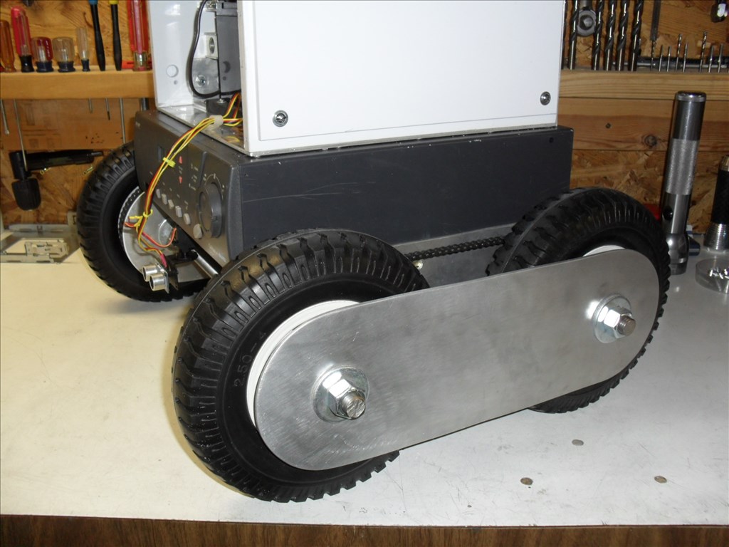
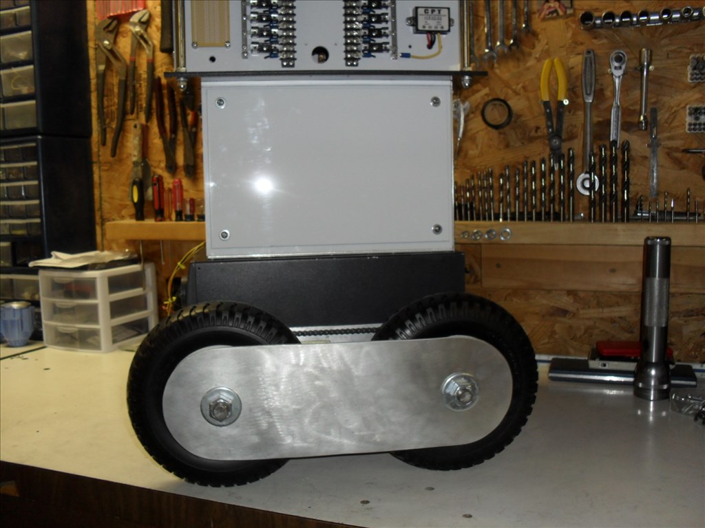
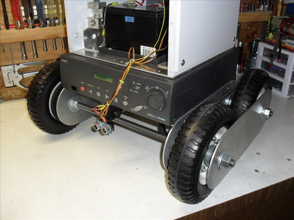
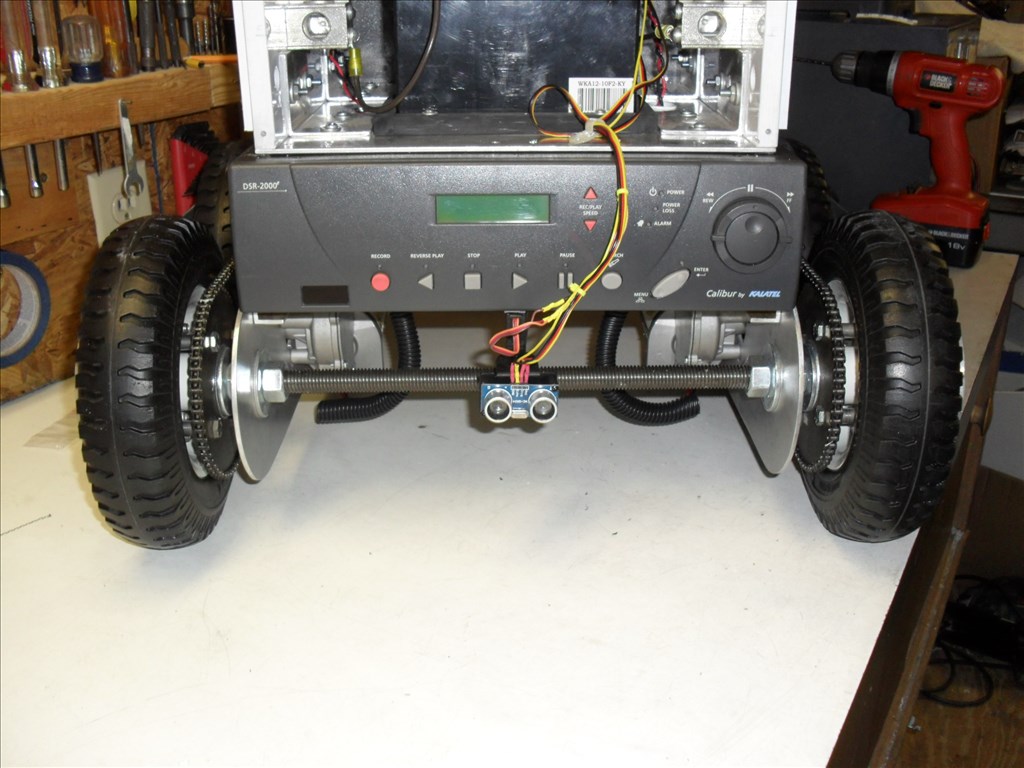
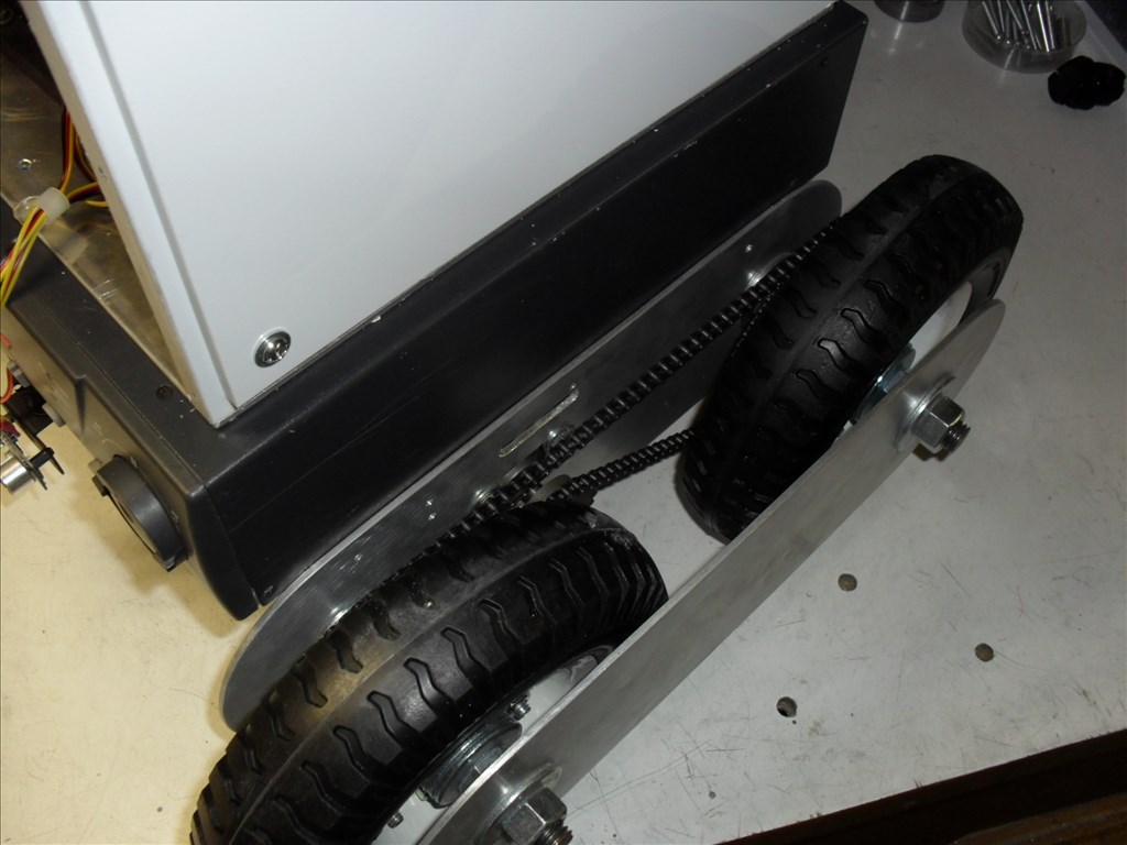
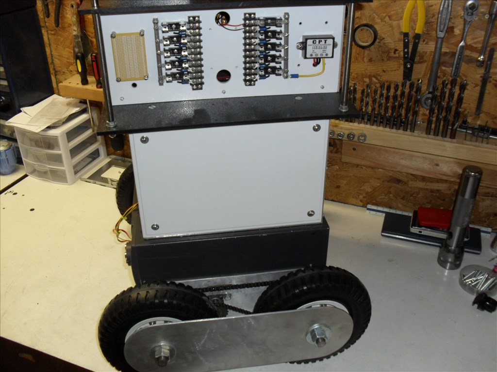
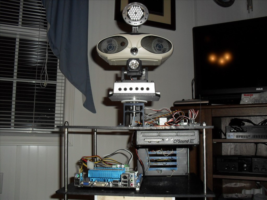
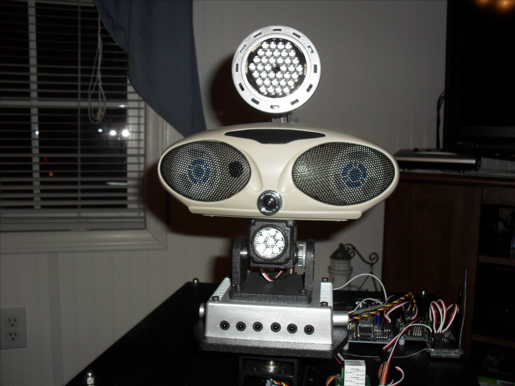
So here is a first look at him...


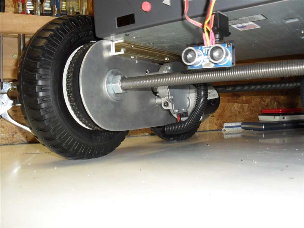
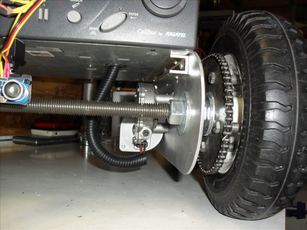
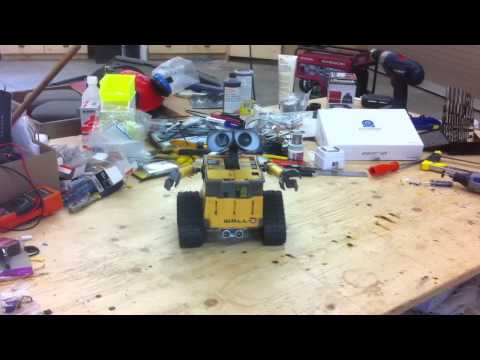
Weird....the pictures below [b]this line were not intended to be here in this first post. When I made the new post below, it saved the pictures in this post also. When I tried to go back and edit them out of this first post they don't show up on the thread so I can delete them. They belong in the post below....see details for the new wheels in the later post.[/b]
Discover more robots
Justinratliff's Mini B
Bhouston's My New Robot

The following is from another thread but I wanted to move it to this one....
I have poured over the forum and web trying to find a way to smoothly change from EZ-B control to R/C control and back again. From what I have read, it seemed others were having this issue as well. I have looked at all the tutorials and contacted Dimension Engineering, tried every possible combination of dip switch setting and EZ-B control but could only get it to work in one or the other but, not both...until now.
I decided what I needed was a way to electronically select between two dip switch settings. A sort of dip switch configurator (for lack of a better term). So I searched until... I think I found the end of the internet.
Maybe I missed something but there did not seem to be one available...so I did what any good robot nerd would do...I built my own.
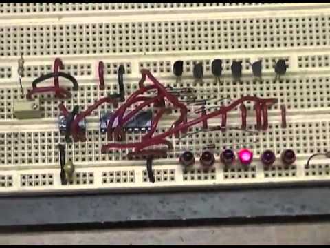
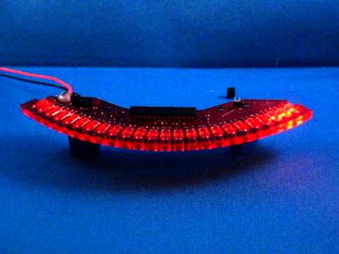
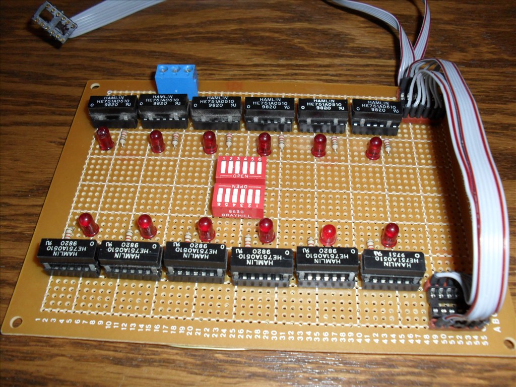
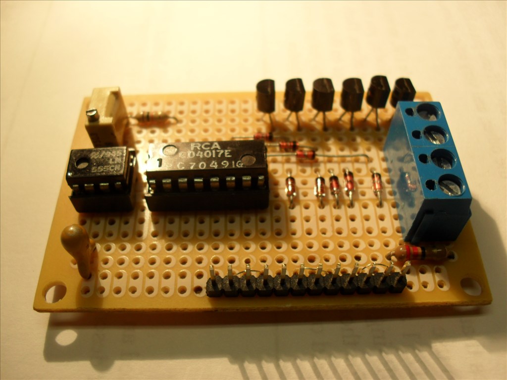
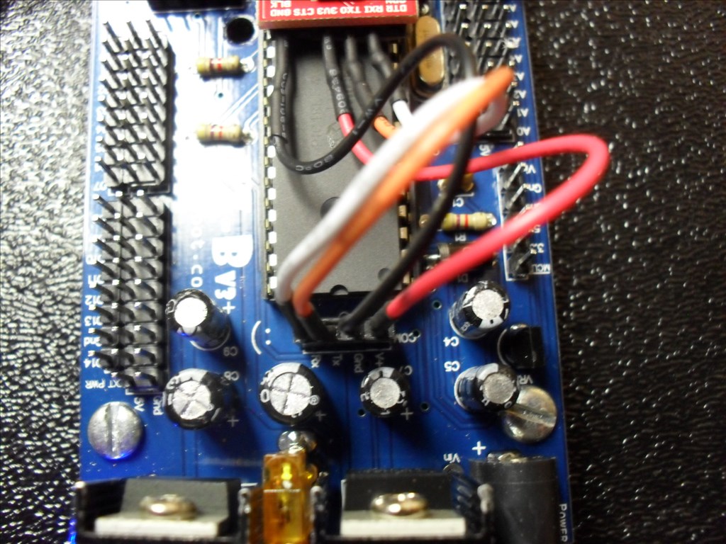
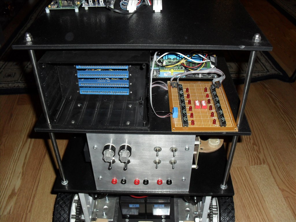
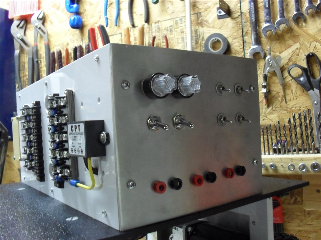
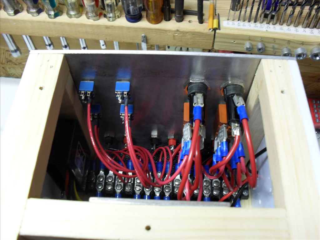
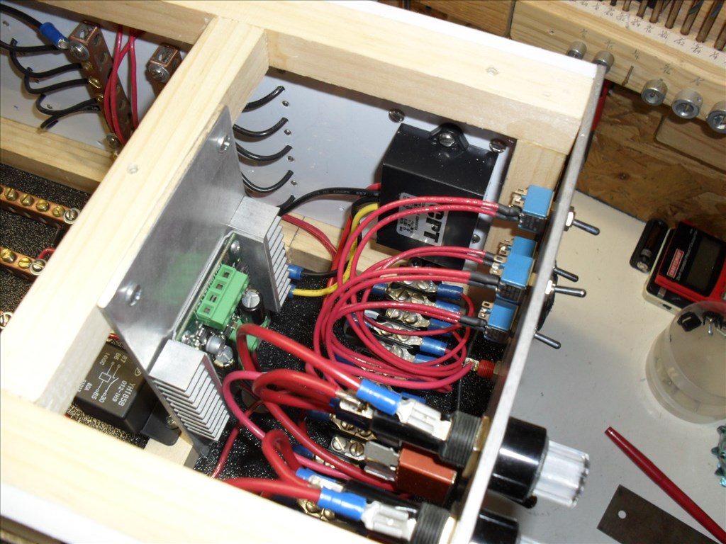
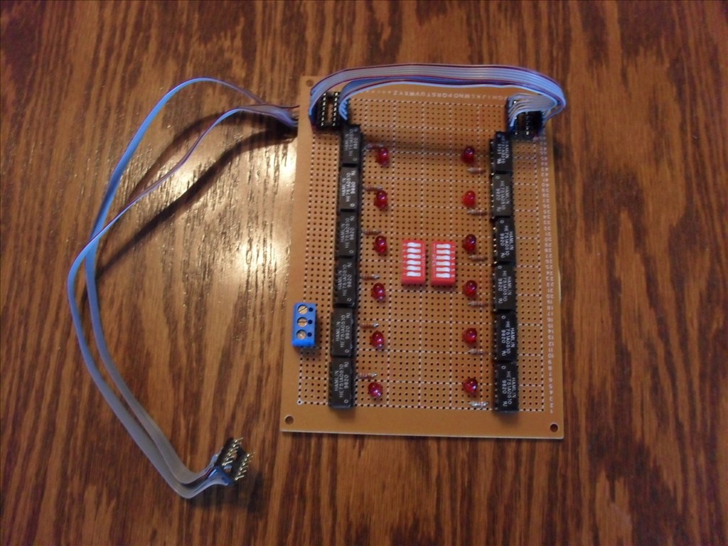
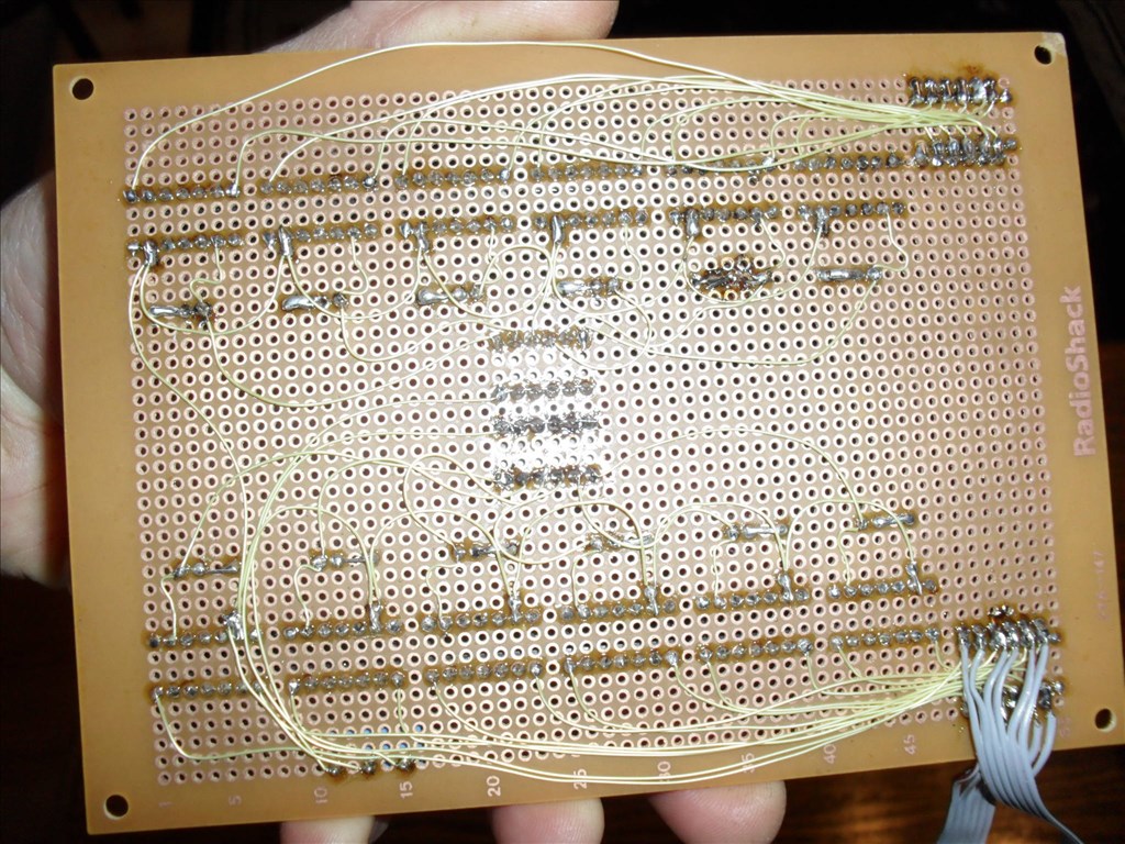
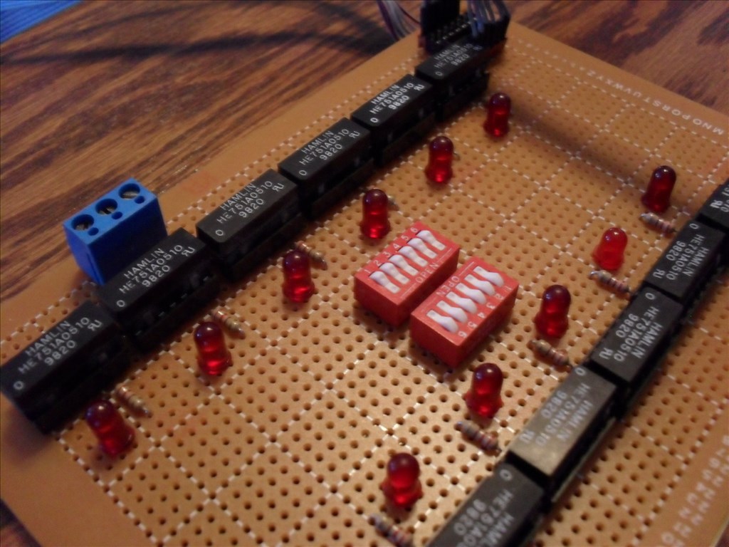
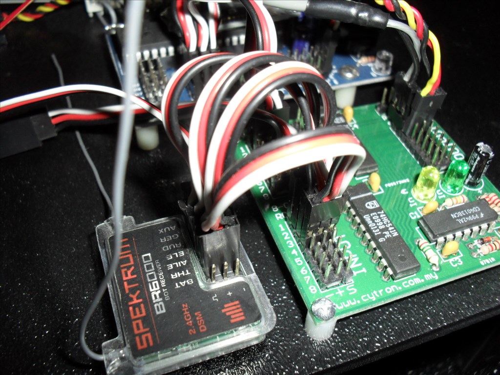
I used tiny HE751A0510 reed relays with normally open, SPST (ie. single contact). The ones I had on hand happened to have 5V coils with a suppression diode. For now, I constructed it on a perforated circuit board. Eventually I will try to miniaturize it further and etch my own board. There are two separate circuits. Each circuit has six relays and one six position dip switch. Each relay contact represents one dip switch position "on the Sabertooth". Each relay has its own L.E.D. to indicate when it is activated. The dip switch on the circuit board is used to energize a relay or can be left off if need be.
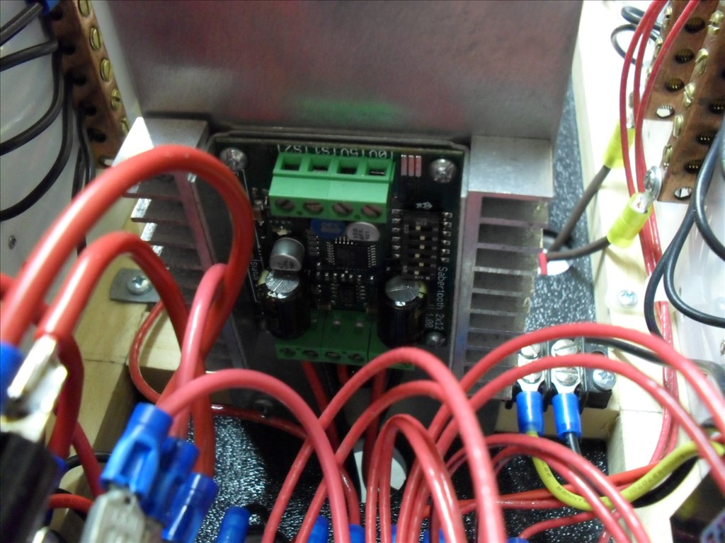
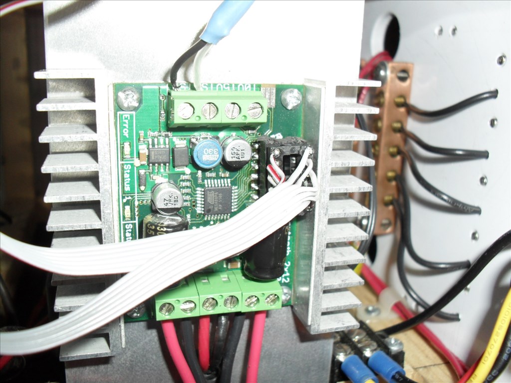
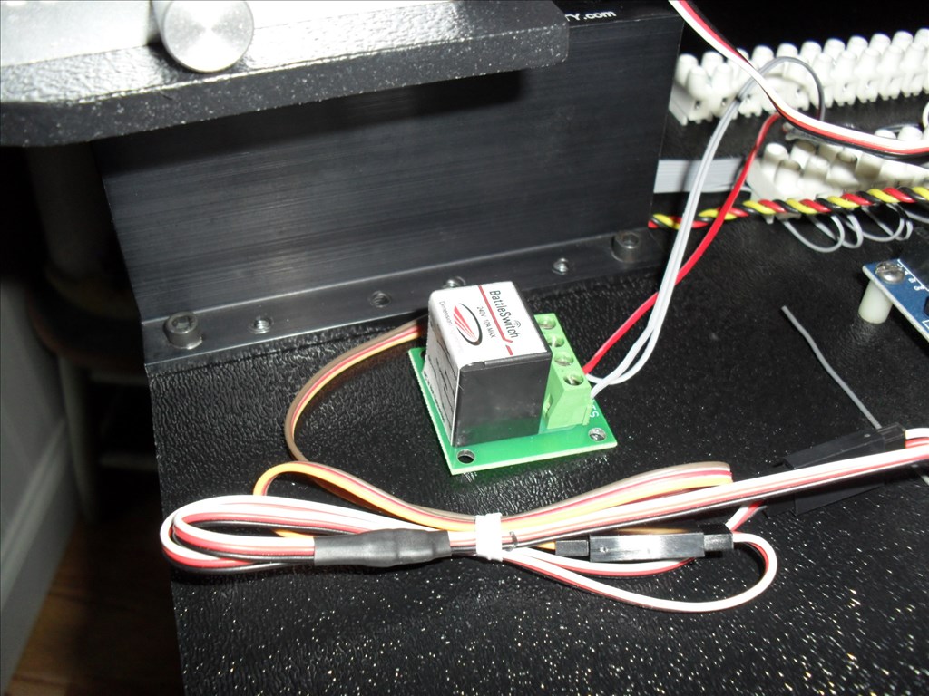
Now the tricky part. I had to de-solder the surface mount dip switch that is on the Sabertooth. I had quite a time to get it to come loose. I used solder wick to soak up the solder off of each tiny pad and finally it popped loose. None of the dip switch legs go through the board. I placed a small bit of fresh solder on each pad. I then took an IC chip socket and cut it down so it only had six pins on each side. I bent each leg so that it was shaped like a tiny foot. I pre-tinned each leg with solder. (This makes soldering easier and quicker). I placed the socket on the Sabertooth pads and proceeded to solder each leg in place. I used another IC socket and some ribbon cable to make a jumper from the board to the new Sabertooth socket. I needed a way to remotely switch between the two circuits so I purchased a Battle Switch from the Robot Market Place web site. It is an R/C controlled SPDT relay. You just hook it to one of your (on/off) R/C receiver channels. I chose the AUX channel that is normally used for R/C airplane flaps. The AUX channel is toggled on/off via a switch located on my Spektrum DX6 transmitter. I installed a three position terminal block on my dip switch configurator board. I hooked 5V to the common terminal on the Battle Switch relay and ran wires from its two contacts to the dip switch configurator board three position terminal block and hooked the two 5V wires to the outer terminals and GND (common) to the middle terminal. Each of the circuits share the GND connection.
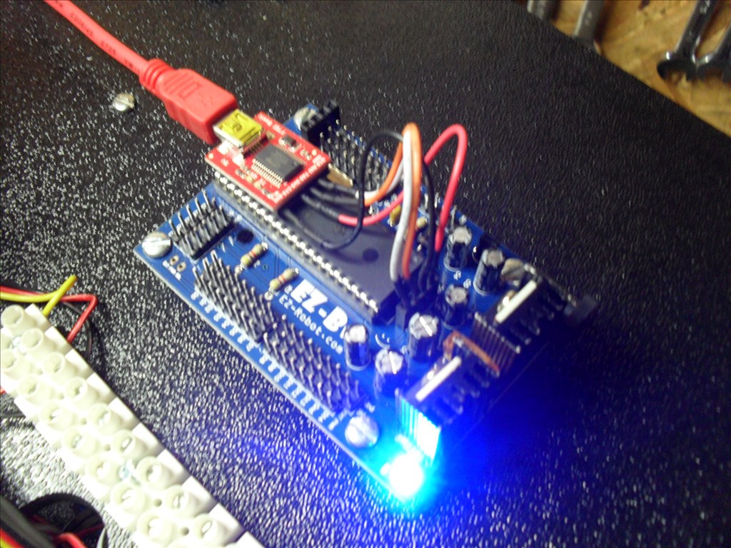
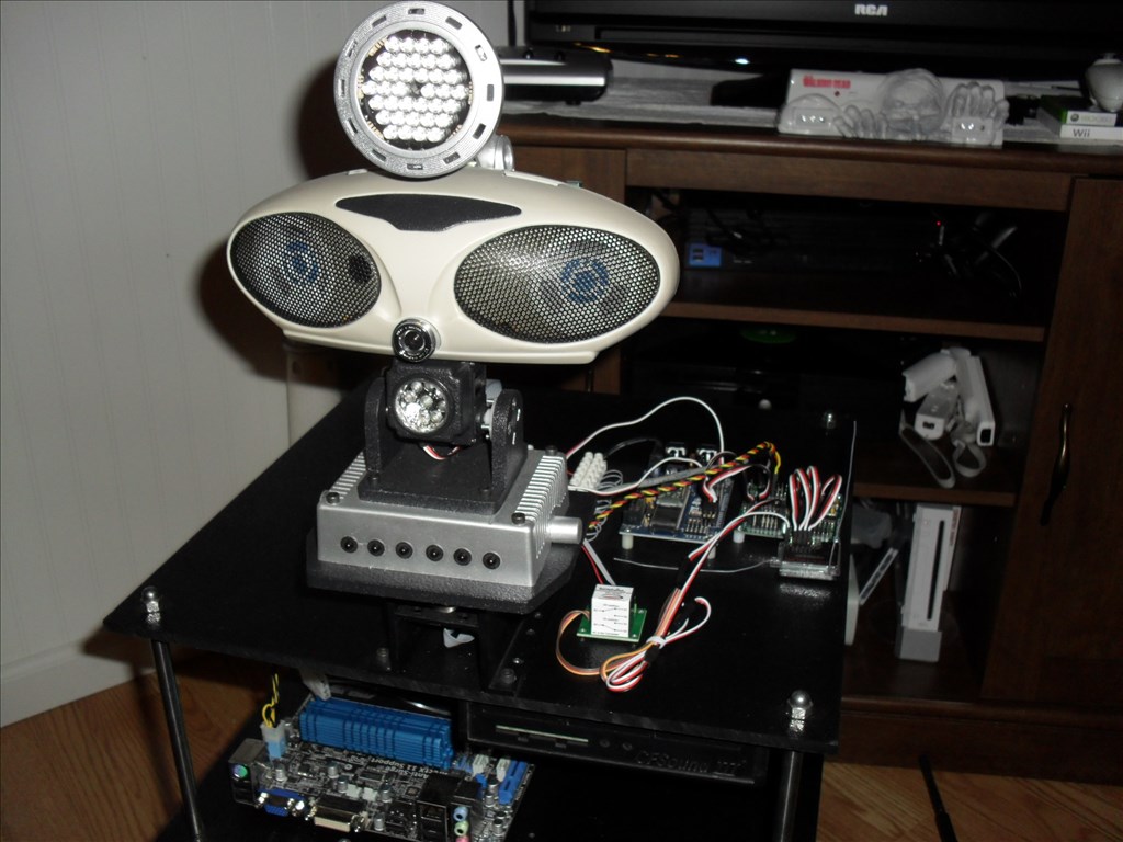
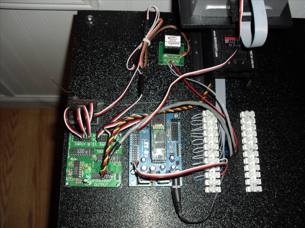
Also I have installed a R/C Mux circuit from RobotShop.com. It has two 8 channel inputs and one 8 channel output that allows me to hook all of the R/C receiver channels to its "B" input terminals and the Digital out from the EZ-B that I am using for the Simplified serial to the Sabertooth and the Digital out(s) I am using for the Head pan and tilt servos to its "A" input channels. The 8th channel of the "A" input is used (defaulted by the manufacturer) to select which inputs go to the output. If no signal is detected on this channel all of the "A" inputs got to the outputs. The AUX channel from the R/C receiver that goes to the Battle Switch relay is also hooked to this channel 8 via a Y- cable.
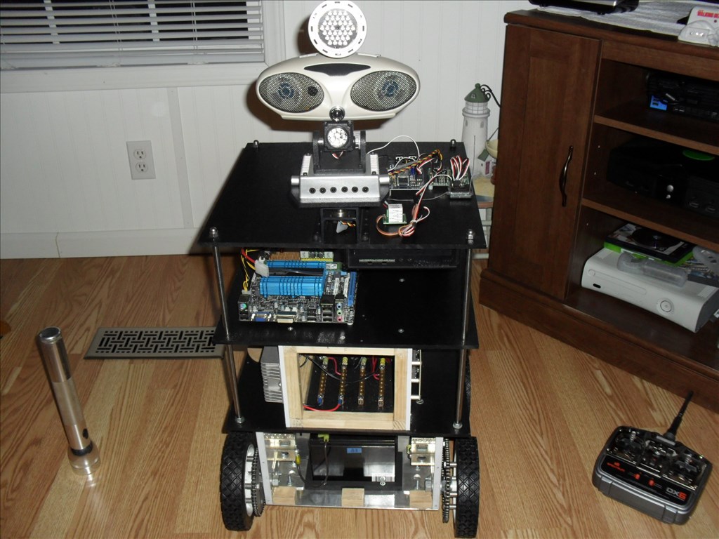
So now with the flick of a single switch on the Spektrum DX6 it will smoothly set the Sabertooth dip switch setting to whichever I need for control; EZ-B control or Spektrum R/C control. BTW the Spektrum DX6 has an approximate range of 3000 ft. It does not have to be this model. You could use most any R/C transmitter as long as it has at least one on/off channel and a few other normal servo channels to drive and steer with.
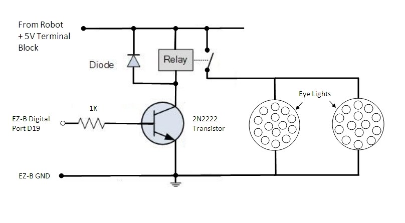
I know all of this sounds complex when describing it but, it will make sense when you see the schematic and photos (and hopefully a video).
Dip Switch Configurator Board
@Rgordon anyone is welcome to bring a robot and individual robots do not need to be registered just the booth and us. I think this will be a cool addition. Are you OK with periodic demonstration of your robot?
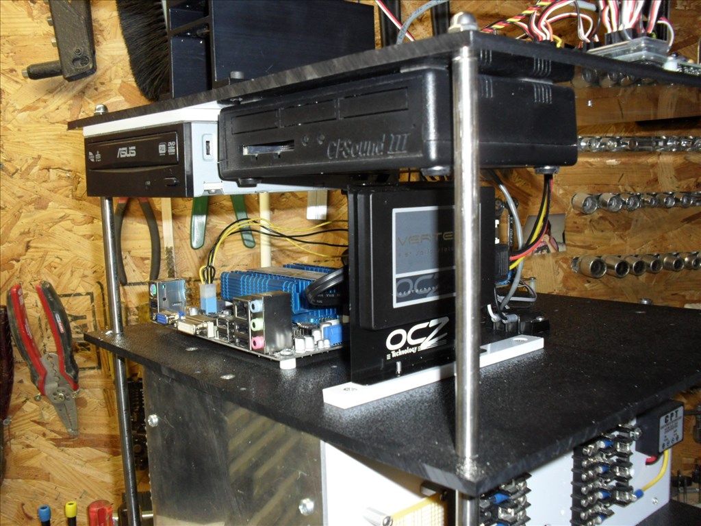
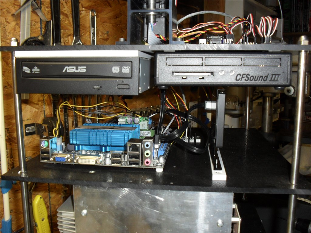
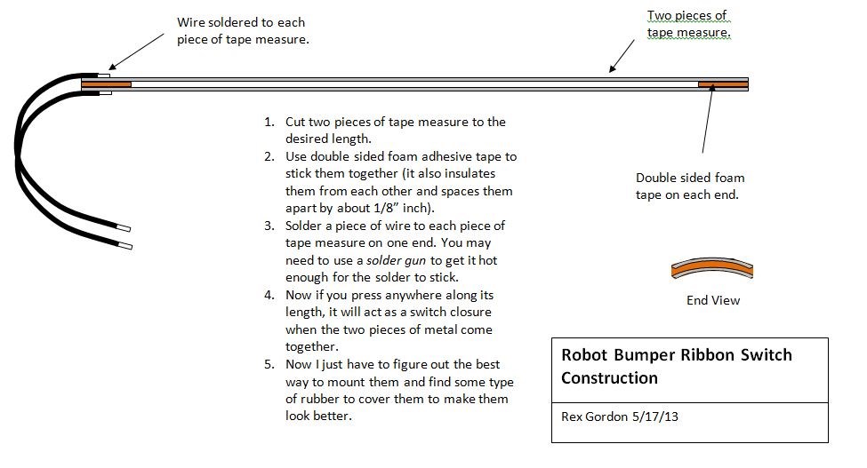
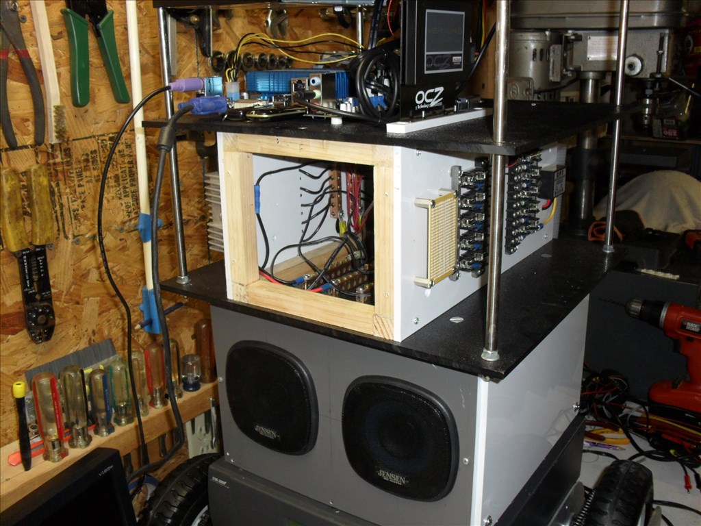
Is your DVD drive and card reader double sided taped to the upper deck? I'm starting to understand the bumper arrangement you were trying to get me to understand. So its sections of tape measure with no paint as a mechanical switch.
Wow, this is a platform of awsomeness. As a matter of fact it is epic. Great job.
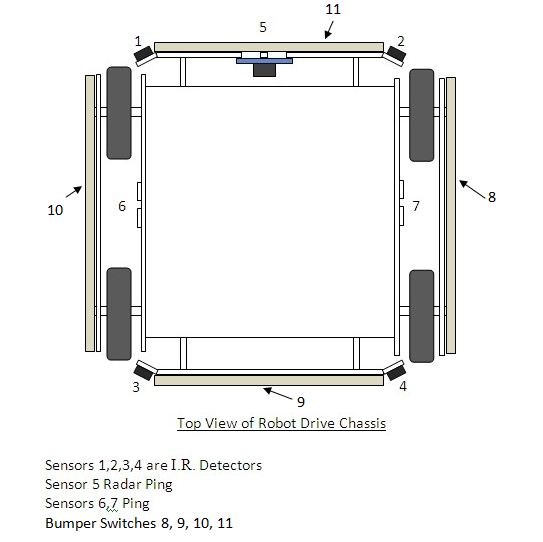
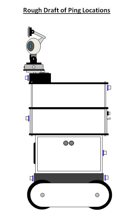
Yeah, I'd be OK with a periodic demo. Radar ping is functioning so he can avoid obstacles in his path. However, for now that is the only NAV sensor he has.
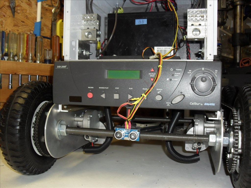
The CFSOUND III is double sided taped to the upper deck. The DVD drive I wanted to be able to remove if needed so I cut a piece of 1/4" thick (white)plastic, drilled and tapped holes in it so it could be mounted under the deck then used double stick tape to stick the drive to the piece of (white) plastic. Now just have to remove 4 screws and I can take it off. Don't know if the DVD drive will survive being mounted on the robot but, it was only $20 so worth a shot.
I have only made a prototype of the bumper switch using two pieces of tape measure with the paint stripped off. Basically it's just two pieces of flexible metal that make contact (continuity) wherever you press them together anywhere along their length. Then they snap back when you let go. Makes a great strip switch. Just got to figure out how to cover them and make them look good.
Thanks PJ_Dtechy.
Really nice work! I appreciate the work that goes into building a large scale robot. I've started construction of the next version of my ARMadeus series. Parts of the Mk. 8 will be completely different than any of its relatives. I'll be posting pictures of the build later this summer.
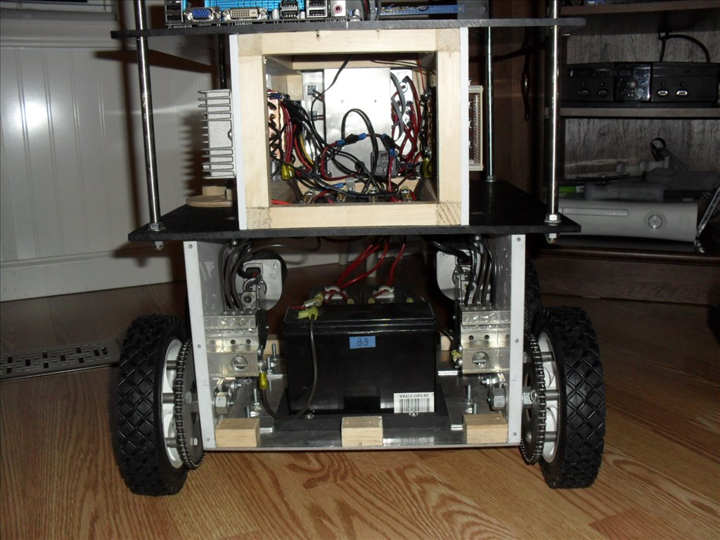
Thanks Jim, I appreciate that. I wish I had the time and money and tools to make robots as professional as you. Mine is just kinda thrown together. Hopefully, once I get it all working I can go back and clean up some of the wiring mess. But in the end this is just a test platform anyway.
BTW, Your robot is a work of art. Where do you live? I live near Buggs Island Lake (Kerr Reservoir)close to Clarksville, VA.
Rgordon, thanks. Building robots is part art and science. I do spend a lot of time planning and optimizing the arrangement of components. Using the 80/20 aluminum extrusions as the primary building material allows me the flexibility to fine tune the design and placement of the robot subsystems during construction. For me the process is highly iterative. I use off the shelf parts whenever possible. Any custom parts, such as mounting plates and brackets, are made with a band saw and a drill press. The end result is a robot with a rugged, industrial look.
I live in southern Maine, not yet a hotbed of technology. The growing number of FIRST Robotics teams in this area is helping to change that situation. I encourage robot builders of any skill level to check out a local FIRST team. It is a great way to share the passion and learn from the experience of others.