


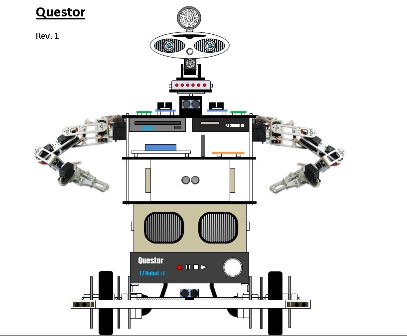
Introducing Questor.
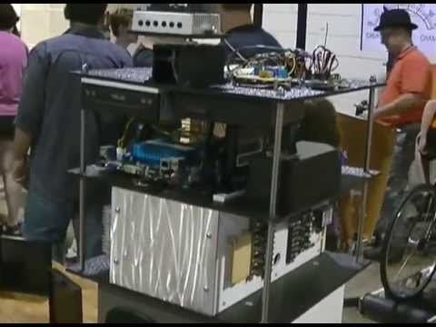
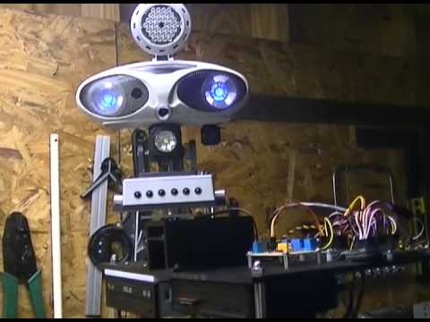
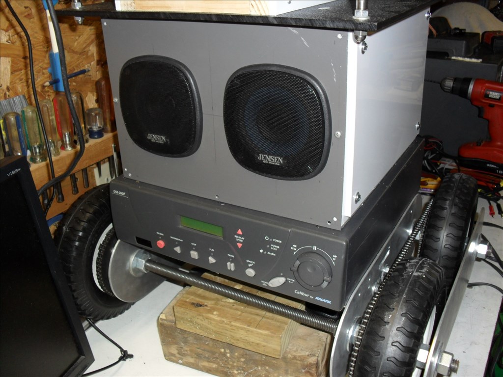
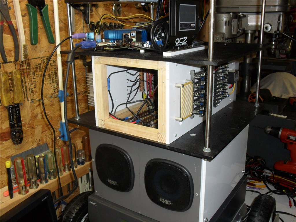
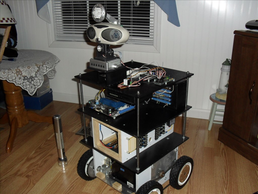
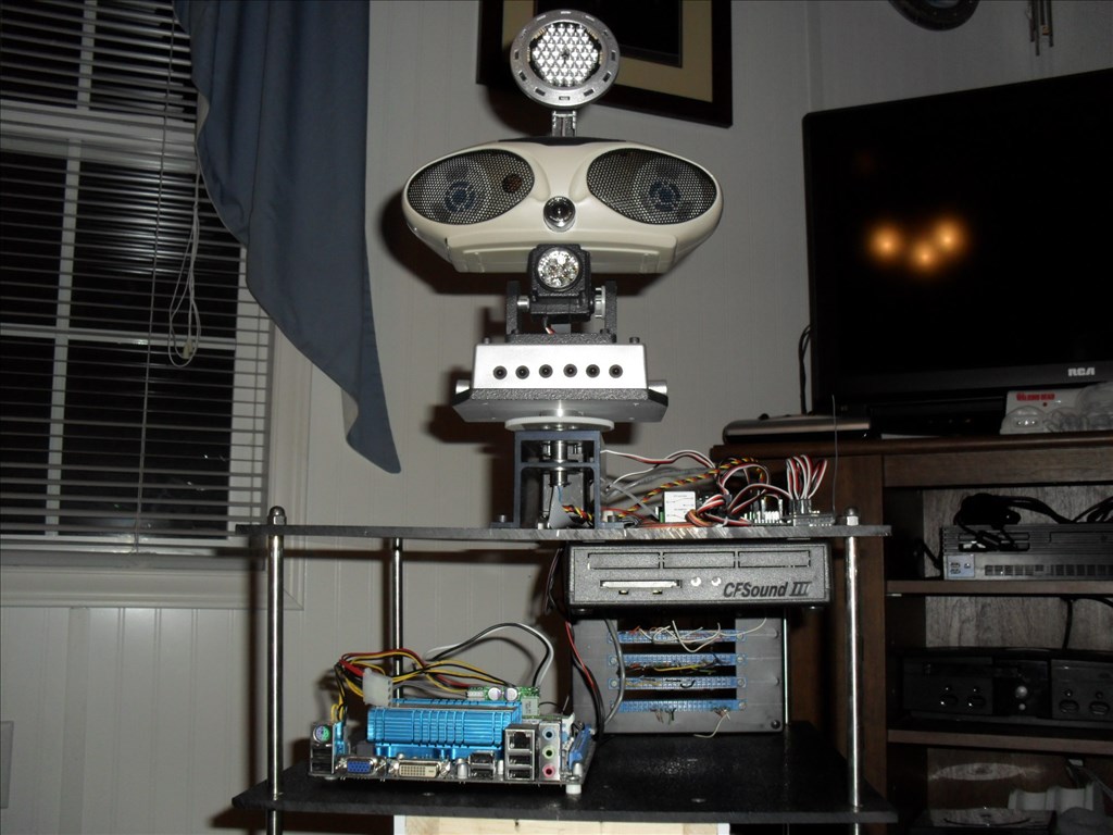
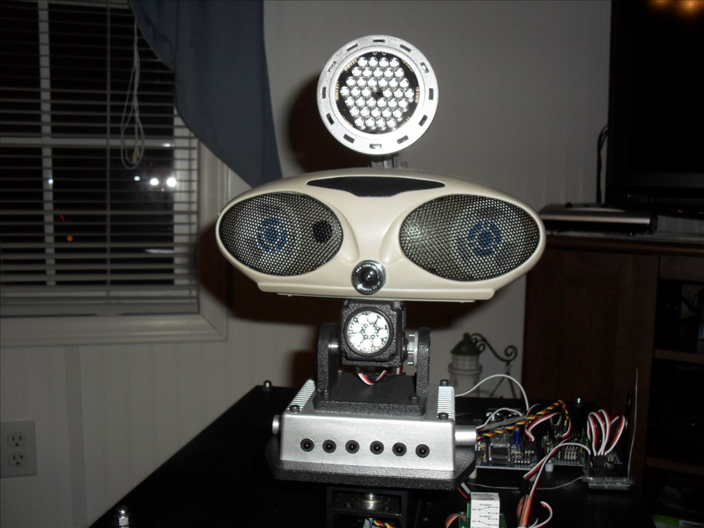
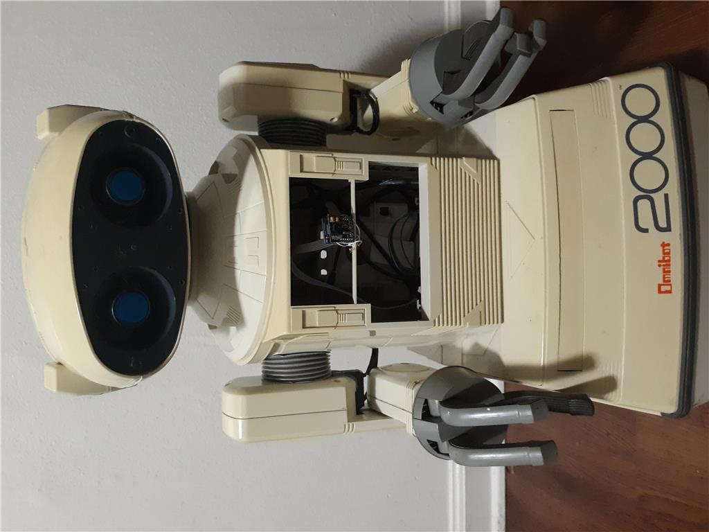
I put a hold on my large robot project Magnus awhile back due to budget and time constraints. I wanted to have a platform that was way smaller, easy to modify for testing purposes and small enough to roam around inside the house autonomously. Questor will serve as a test platform for systems that will eventually be placed in Magnus. Questor was not intended to be a cool looking robot platform, just functional and very basic in appearance. My main goal is for him to be autonomous with the option of me being able to take over remote control separately if needed. I would like for him to be able to automatically find and connect with his battery charger and to eventually have a good A.I.
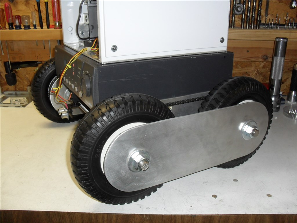
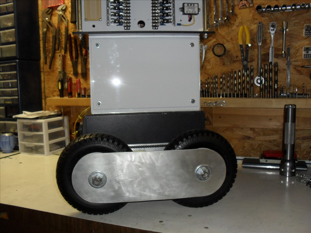
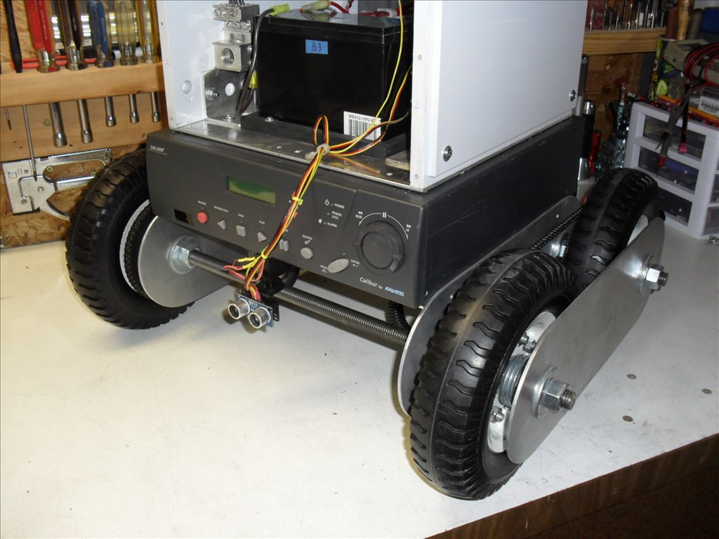
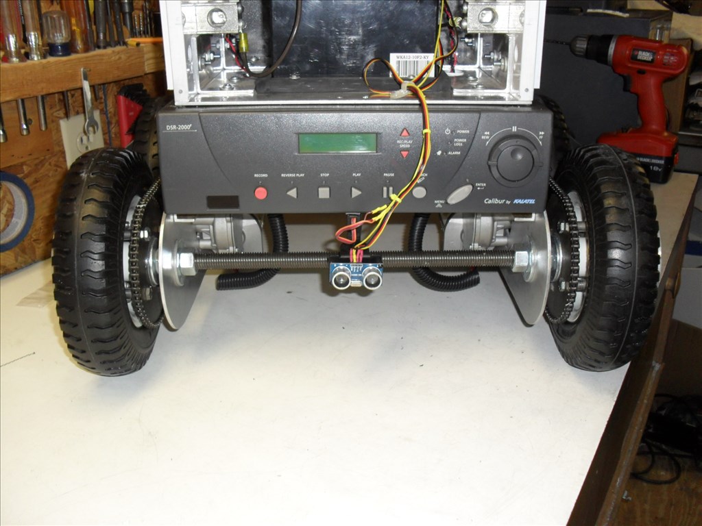
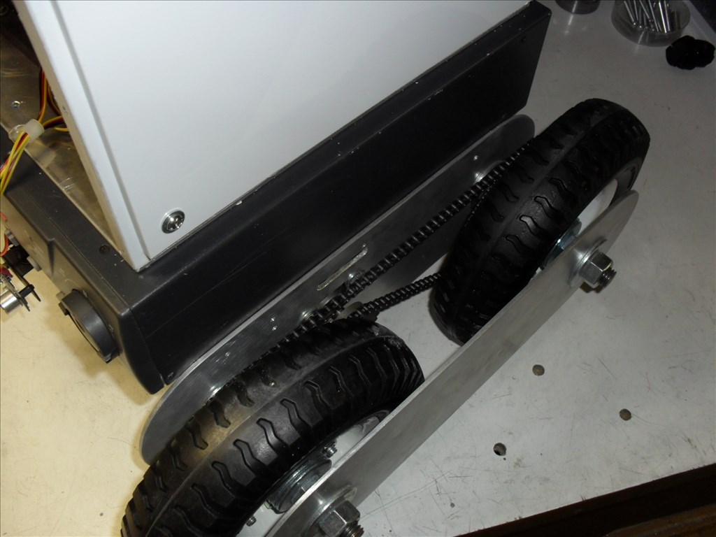
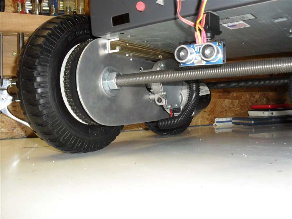
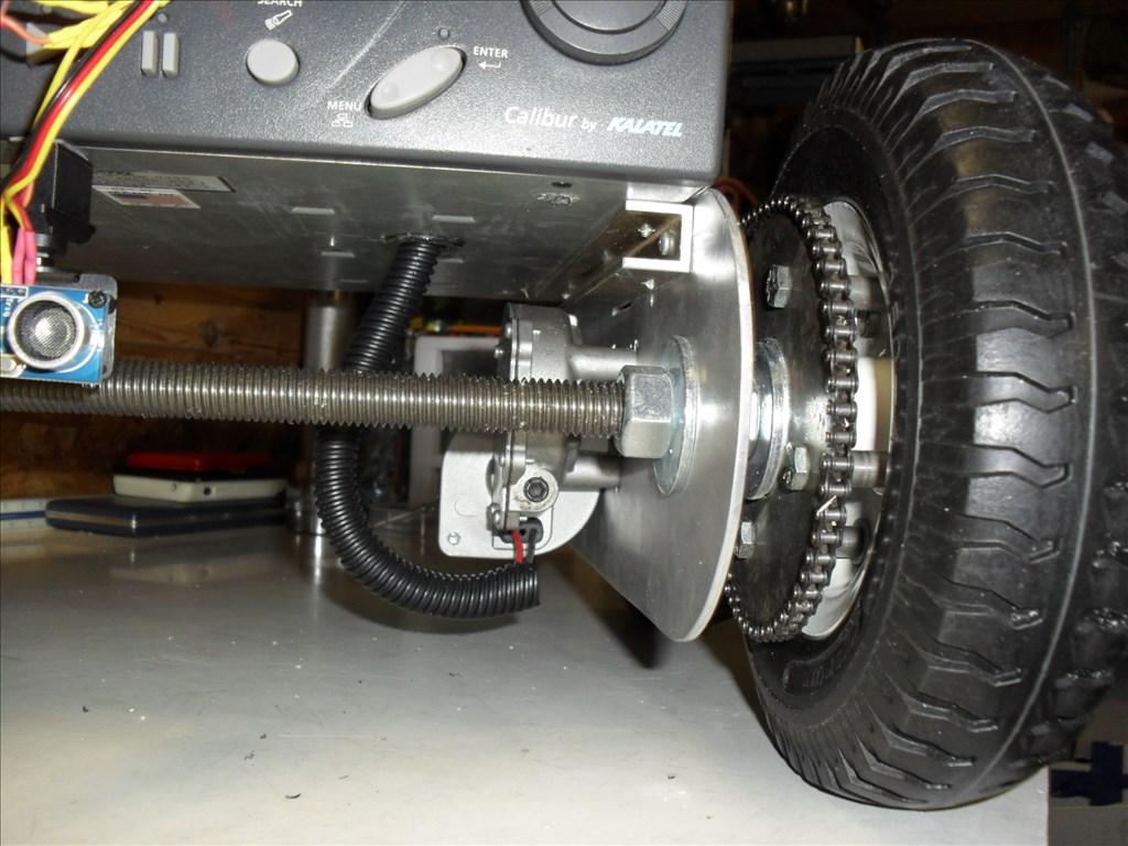
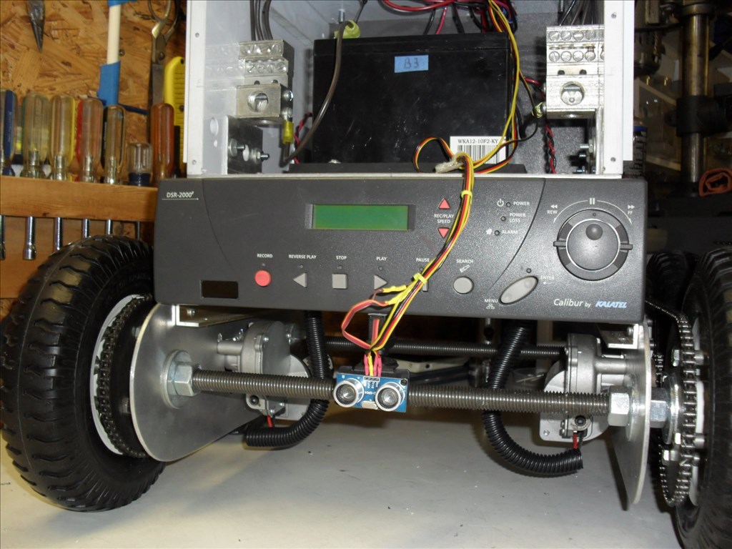
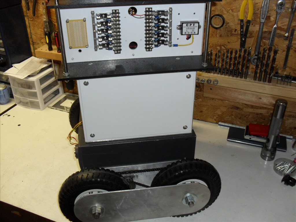
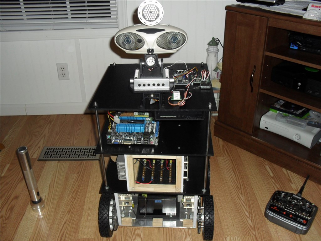
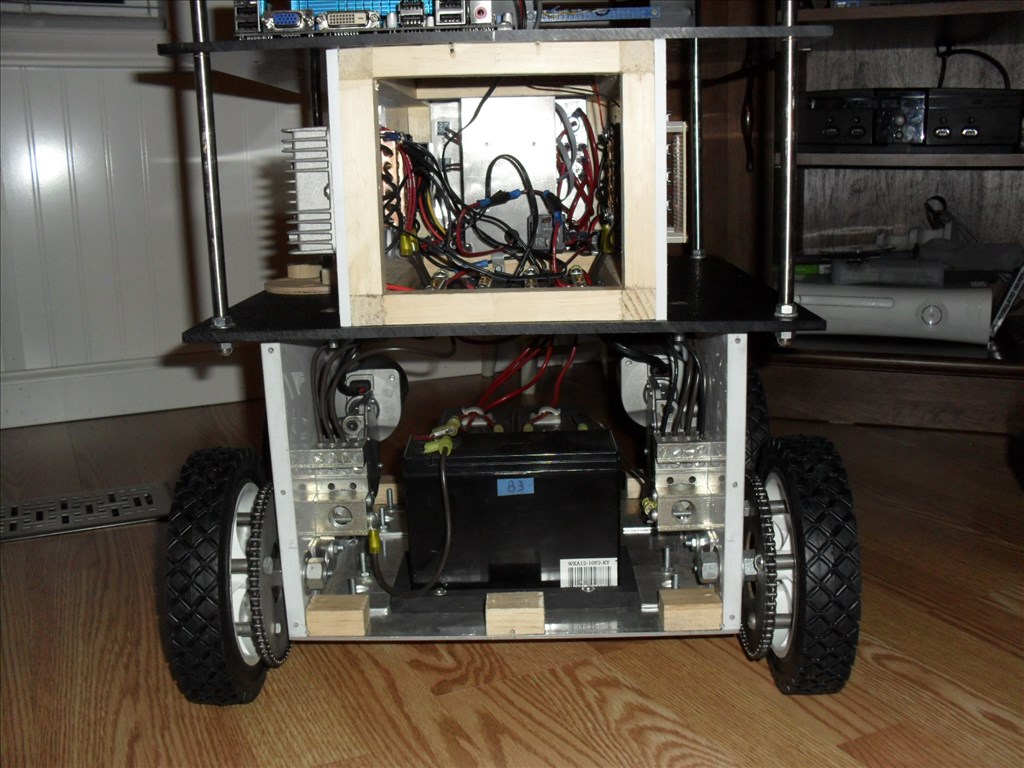
So here is a first look at him...

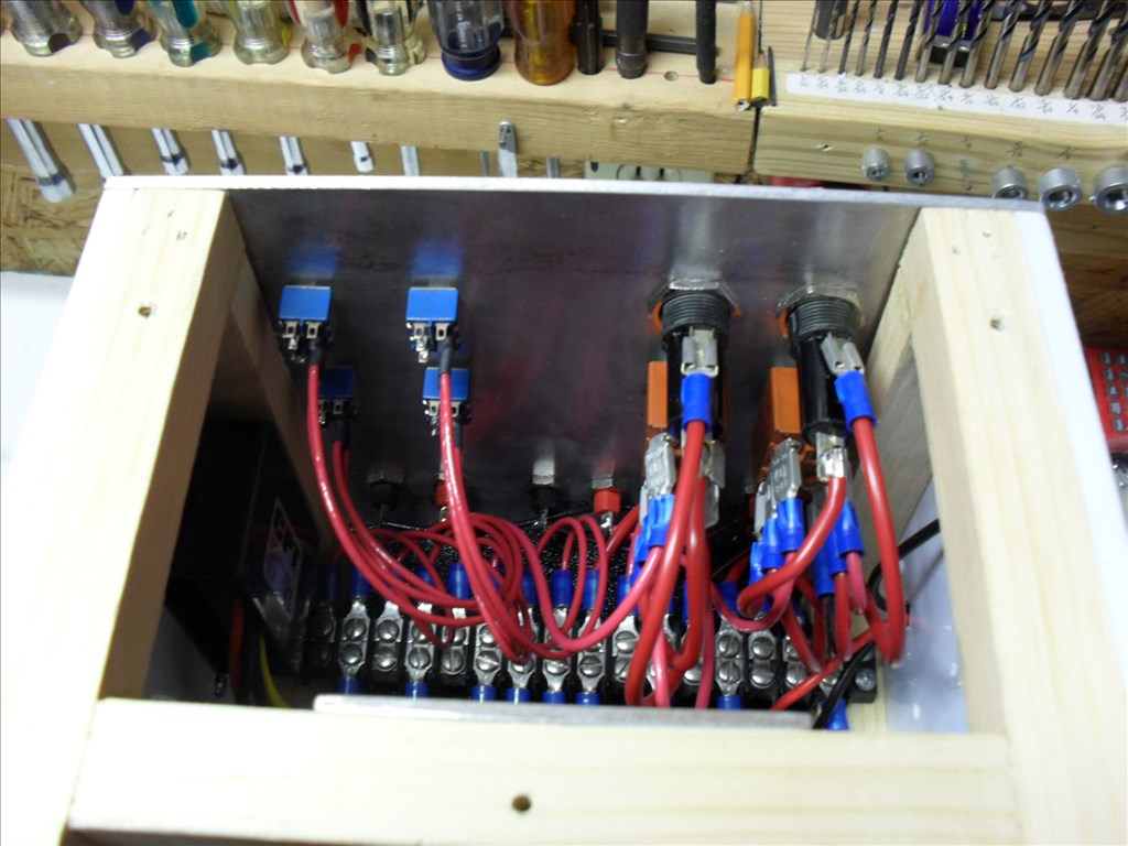
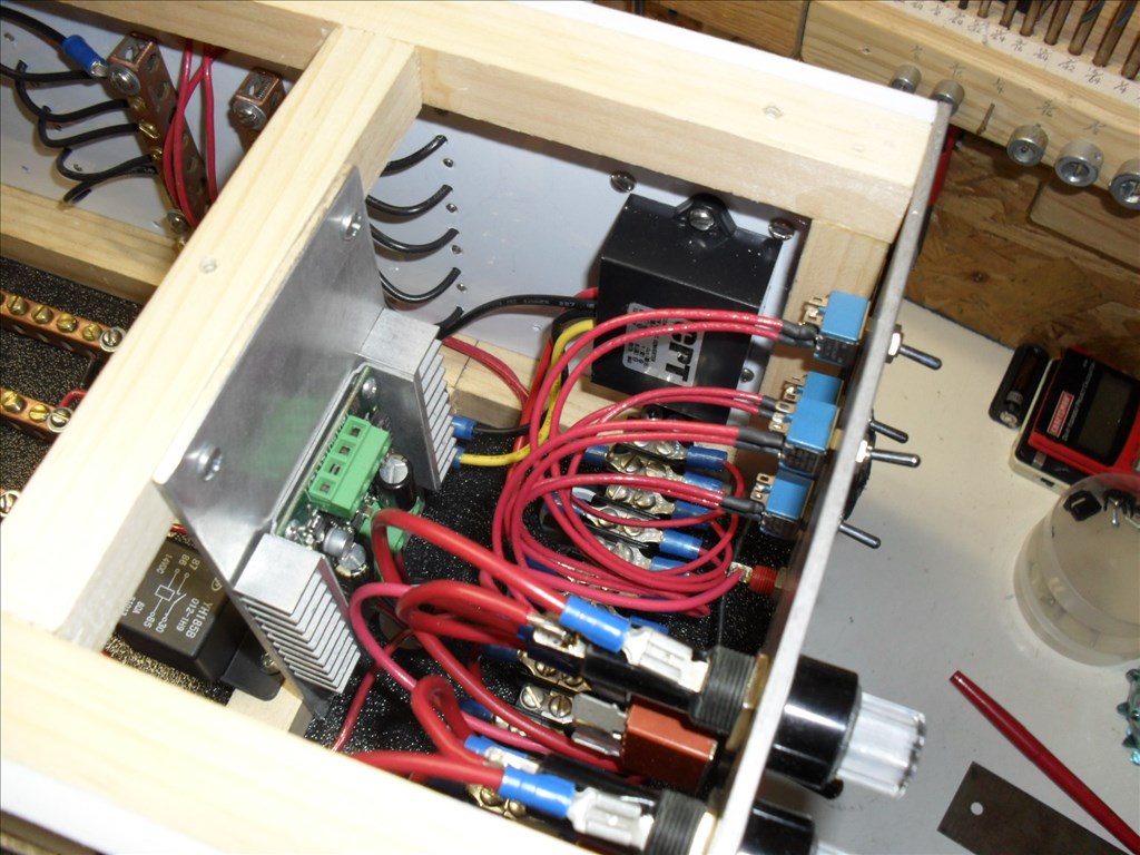
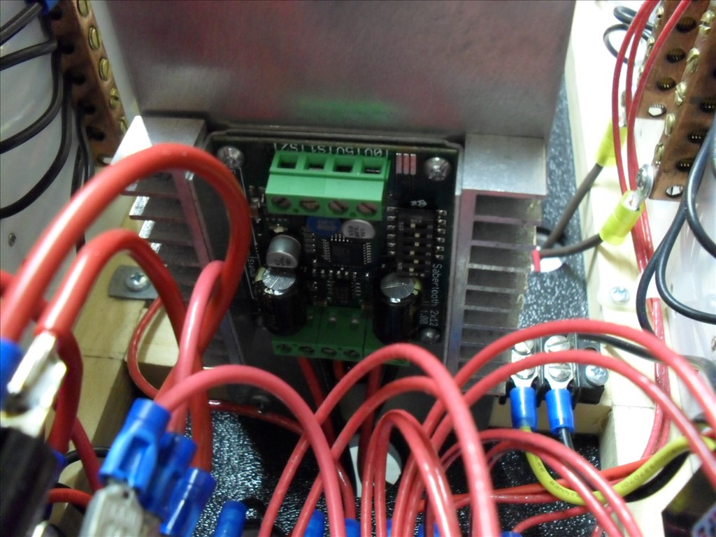
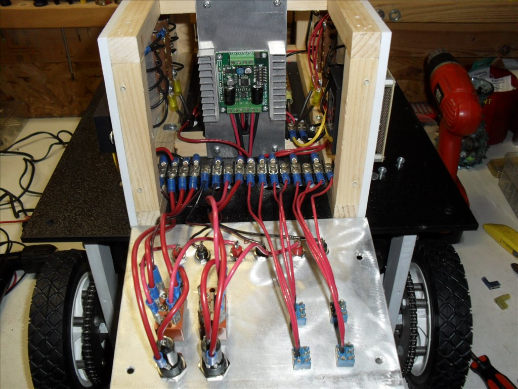

Weird....the pictures below [b]this line were not intended to be here in this first post. When I made the new post below, it saved the pictures in this post also. When I tried to go back and edit them out of this first post they don't show up on the thread so I can delete them. They belong in the post below....see details for the new wheels in the later post.[/b]
Discover more robots
DJ's Robot Blinds Control
Xuven's Project Atlas 1.0

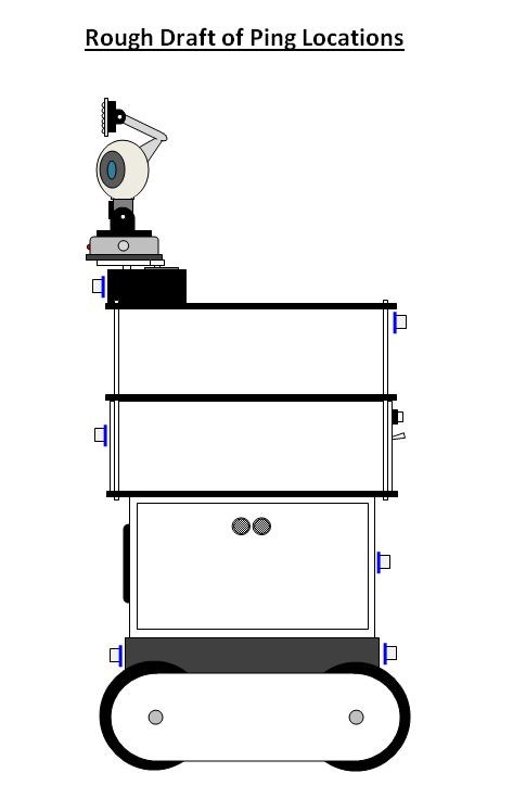
@rgordon, you may want to set up a battery monitor so that questor could tell you if his battery's low and later on make an ir beacon base for him to return to on low battery.
Questor Update:
Good news. Windows seems to be fine now considering the problem mentioned in the last few posts.
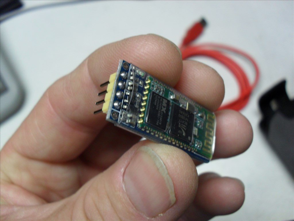
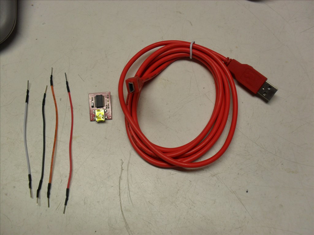
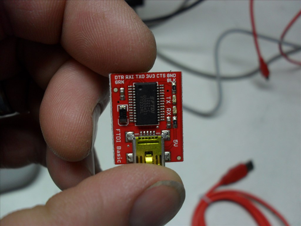
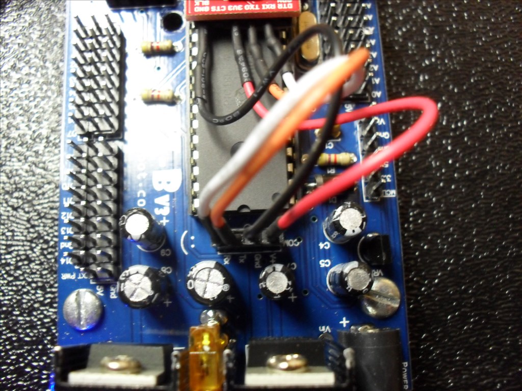
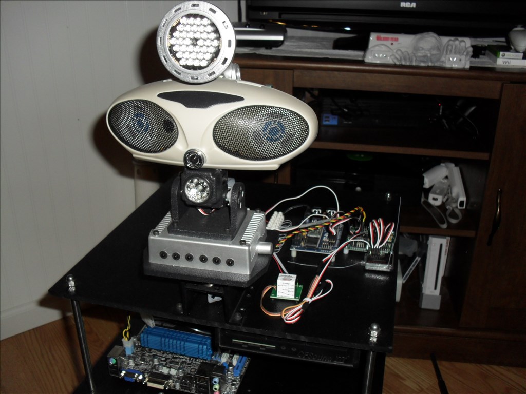
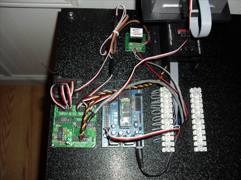
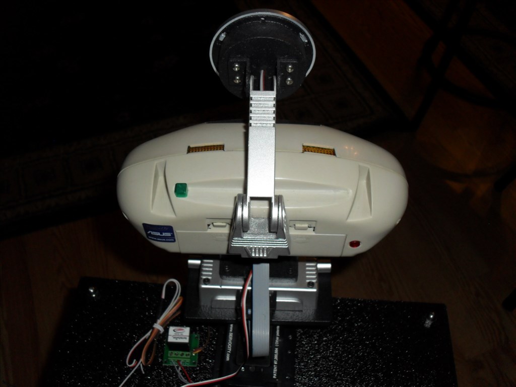
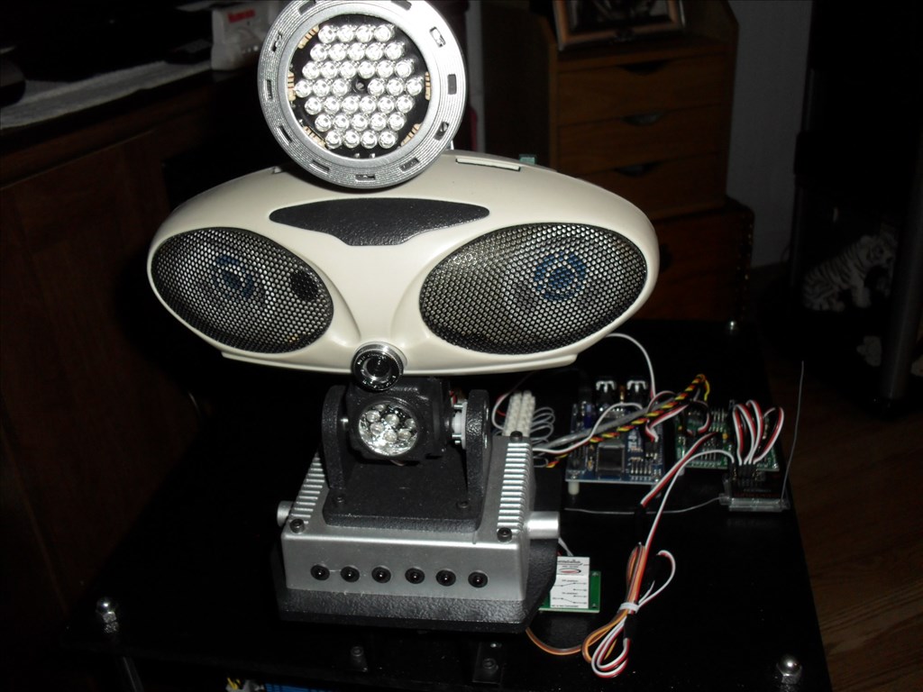
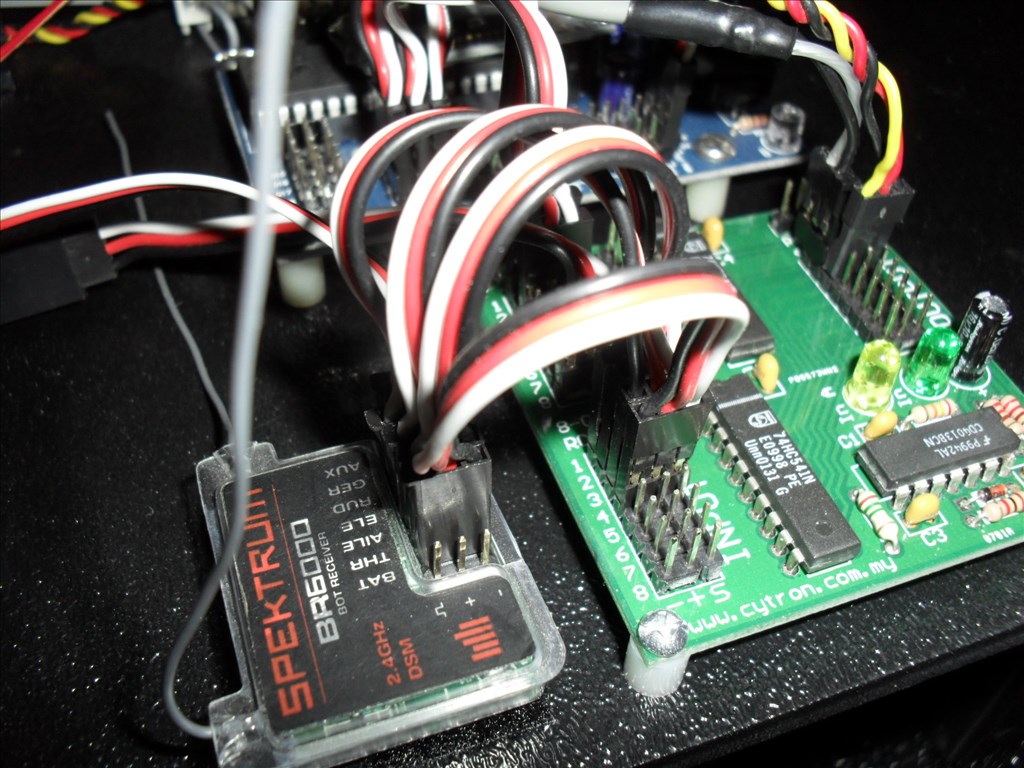
Also, I decided to use the new EZ-B I just got to test the SparkFun FTDI (USB to TTL) Adapter in place of the Bluetooth module that sits on top of the EZ-B. I was eventually successful. Here are the steps I went through:
I very carefully removed the Bluetooth module from the EZ-B by using a small flat blade screw driver to pry it up.
The double sided tape eventually let loose from the IC Chip and I pulled the module free from the EZ-B header .
I used the male jumpers that I got from the EZ Robot Store to hook up the FTDI header to the EZ-B header. VCC to VCC <- EDIT: Found out this connection is not needed. GND to GND Tx to Tx Rx to Rx (Yes that's right Tx to Tx and Rx to Rx. I thought it should be Tx to Rx and Rx to Tx but that did not work.)
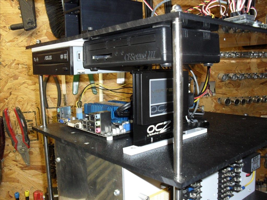
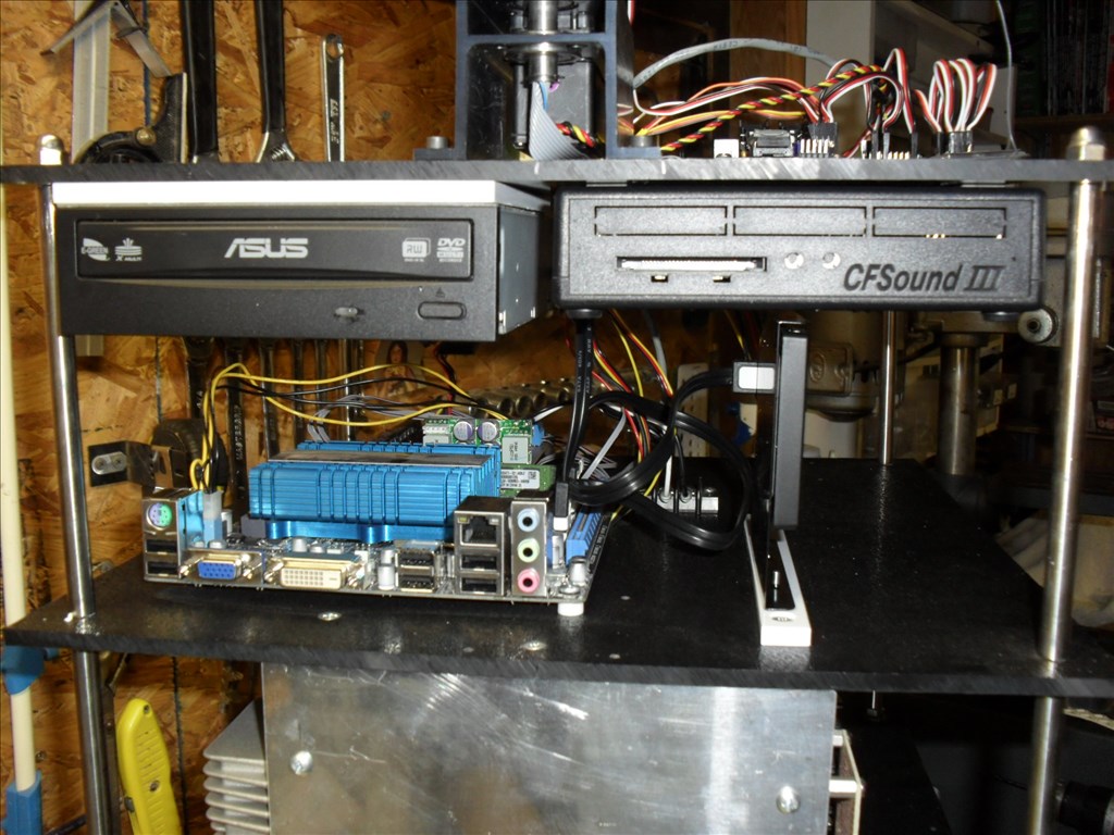
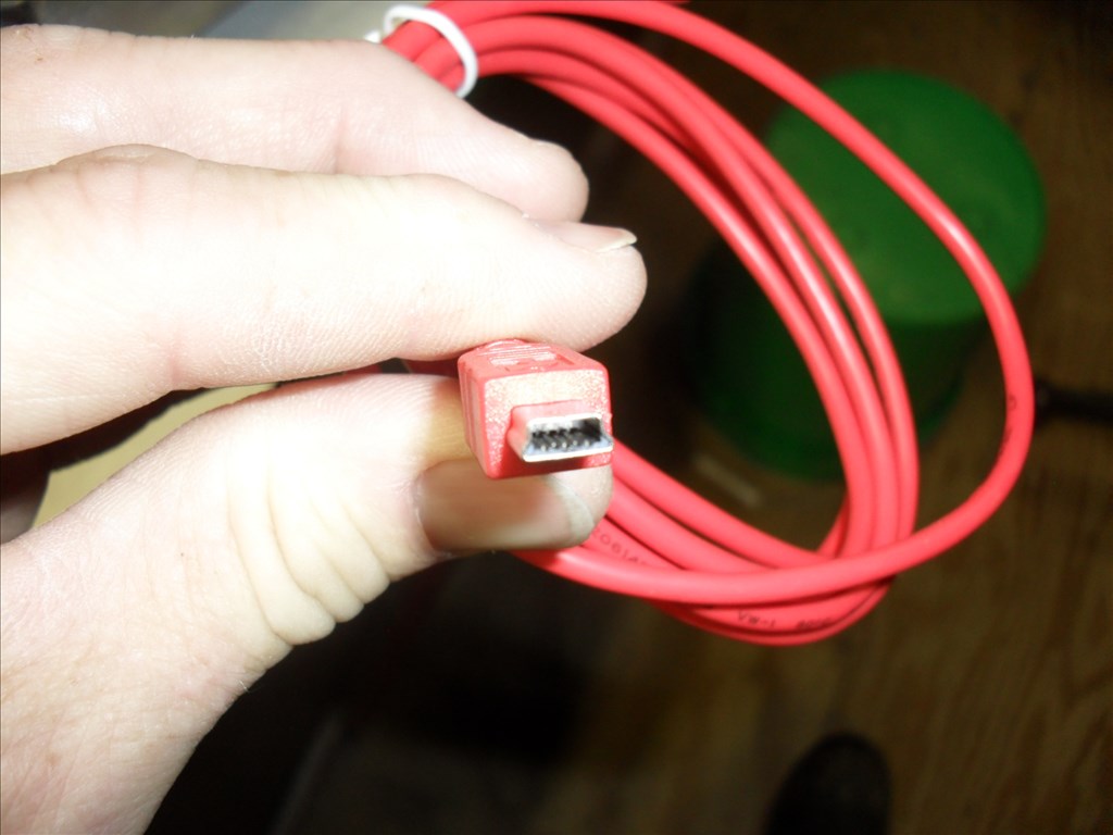
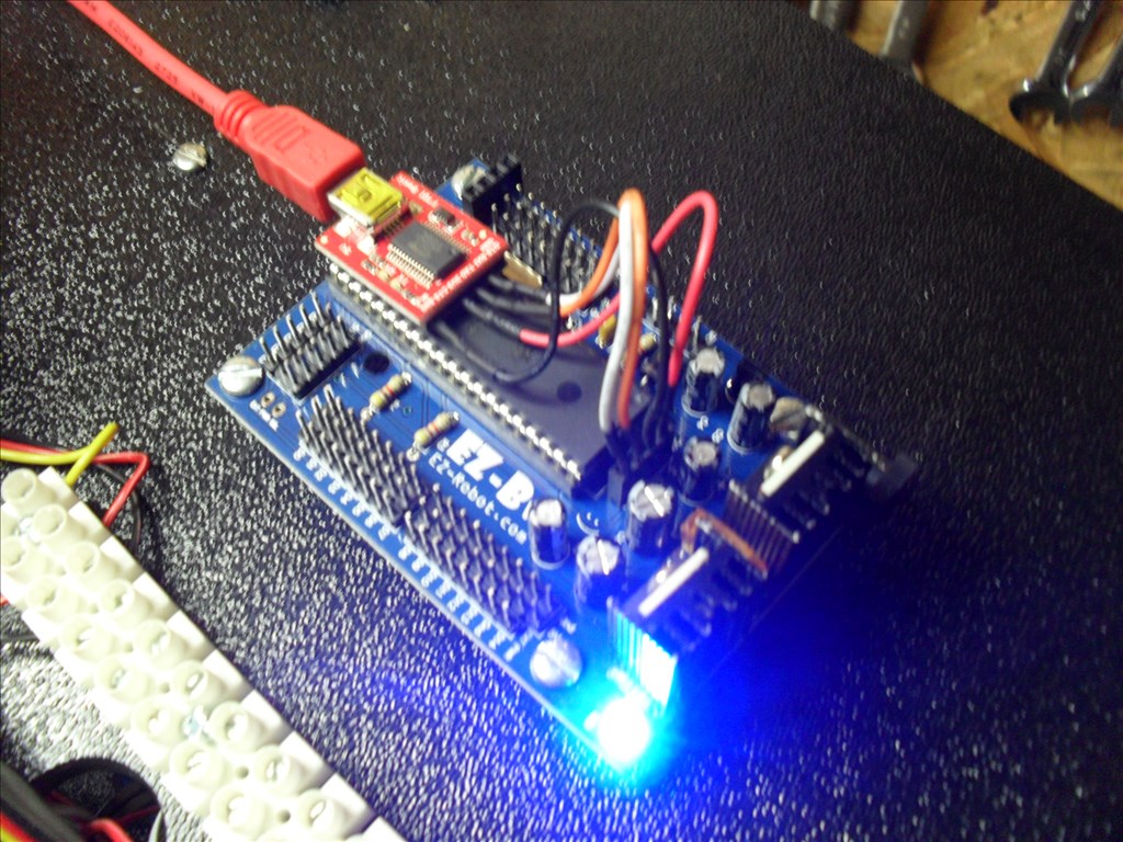
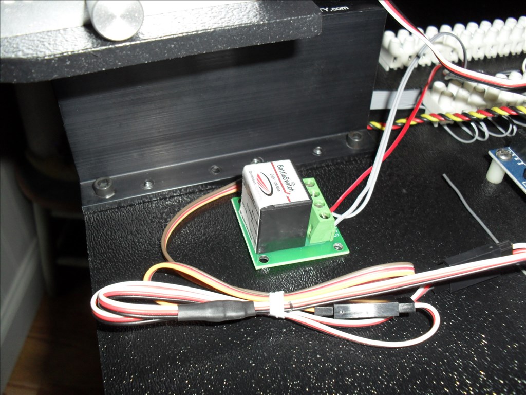
I hooked the SparkFun Mini-B cable from the FTDI board to the ASUS Mini ITX motherboard.
I powered up the EZ-B using a battery pack and then powered up the ASUS Mini ITX motherboard.
Windows 7 Home Edition (64 Bit) informed me that it could not find a driver so I let it search the internet.
It eventually found, loaded and installed a "FT232 USB UART" diver and assigned it to COM 7.
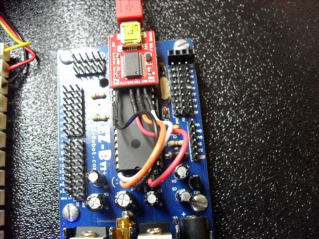
I started ARC, chose COM 7 and clicked on Connect. The EZ-B blue LED went from blinking to solid blue and all looked good. I hooked a servo to D0 and tested its operation with good results.
Notice anything interesting in the picture above?..... When I unhooked the battery pack from the EZ-B the EZ-B remained on. It was being powered from the Mini ITX. Connection was not lost. The blue LED remained on. However, I found that the servo would not work anymore until I hooked the EZ-B battery pack back up. EDIT: Found out the VCC to VCC connection is not needed.
Note: I posted this as a Tutorial under the Hardware Tab for others who might find it useful so they would not have to find it buried here under this topic.
Awesome tutorial! I had a bit of advice that I shared in the other thread.
Great work rgordon! I will order one of these when I decide to embed a board.
Questor looks cool. Hope you and your robot building buddy get time to work on Questor.
@mcsdaver Thanks. I thought Questor 1.0 turned out pretty good. It helped me answer a lot of questions before I move on to the next phase...........Questor 2.0. Which has its good and bad properties. Being that parts, servos, sensors, etc. cost so much and there is no room in our house for two robots, I have taken Questor apart. He will be reborn into Questor 2.0 a larger version. I am in the preliminary stages of doing this and will create a build thread soon.
Happy Building!