


Now I have the EZ-B kit and the Hearoid it's time to start my Showcase thread.
I still haven't decided on a name for him yet, all suggestions are welcome.
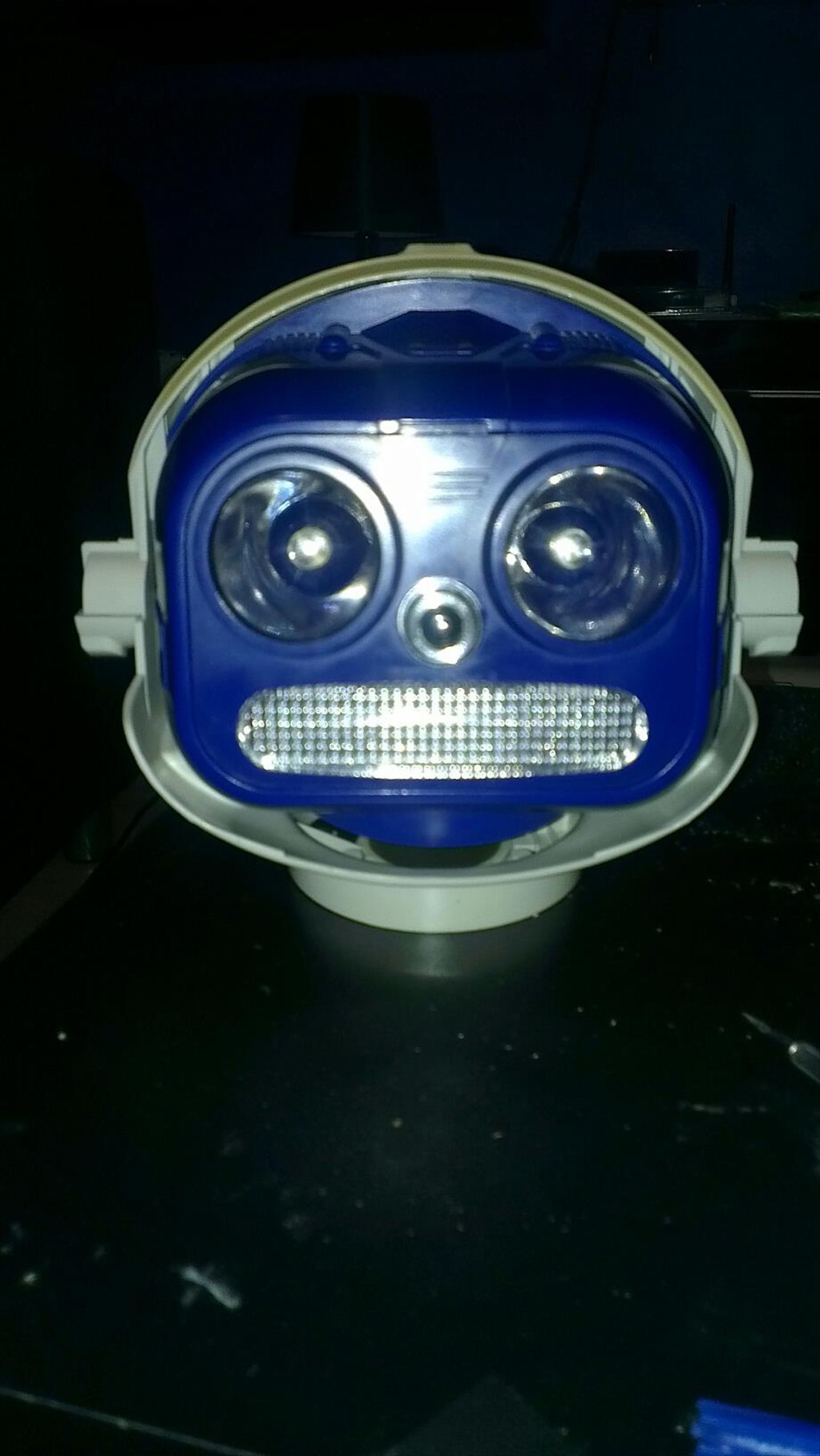
I won this robot on ebay weeks ago, for the past 2 weeks he has been waiting for me to collect him...
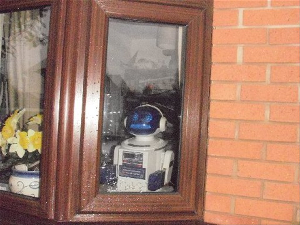
Today was the day, a road trip to pick him up and bring him back to his new home...
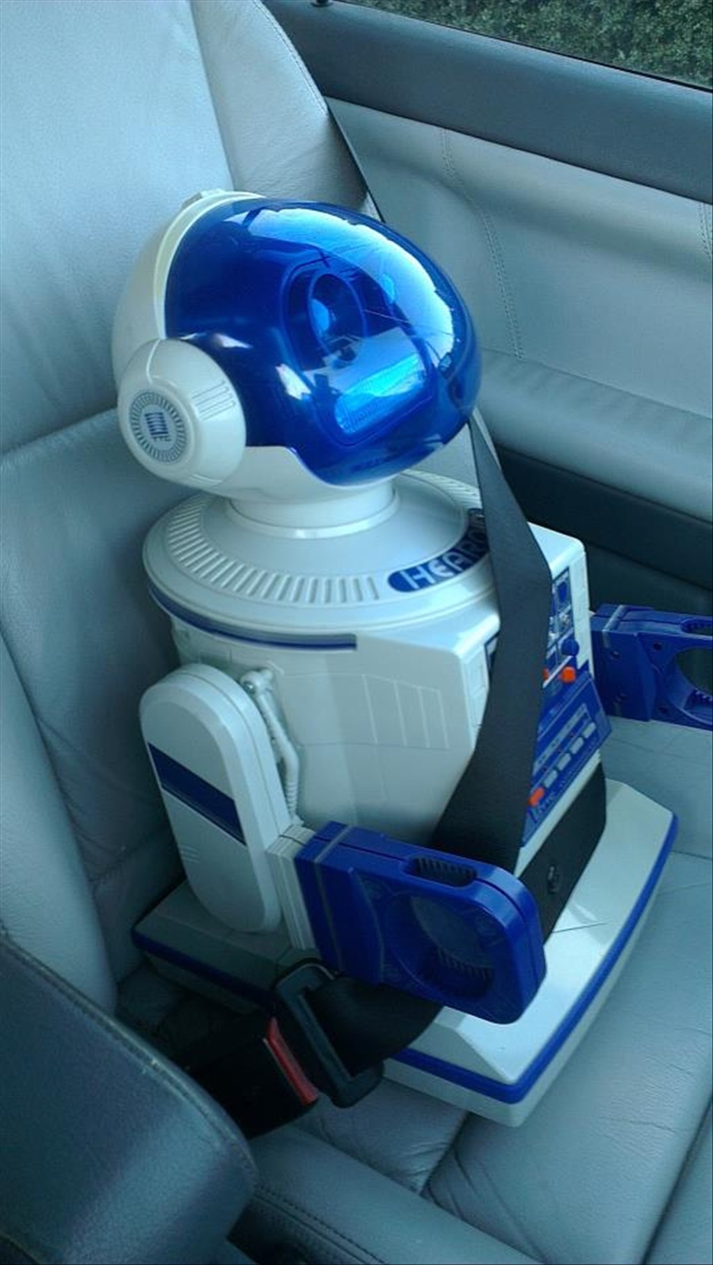
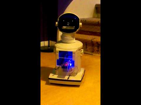
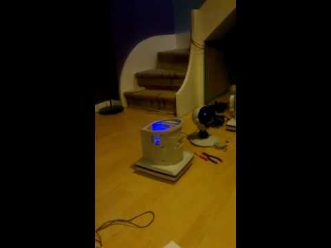
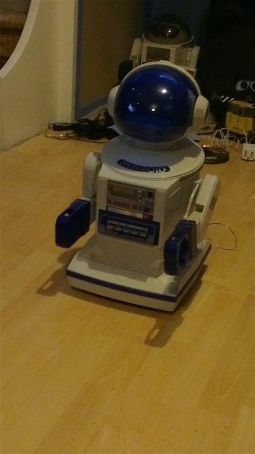
In his new home (with Omnibot and Wall-e in the background totally unaware they are next in line to be opened up)
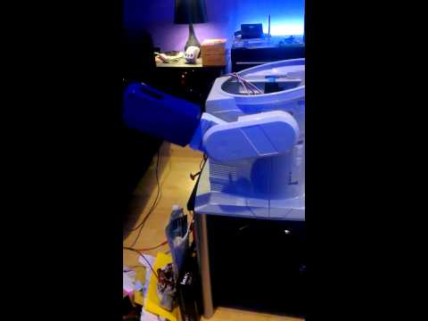
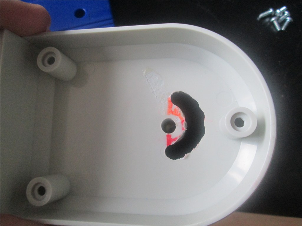
It wasn't long before this happened...
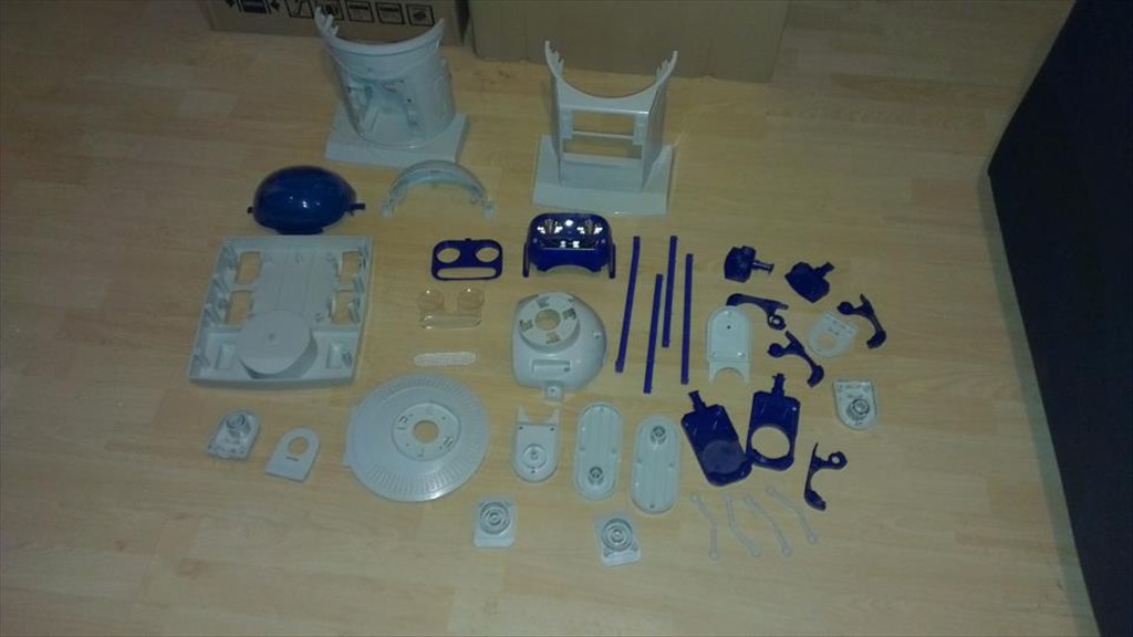
Now waiting to go in the dishwasher to get nice and clean.
The plan is to make him autonomous, running 24/7 (except for when he knows to go charge himself up) but will also be adding in the various image tracking options.
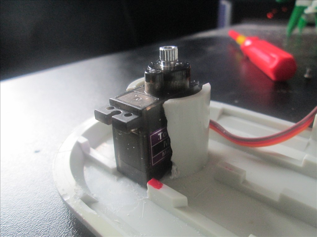
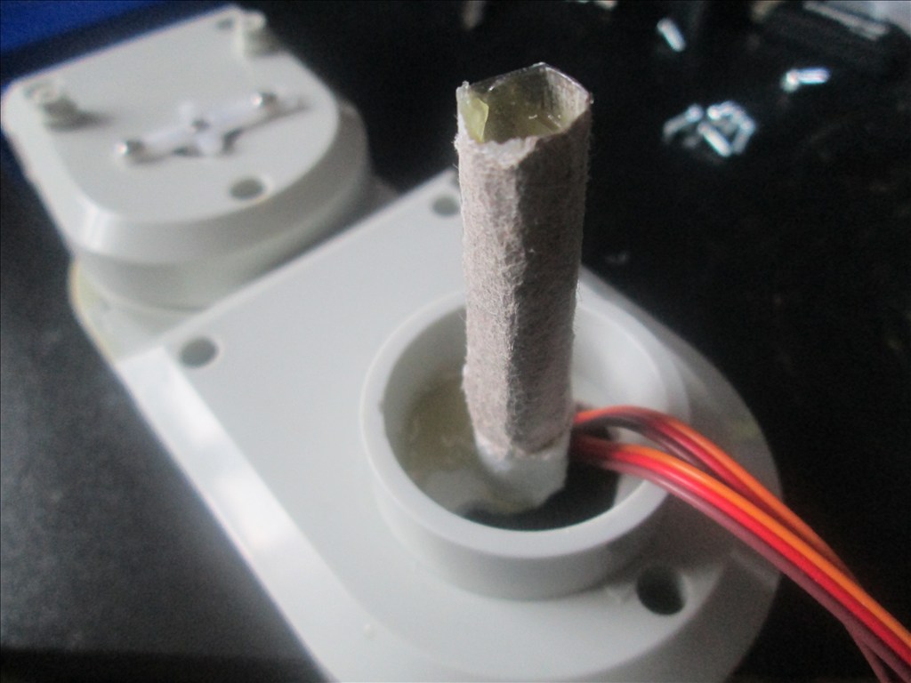
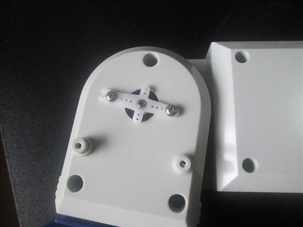
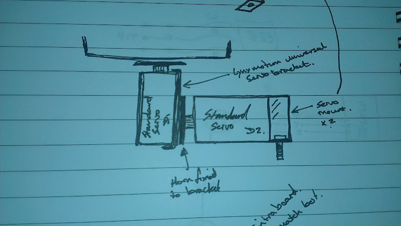
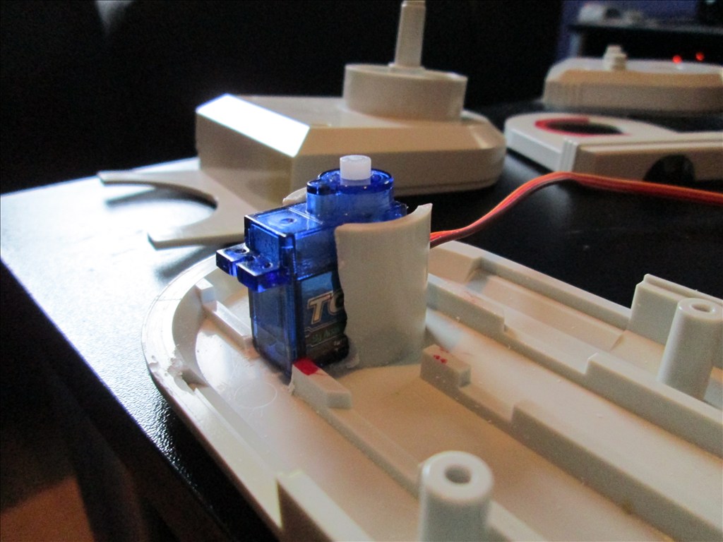
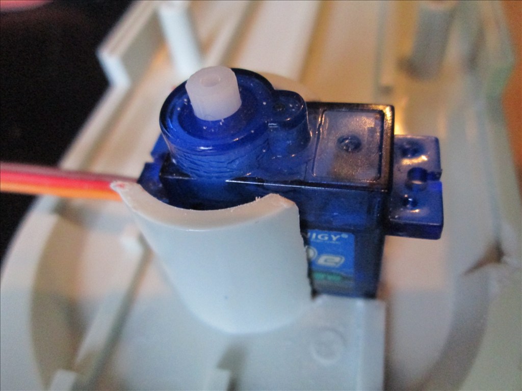
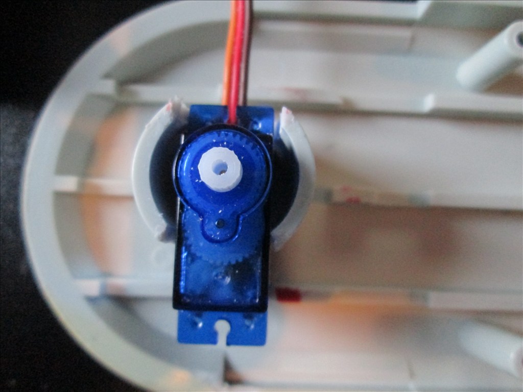
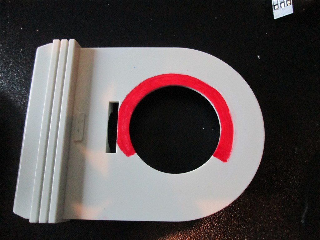
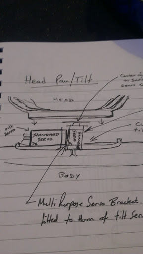
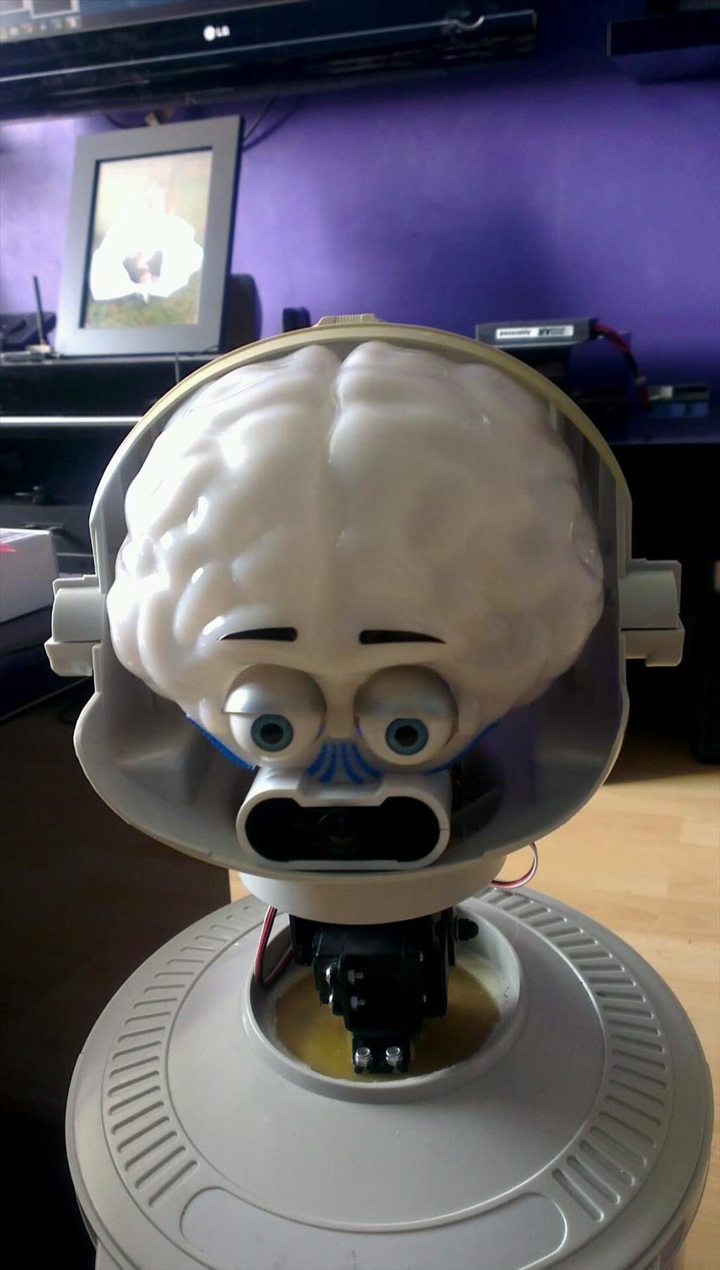
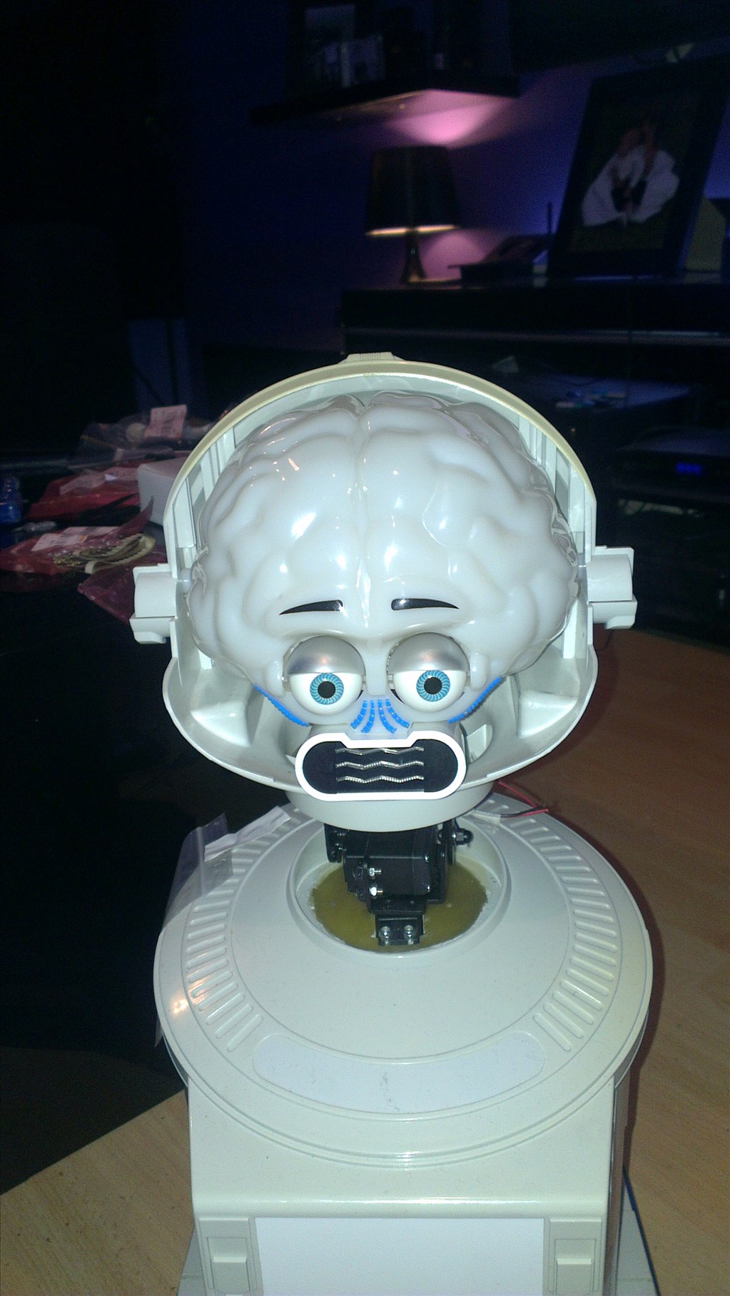
The only other slight modifications to be made to him are to convert the head to tilt & pan which will involve having to give him a small neck.
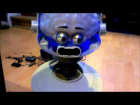
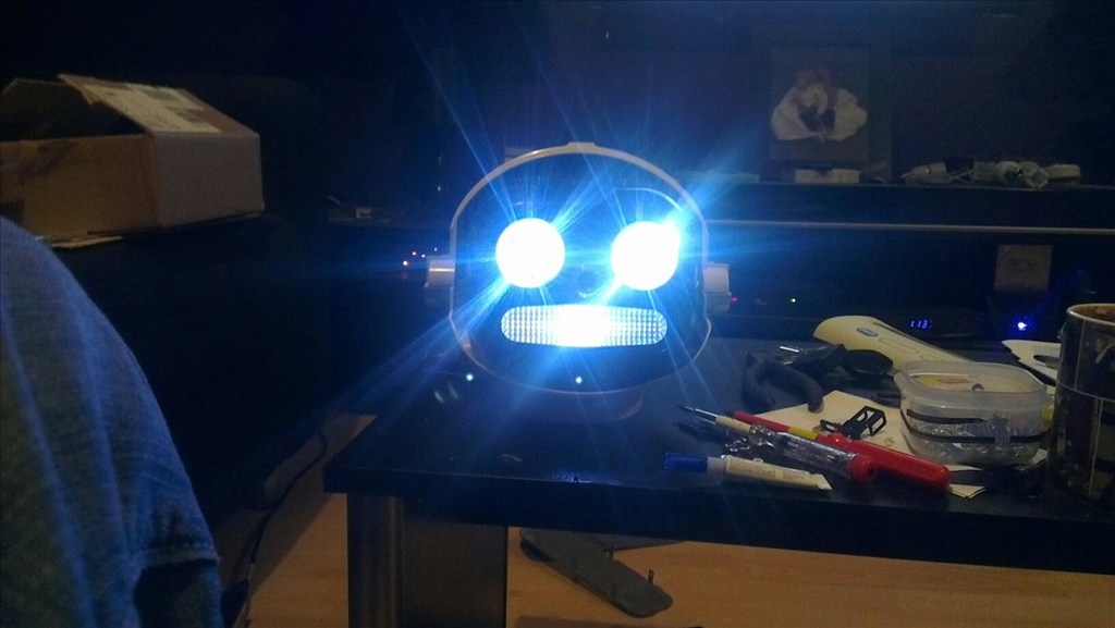
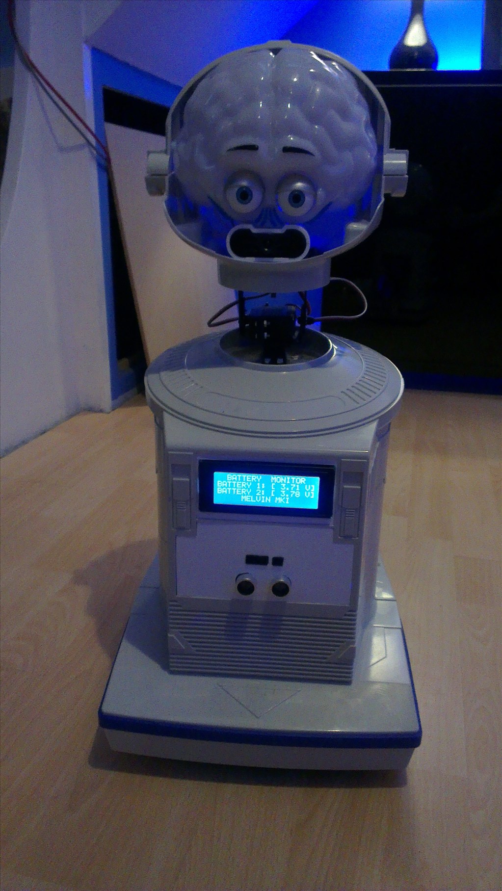
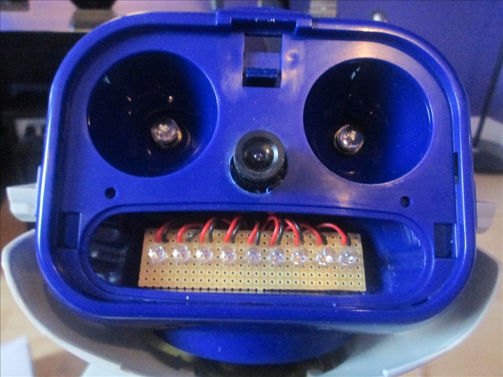
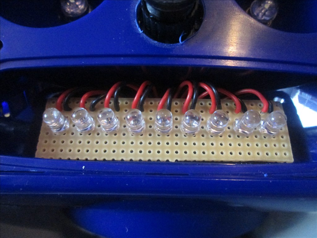
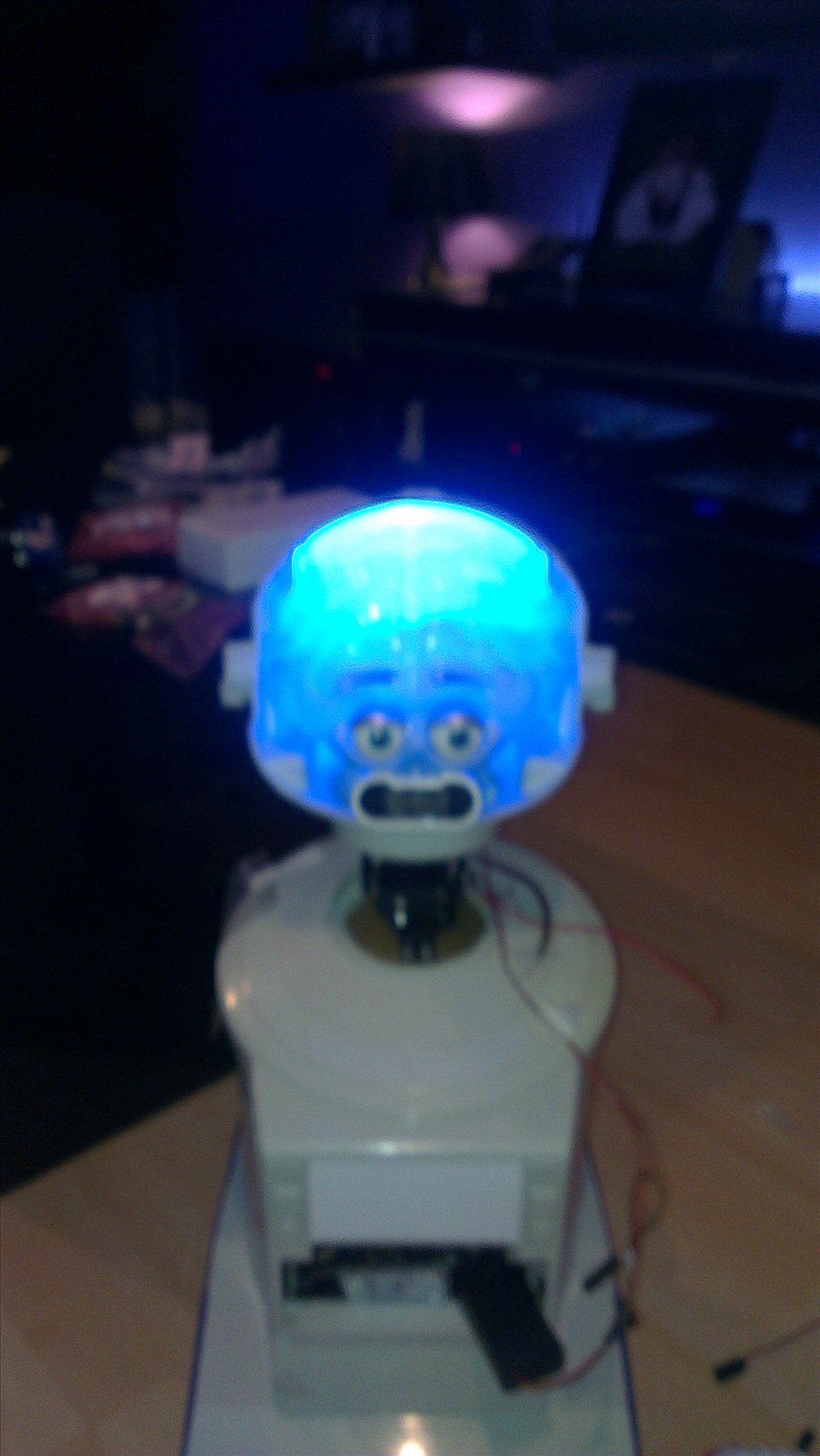
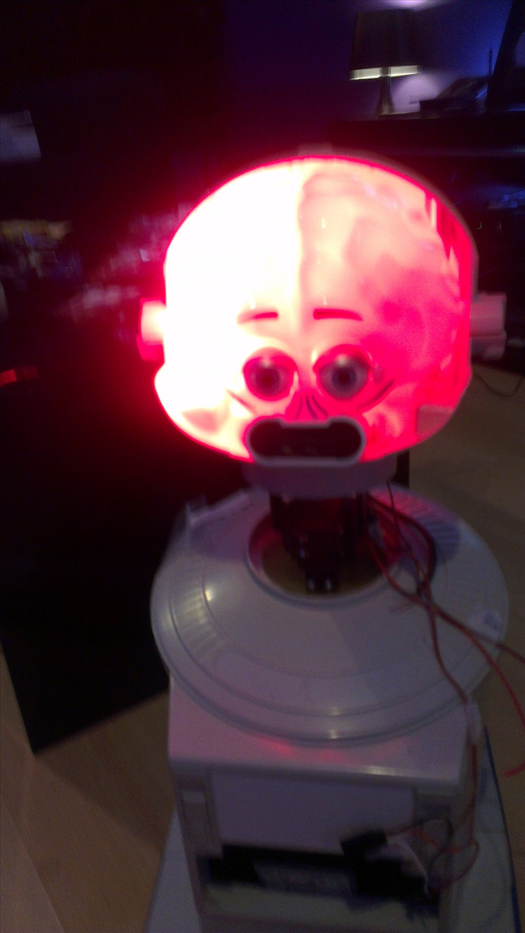
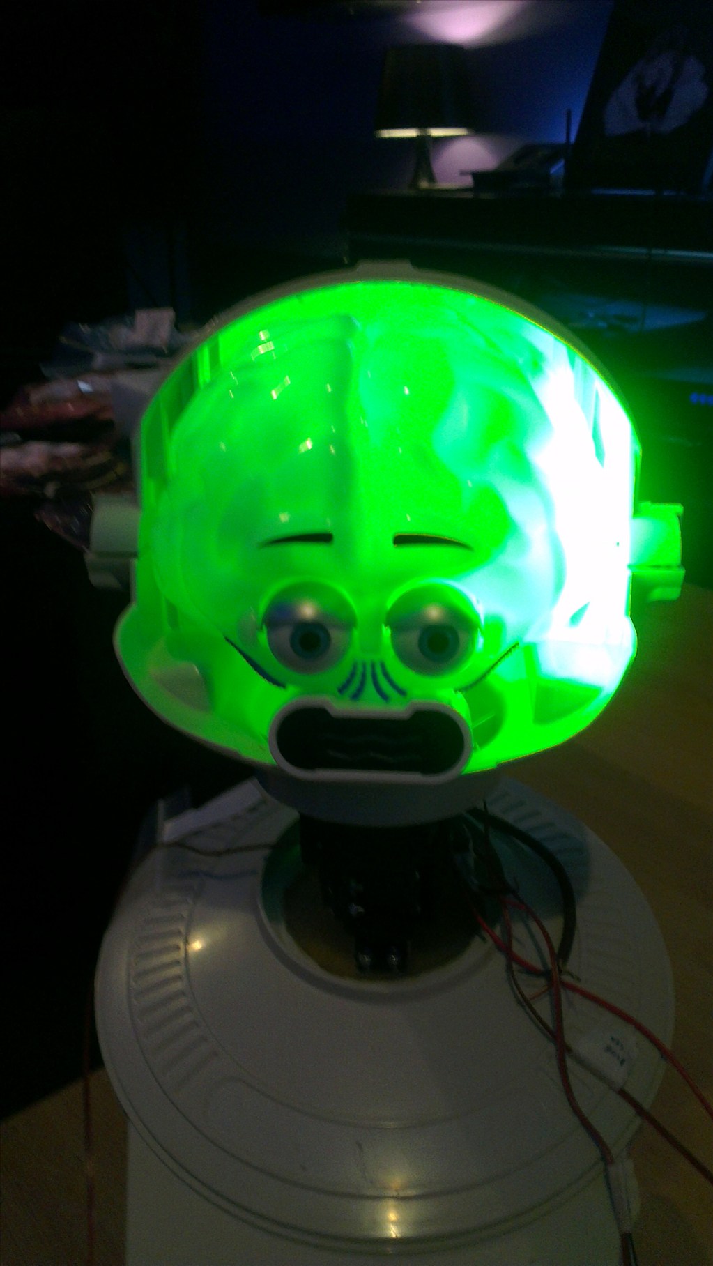
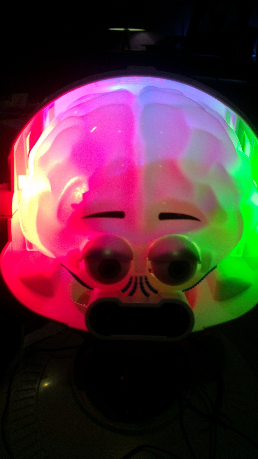
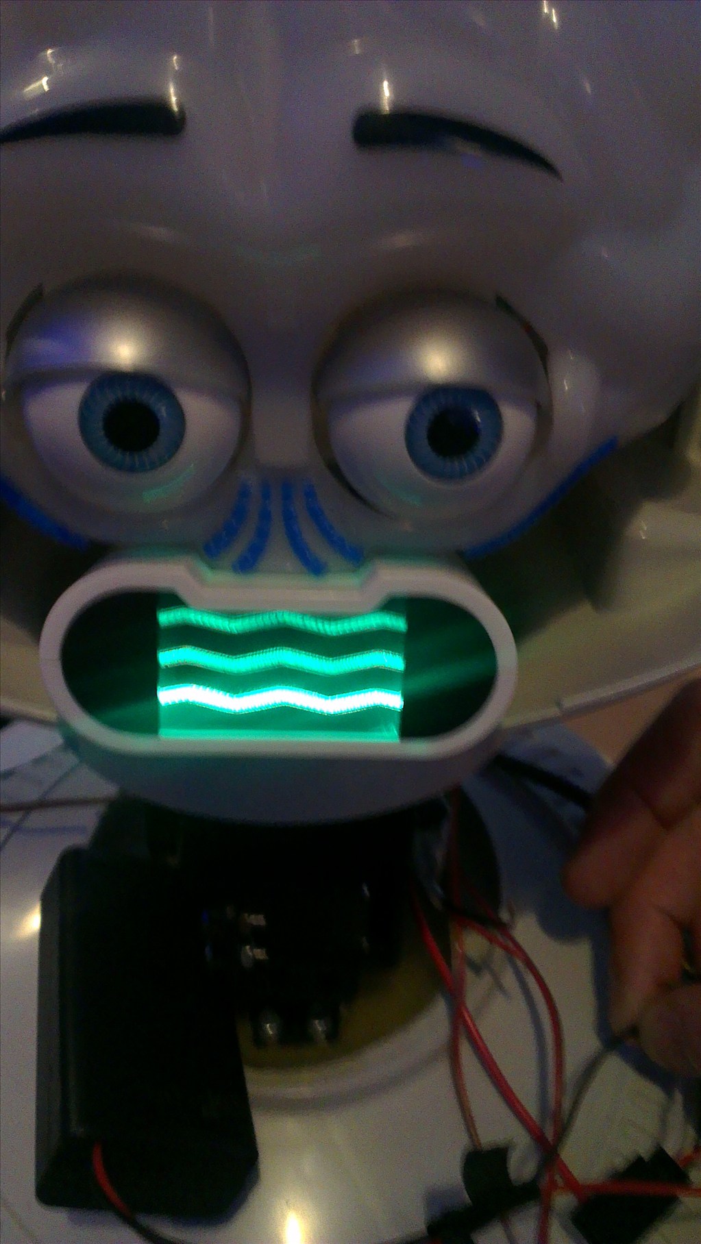
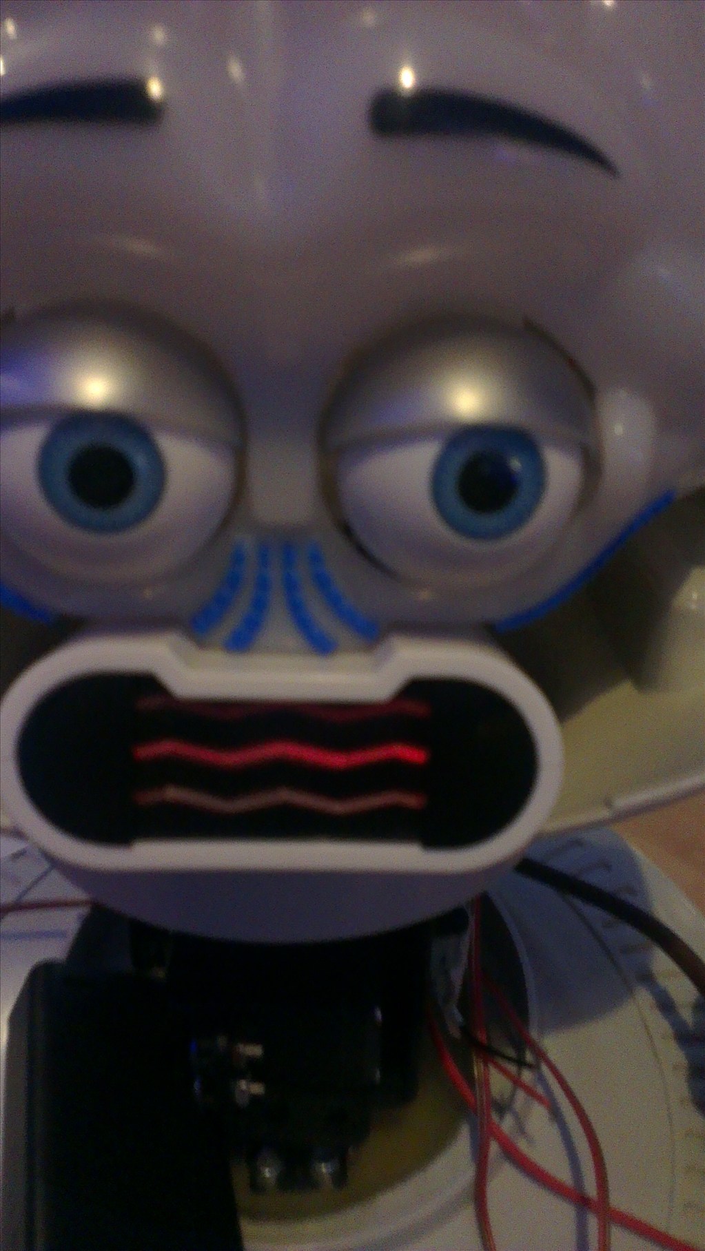
The head will include the camera. I haven't yet decided to fit it in one of his eyes or to make it his nose. The issue to overcome with this is the blue tint on the bubble head. The mouth will have a light or some lights in which flicker when he speaks.
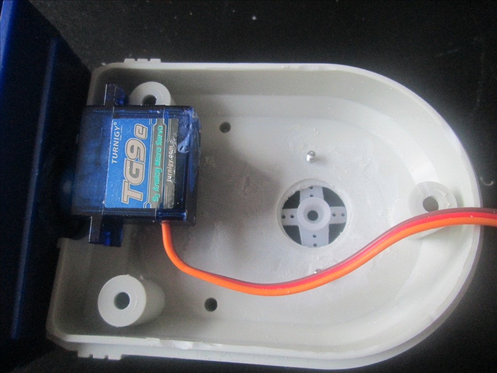
The arms will be given some life with servos at the shoulder joints and the elbows provided I can get them to fit in there nicely.
Ultrasonic sensor will be in his chest, probably on a servo to give a wider view.
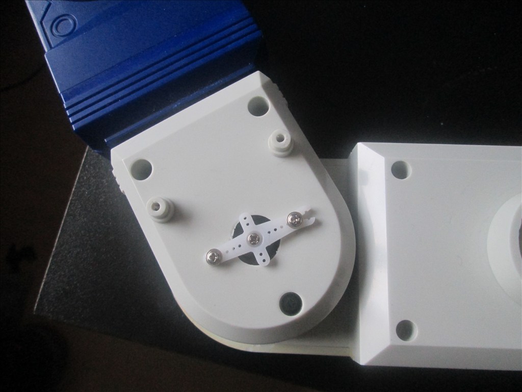
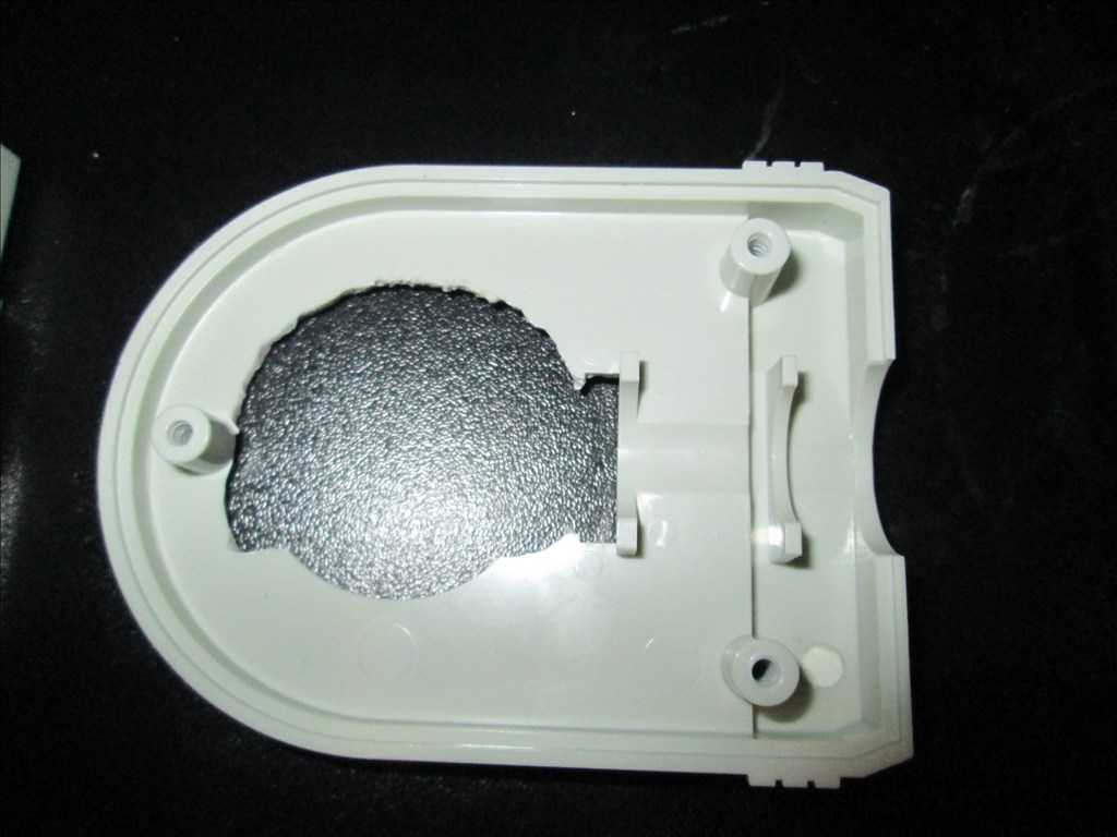
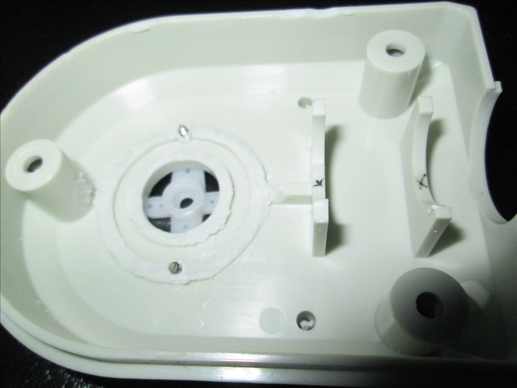
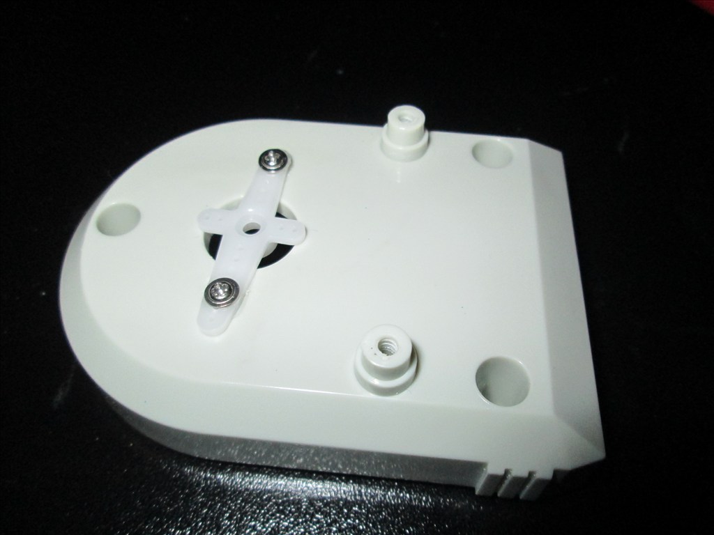
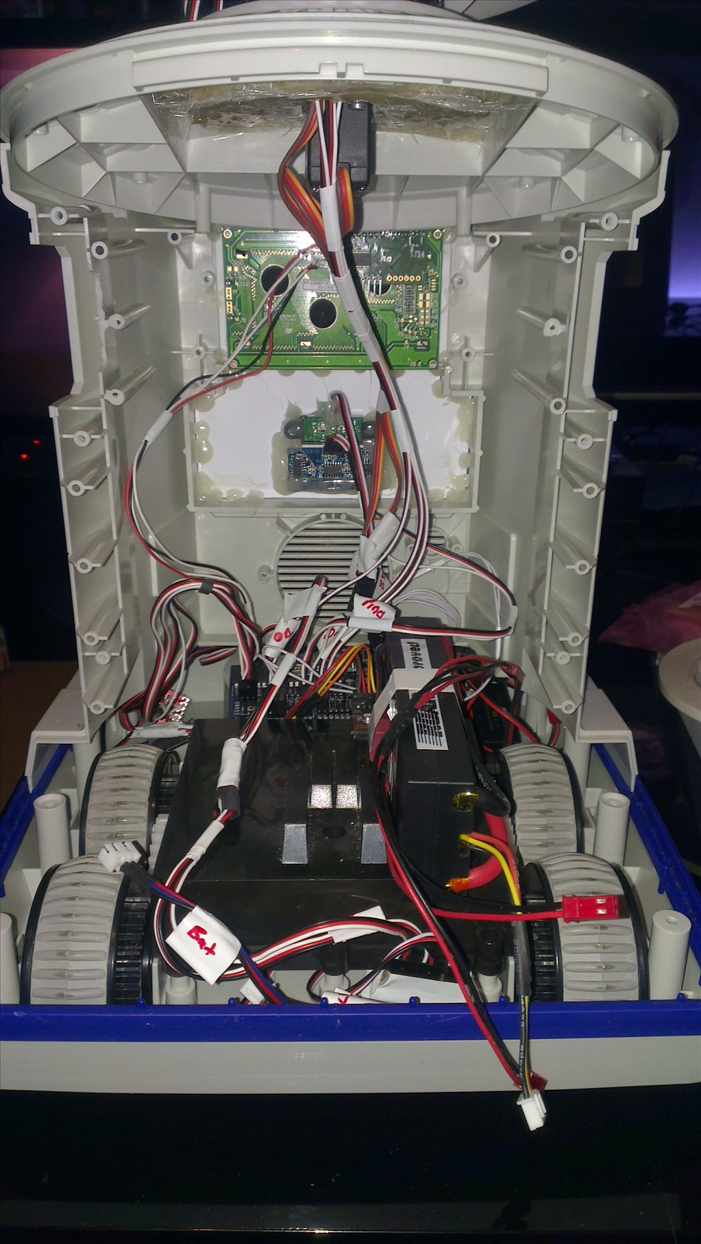
Original drive wheels and gearbox seem to be in very good shape so will plan to reuse those and just replace the existing motors for the modified servos if they can manage the task.
Speaker and microphone will be in the original positions - if it's not broke why fix it?
Not too big a project but enough to give me a test, help me learn and bring an old robot back to life.
Discover more robots
Rb550f's Ez Robot Attacknid
Ezang's RGB Arduino, Python Code With ARC

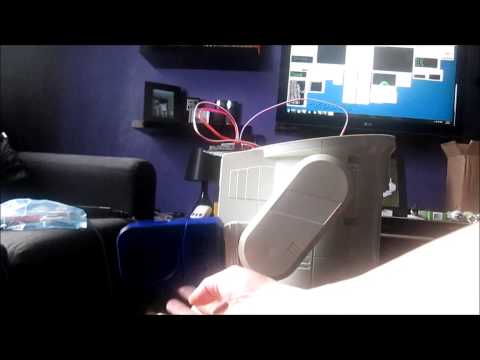
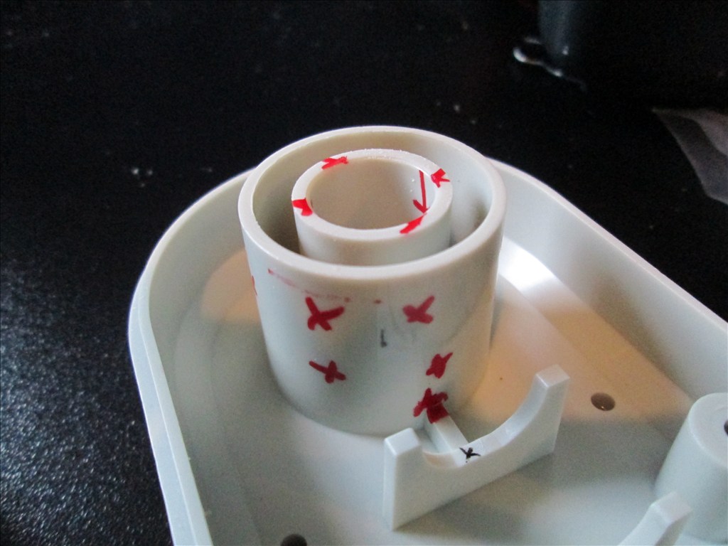
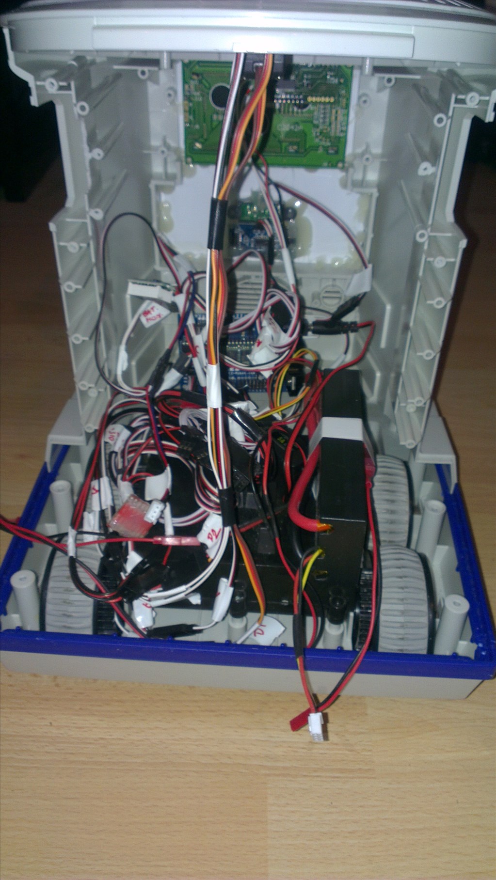
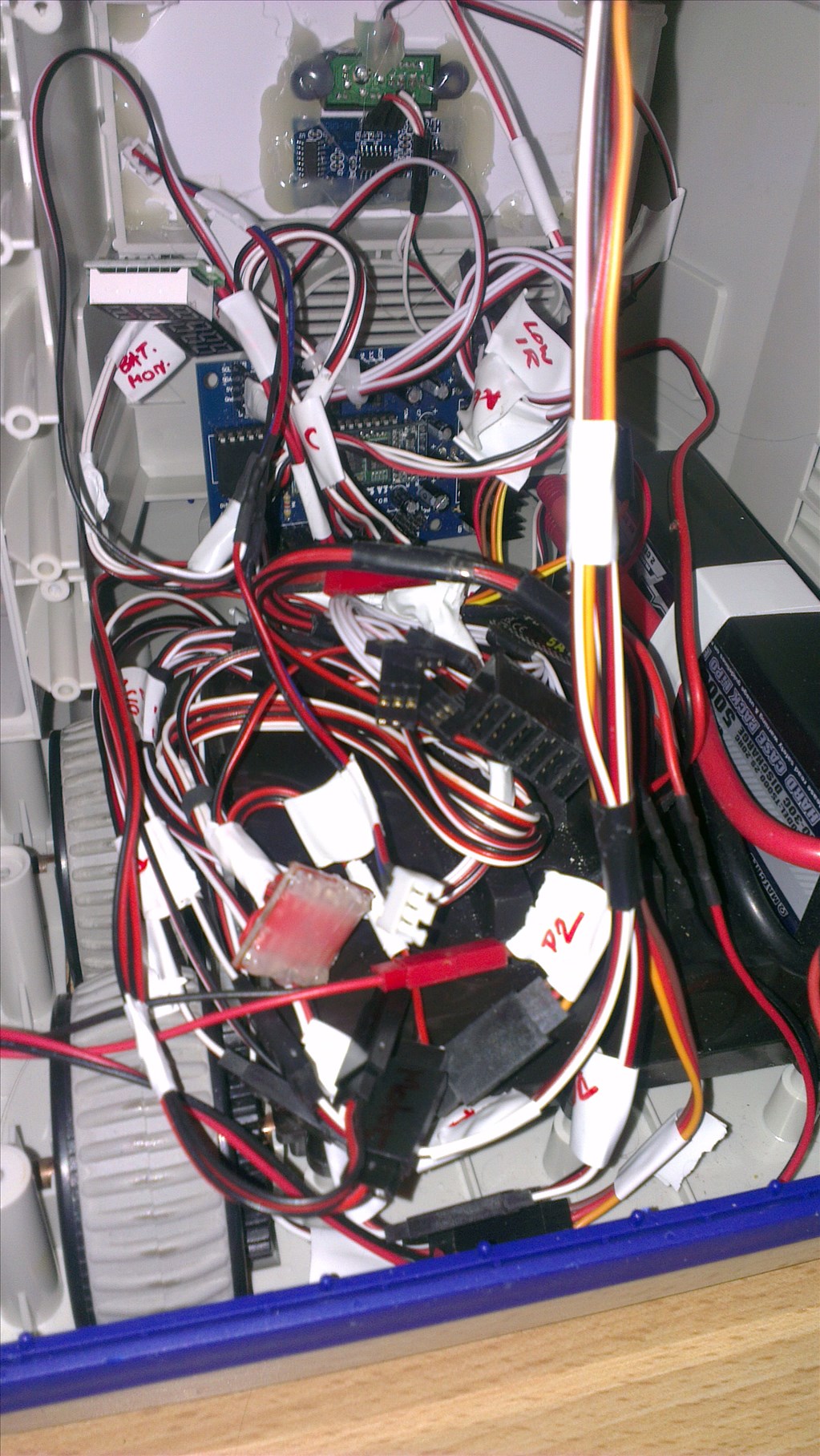
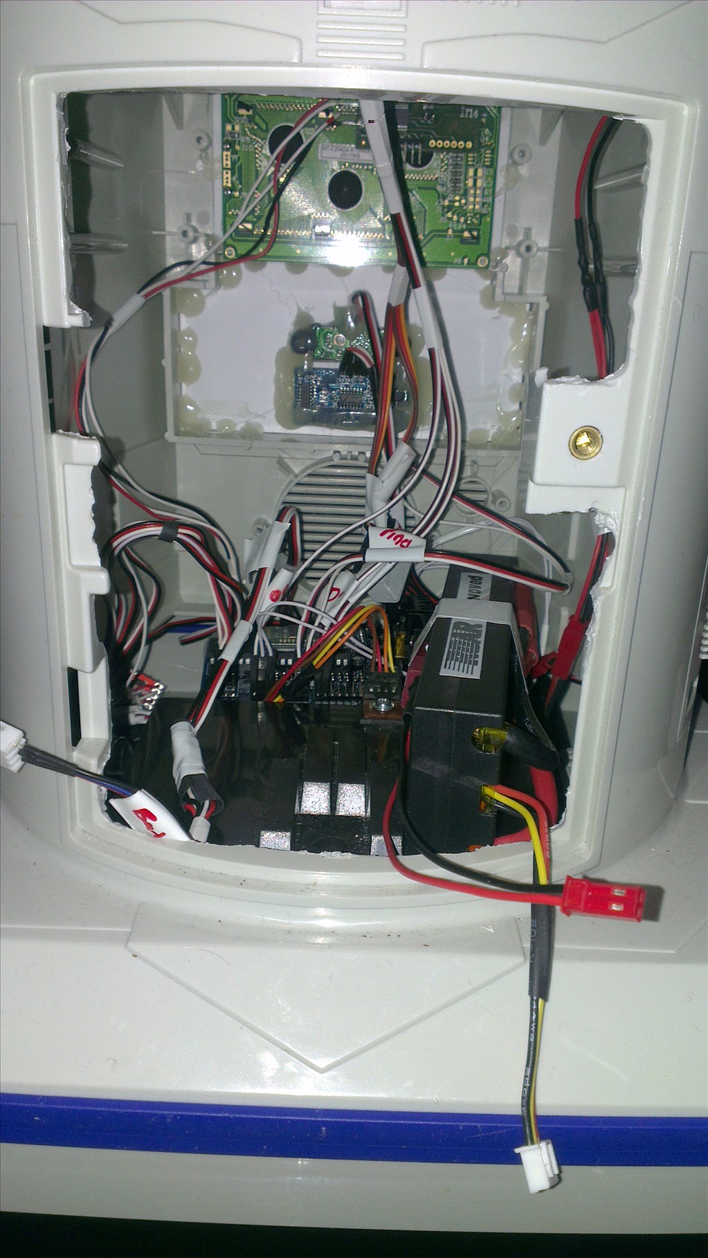
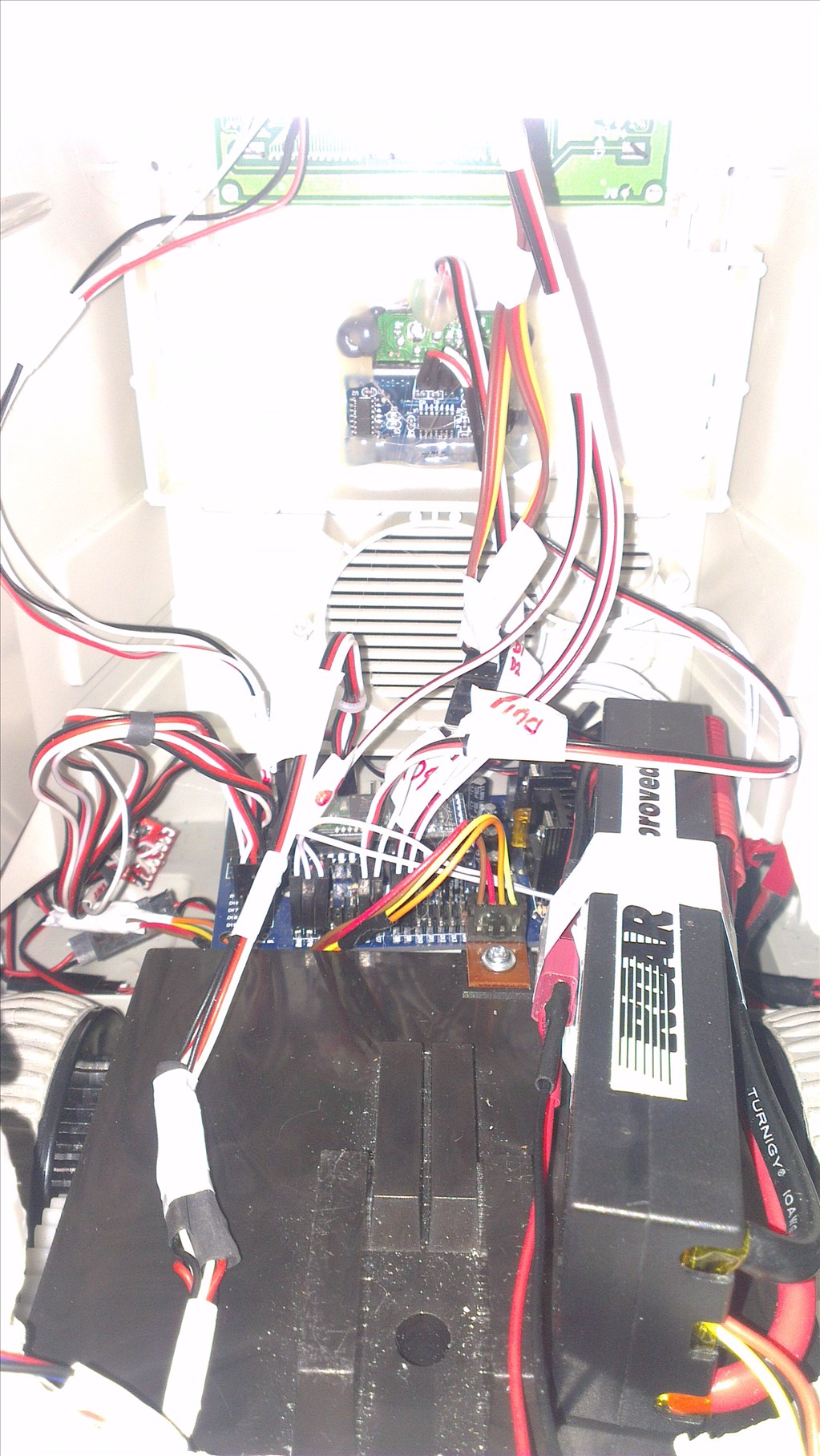
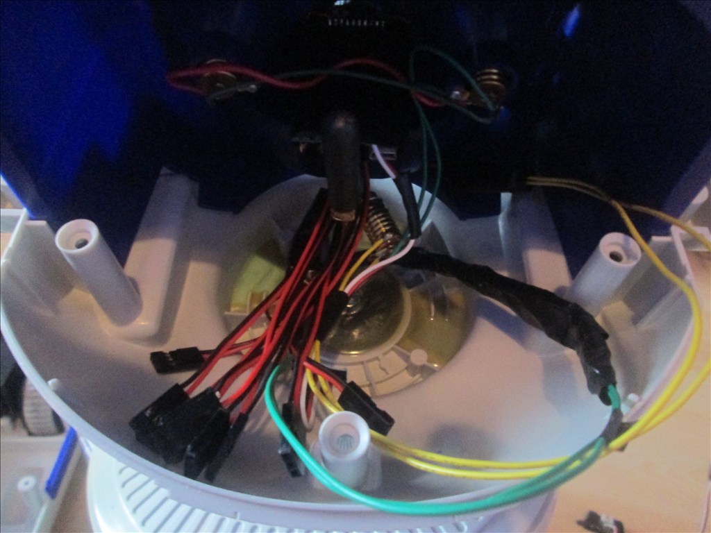
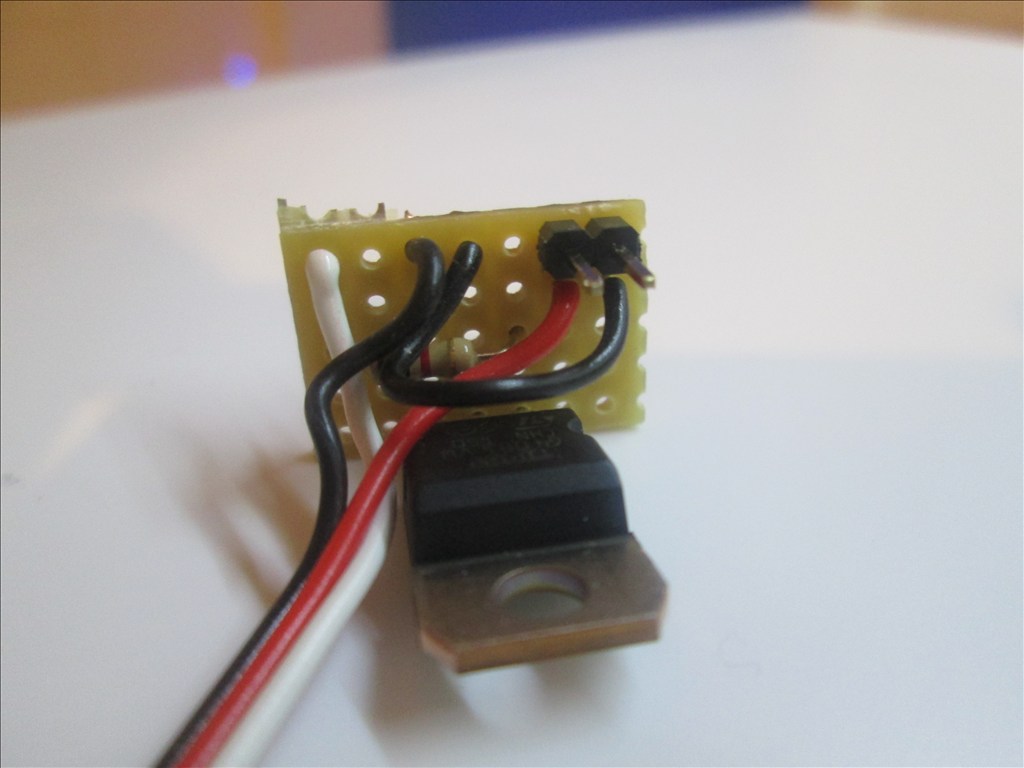
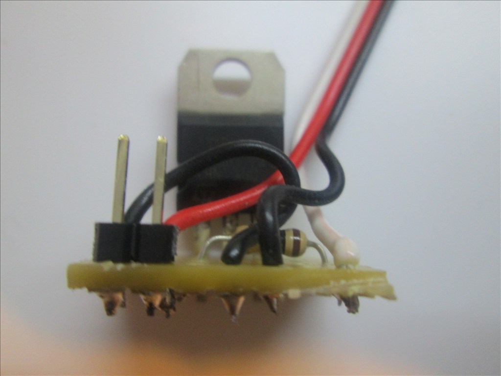
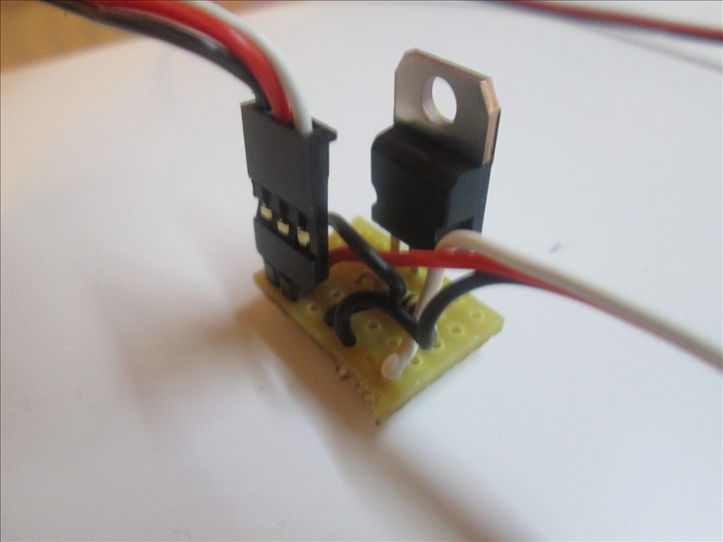
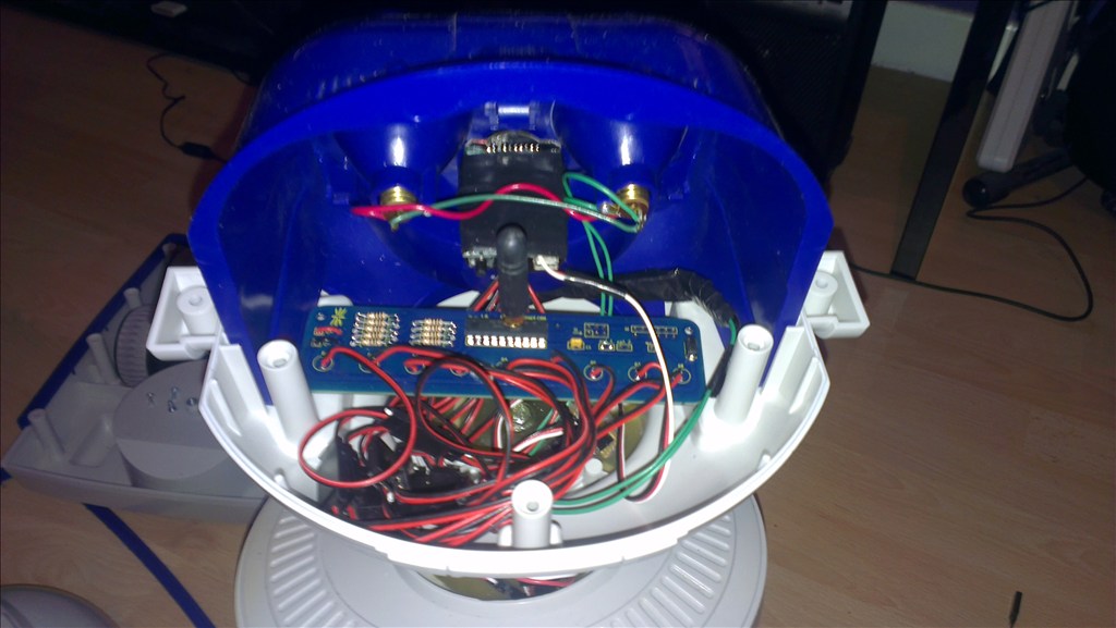
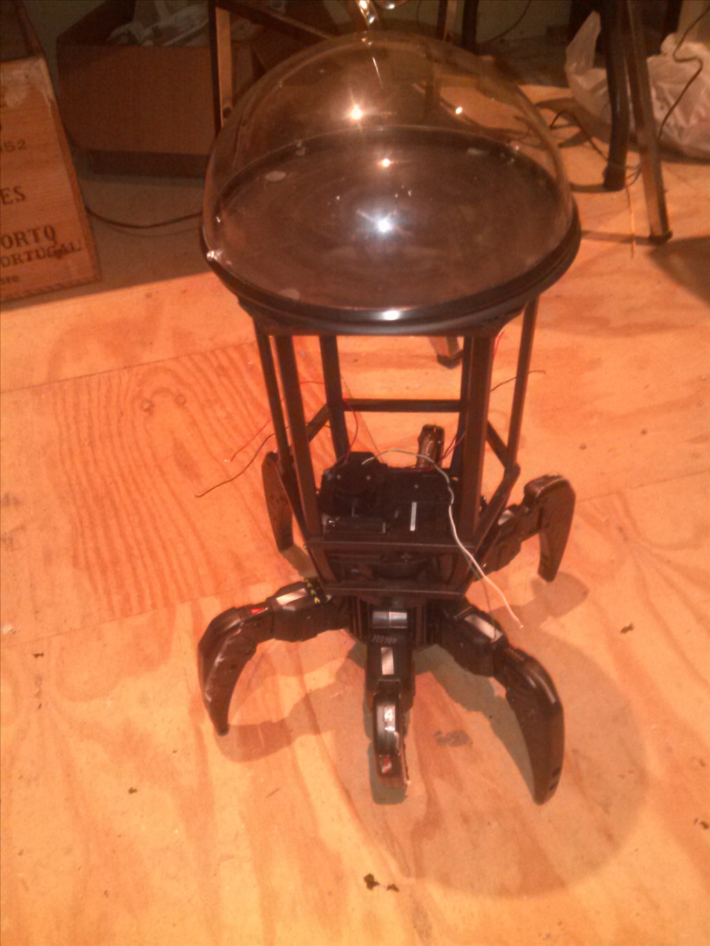
While I had the back off I thought I would take a couple of photos...
A huge mass of wiring to be tidied up, some can be shortened too once the EZ-B is fixed in place. These are more to show the before picture for when I post the after in a few days time.
Rich,
You don't need any more than 18 - 16 ga wire from the battery. Less in your case I think. I'd be more concerned with connections and how long the wire is. You could have a bad connection or connector and shorten up your wires, keep them neat.
The RC fly guys complain about loss of power through servo connectors.
If curious you could measure on each side of each connection with a digital meter to see where you power loss is. Also at the beginning and end of each circuit. If you have everything daisy chained on one or two circuits you could have a piece of equipment hogging the load. I like to run a separate circuit from the power source or close connection block to only one or two pieces of equipment and install fuses. This way it's also easy to troubleshoot. Also what was the last thing you added before this problem started? confused
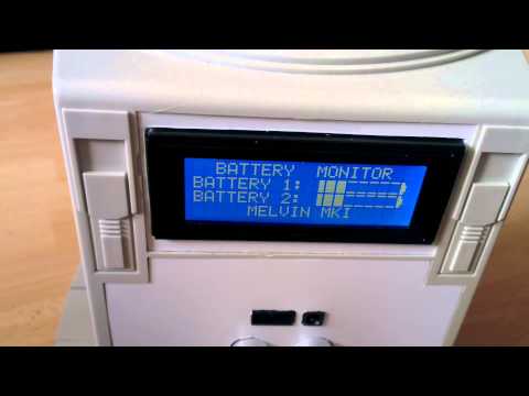
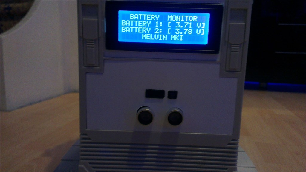
The LCD was the last thing, so it's quite hard to backtrack but testing it earlier showed when both neck servos are in use the LCD goes off. I can take out one extension from all of the head cables which will mean the servos go direct to the EZ-B with no extensions on, they are on there because I didn't know where the EZ-B was going to be mounted until earlier today but I have plenty of space so can mount it where I can reduce the lengths of the cables for practically all of the servos and sensors.
After looking at it all earlier I have my doubts about some of the extensions. The first batch I got are quite flimsy as opposed to the latest batch which are stiff and thicker. I may replace all of the first ones. It may also explain why my ultra sonic sensor can have a mind of it's own sometimes since that was wired with the first batch of cables too (that may pose a problem to re-wire as it's firmly glued in place, but I may be able to just about get at it.
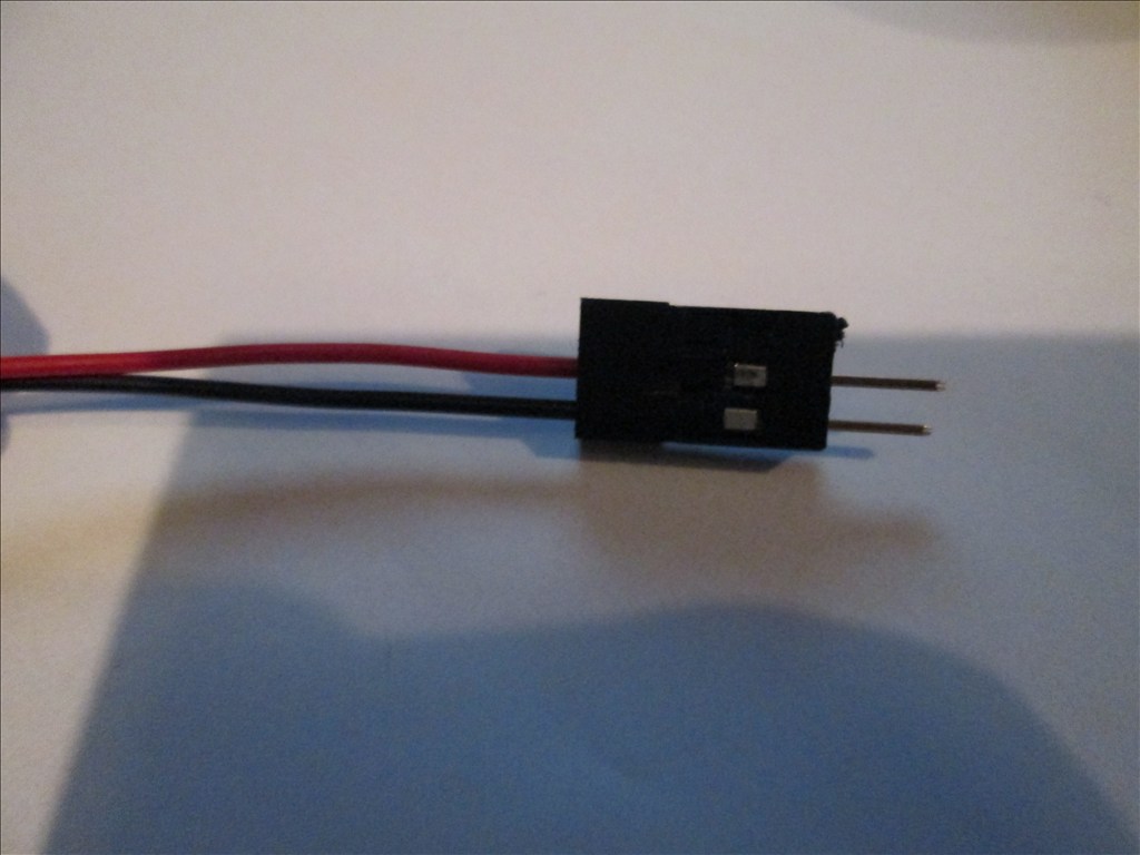
All connections are pre-made JST plugs/sockets with short flyleads so I don't think they are the problem. And where it powers the EZ-B and the 6V circuit the cable is soldered in a Y, all heat shrink sleeved up so I doubt that's the problem either.
Now, after looking at it all I would say chances are it's the first batch of servo cables not being up to scratch and possibly the length of some of the cables. All easy to change though and better to do it now than once I've tidied up the insides.
Has anyone had issues with cheap, poor quality servo extension cables? Or am I barking up the wrong tree with that thought?
Edit: Yes, I just read MovieMaker's post about his ping sensors not working properly and it looks like that was due to bad extensions. I guess I have found the problem... Will change the neck cables tomorrow and test, hopefully with good results
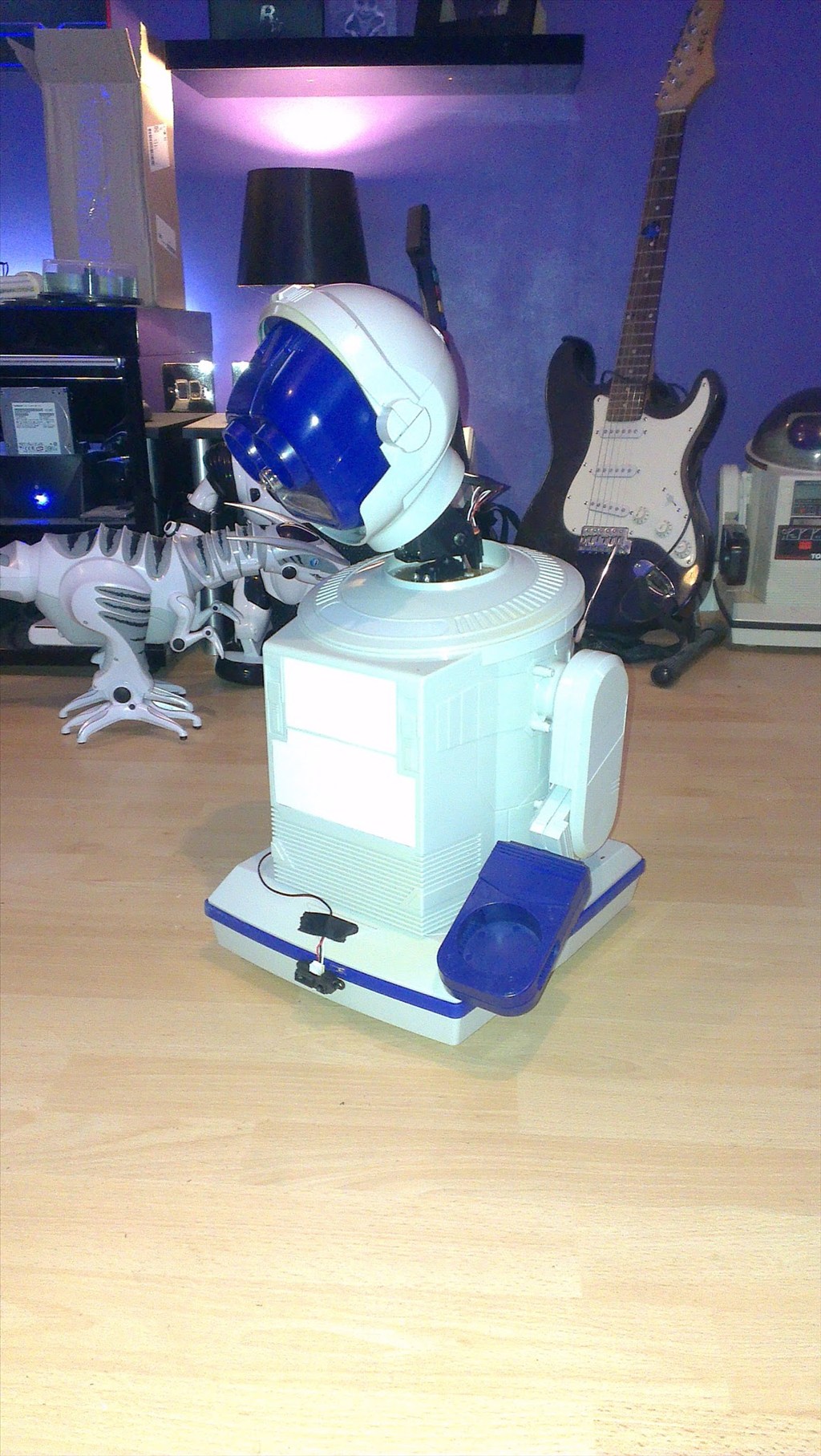
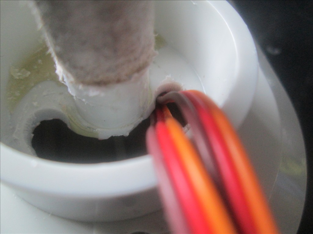
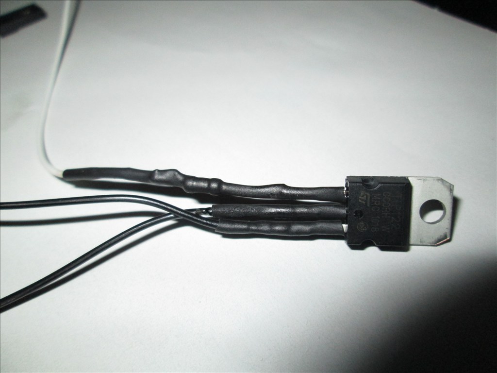
I had problems with cheap servo cables in a RC plane. The ailerons had a mind of their own. I looked at the picture of your robot, and the servo wire I had was the color of the one you have taped up, going up the robot. It's the brown, red, and orange colored wire.
If you are looking for a good, and very flexible wire for the power try silicone wire. They are great for lipos.
Den
I would use a seperate battery for servo's and one for EZB and place a large filter on the servo line another might be needed is a inductor
The extensions are all Black/Red/White, those Brown/Red/Orange are the servo wires coming directly from the 2 MG servos in the neck.
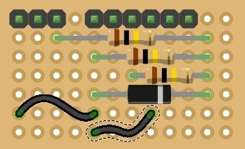
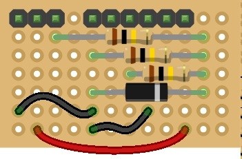
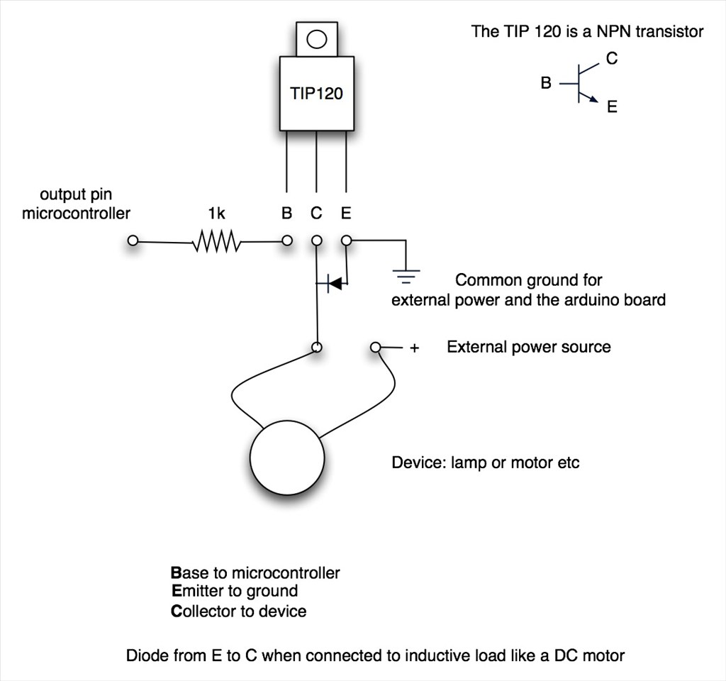
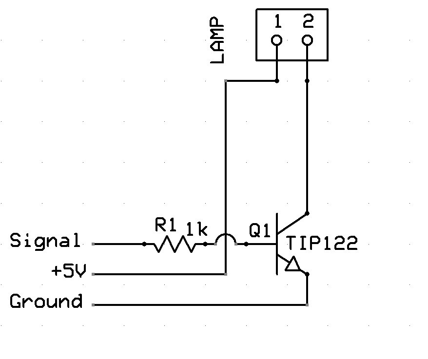
The crappy cables are just far too flimsy I expect, and if memory serves me correctly I had 10 of them, 2 for the head pan/tilt, 4 to the old HBridge (now changed) and 2 to the Ping. Not sure on the other 2, probably on the TIP circuits for the old eyes and mouth - I hope so as otherwise I have no idea where I used the other 2.
I'm going to start by changing/removing the crappy cables and testing to see what happens, I am 90% sure that it will solve the problem since reading about issues with poor quality cables.
Rich, it is my gut feeling that its not the cables that are causing your problem
Here is my logic on this, you are getting a reset on the LCD when certain servos are working, this indicates that the 5V rail is "crowbaring". Now bad cables to servo's would have no impact on the LCD unless you (piggyback) fed the LCD from the servo 5V supply (at the servo end) and it is unlikely that you would do that. If the servo cables are bad in some way they are only going to impact on the things connected to the other end of the cable like servo etc.
What I think may be happening is the EZ-B 5V regulator (rated at 3amps) is dropping out on overload when your heavy duty servos pull a large start current. Also the LCD backlight draws around 70mA, you can turn this off by taking out the command code 19 which is turn backlight on, its off by default.
i2cWrite(0,0xc6,0,12,4,19)
With the blue display it will hard to see anything with the backlight off, but it would be interesting to see if the LCD still resets?
I think your problem will be solved when you feed the LCD from a separate (non servo) 5V power source. Also a large reservoir cap across the LCD may also help the problem as the stored energy in the cap will limit the drop-out voltage on the LCD power rail during the in-rush current spike caused by the servos starting.
Hope this helps.
Your logic makes total sense, however I will be swapping the cables and shortening them for neatness inside the robot too.
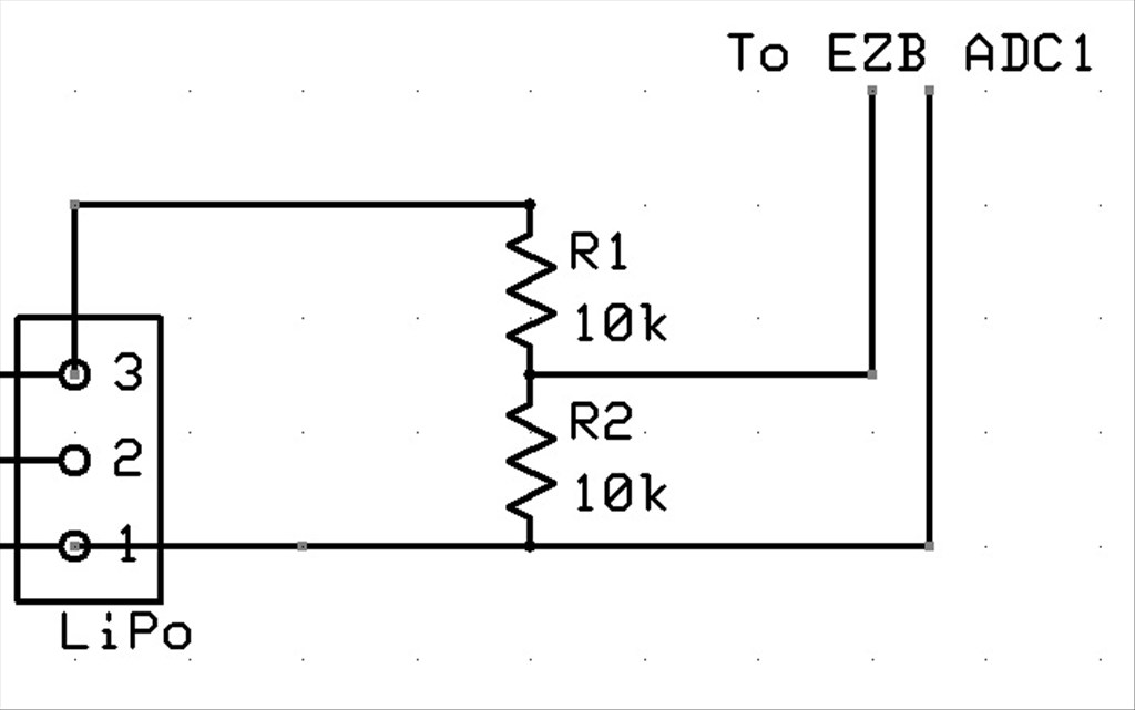
I have already dimmed the backlight to the dimmest that is still visible, I'll try it with it off later and see what happens. However the reservoir capacitor idea is a simple, quick addition which should solve it. Belt and braces I may add one anyway even if I move the VCC and Ground to an external 5V supply (which may prove a problem since I have 6V from the regulator or 6.6V-8.4V from the LiPo) or move the 2 servos to the 6V supply.
All suggestions are a great help and appreciated, thank you