


Now I have the EZ-B kit and the Hearoid it's time to start my Showcase thread.
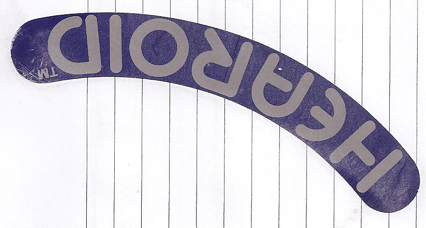
I still haven't decided on a name for him yet, all suggestions are welcome.
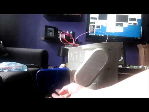
I won this robot on ebay weeks ago, for the past 2 weeks he has been waiting for me to collect him...
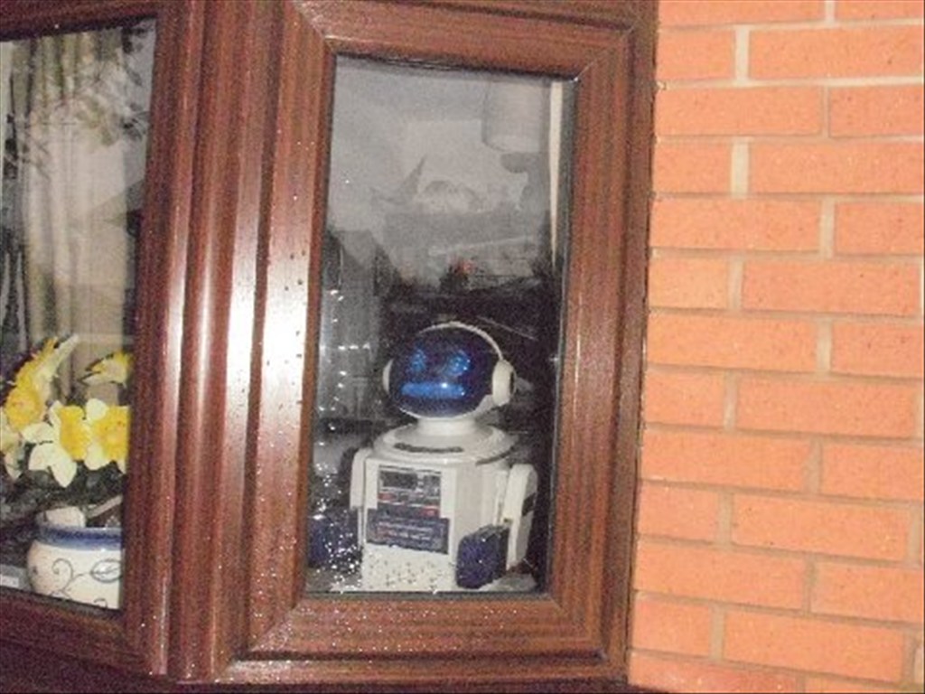
Today was the day, a road trip to pick him up and bring him back to his new home...
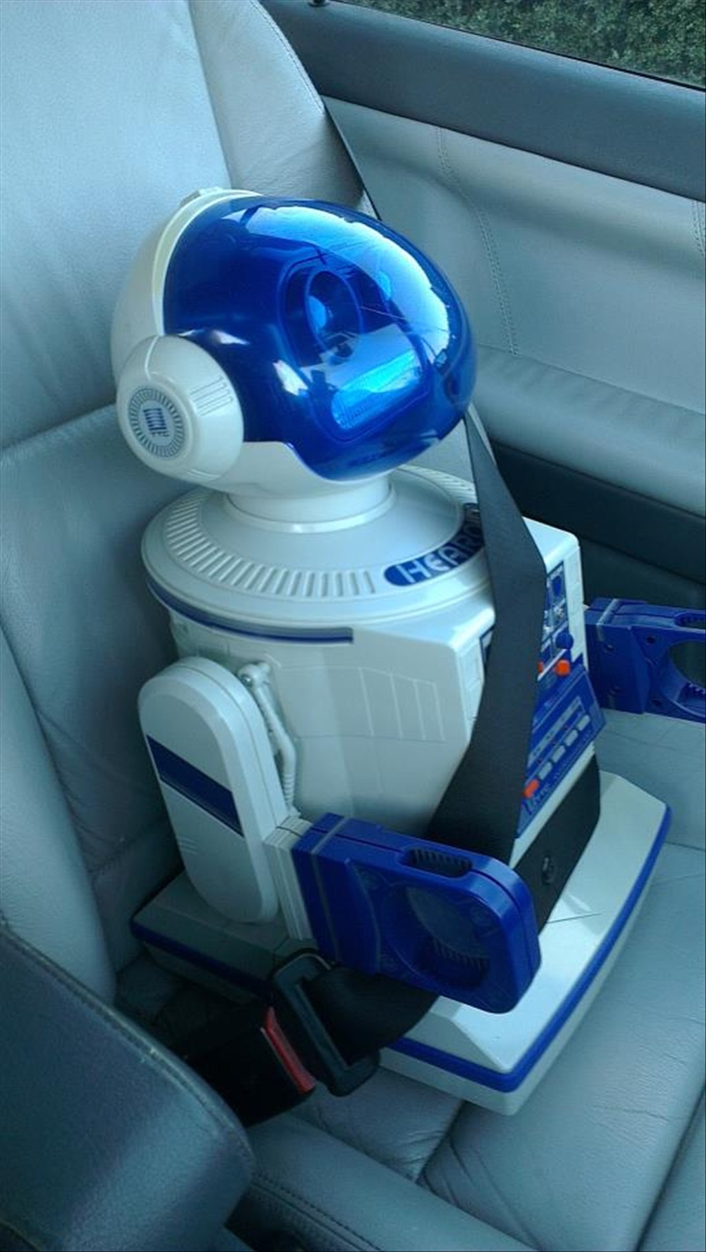
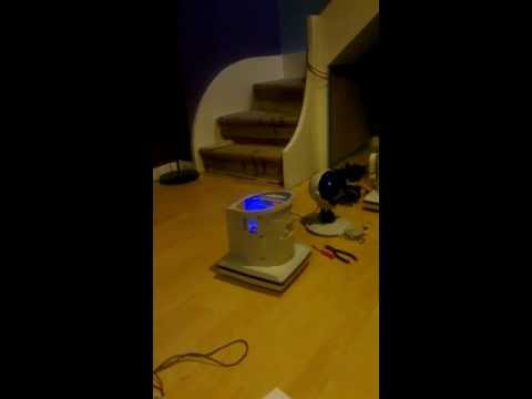
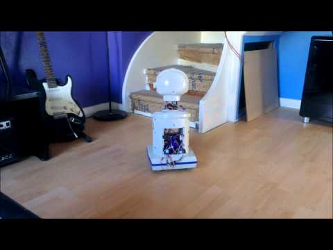
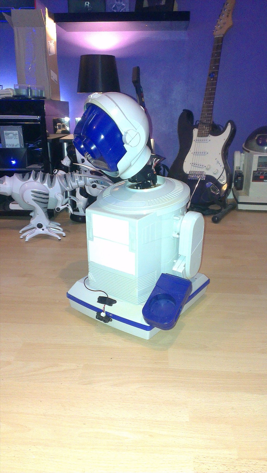
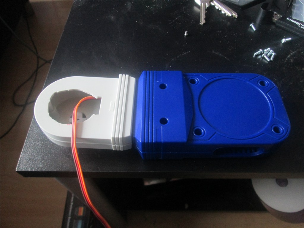
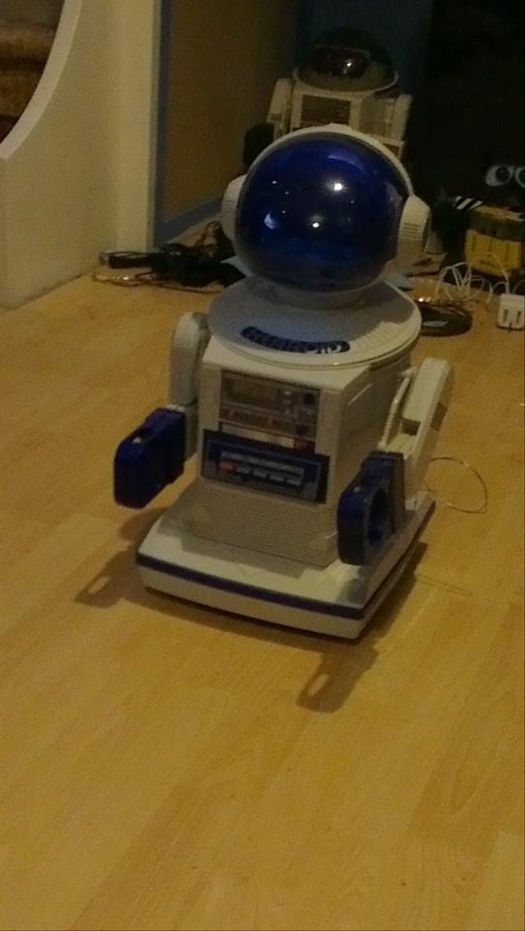
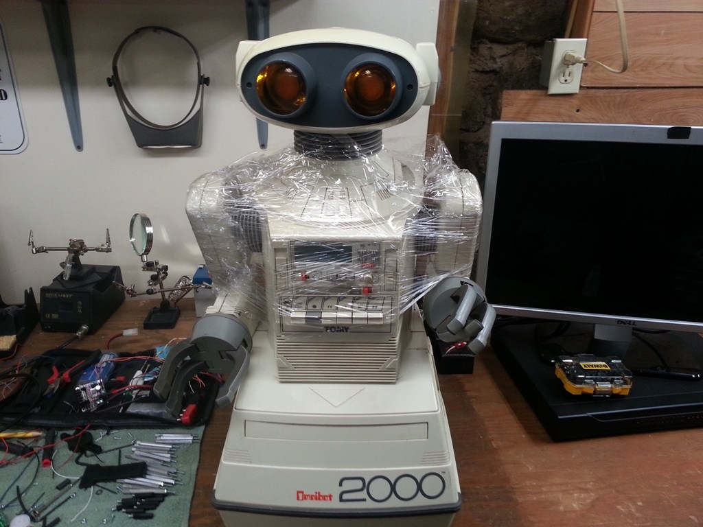
In his new home (with Omnibot and Wall-e in the background totally unaware they are next in line to be opened up)
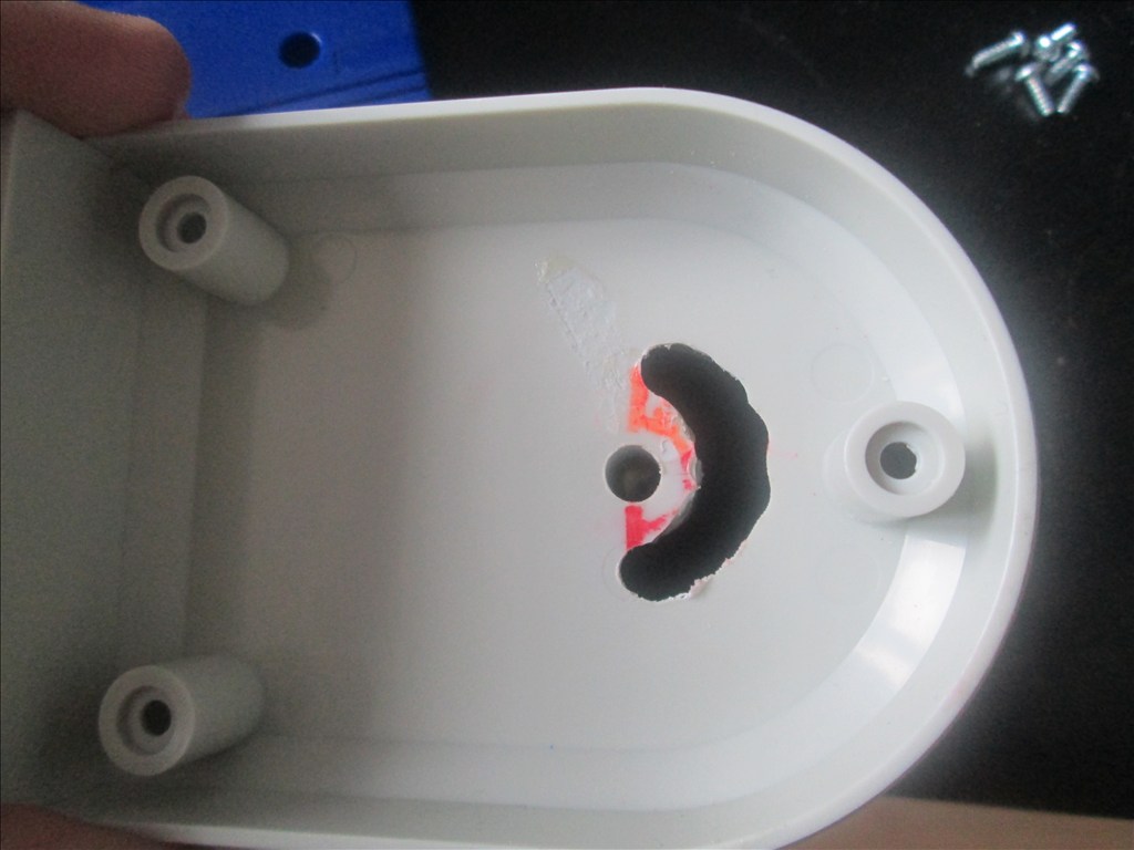
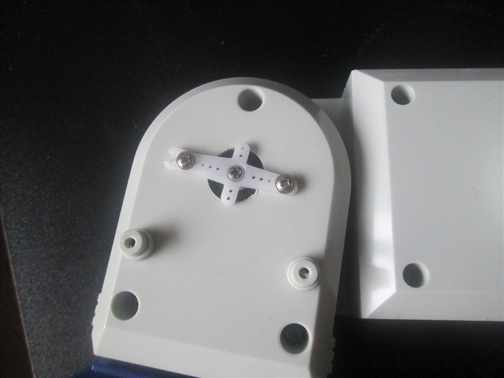
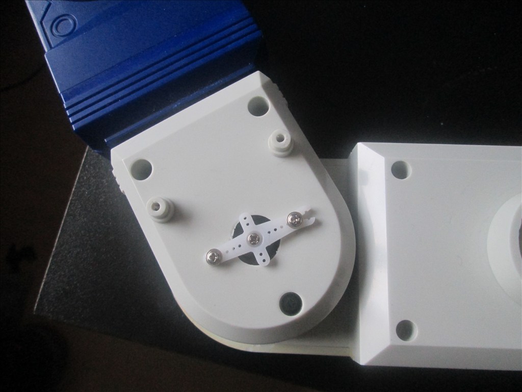
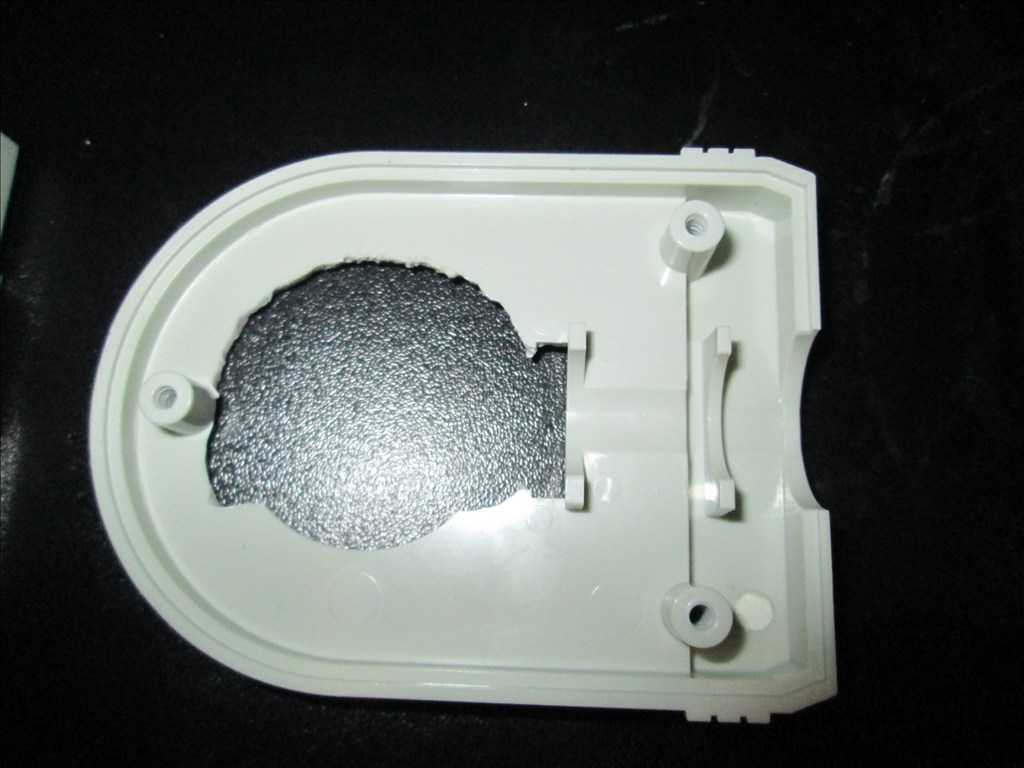
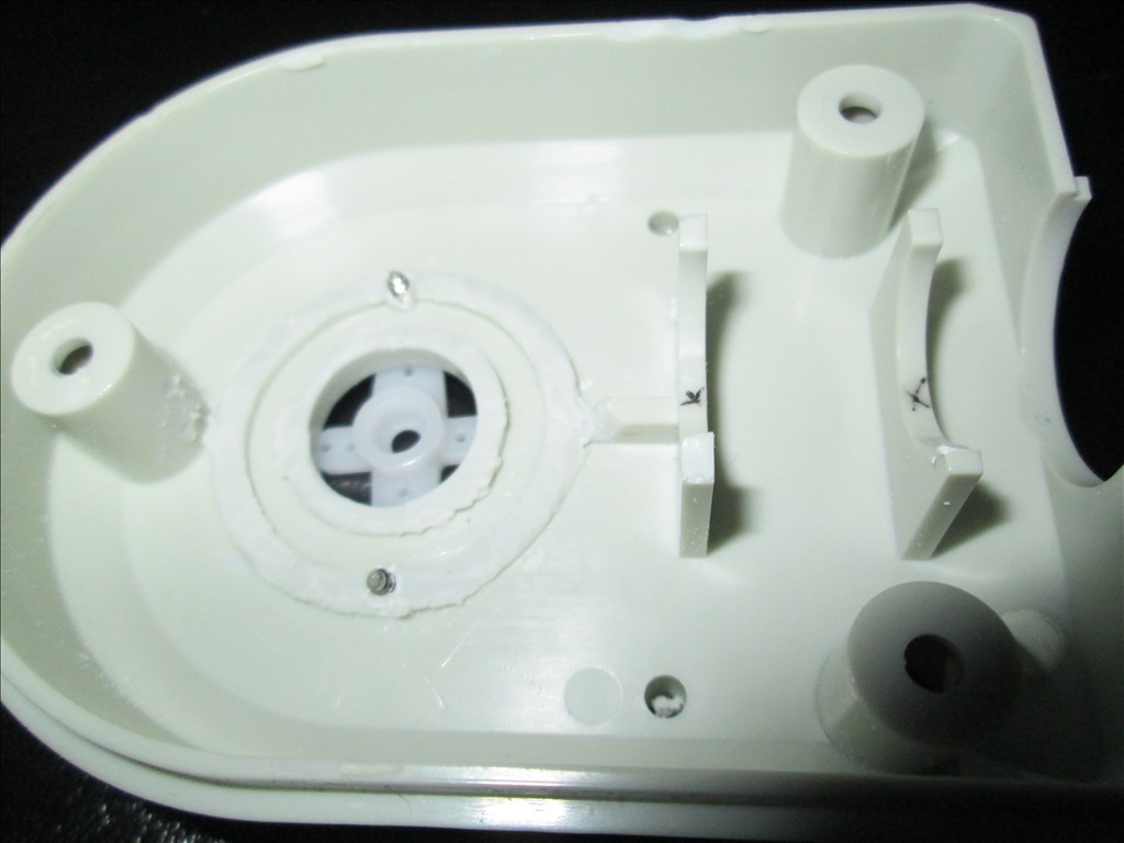
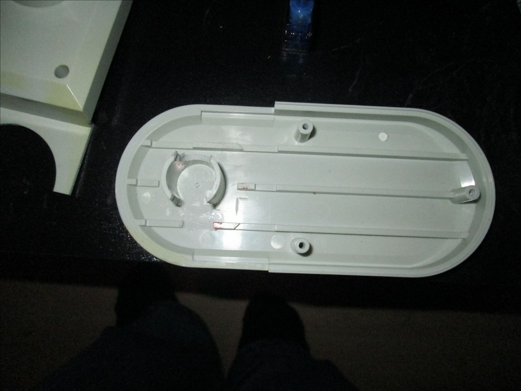
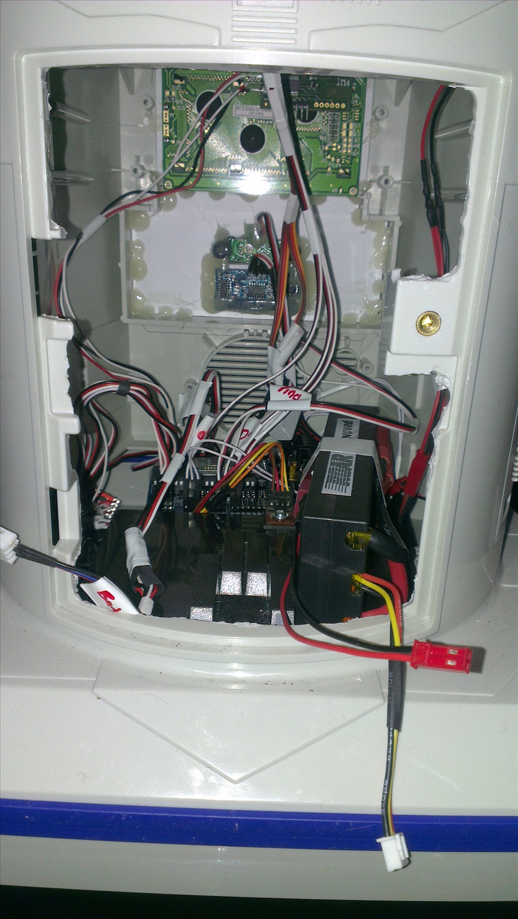
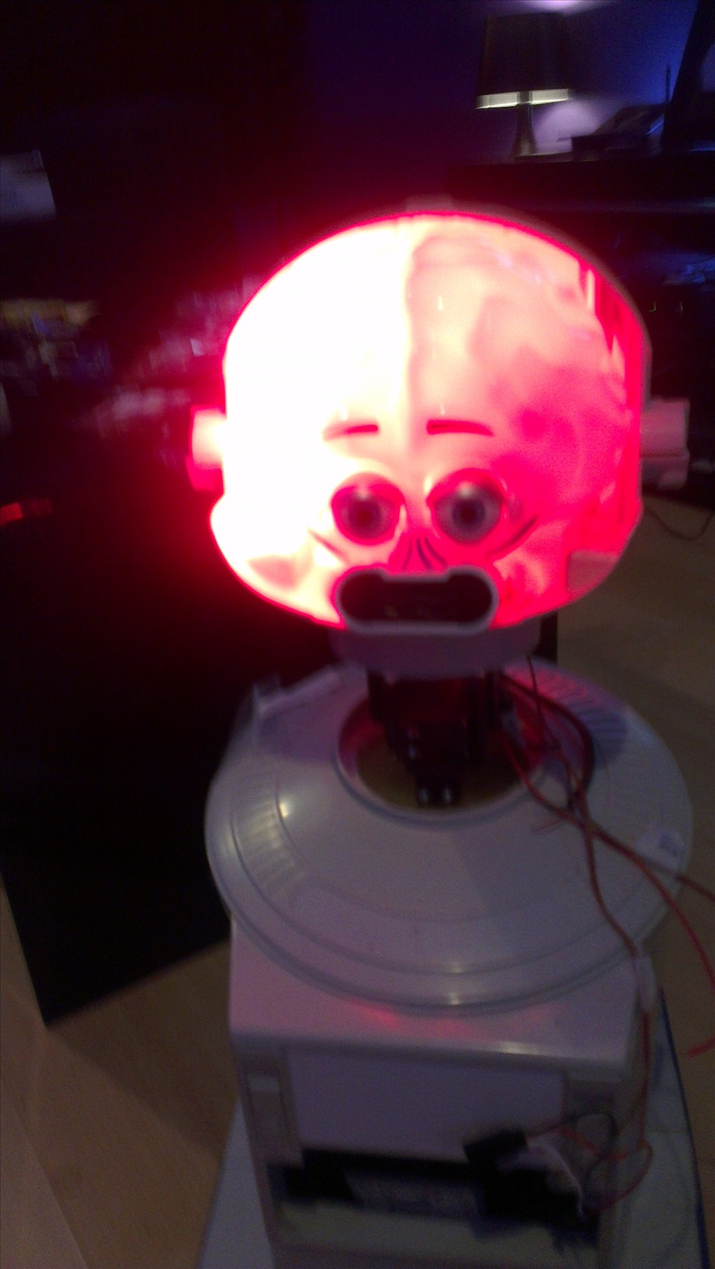
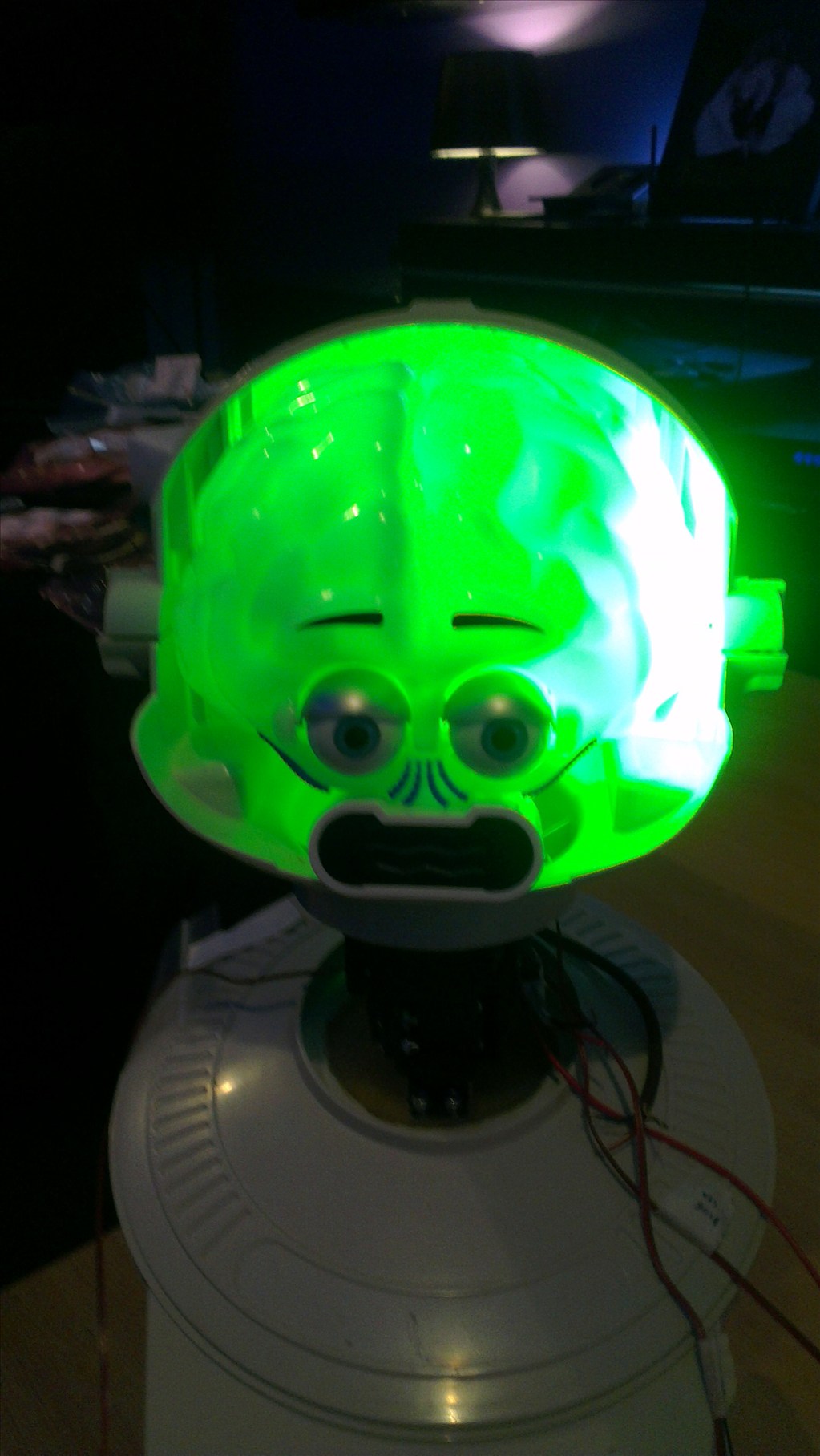
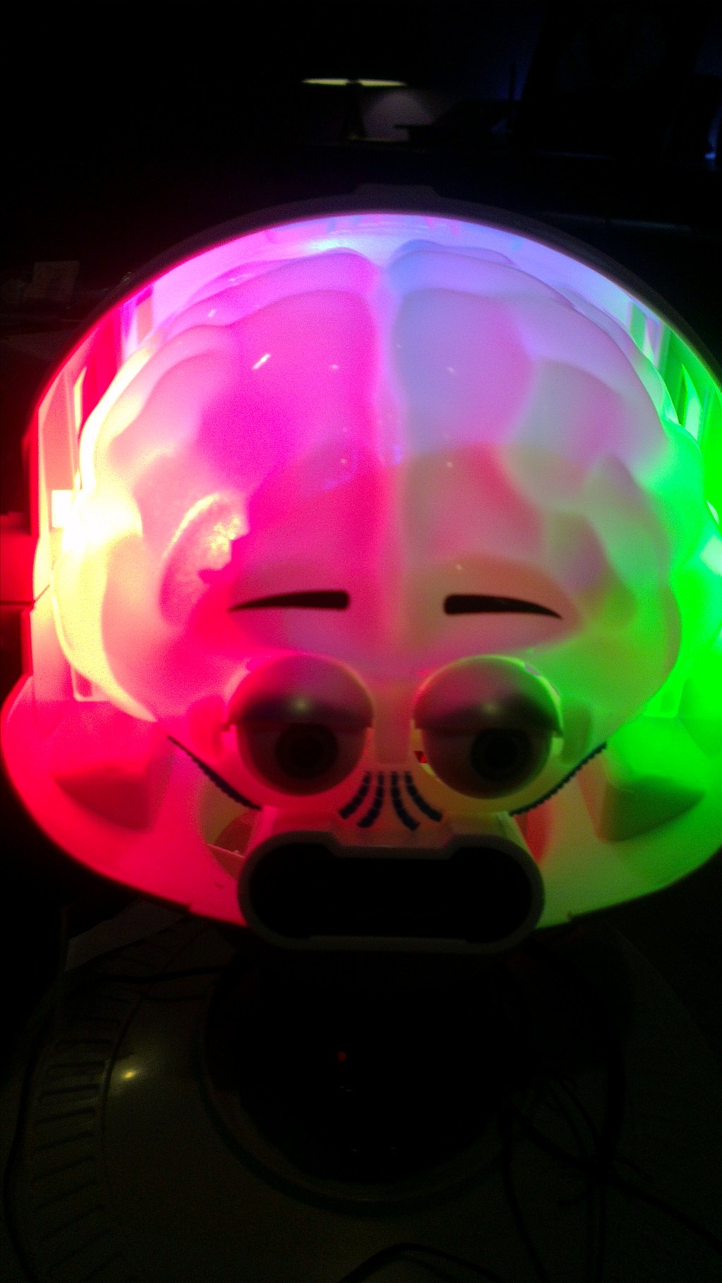
It wasn't long before this happened...
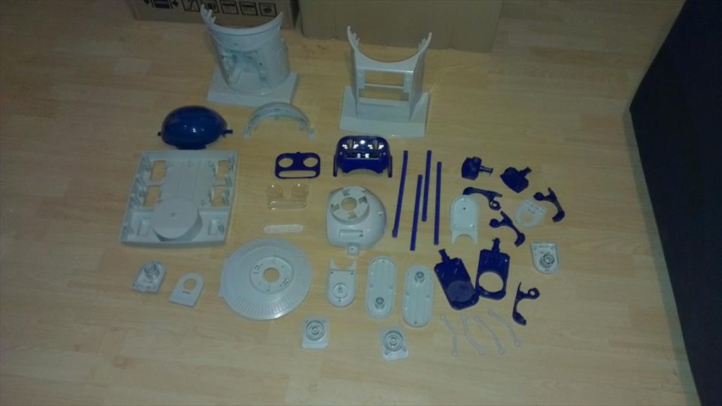
Now waiting to go in the dishwasher to get nice and clean.
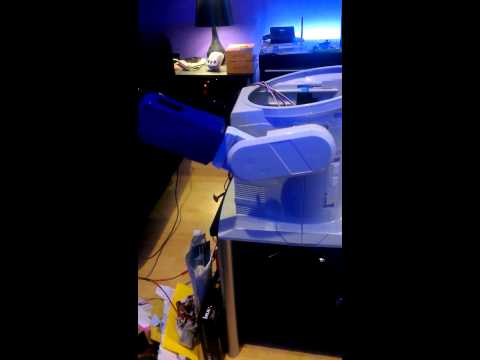
The plan is to make him autonomous, running 24/7 (except for when he knows to go charge himself up) but will also be adding in the various image tracking options.
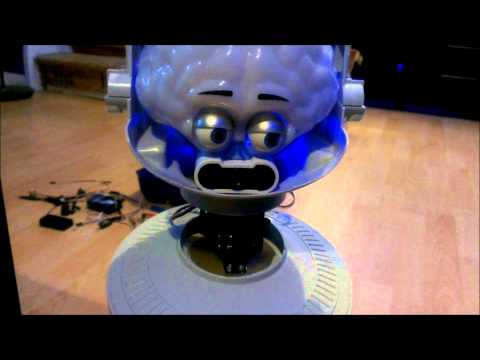
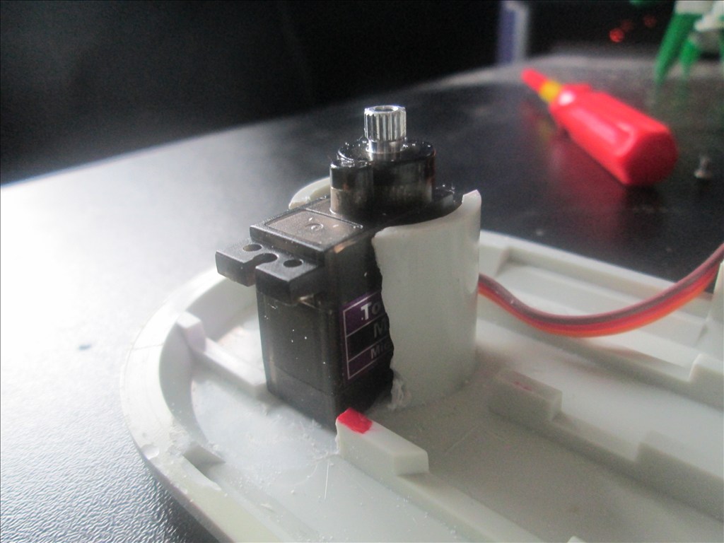
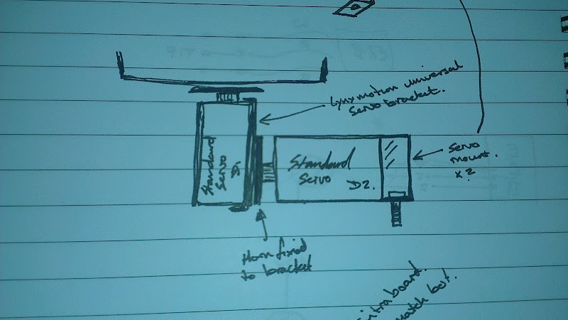
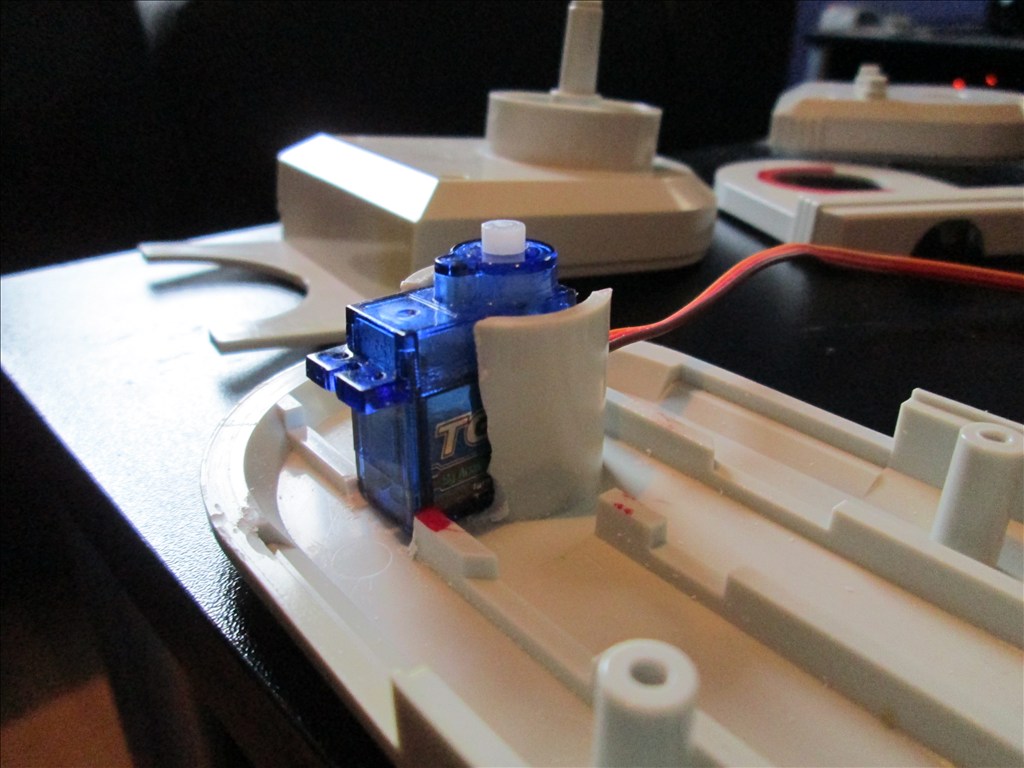
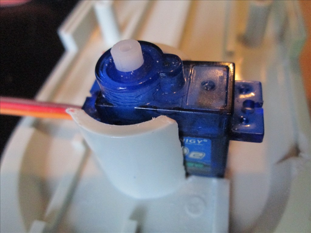
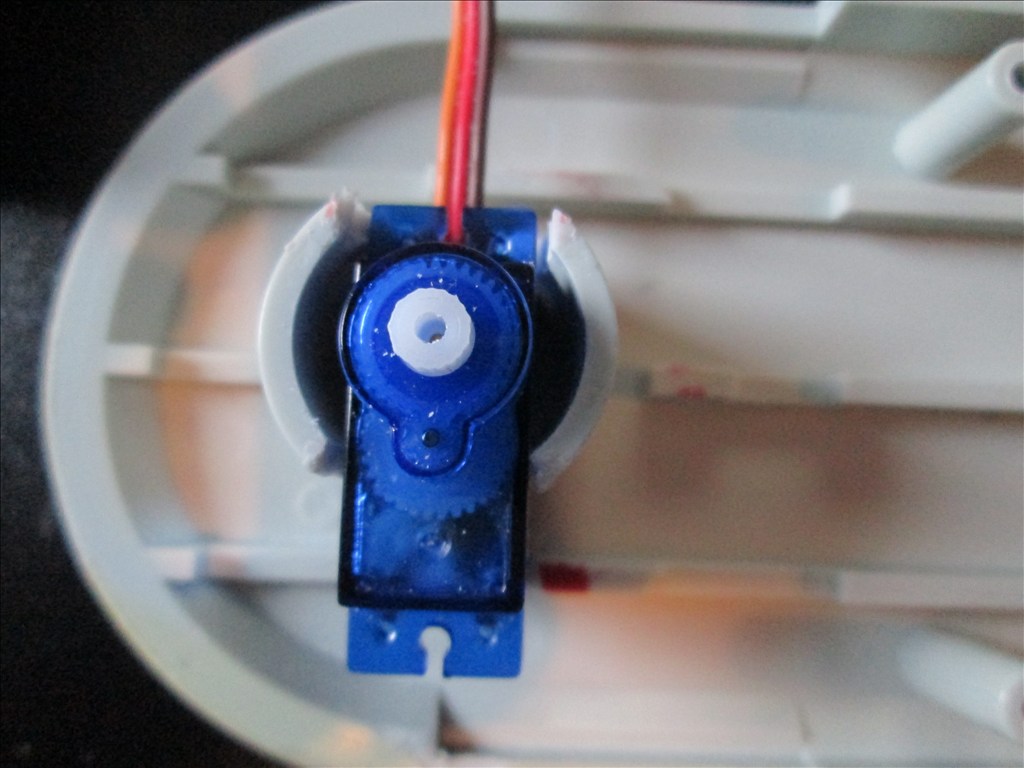
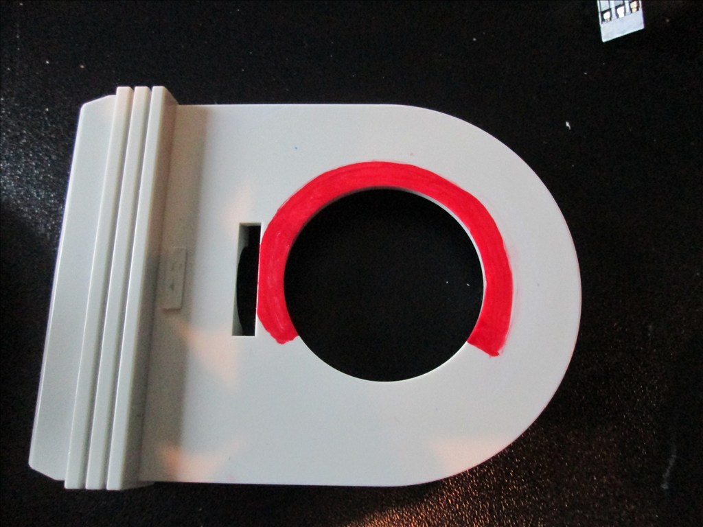
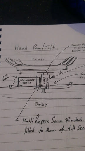
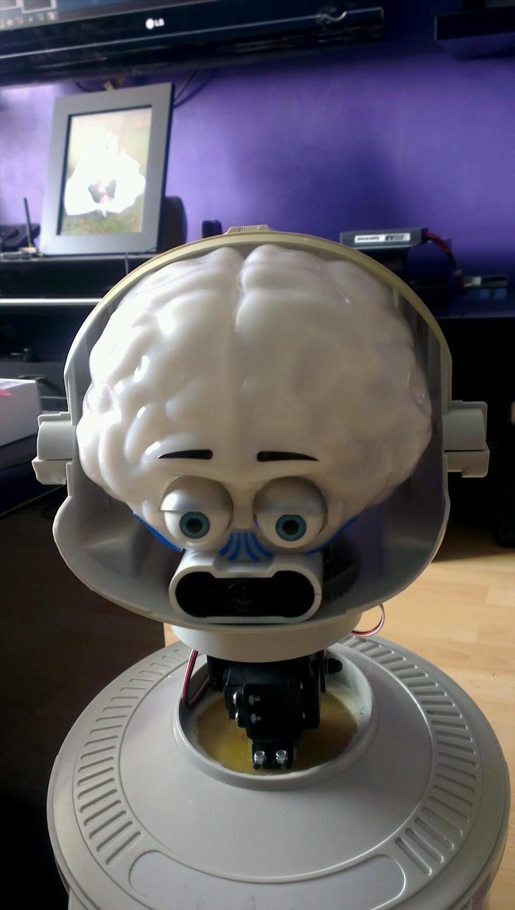
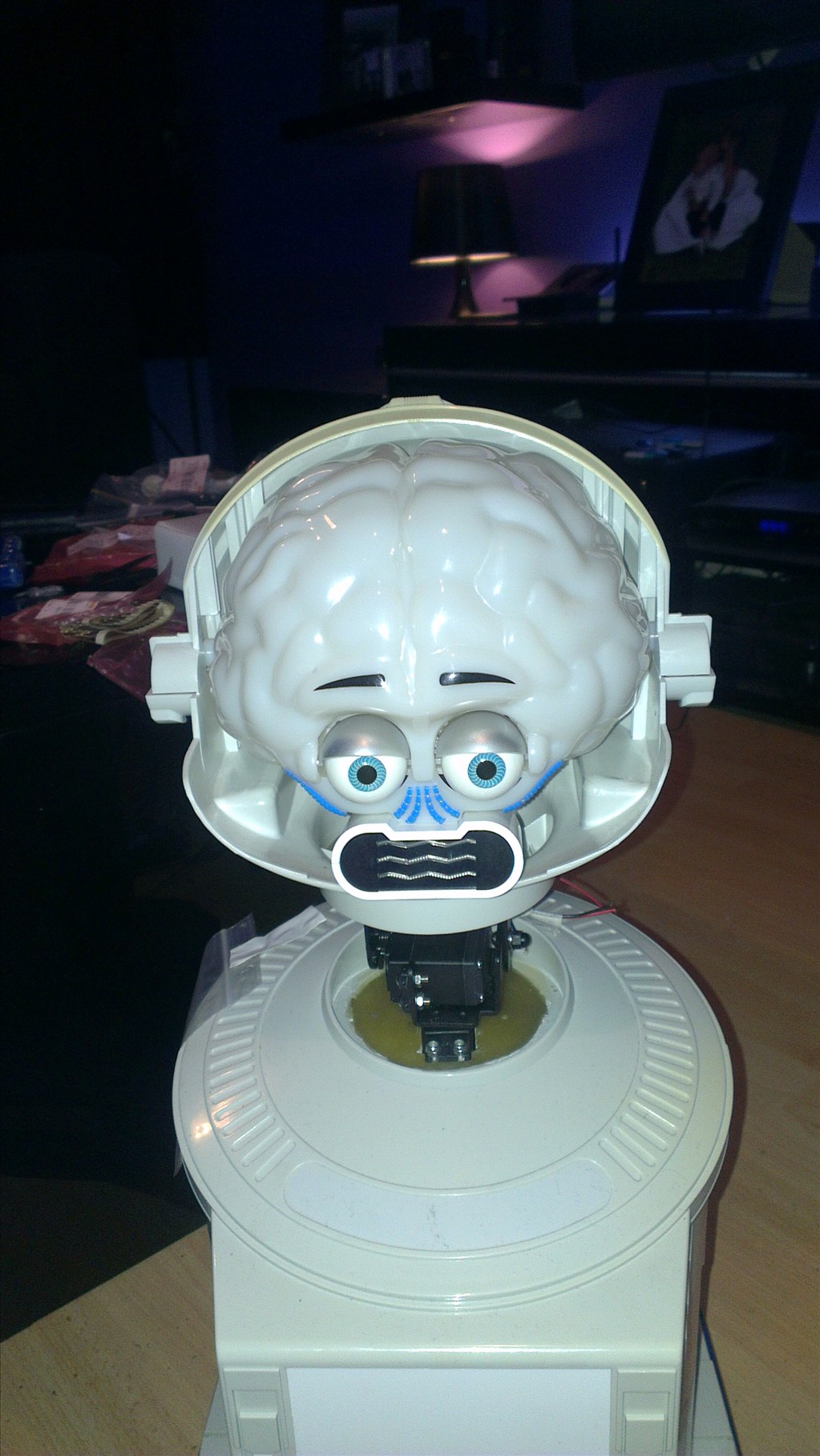
The only other slight modifications to be made to him are to convert the head to tilt & pan which will involve having to give him a small neck.
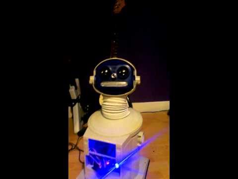
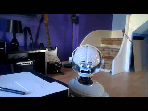
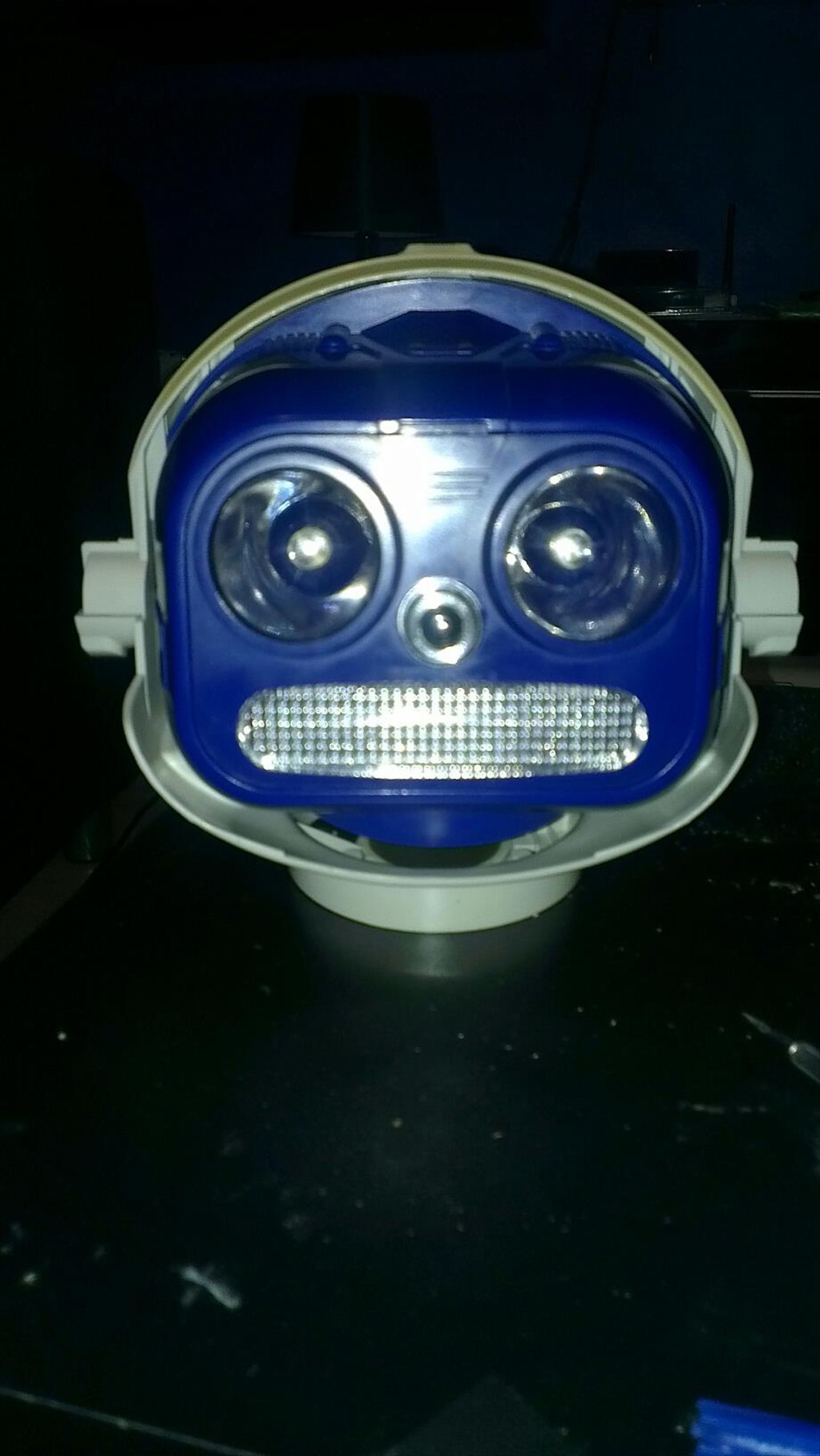
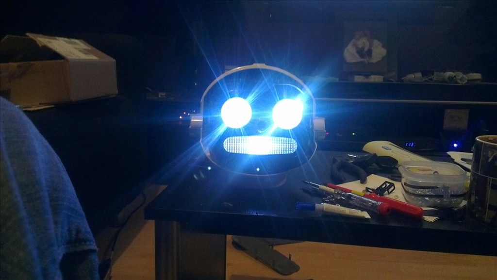
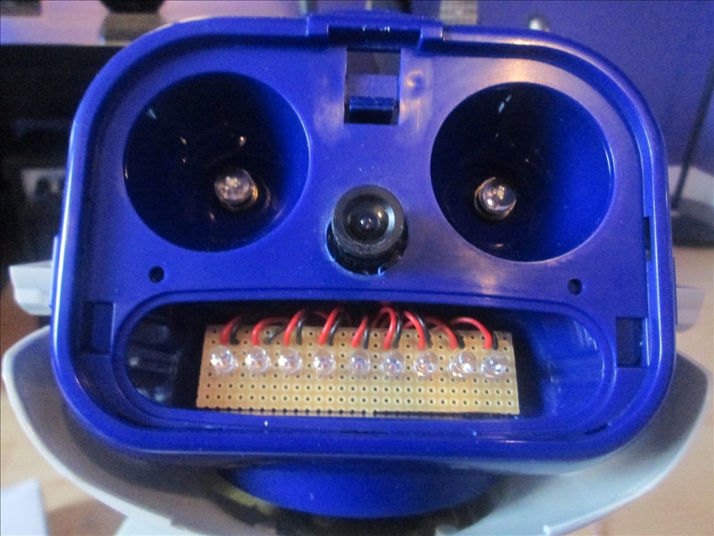
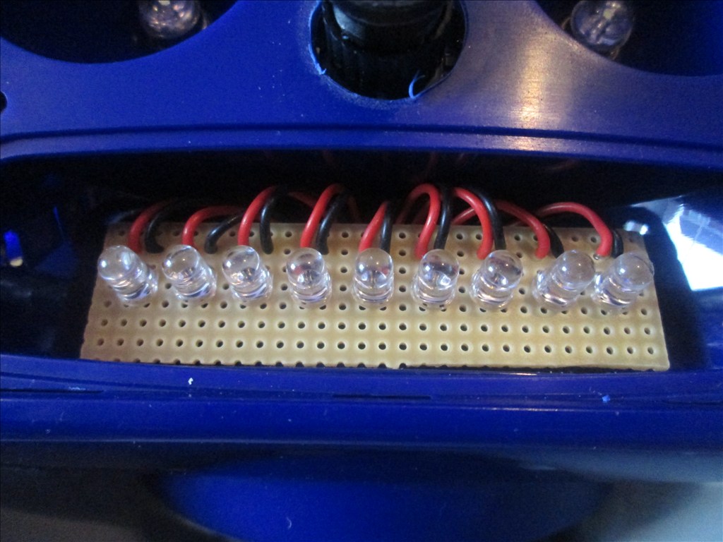
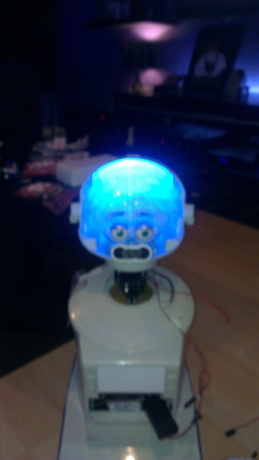
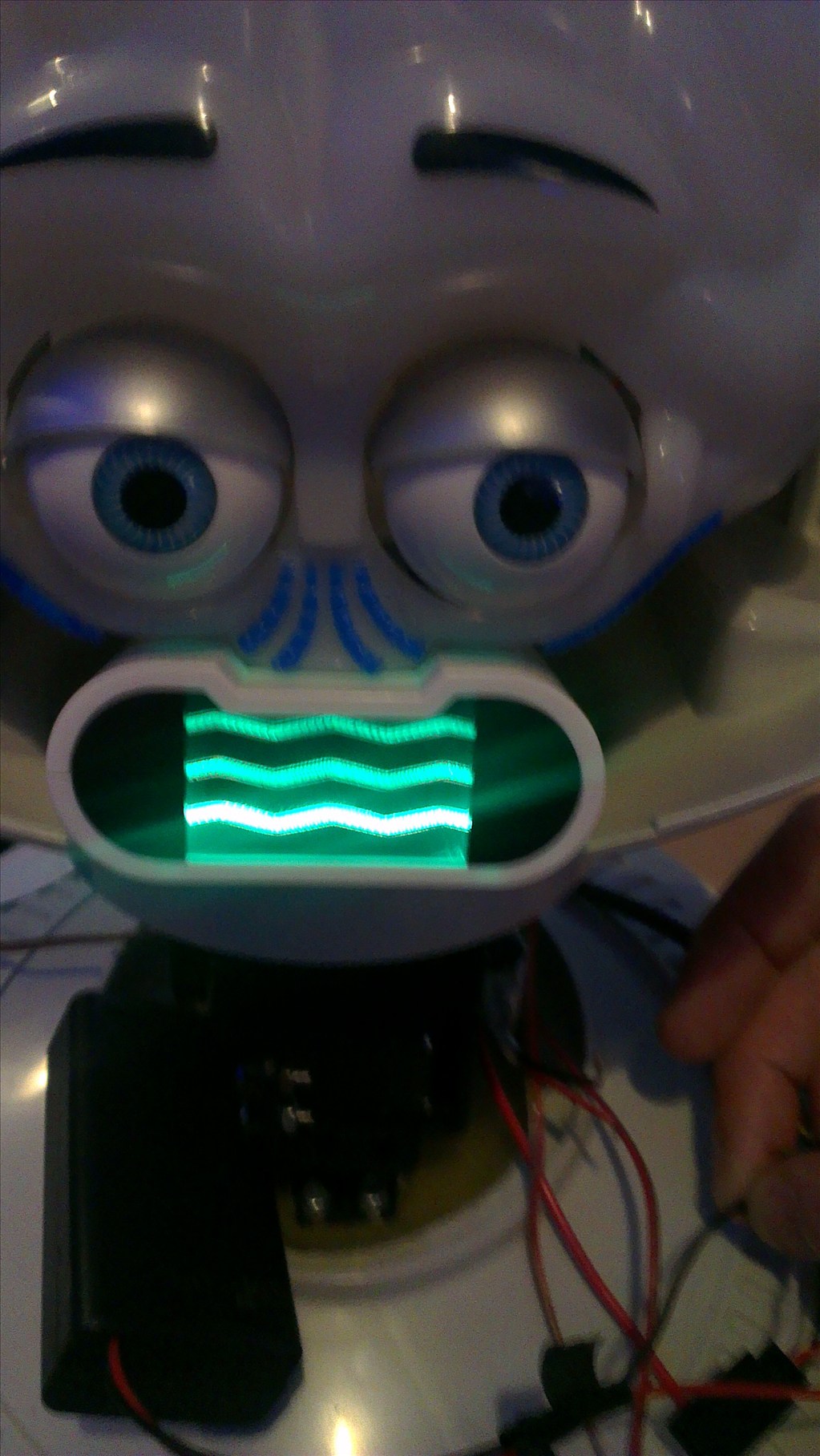
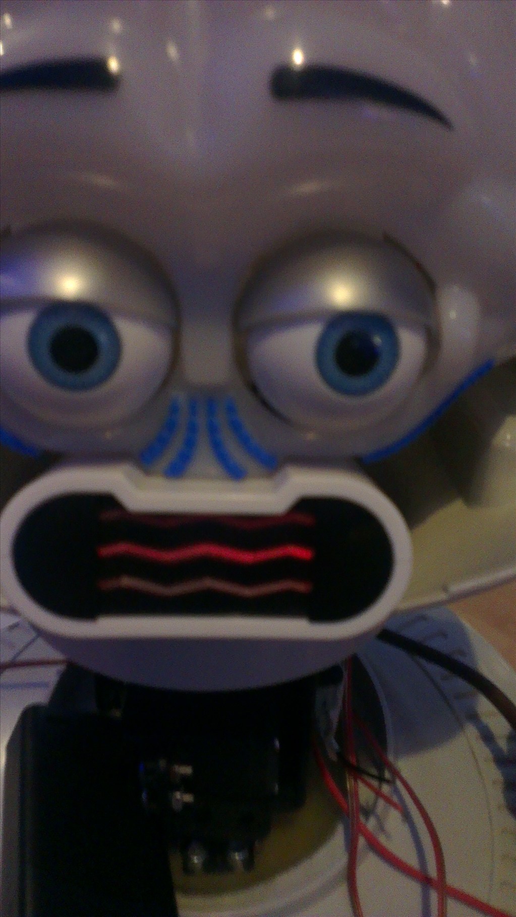
The head will include the camera. I haven't yet decided to fit it in one of his eyes or to make it his nose. The issue to overcome with this is the blue tint on the bubble head. The mouth will have a light or some lights in which flicker when he speaks.
The arms will be given some life with servos at the shoulder joints and the elbows provided I can get them to fit in there nicely.
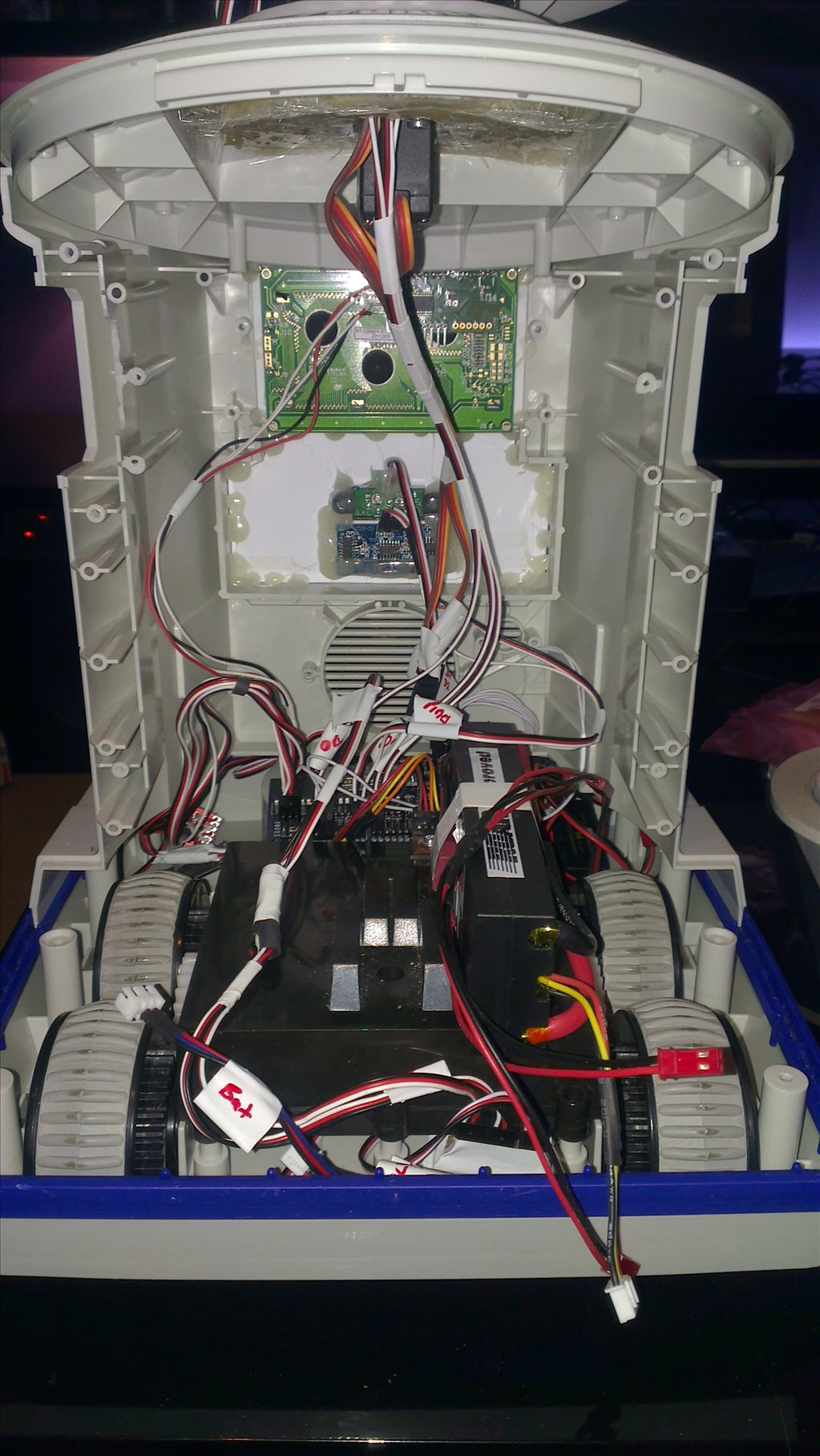
Ultrasonic sensor will be in his chest, probably on a servo to give a wider view.
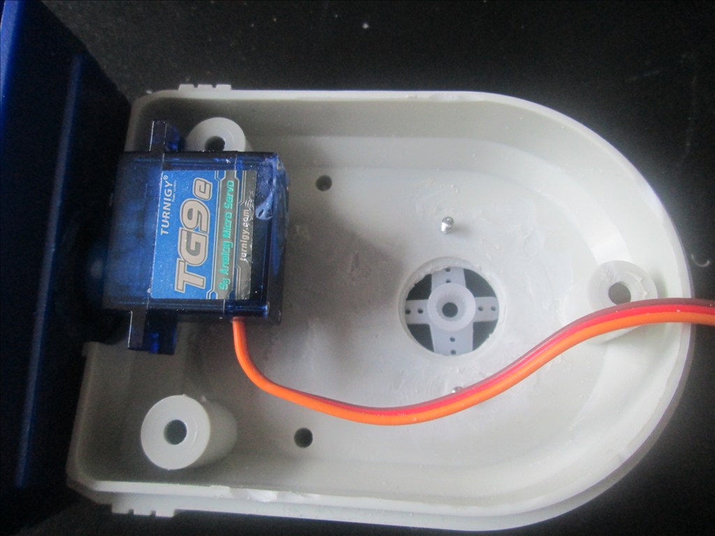
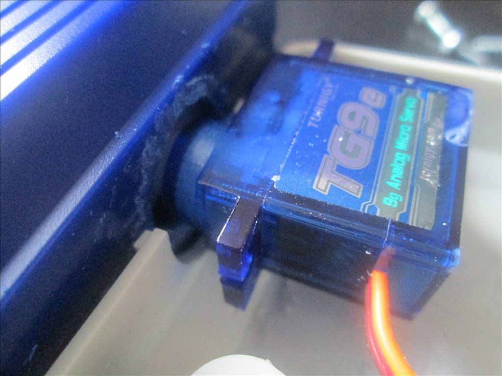
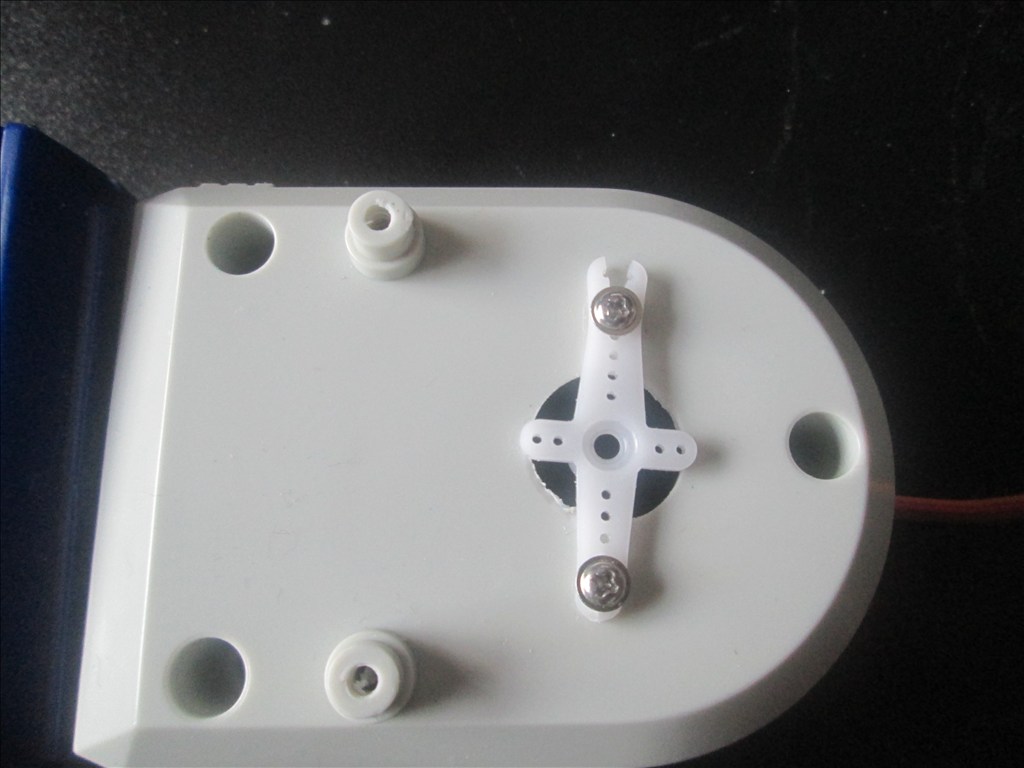
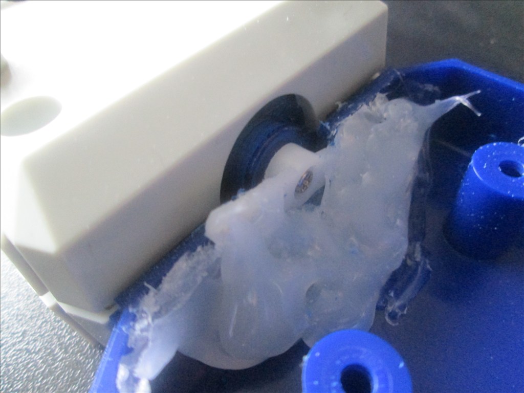
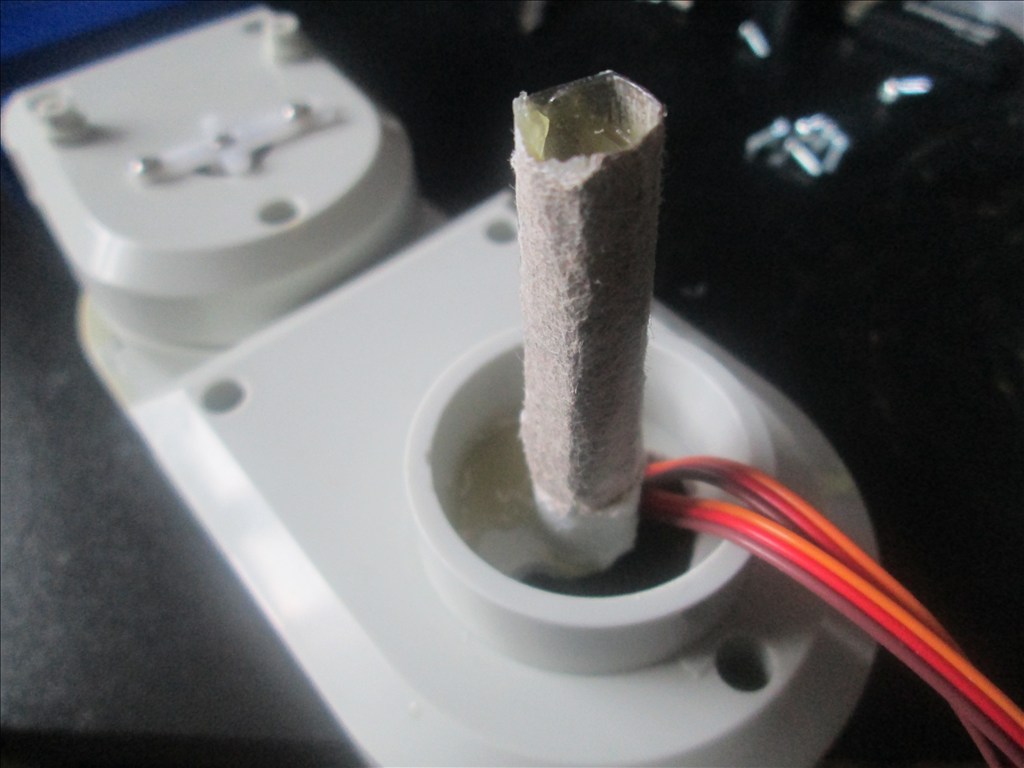
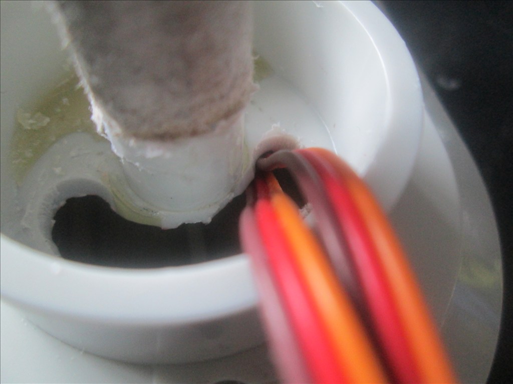
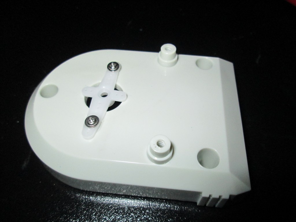
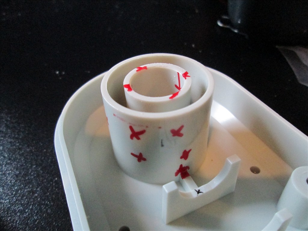
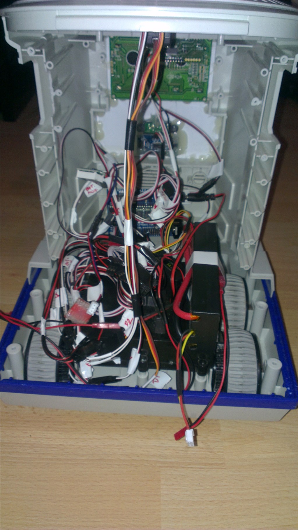
Original drive wheels and gearbox seem to be in very good shape so will plan to reuse those and just replace the existing motors for the modified servos if they can manage the task.
Speaker and microphone will be in the original positions - if it's not broke why fix it?
Not too big a project but enough to give me a test, help me learn and bring an old robot back to life.
Discover more robots
Charleybot's Project Multi-Omnibots 2000
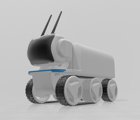
Jstarne1's Levi Rover Modular Robot 3D Print


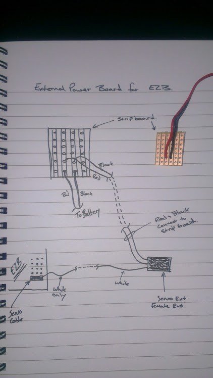
I was nervous at first, and safety is always a concern. But, I have well over 150 cycles on my batteries, and they are still working well. Being that the charger is going to be built into the robot charging in your house, I would feel safer charging it at a lower current. Also, I charge mine outside.
A good inexpensive battery can be found at hobbyking.com. The nano tech batteries they sell are excellent.
One question Rich? I noticed in one of your videos of your robot moving across the floor. When the ping or IR detector picks up an object, and the robot turns 45 degrees before moving forward again, did you program script for it to turn that much before going forward again?
Thanks,
Den
Yes, it's my basic IR script. It needs setting up properly as when I wrote it I didn't know the time needed for the turn amount. However, it will be changing a lot too once the two IR sensors on the corners are fitted as these will be used to aid the robot in deciding which way to turn.
I think I have shared the script on the cloud, if not it's posted in the scripting section and may even be in this topic somewhere. It's easy to adjust as I use variables at the start of the script rather than using numbers on the commands, not only because I share them and like to make it as easy for others as possible but also for this reason, setting it all up and tweaking the angles and distances etc.
I found that hobbyking.com has a much better prices on batteries,i just ordered some LI-POLY for lynxmotion johnny five design
lynxmotion johnny five design
Thank you!
Den
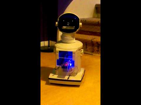
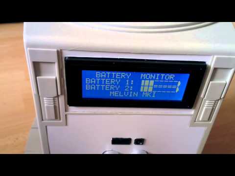
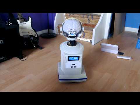
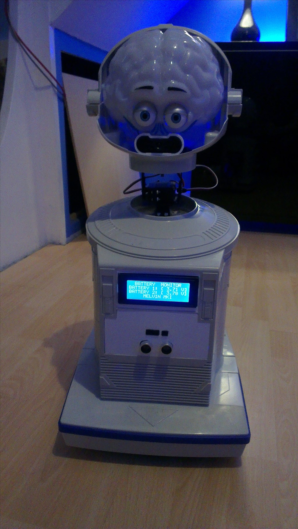
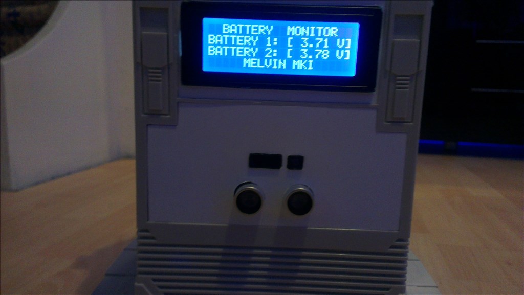
Good job Rich with LCD monitor, it seems that with proper scheduling can make almost anything I like.
Rich, that display looks great, nice work!
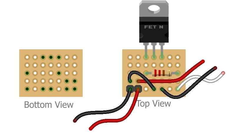
I think your display resetting is caused by the start (in-rush) current of the servo's - this can be up to 7 times the run current of the servo depending on the mechanical load the motor has. One possible fix is to place a large electrolytic capacitor on the display feed, this will act as a reservoir cap and reduce the large voltage dip (that is resetting the display). You could try values around 1000uF or 2200uF
This could also be showing that you batteries are unable to take the load of the servo motor starting maybe they need charging or you need a greater ampere hour rating.
Hope this helps.
Thanks Tony, I'll give the capacitor a go since after fully charging the 5000mAh battery it is still cutting out when the servos move (only the neck, the eyes are fine) and when the drive motors are working.
I might try using both 5000mAh batteries in there at the same time for a whopping 10,000mAh to see if that helps, or maybe feeding the LCD's VCC direct from the battery rather than through the EZ-B (if I can find a low cost 5v regulator). But will try adding the capacitor first since, in theory that should solve it.
I don't need any pull up resistors or anything like that do I? I've assumed not from reading the EZ-B manual and the LCD manual but I've been slightly unsure on that.
The third alternative may be to use the 2nd EZ-B which I may need to run everything I plan to fit (when it comes to the arms and brain lights), one for the high power, high torque servos and anything else which has a high starting current and the other for the I2C LCD and low current devices. But really don't want to have to run 2 EZ-Bs in this robot.
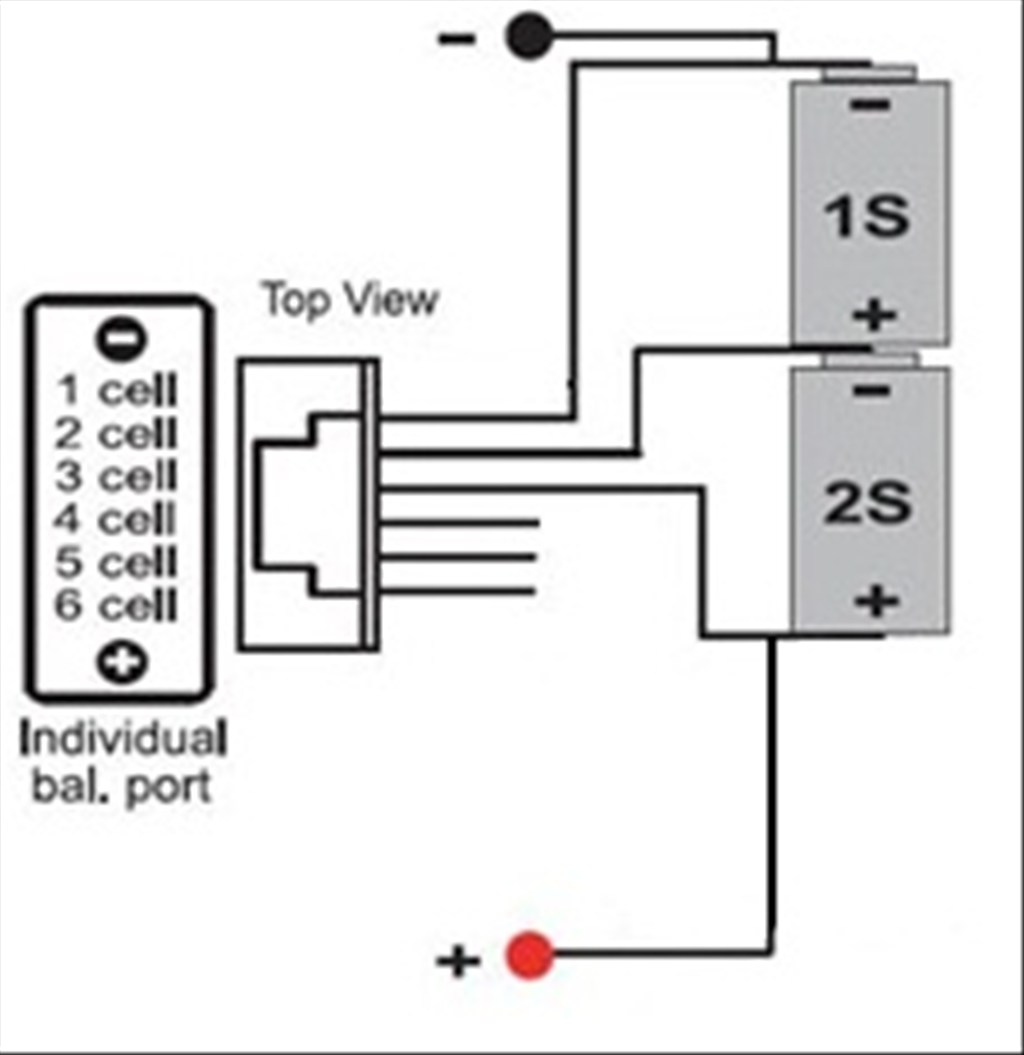
Or, just a final thought, would changing the LiPo battery from a 2S to a 3S help?
Rich, with 5000mAh I am surprised you have the problem, at this rating they should easily handle the servo start current?
I do not think pull-ups are you problem as you said the display resets, so its a brownout probably of the controller PIC on the hybrid back board or it could be the controller (usually Hitachi) on the LCD itself. I was not sure about the I2C pullups on the EZ-B so I added 2 x 1K8 to the header cable that connects to the I2C port.
What may help is if you isolate the servo power from the EZ-B 5v rail, this way your servo feeds directly from the battery, you need to check the servo voltage ratings some I use here are 7V2. Care needs to be taken with this as a fully charged 7V2 battery pack can have a terminal voltage of 8V4 which is well over the max voltage rating. A couple of things possible here are to use a UBEC, Hobbyking do a 7V2 4amp one for around a fiver. Another way is to use series diodes (of the right current rating) where you will lose around 0.7V on a regular diode and around 0.3V on a Schottky. You need to set this up so that with a battery voltage of 8V4 the diodes have a voltage drop of at least 1V2.
What I did to the EZ1 Robots EZ-B board is split my servo channels into 2 separate voltages D0-D7 comes off the EZB supply and D8-D14 comes off the external 7V2 battery. To do this you need to (carefully) cut a PCB track in the middle of the 2 servo headers then add the 7V2 feeder cable on the pads just above the D14 servo header connector.