


Now I have the EZ-B kit and the Hearoid it's time to start my Showcase thread.
I still haven't decided on a name for him yet, all suggestions are welcome.
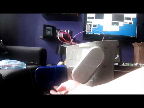
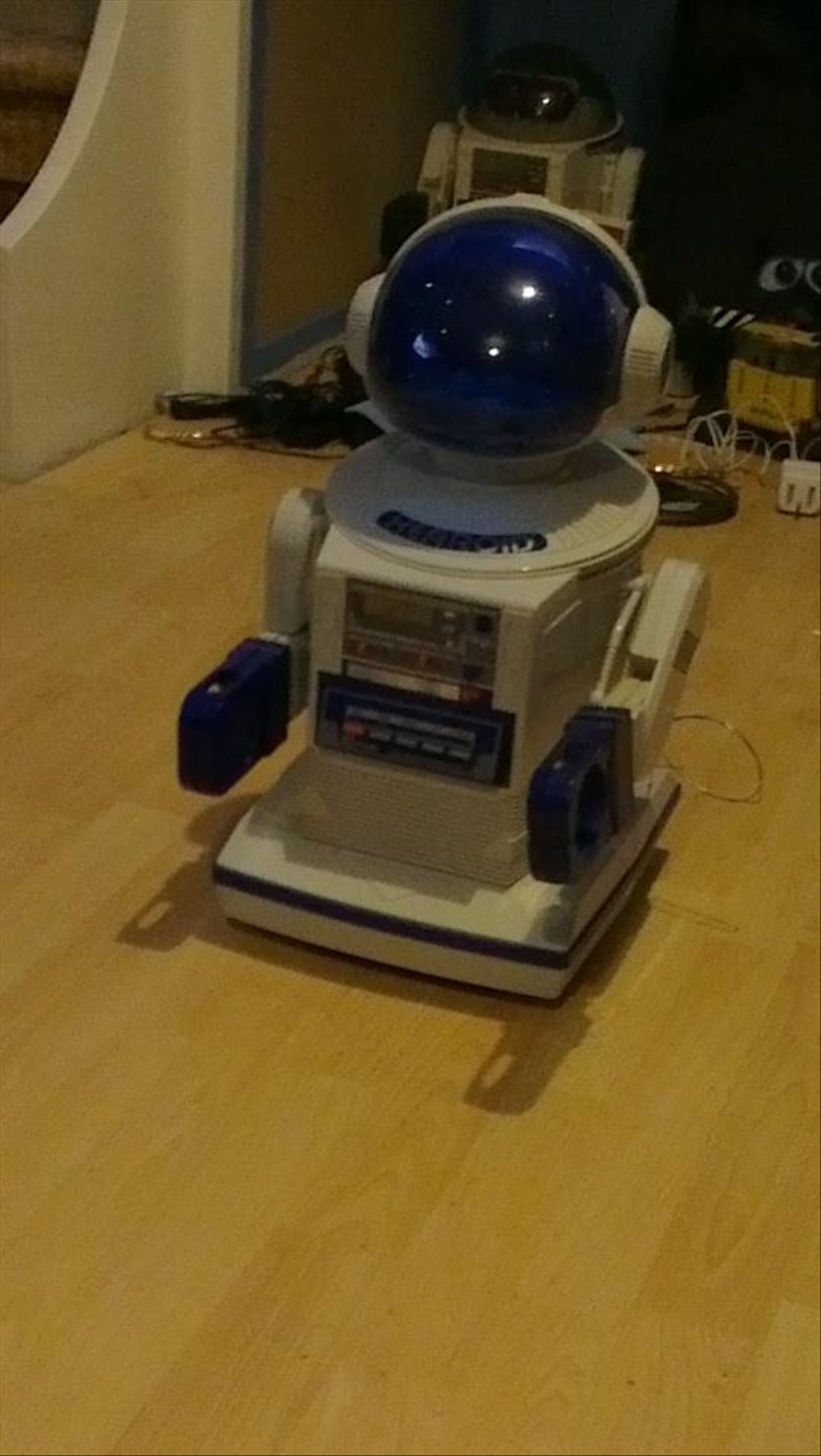
I won this robot on ebay weeks ago, for the past 2 weeks he has been waiting for me to collect him...
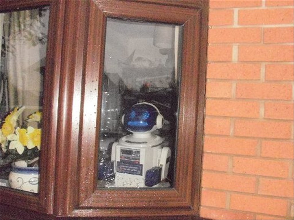
Today was the day, a road trip to pick him up and bring him back to his new home...
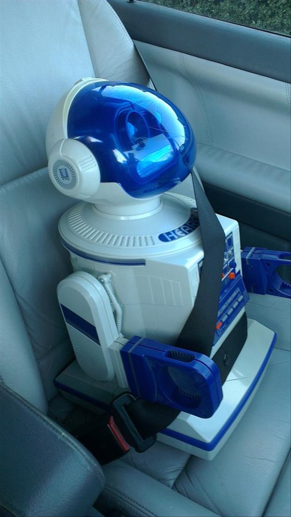
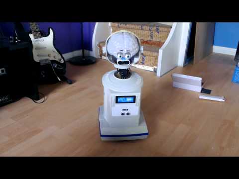
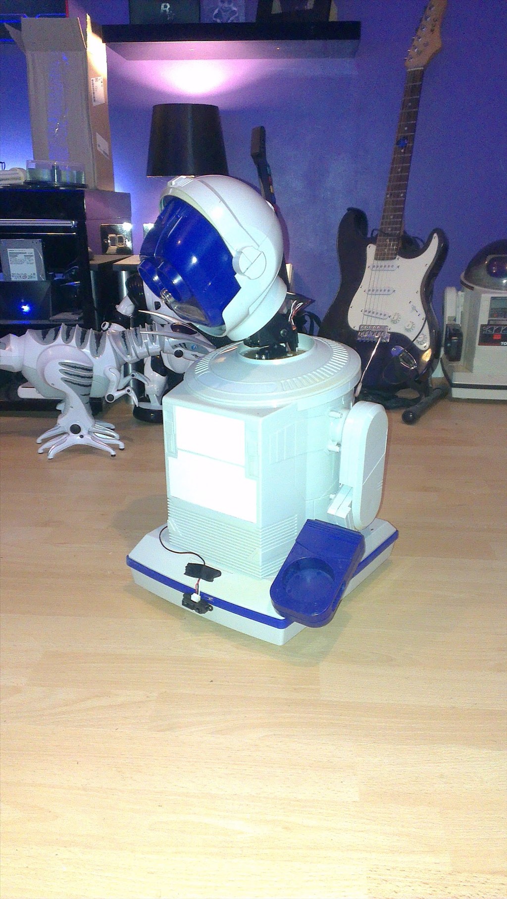
In his new home (with Omnibot and Wall-e in the background totally unaware they are next in line to be opened up)
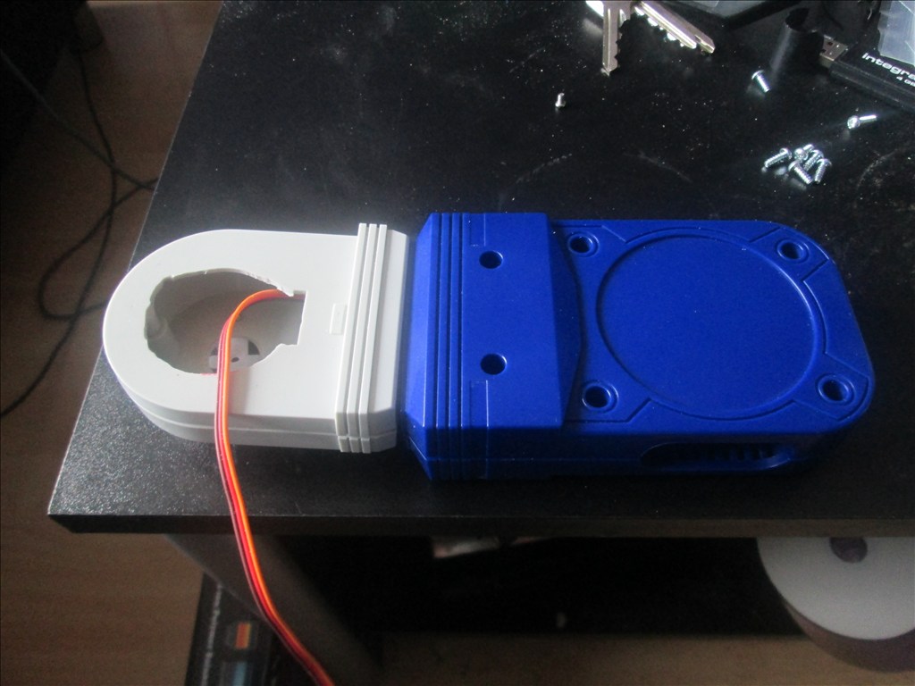
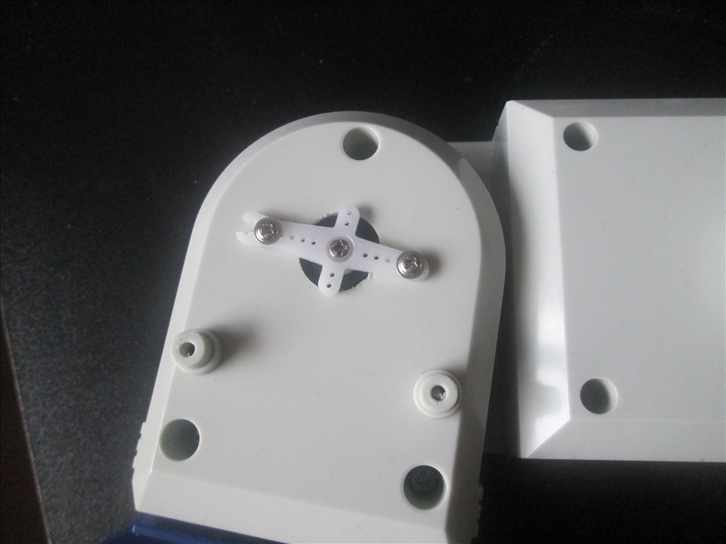
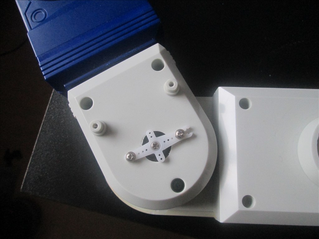
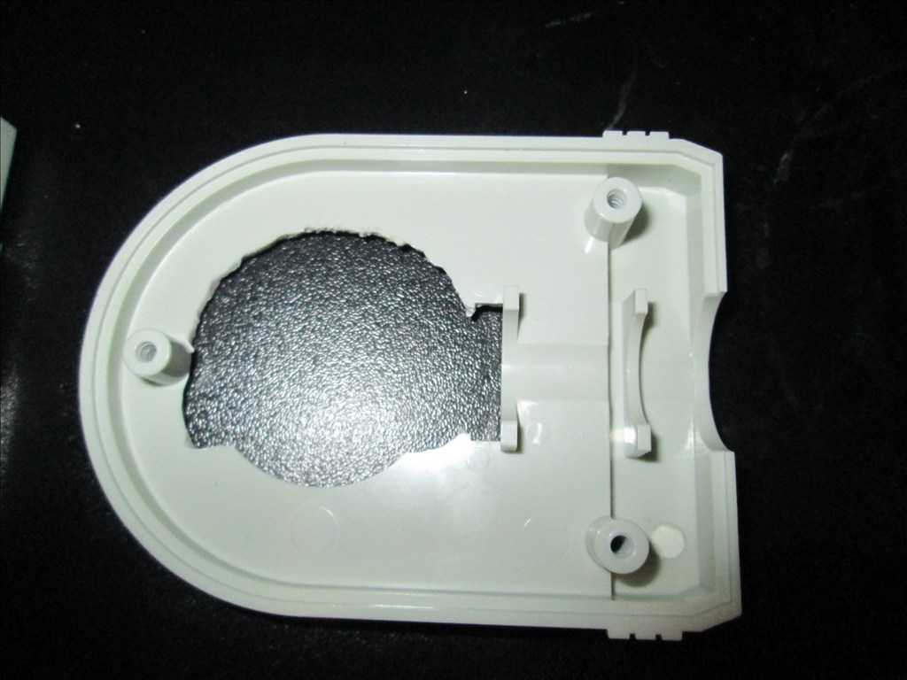
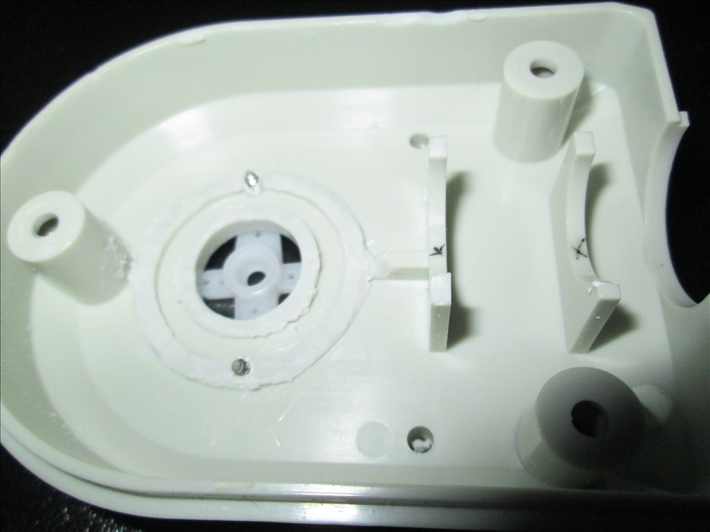
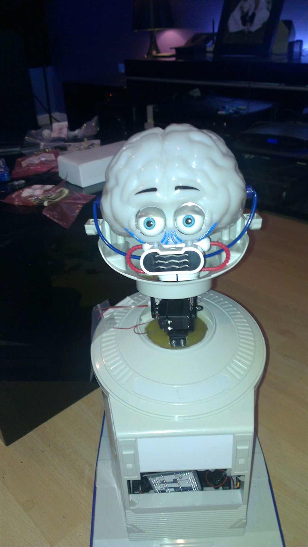
It wasn't long before this happened...
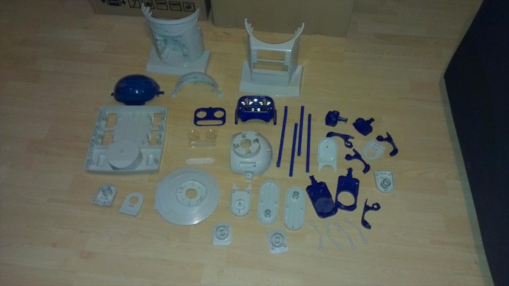
Now waiting to go in the dishwasher to get nice and clean.
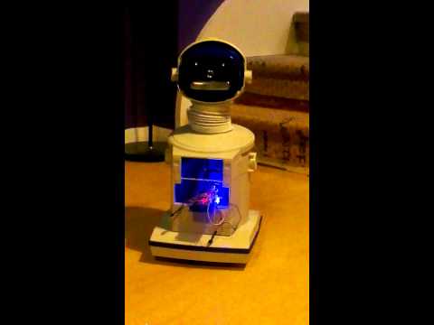
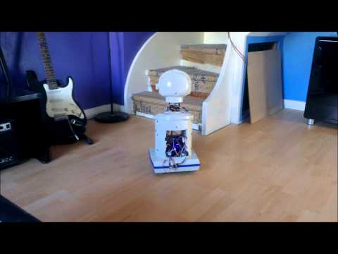
The plan is to make him autonomous, running 24/7 (except for when he knows to go charge himself up) but will also be adding in the various image tracking options.
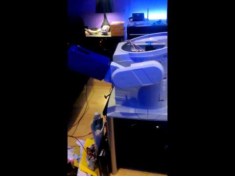
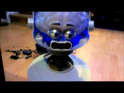
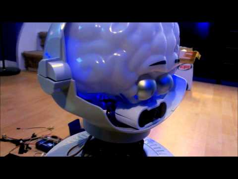
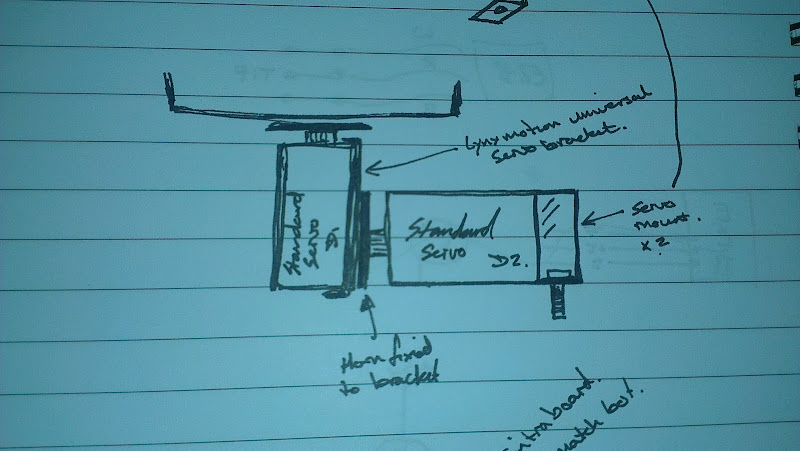
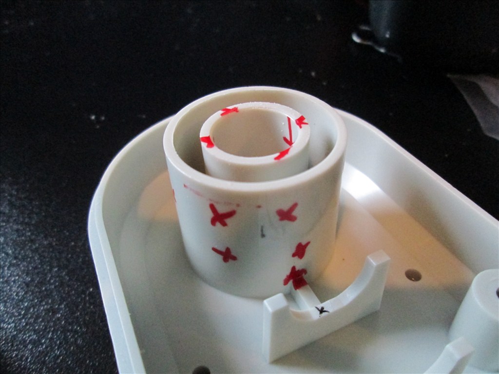
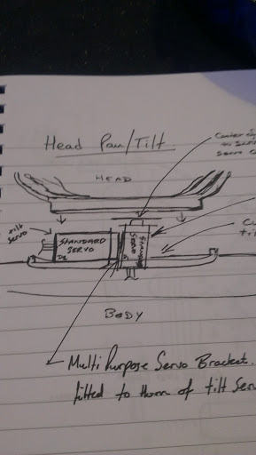
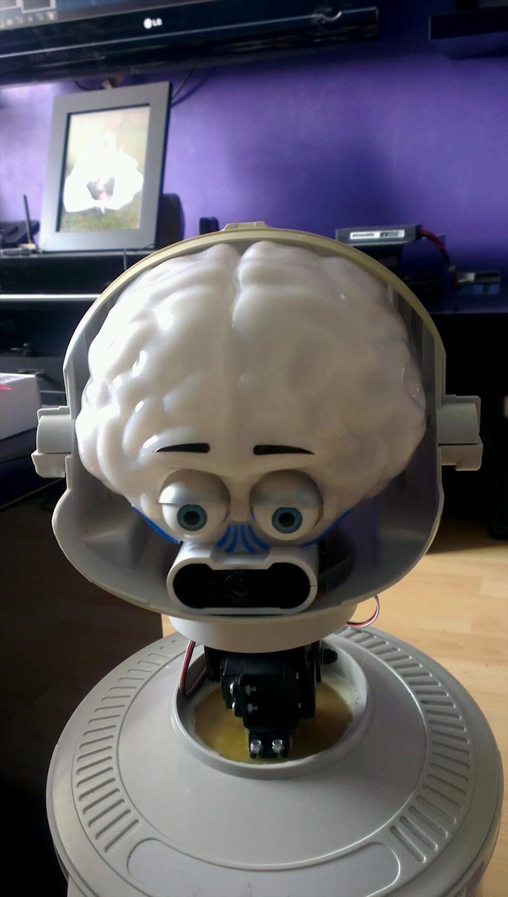
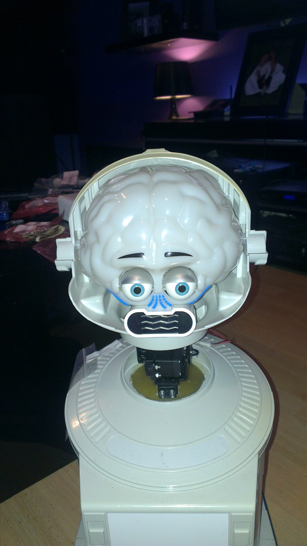
The only other slight modifications to be made to him are to convert the head to tilt & pan which will involve having to give him a small neck.
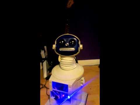
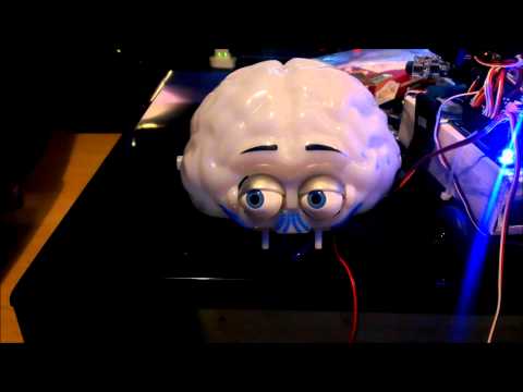
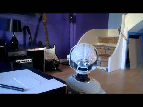
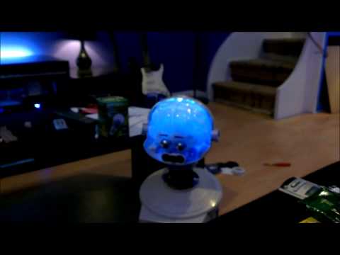
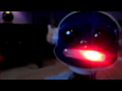
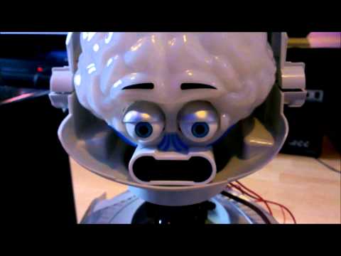
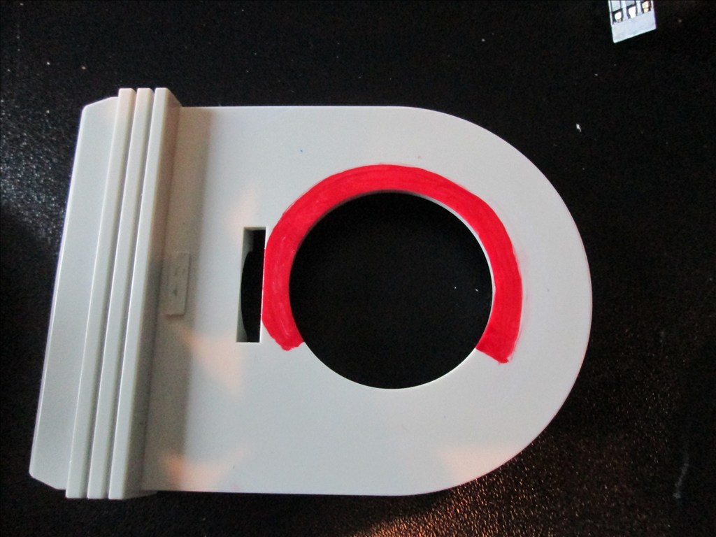
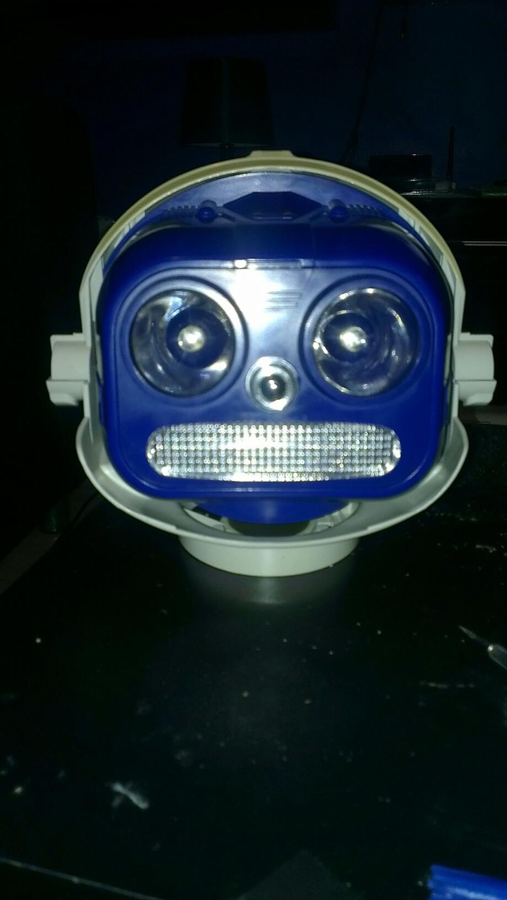
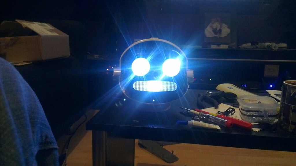
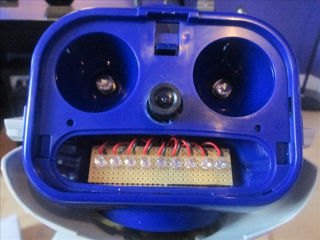
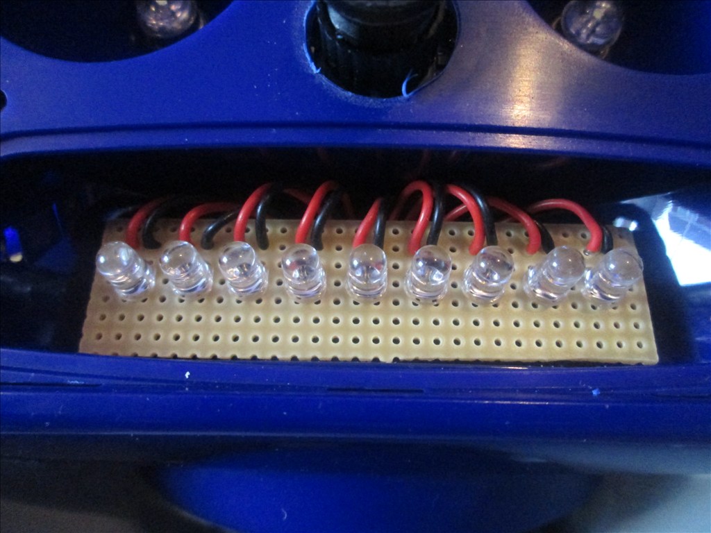
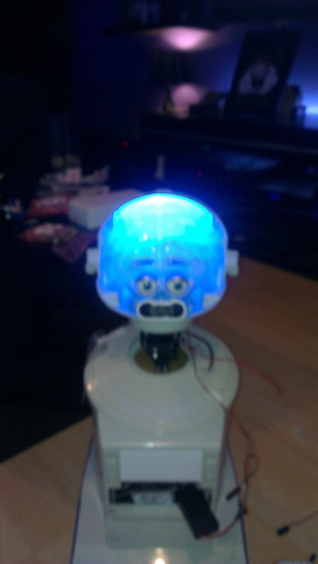
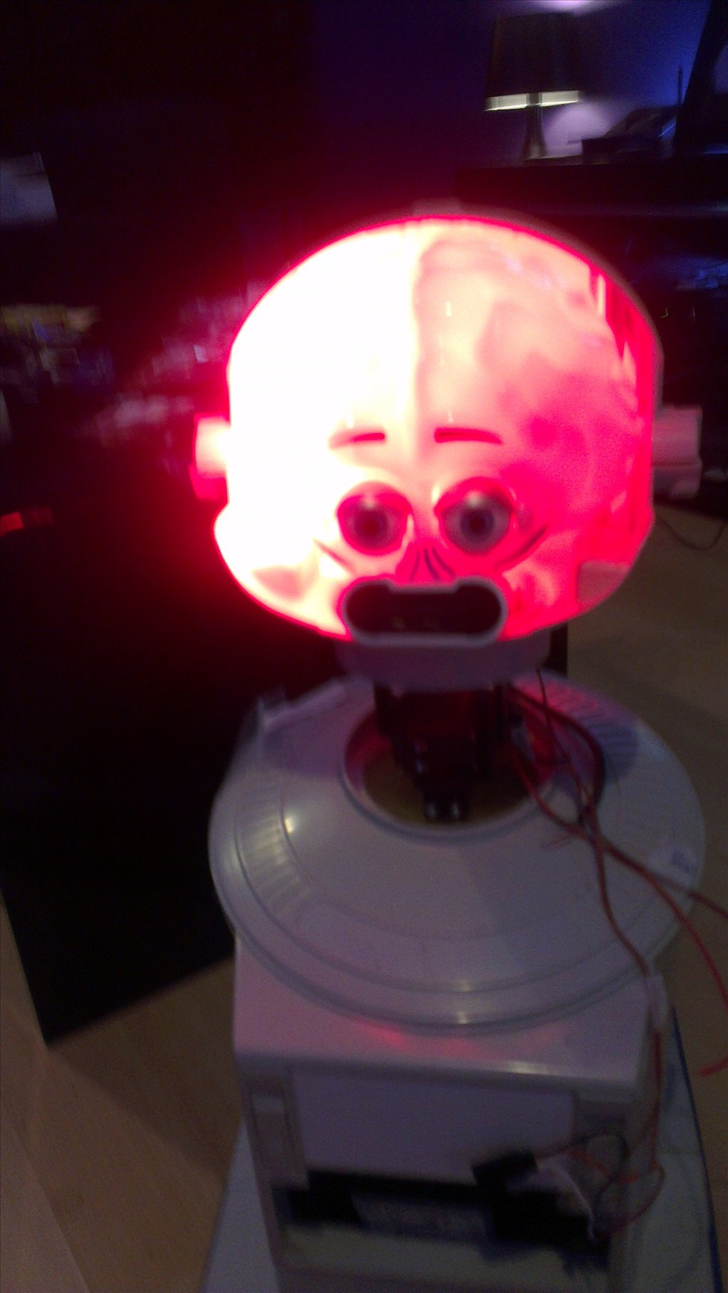
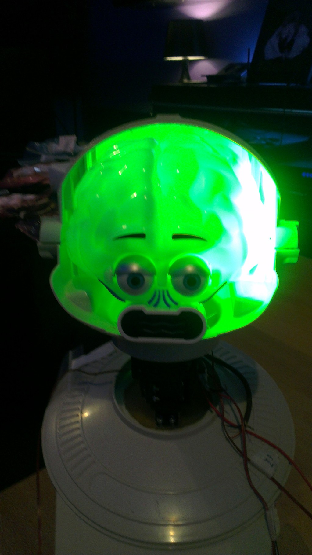
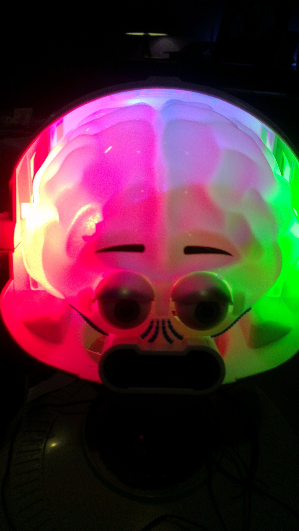
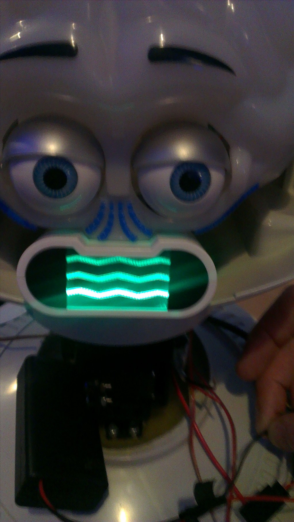
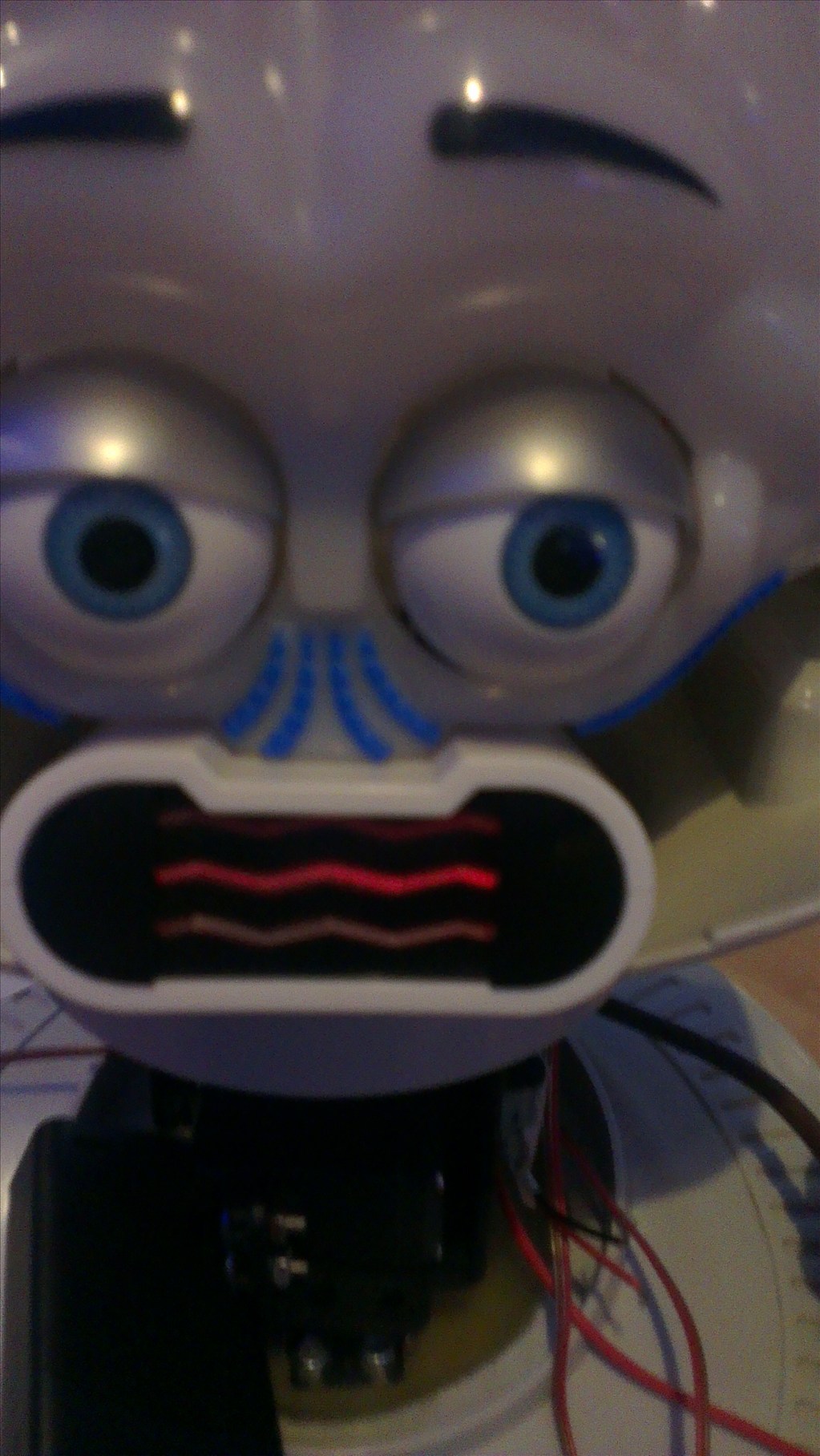
The head will include the camera. I haven't yet decided to fit it in one of his eyes or to make it his nose. The issue to overcome with this is the blue tint on the bubble head. The mouth will have a light or some lights in which flicker when he speaks.
The arms will be given some life with servos at the shoulder joints and the elbows provided I can get them to fit in there nicely.
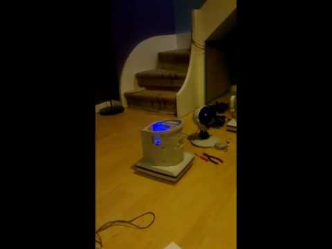
Ultrasonic sensor will be in his chest, probably on a servo to give a wider view.
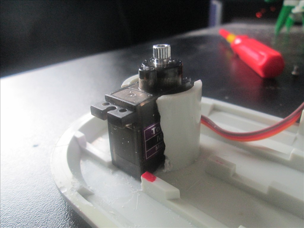
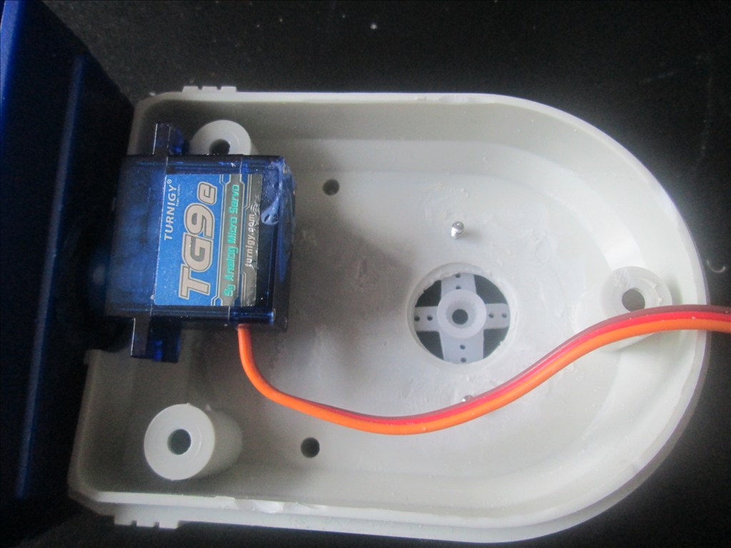
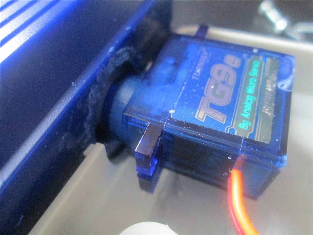
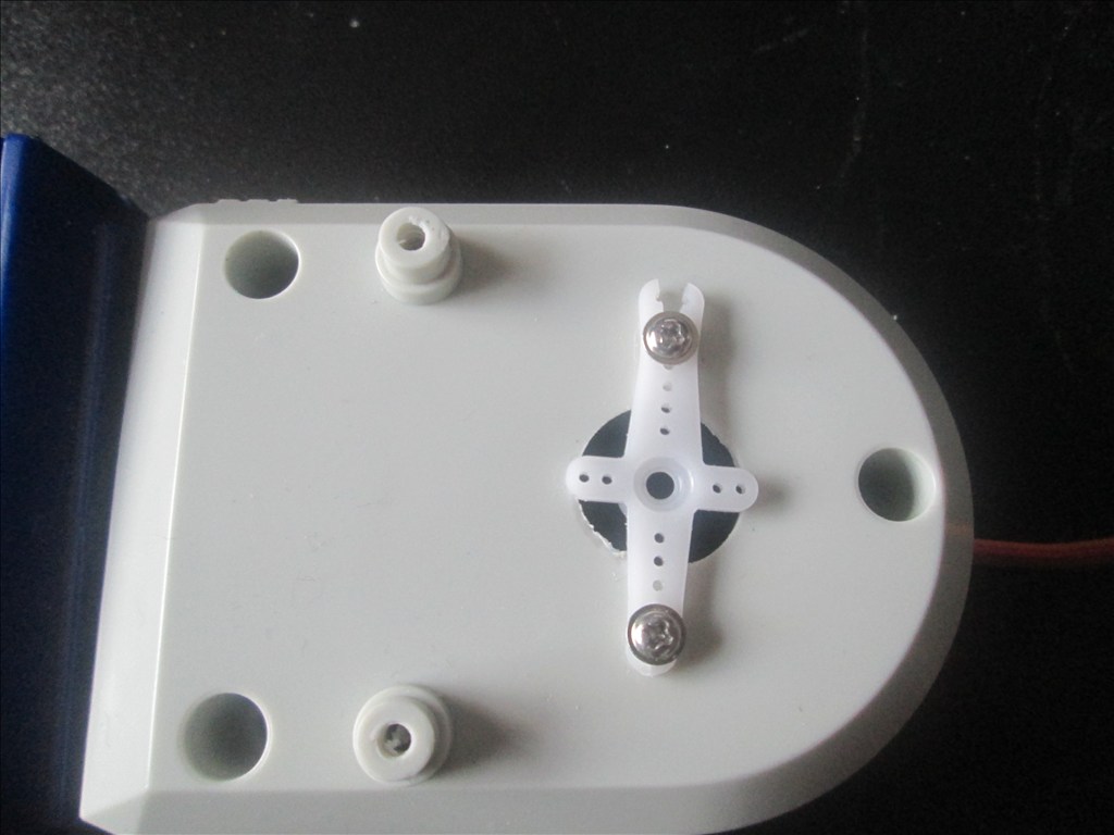
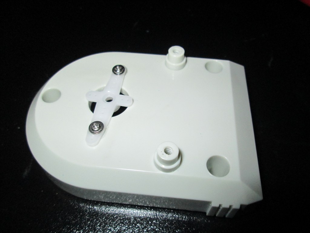
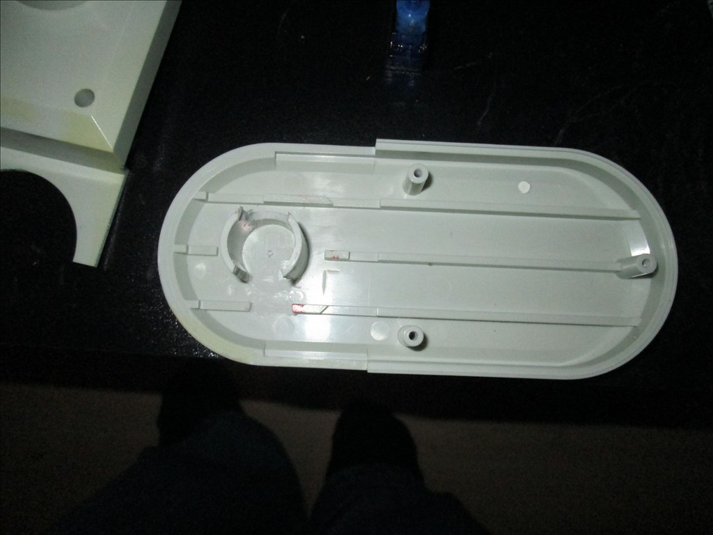
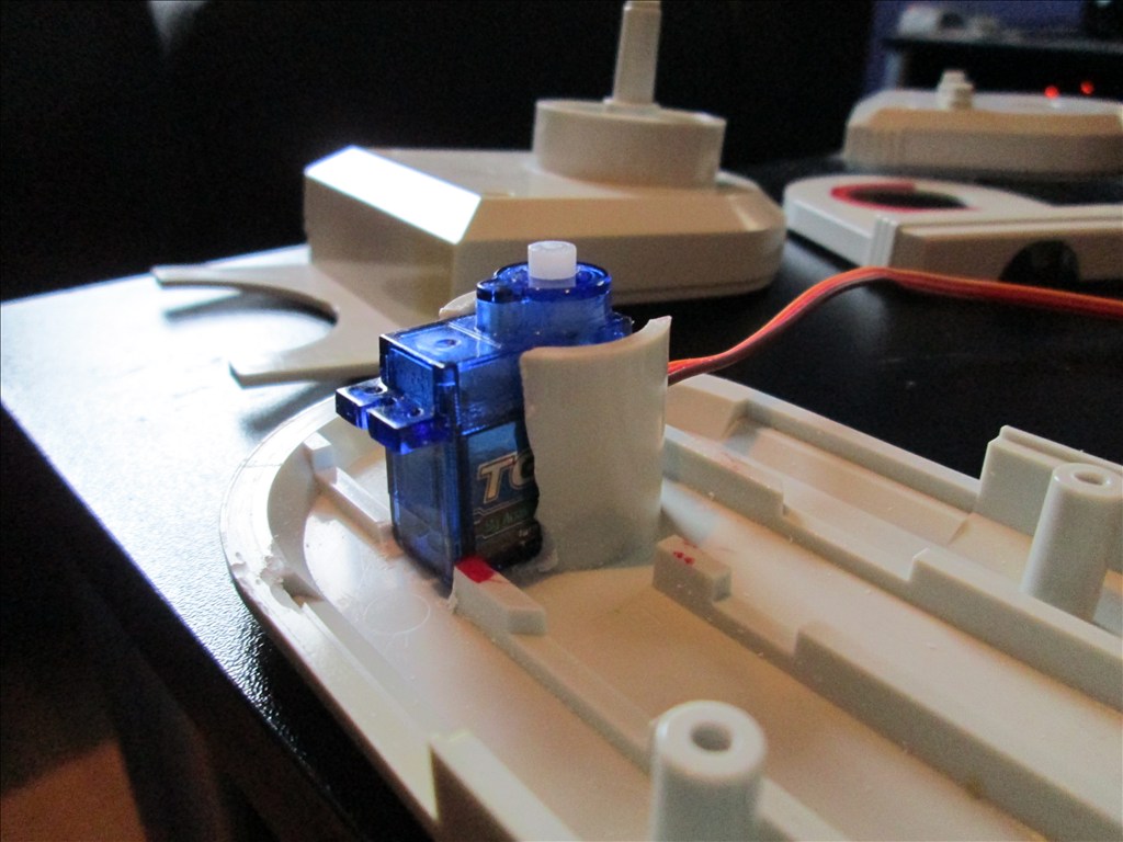
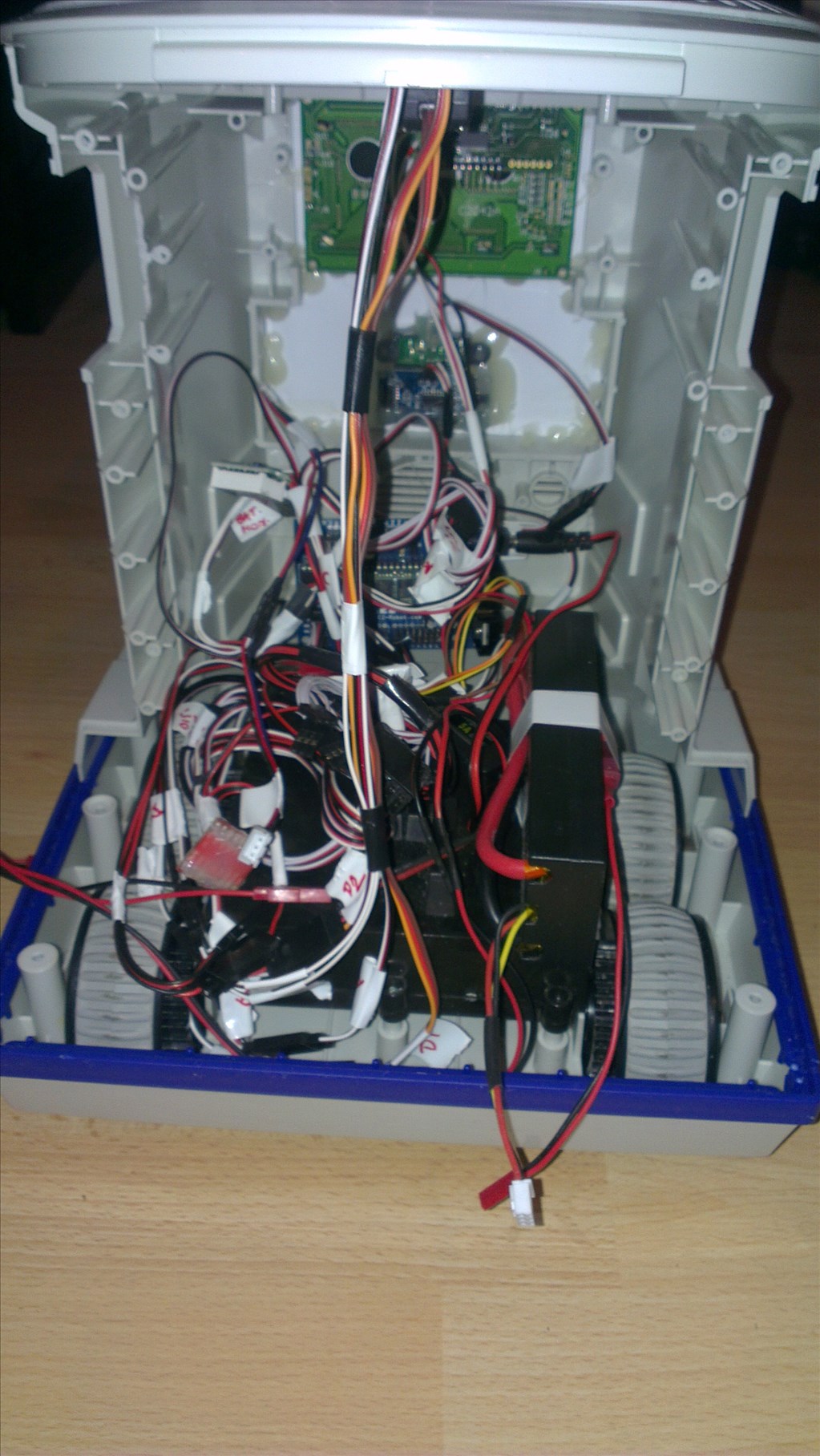
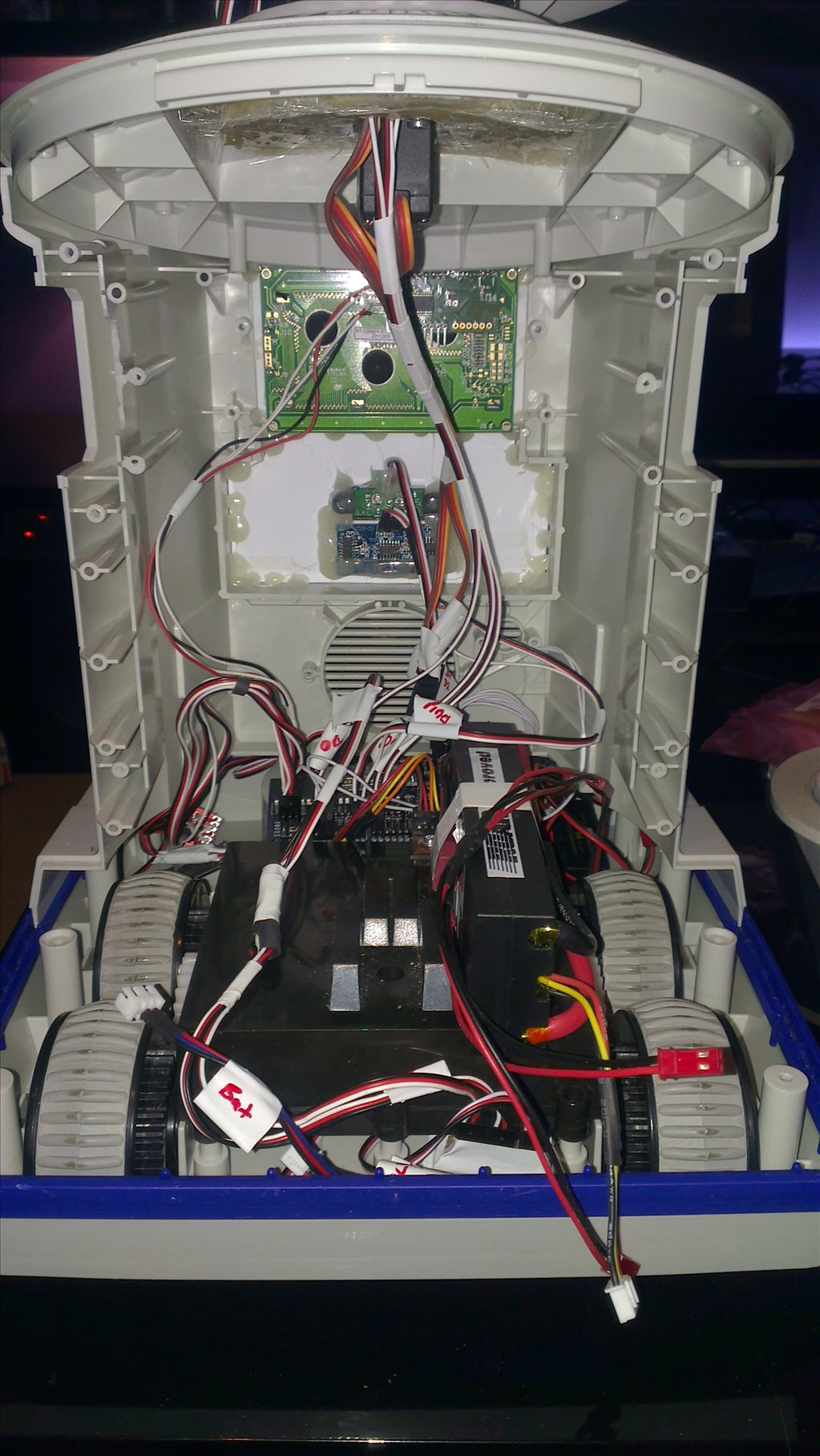
Original drive wheels and gearbox seem to be in very good shape so will plan to reuse those and just replace the existing motors for the modified servos if they can manage the task.
Speaker and microphone will be in the original positions - if it's not broke why fix it?
Not too big a project but enough to give me a test, help me learn and bring an old robot back to life.
Discover more robots
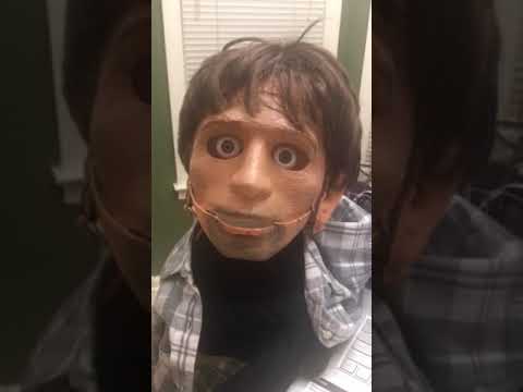
Ezang's Roman With New Head Movements And More...
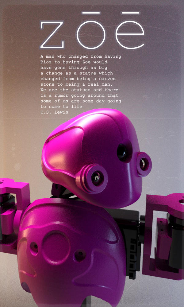
Mickey666maus's ZOE : A Machine That Resembles A Living...

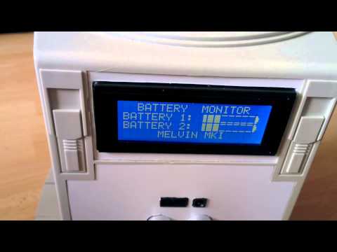
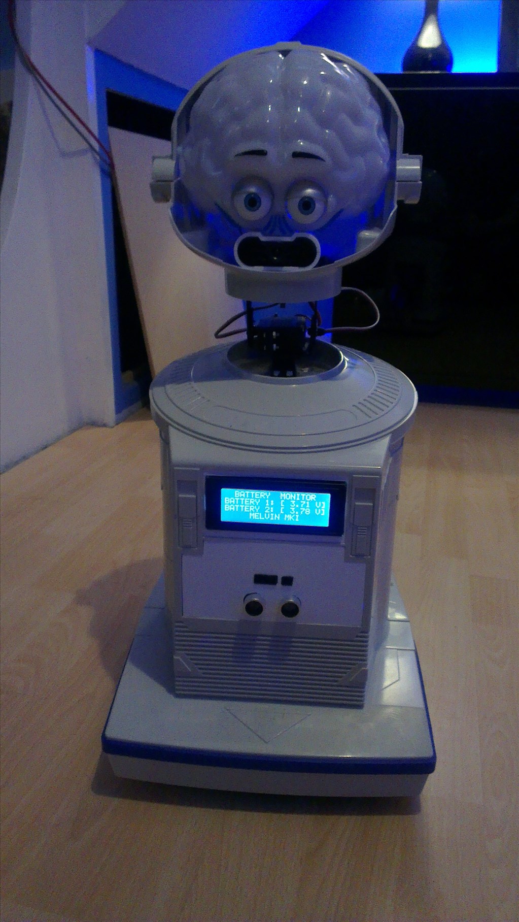
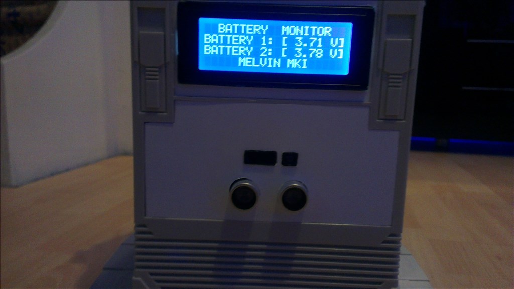
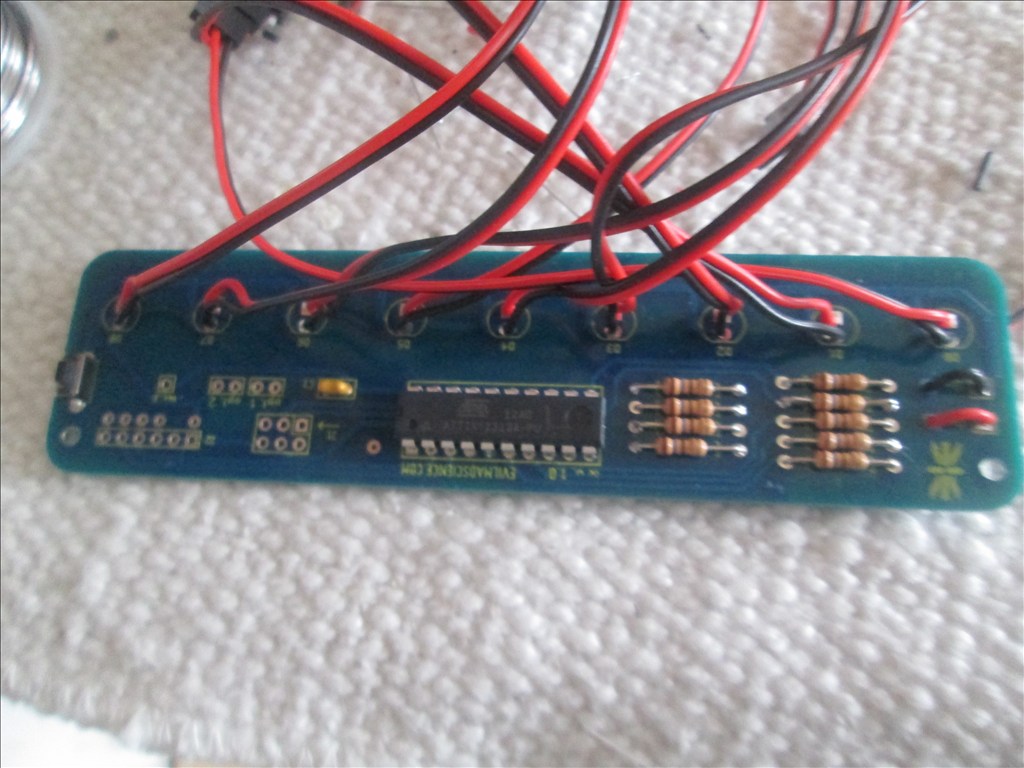
Rich, I noticed that you do not have a contrast preset pot on your LCD05, the pads are there to add one and this lets you adjust the contrast and viewing angle of the display. I can post more info on this if you need it?
I adjusted the contrast through the I2CWrite() command (I think it was 30 or 31, one does backlight brightness the other contrast). Unless the pot would do something different?
@rich have you measured the current the servos draw. Hook one up and meter it , tell the servo to turn and apply resistance to the horn , not enough to hold it in place but enough that the servo much make an effort to move your finger. I'm betting they can Pull a lot of current when a load is applied. Imagine if they pulled 5amps each just for a moment ..... I can imagine that could do it.
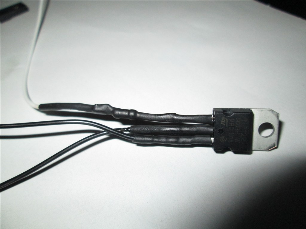
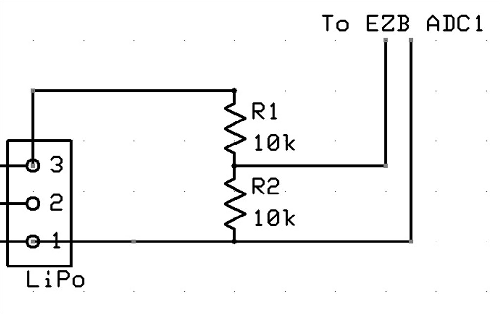
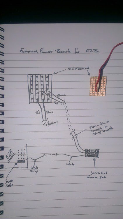
I plan to measure the current at some point, although not an issue now they have their own 5A 6V supply but I will need to know for when I put the arms on. I'm tempted to go overkill and add in a couple more 6V 5A voltage regulators, one for each arm.
I would give at least 2.5amp ceiling for each servo. You could just parallel 4 regulators though. I checked specs for my hitec servos of similar ratings and they indicate they can draw 5 amps
So to parallel 2 of them, and it's a bit of a dumb question that I think I know the answer to but just want confirmation, I would just connect the two +V in together and the two +V outs together, which would give a combined max current?
I.e. 2 x 5A regulators, +Vin both connect to the battery, +Vout connect to the servo or circuit, it would allow 10A max current?
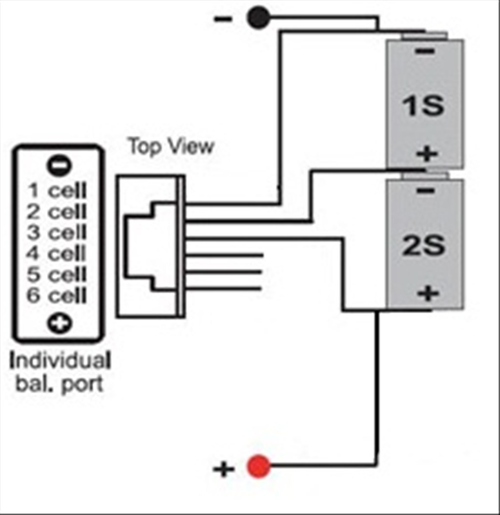
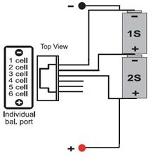
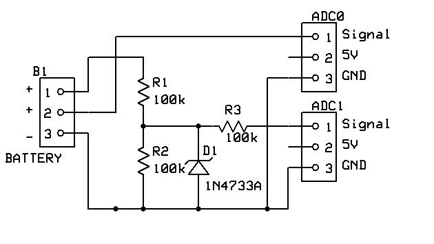
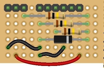
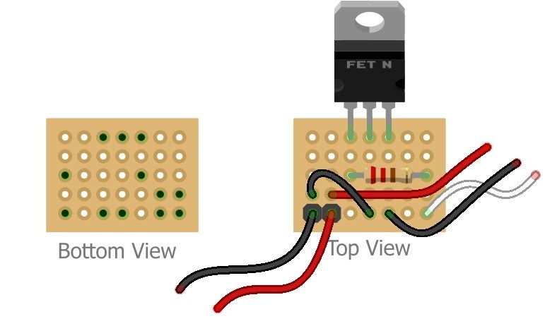
Yes , parallel them and they share the load. here's a bad drawing I googled for anyone silently watching
As I thought, thanks.