
-636348381130562972.jpg)
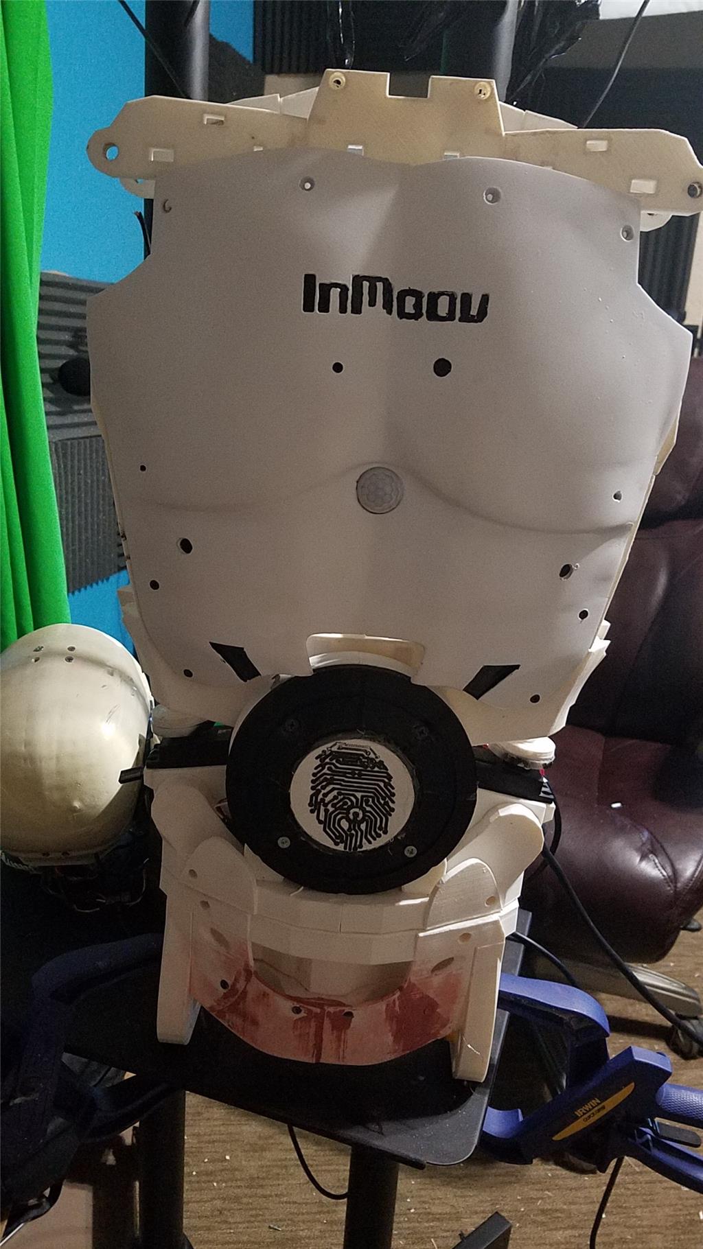
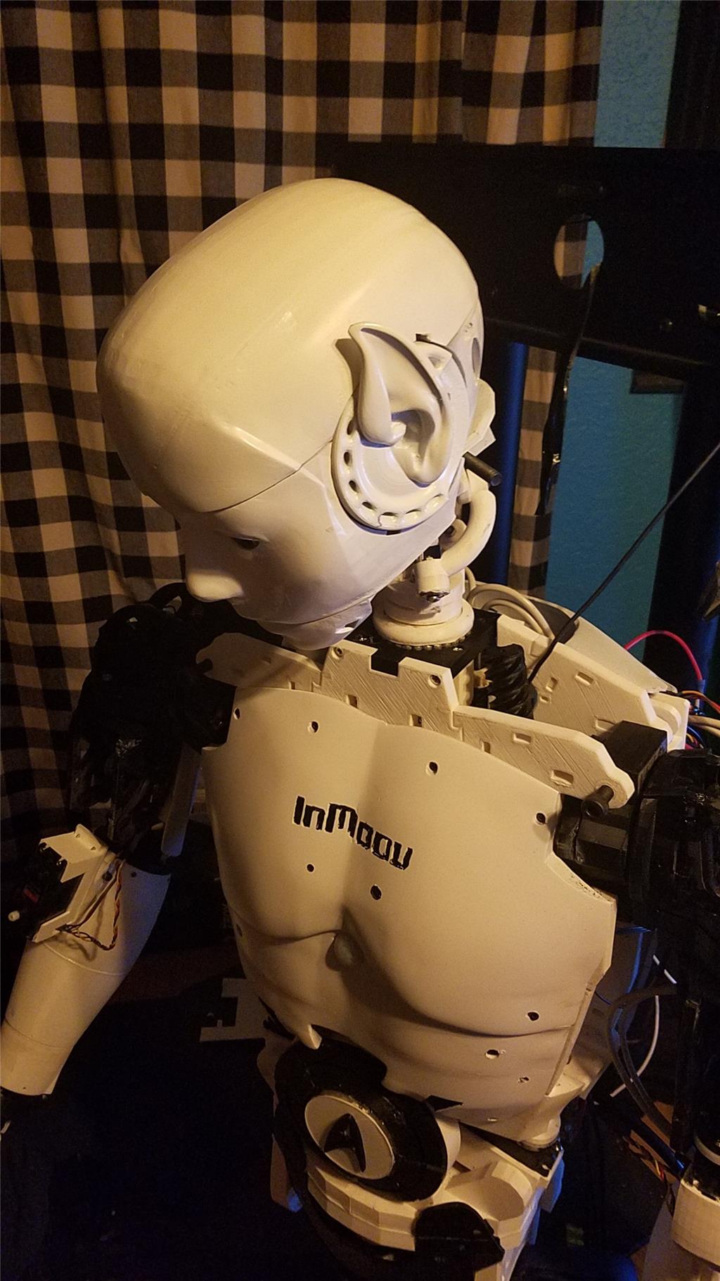


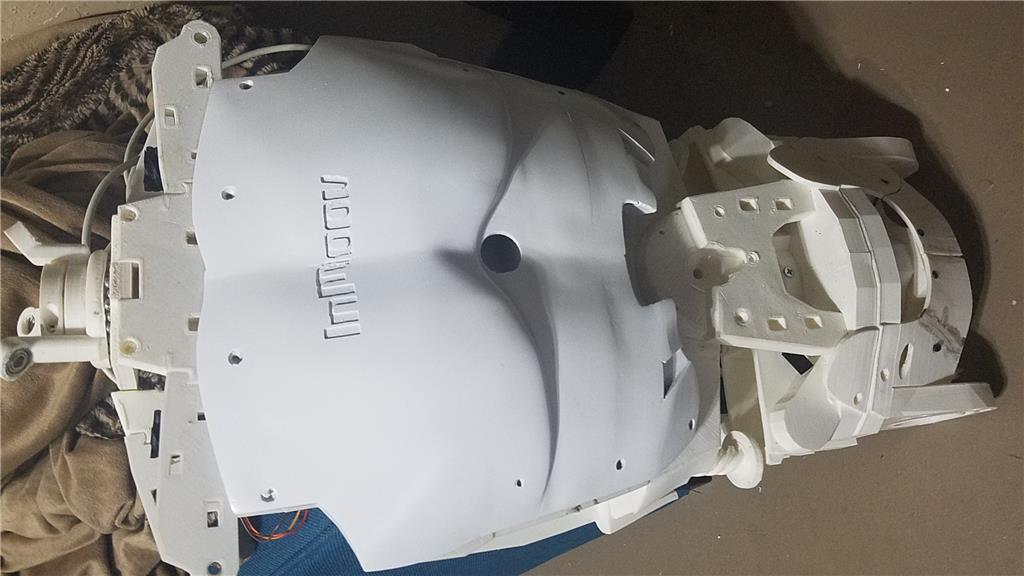
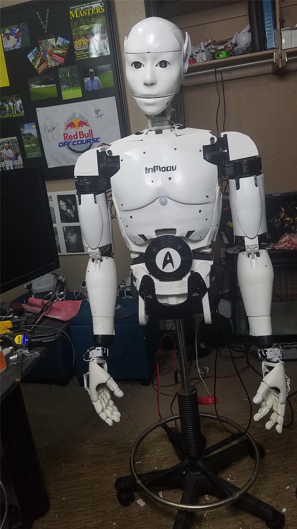
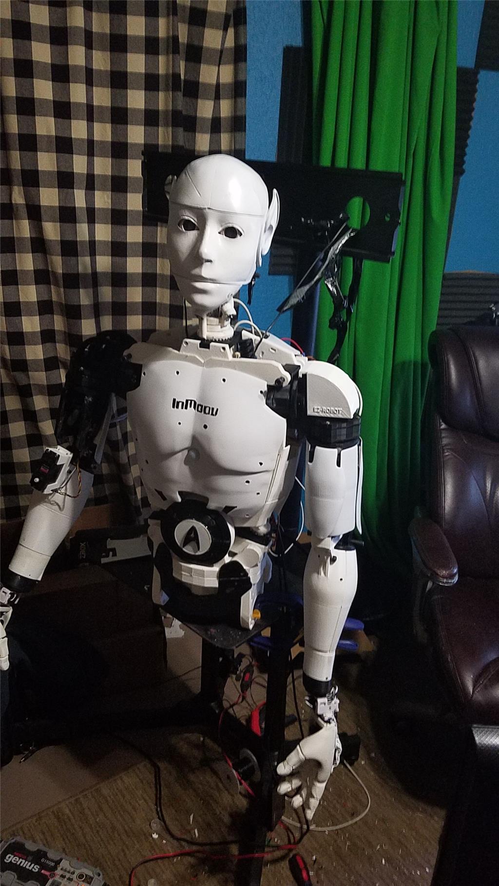
I have decided to start my InMoov project. I think I will call him Spock out of respect to Leonard Nimoy who passed away on the day that I started this project.
I am editing this post so as not to confuse people with the current configuration. I continue to update this post with the latest photos. If you are reading this for the first time, don't be confused. There have been a lot of changes to the InMoov over the past couple of years including starting over.
https://synthiam.com/Community/Questions/7398&page=21 Post 203 starts the rebuild of the InMoov.
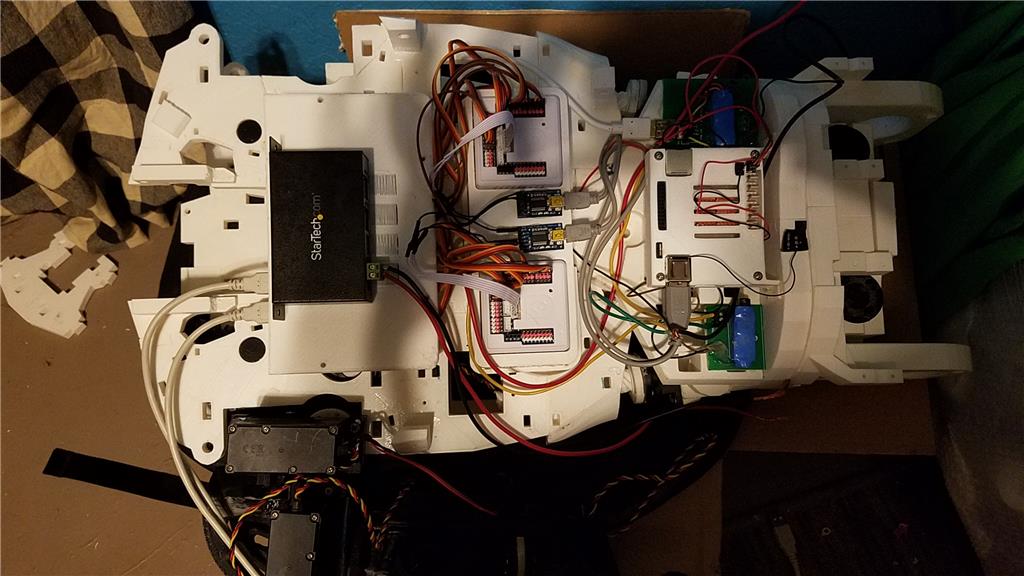
I have decided to use an onboard computer. I chose the Latte Panda due to it having an onboard arduino Leonardo and also because it uses little power.
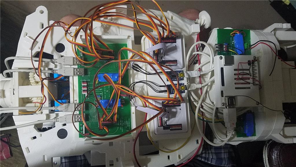
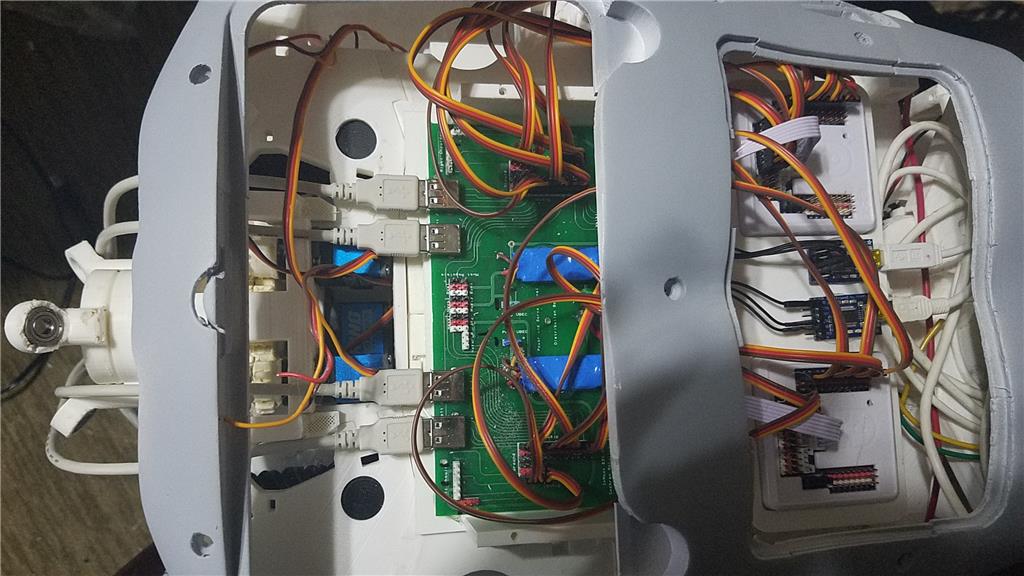
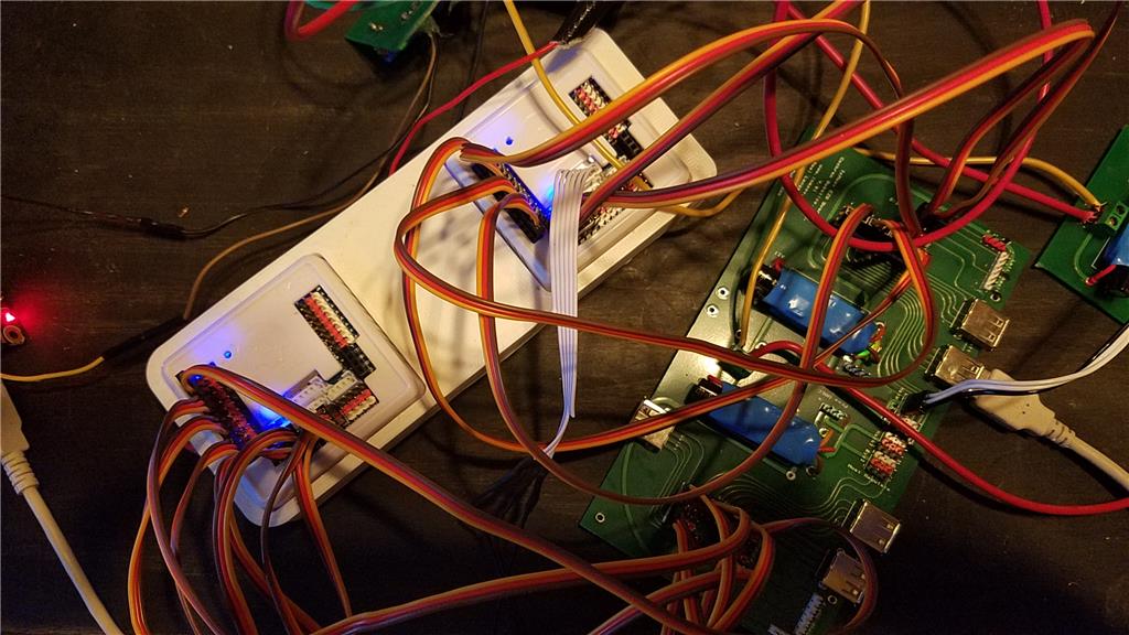
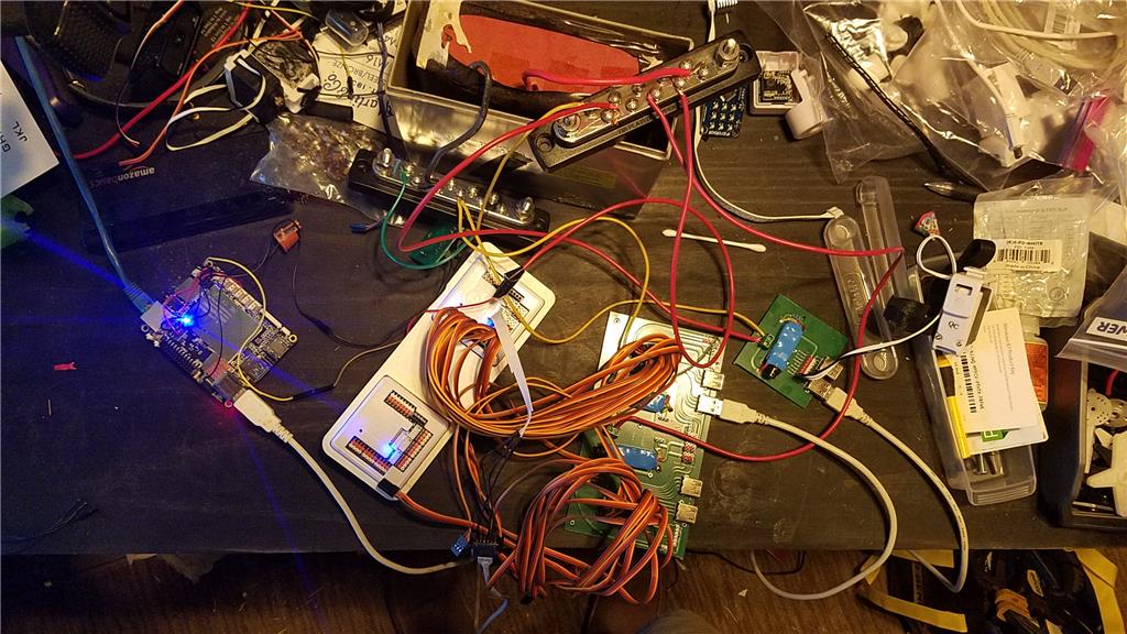
I used 2 EZ-B controllers connected via the camera port to Adafruit FTDI friend boards. This allows the Latte Panda to have a non-wifi dependent connection to the EZ-B's. I use a powered USB hub connected to the USB3 port on the Latte Panda to attach other items.
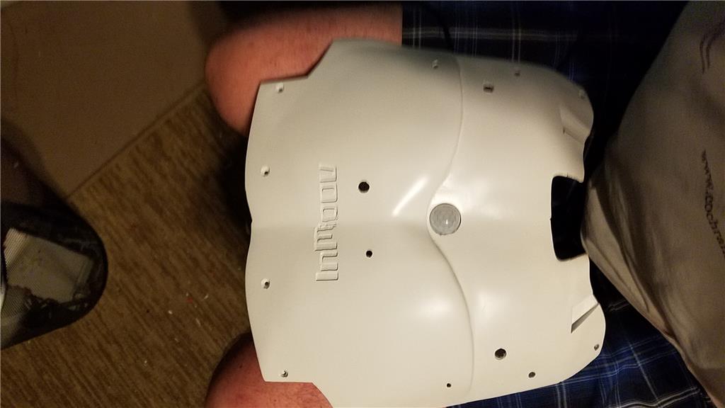
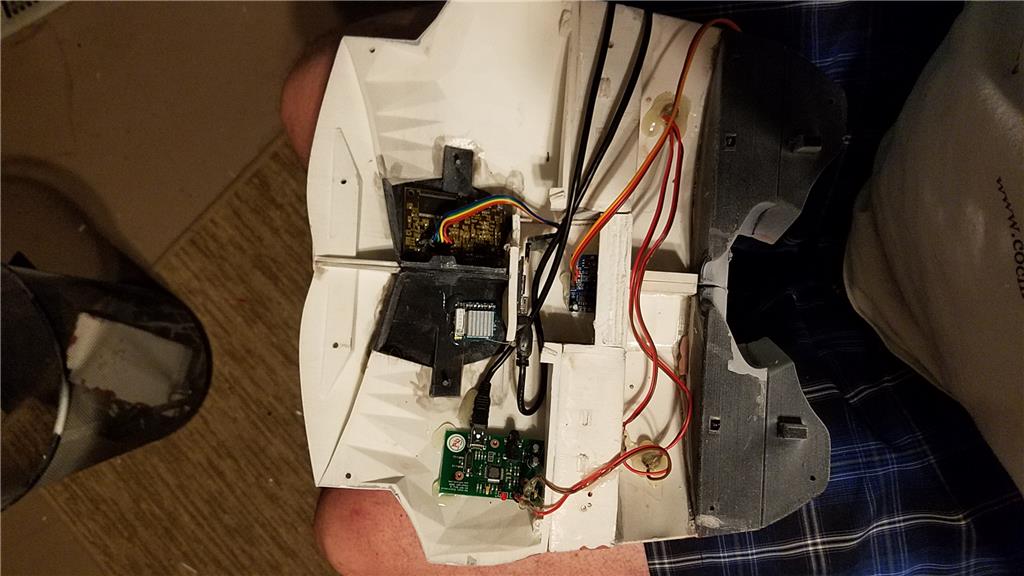
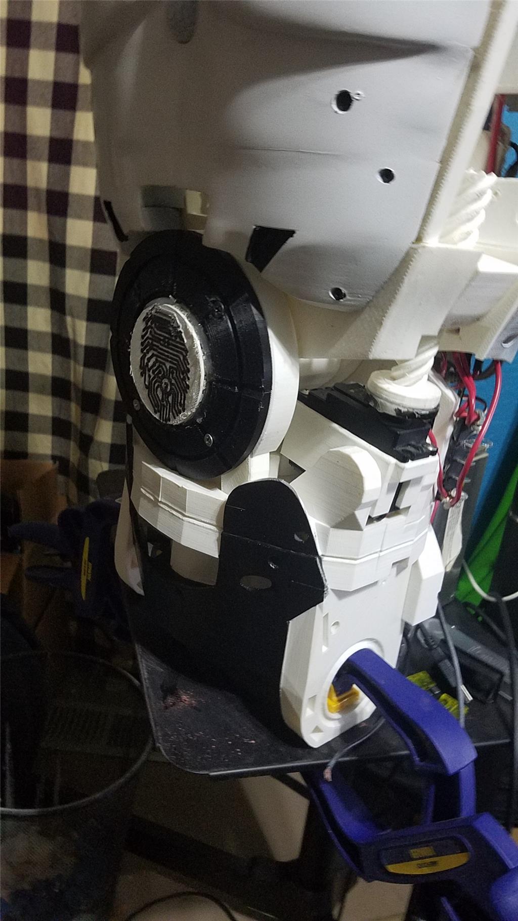
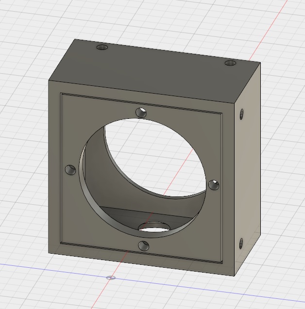
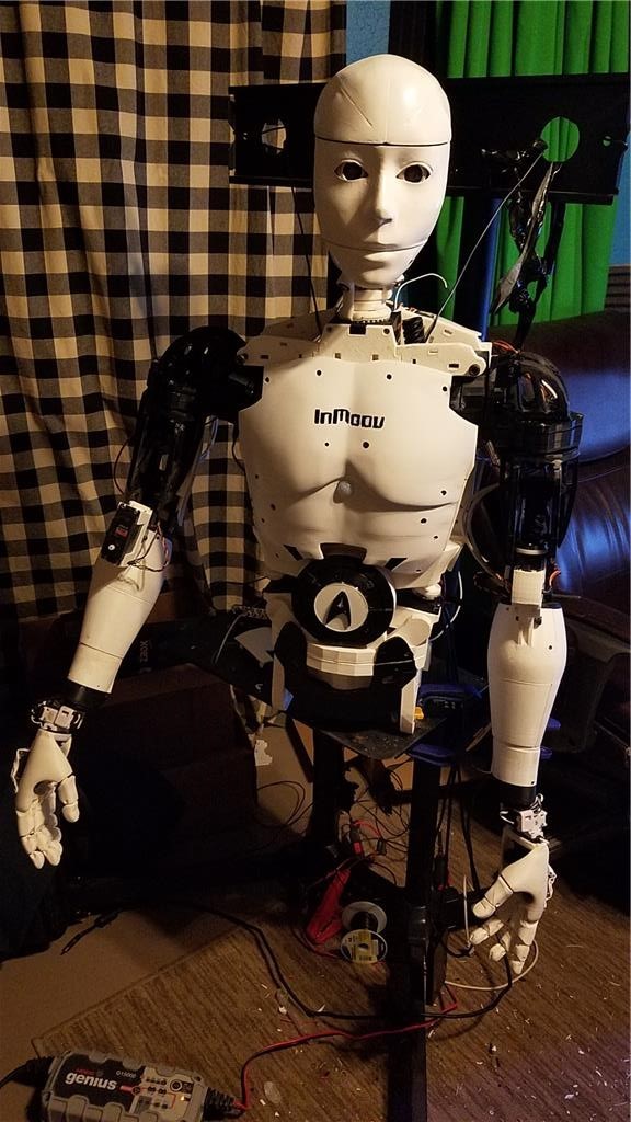
The Omron HVC-P is used to identify people, emotions, human bodies, hands, age and gender. It is attached to the Latte Panda via an FTDI friend which is then connected to the powered USB hub. It is mounted in the chest of the InMoov. I also use a 3 element microphone which is a MXL AC-404 microphone. It is disassembled and the board and microphone elements are mounted in the chest of the InMoov. This mic board is connected to the Latte Panda via a usb cable which is attached to the powered USB hub. There is a USB camera in the eye of the InMoov which is connected to the Latte Panda via the powered USB hub.
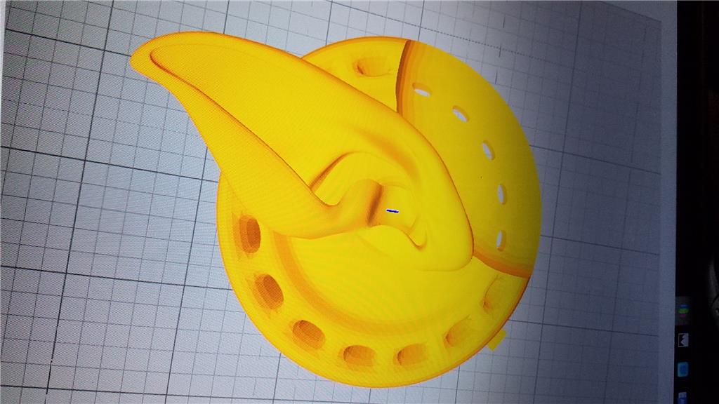
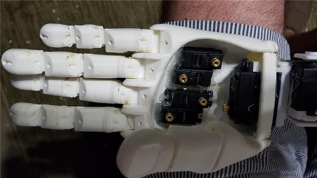
I chose to use the Flexy hand with the InMoov. The design is far more rugged than the original hand and works very well. There are 4 EZ-Robot Micro Servos in the palm of each hand which controls the main fingers. The thumb is controlled by an EZ-Robot HD servo. The wrist waves and uses an EZ-Robot HD servo to do this motion. I use the standard Rotational wrist.
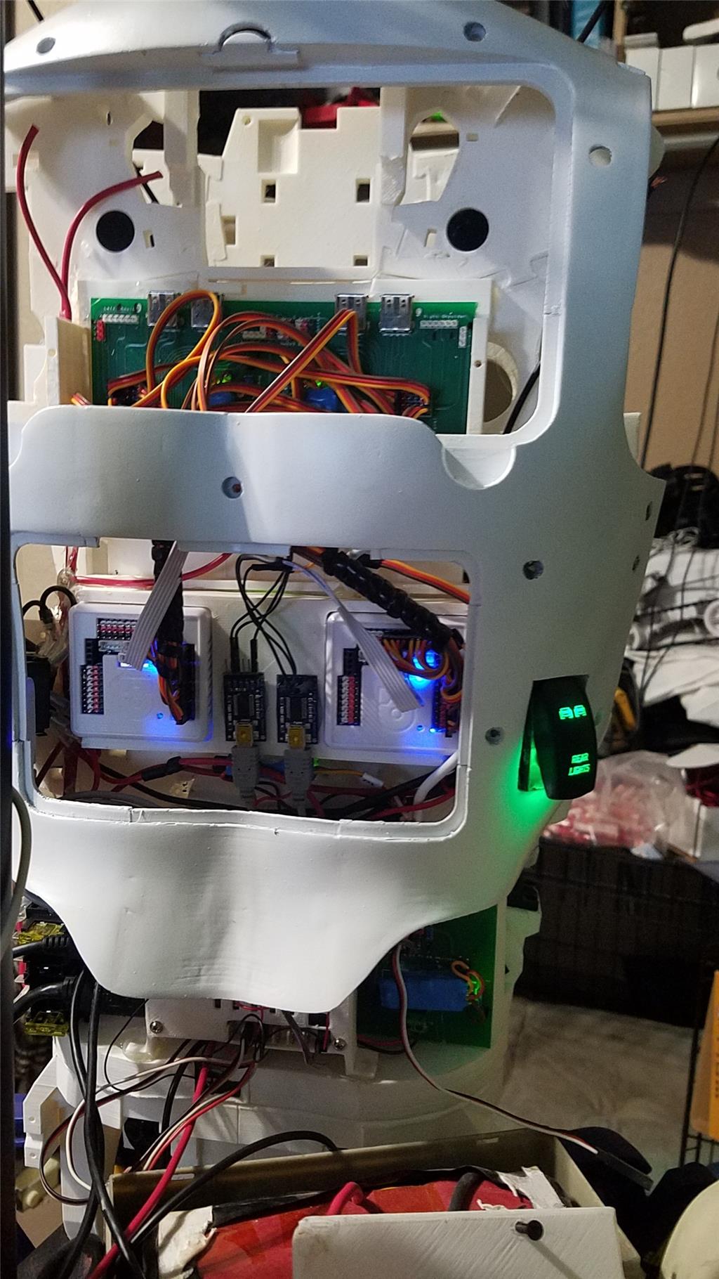
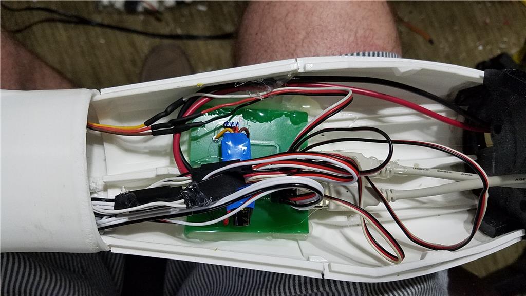
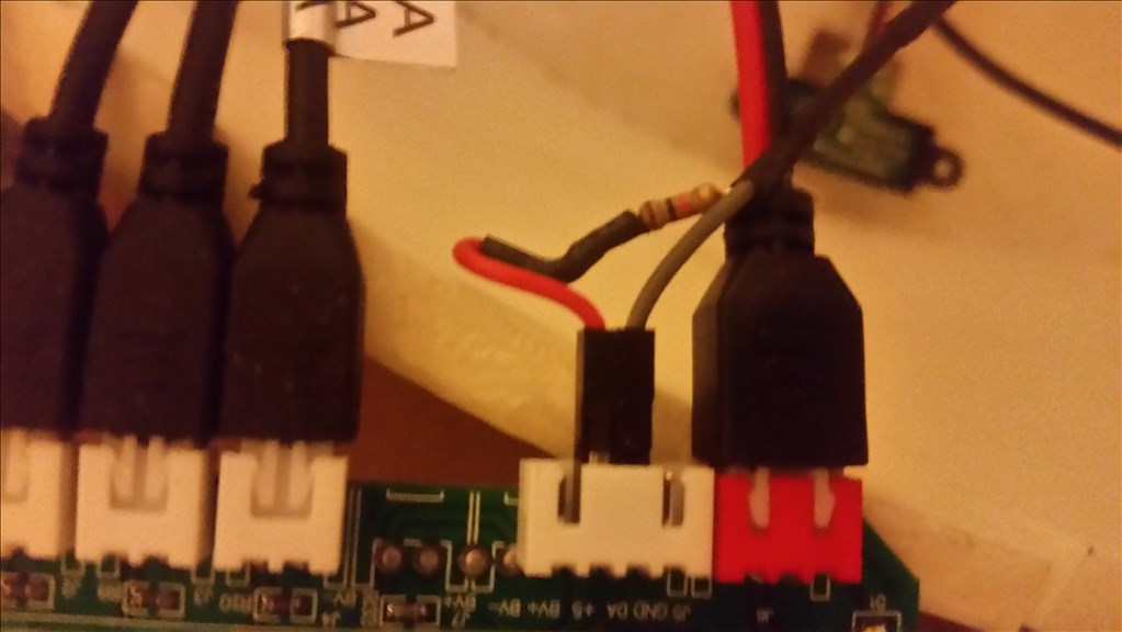
I have castle BEC's for power in the following locations set to the following voltages. Forearm's - 6.2 V - Controls fingers, wrist and elbows Custom power distribution board (2) set to 6.2 V controlling head, neck and Shoulder servos. EZ-B's - set to 6.1 V - it is mounted in the controller mounting plate and connects to the EZ-B fused power boards from a power base. Latte Panda - Set to 5.1 V and is mounted to the EZ-B controller mounting plate. Waist - set to 6.2 V and is mounted in the lower right side of the back. This provides power to the lean and pivot waist motors..
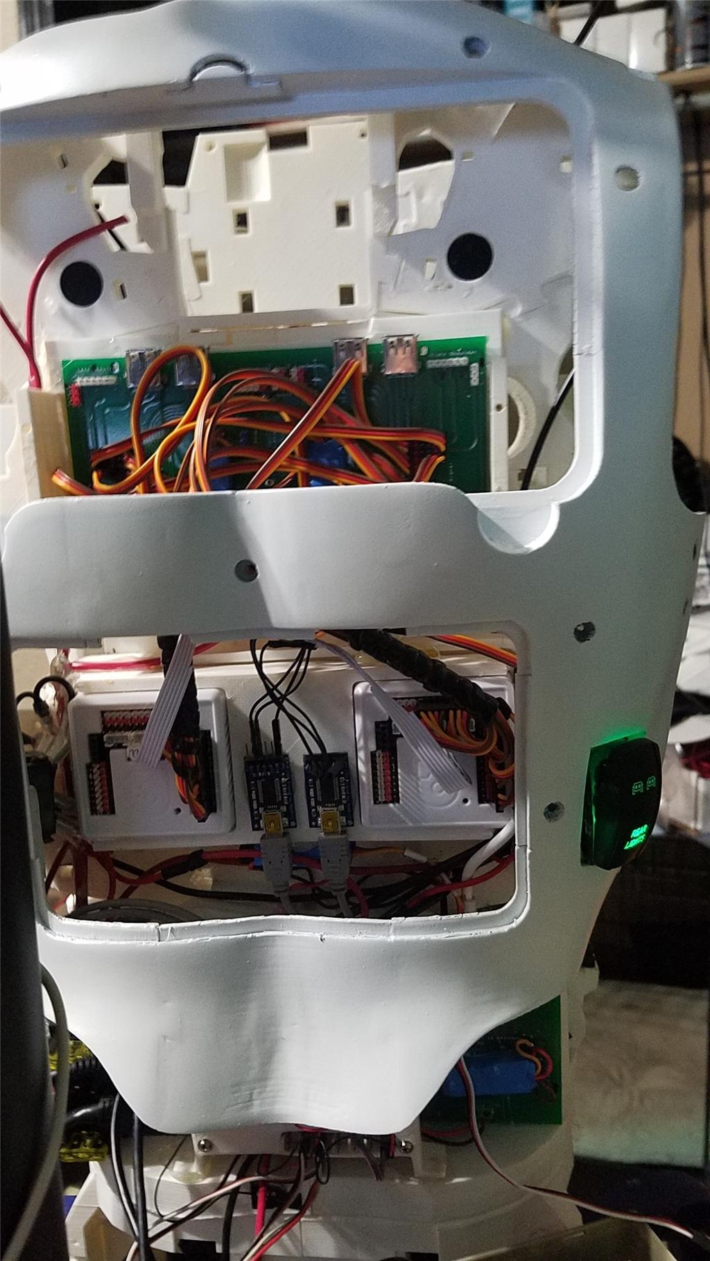
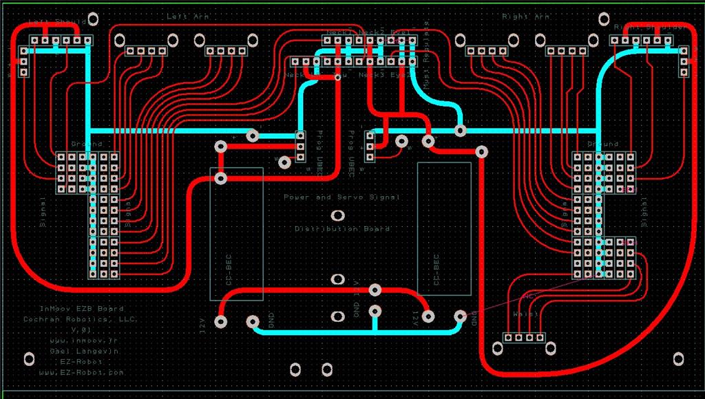
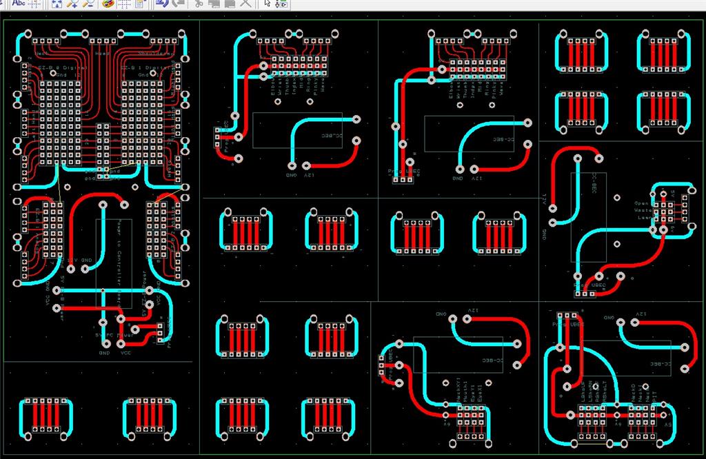
There are some custom power and signal distribution boards. These are in the forearms, lower back and in the upper back. The upper back or main board connects to these distribution points via USB cables to provide signal to the other boards for servos. The main board also has servo connector pins that are for the neck, head and shoulders. This allows the power to be distributed between multiple BEC's and also allows the servo signal cables to be shorter and more protected via the USB cables.
For power I use a LiFePo4 battery that is rated at 30 amps. It has the balanced charging circuit built into the battery and also has a low voltage shutoff built into the battery. This protects the battery and allows the battery to be charged with standard car chargers.
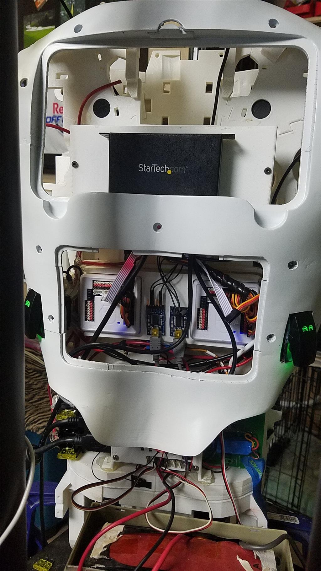
I put switches on the back on the InMoov which are rated at 20 amps at 12 volts. These are rocker switches that allow the user to pretty much slap the switch to turn it off. There are two of these switches. The servos for the elbows and fingers are on one switch. The latte panda, neck, shoulders, EZ-B's, waist motors and some lighting is on the other switch.
I also added a fuse block. This allows 20 amp fuses to be put in line to help protect things. The switches above drive the fuses for each of of the motors listed in that section.
-636348716348649435.jpg)

Discover more robots

Steve's Elvis Gains An Extra Degree With Ez Robot Hdd....
-635396587467336392.jpg)
Robot's R3 Roomba Control Using 5 Volt Relays


Looking verry good, I lyke the stomac color mix.
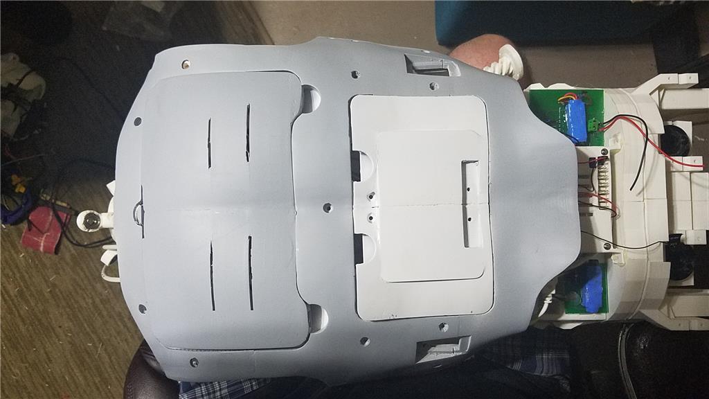
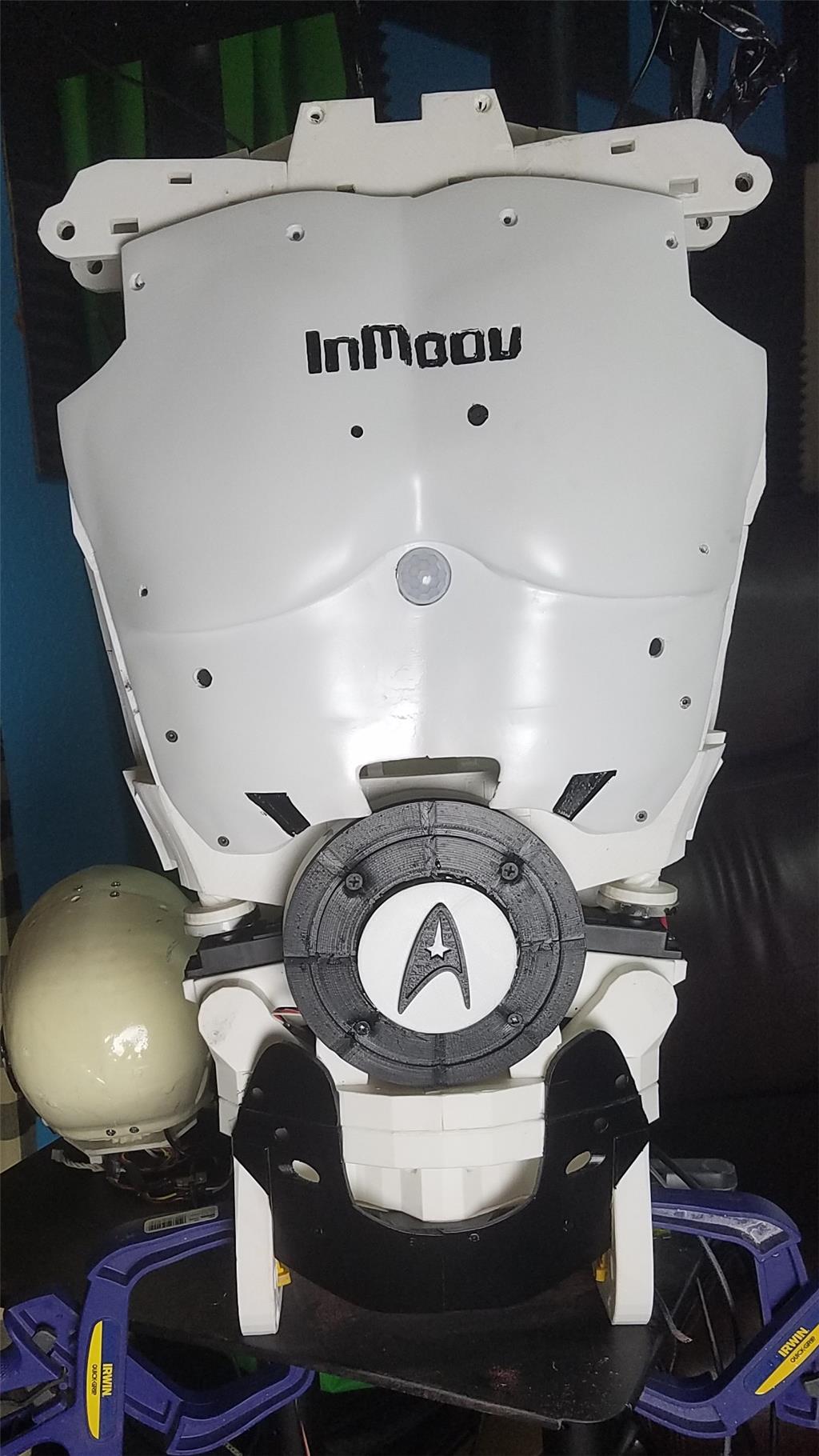
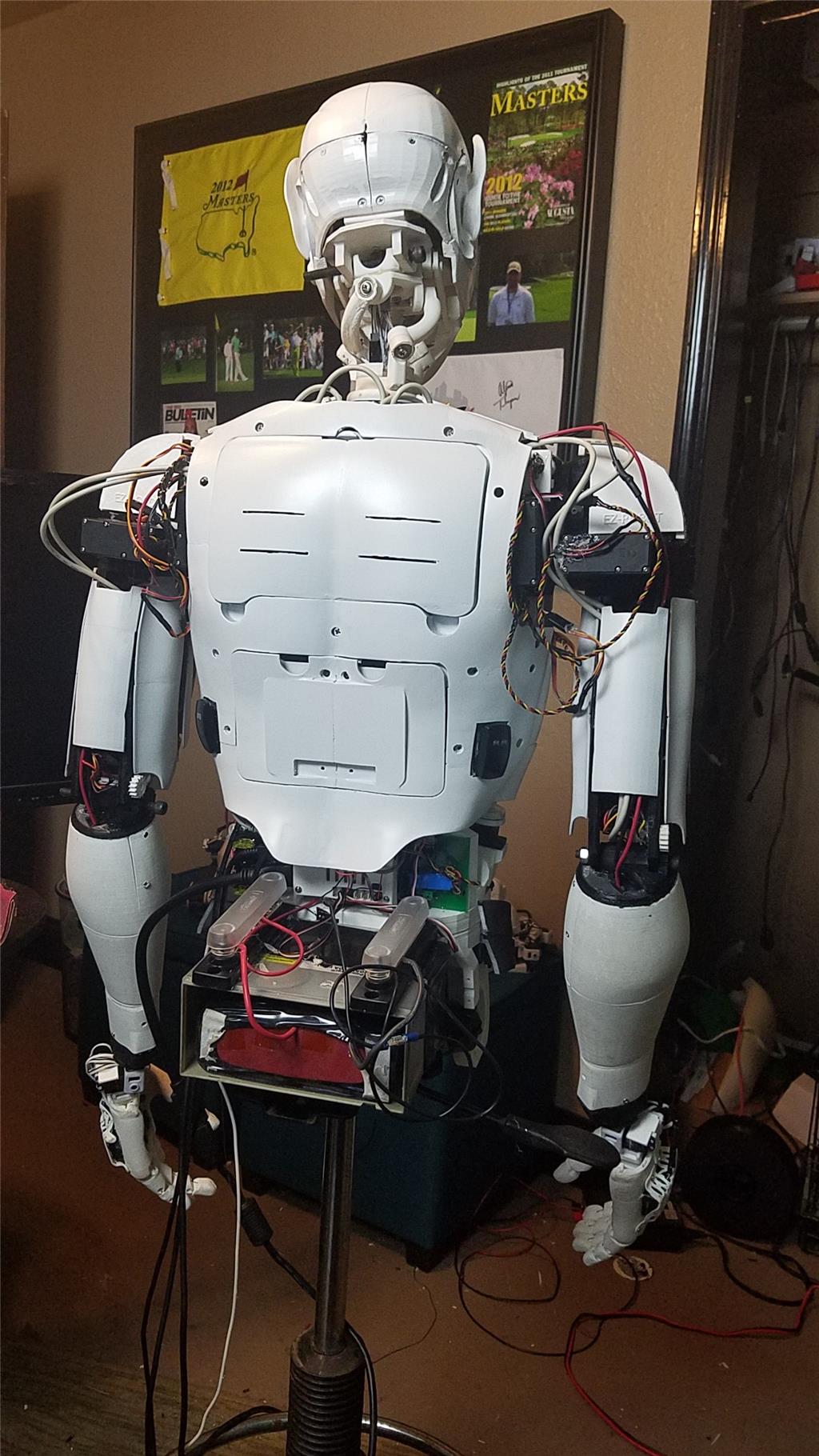
New back of inmoov after other arm has been added. I am working on the reprint of the right forearm and on finishing up the left arm currently.
I have added 3 switches to the back of the inmoov. One controls the power to the left arm and head. One controls the power to the right arm. One controls the power to the lower body. This allows me to be able to kill power to the battery while working on the inmoov and also allows me to work on a zone at a time without having the other zones pulling power needlessly.
There is still some wire management that needs to take place but I will focus on that as a last step of the build.
Hey Ant, the best way I have found to print it is with 2 shells and at .2 mm. The gears I print at .985% scale. I also use grease in the rotational joints.
The shoulder attachments that connect the shoulder to the arm are a pain at best. I haven't found a good way of getting them to connect without breaking at least one tab on them which is then superglue back in place.
I hope this helps. I had to battle the 3d printer today. Both of my z axis idler pulley brackets broke. I was able to get them glued back together long enough to make new ones. Printing again now. Hopefully this fixes the printer for a while.
The information was what I used to get prints that allow the parts to fit together as well as I have found, not only for the gears, but also for the other parts. The gears being printed slightly smaller has helped me. The gears work for me fine when assembled.
That being said (post #111), if you can improve anything, I am sure that the inMoov community would be most grateful as would I.
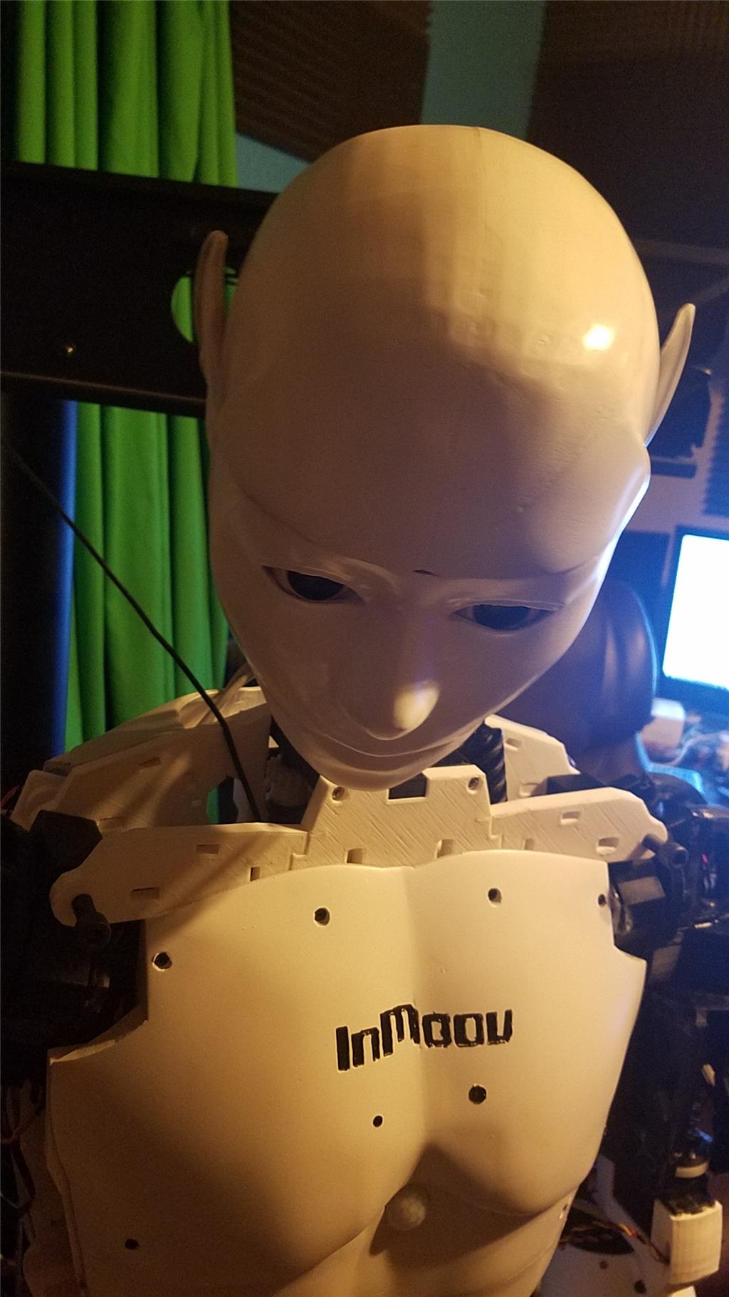
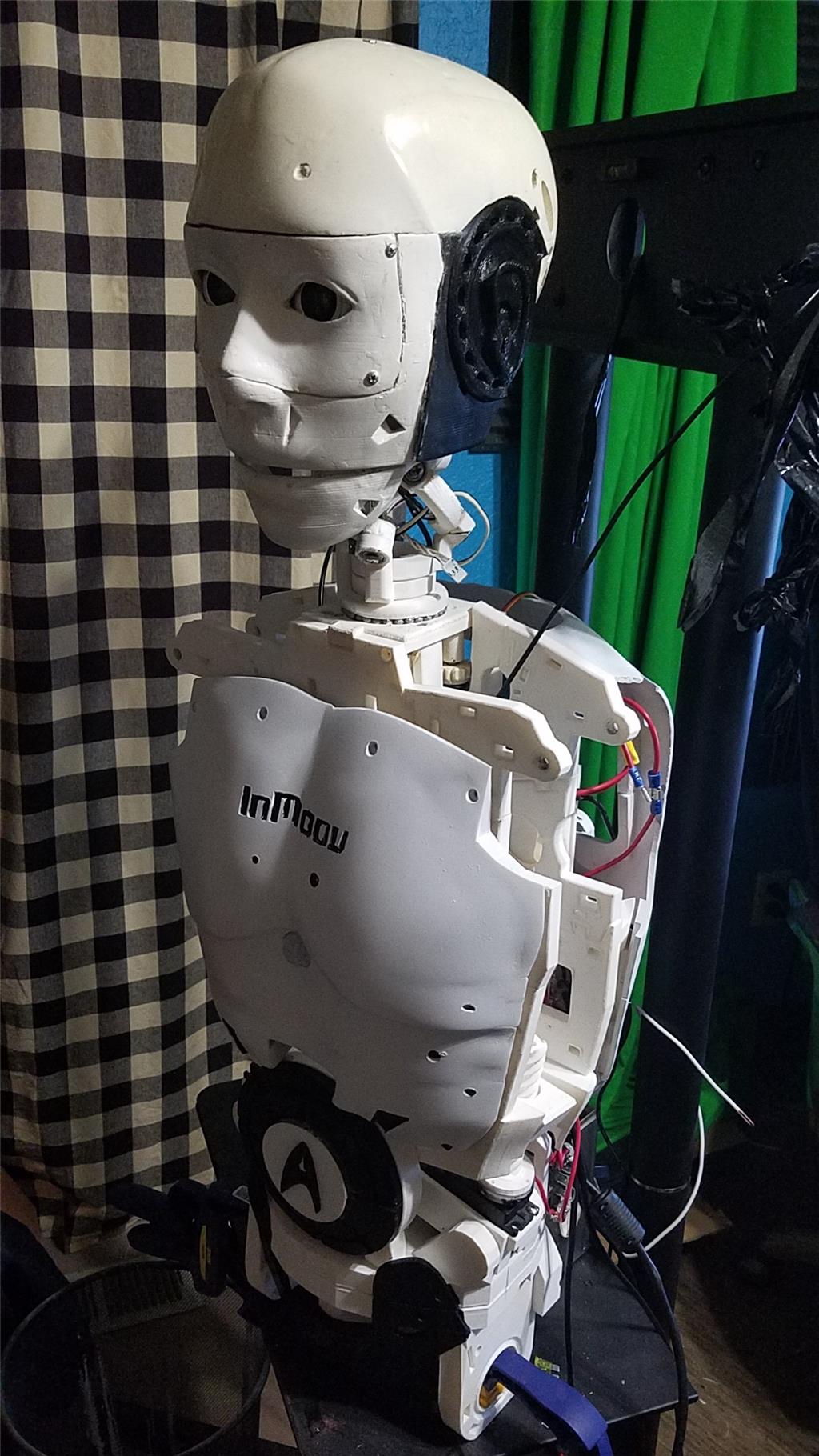
I am in the process of printing BHouston's neck mod. Hopefully it will be completed tomorrow and I can start adding it. I still need to print the covers for the right arm and about 1/4 of the skull. My hope is to have the skull and neck printed by this weekend and then I will finish the arm covers. I am waiting on one more HDMI breakout to complete the right arm. After that it is time to wire him up and see where any issues are.
Also, my work area has moved out of my office and into the garage. There is motivation to get him completed before the hot summer starts...
Ha, ha... sooner or later we (us robot hobbyists) get asked (told) to move our projects to the garage or basement.... Spock is coming along nicely. Can't wait to see an all up test of him...
@D.Cochran - Your inmoov looks excellent and I can't wait to see it operating!