
-636348381130562972.jpg)
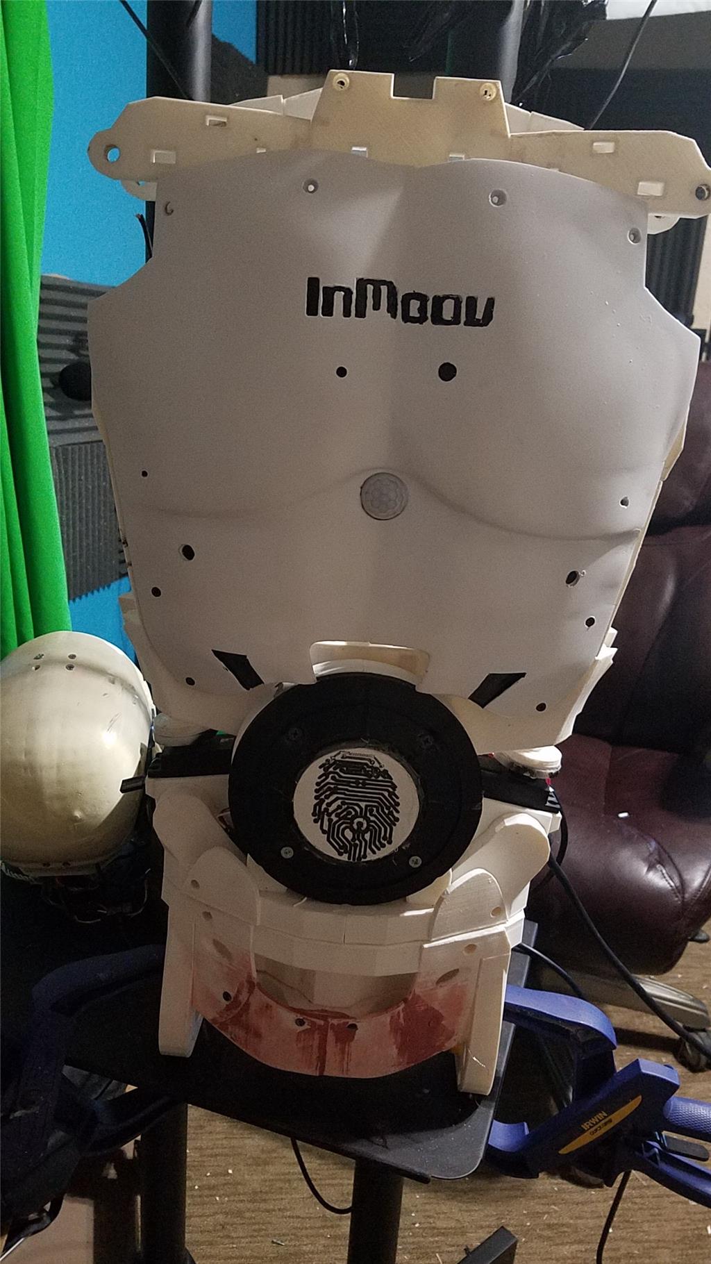


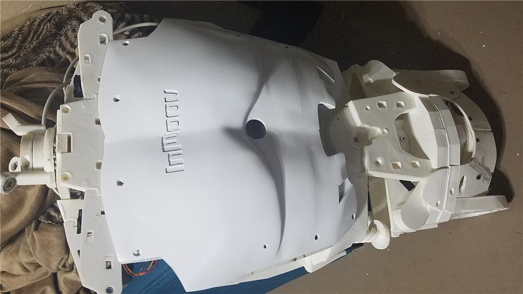
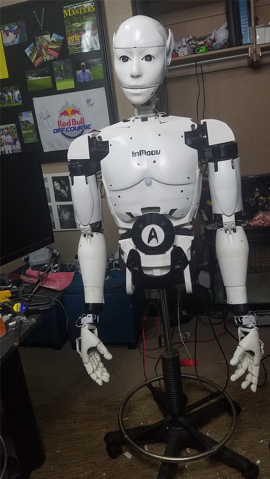
I have decided to start my InMoov project. I think I will call him Spock out of respect to Leonard Nimoy who passed away on the day that I started this project.
I am editing this post so as not to confuse people with the current configuration. I continue to update this post with the latest photos. If you are reading this for the first time, don't be confused. There have been a lot of changes to the InMoov over the past couple of years including starting over.
https://synthiam.com/Community/Questions/7398&page=21 Post 203 starts the rebuild of the InMoov.
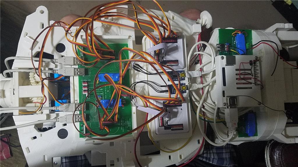
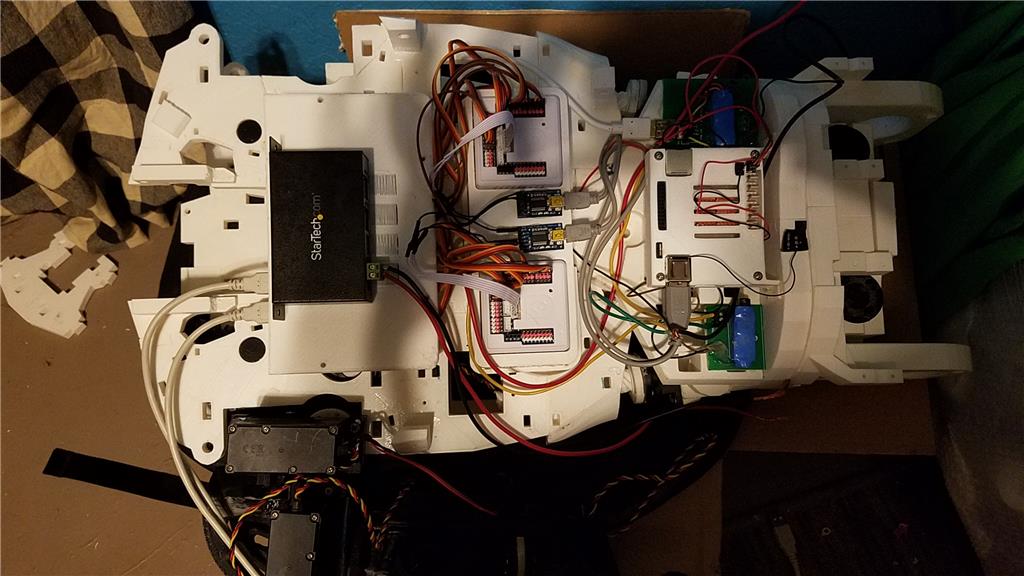
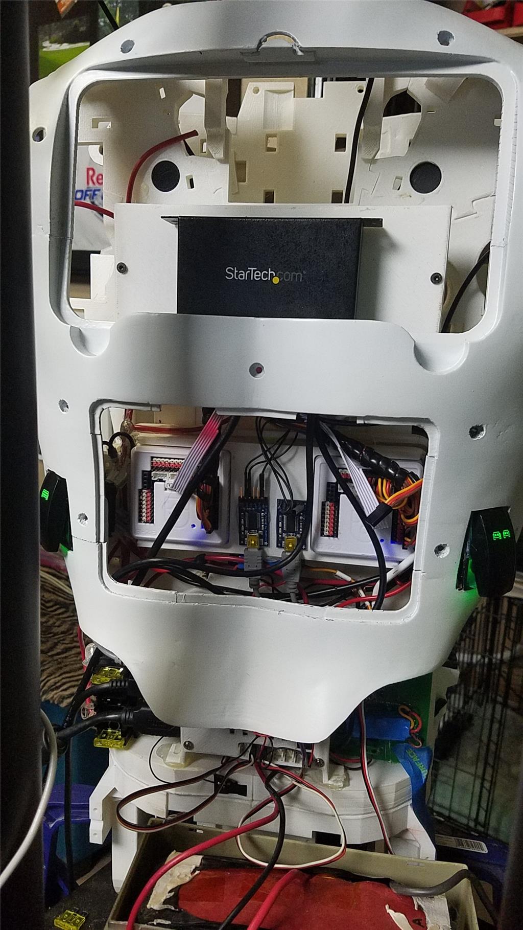
I have decided to use an onboard computer. I chose the Latte Panda due to it having an onboard arduino Leonardo and also because it uses little power.
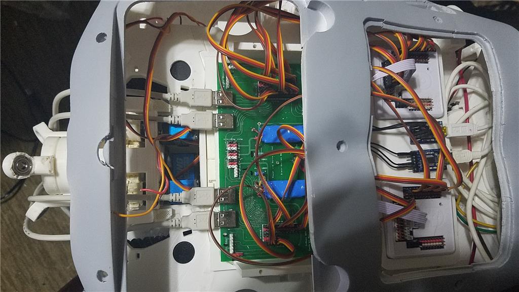
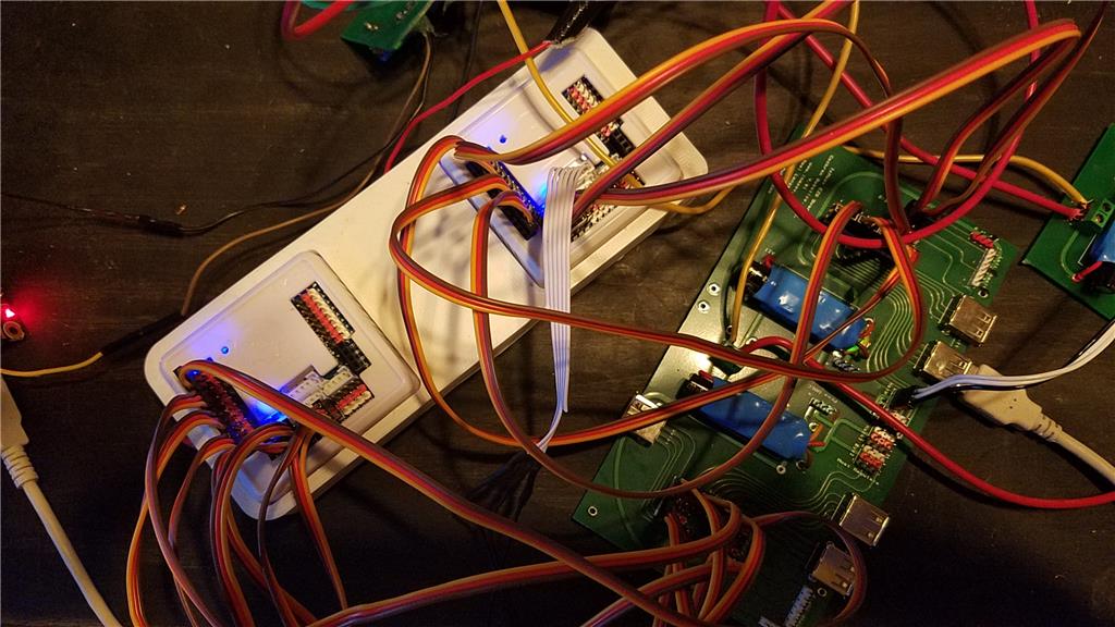
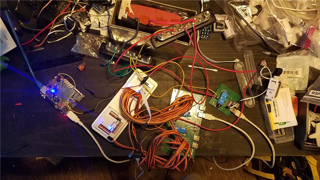
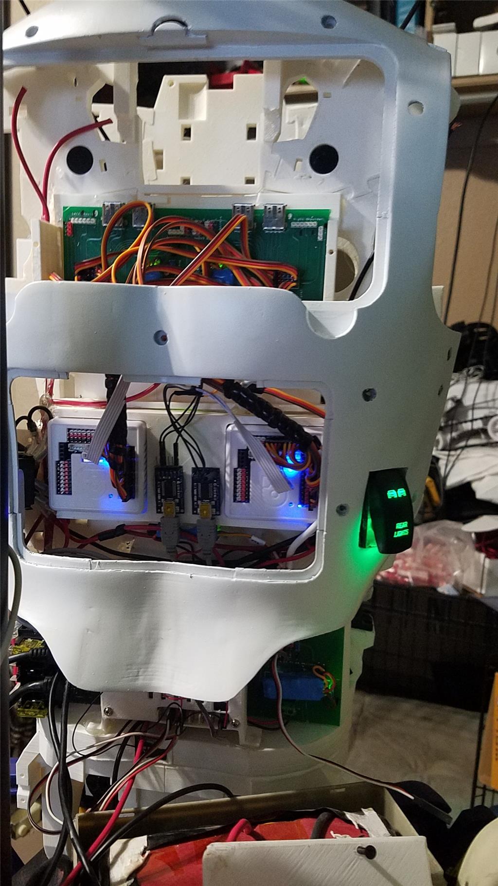
I used 2 EZ-B controllers connected via the camera port to Adafruit FTDI friend boards. This allows the Latte Panda to have a non-wifi dependent connection to the EZ-B's. I use a powered USB hub connected to the USB3 port on the Latte Panda to attach other items.
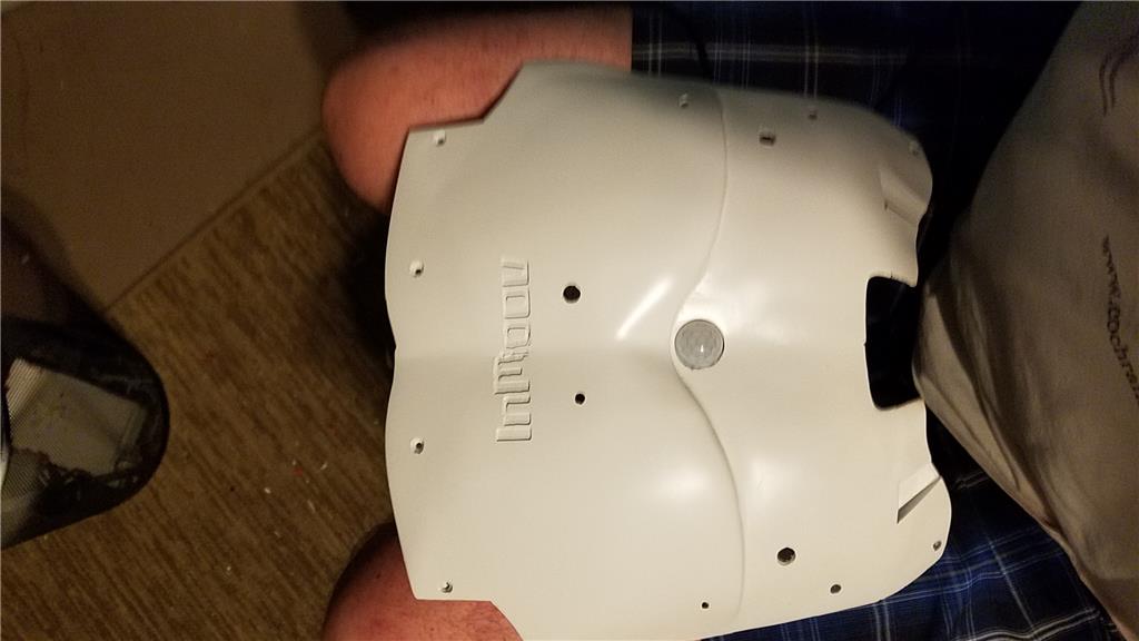
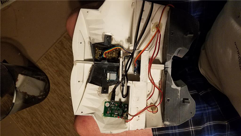
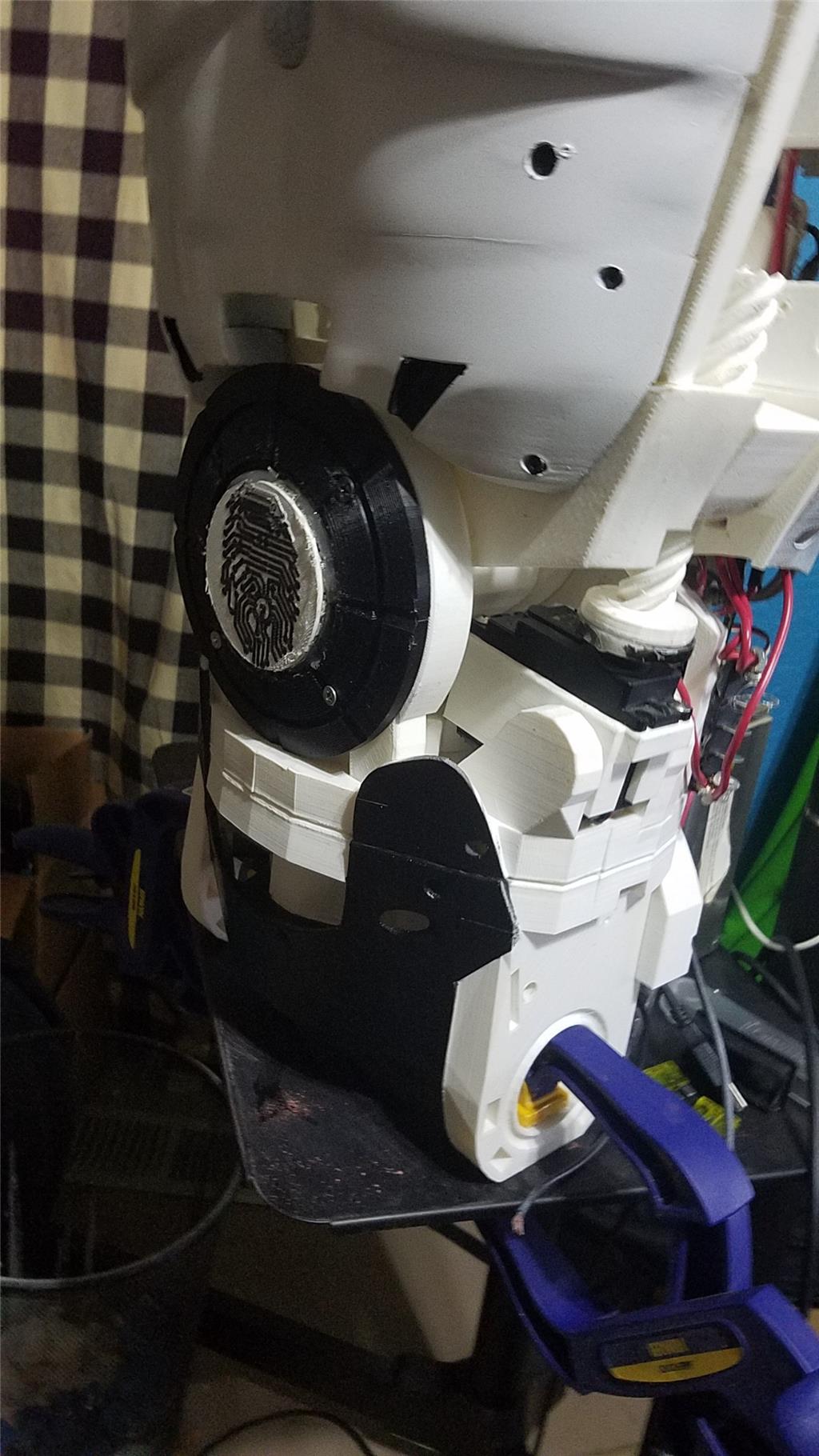
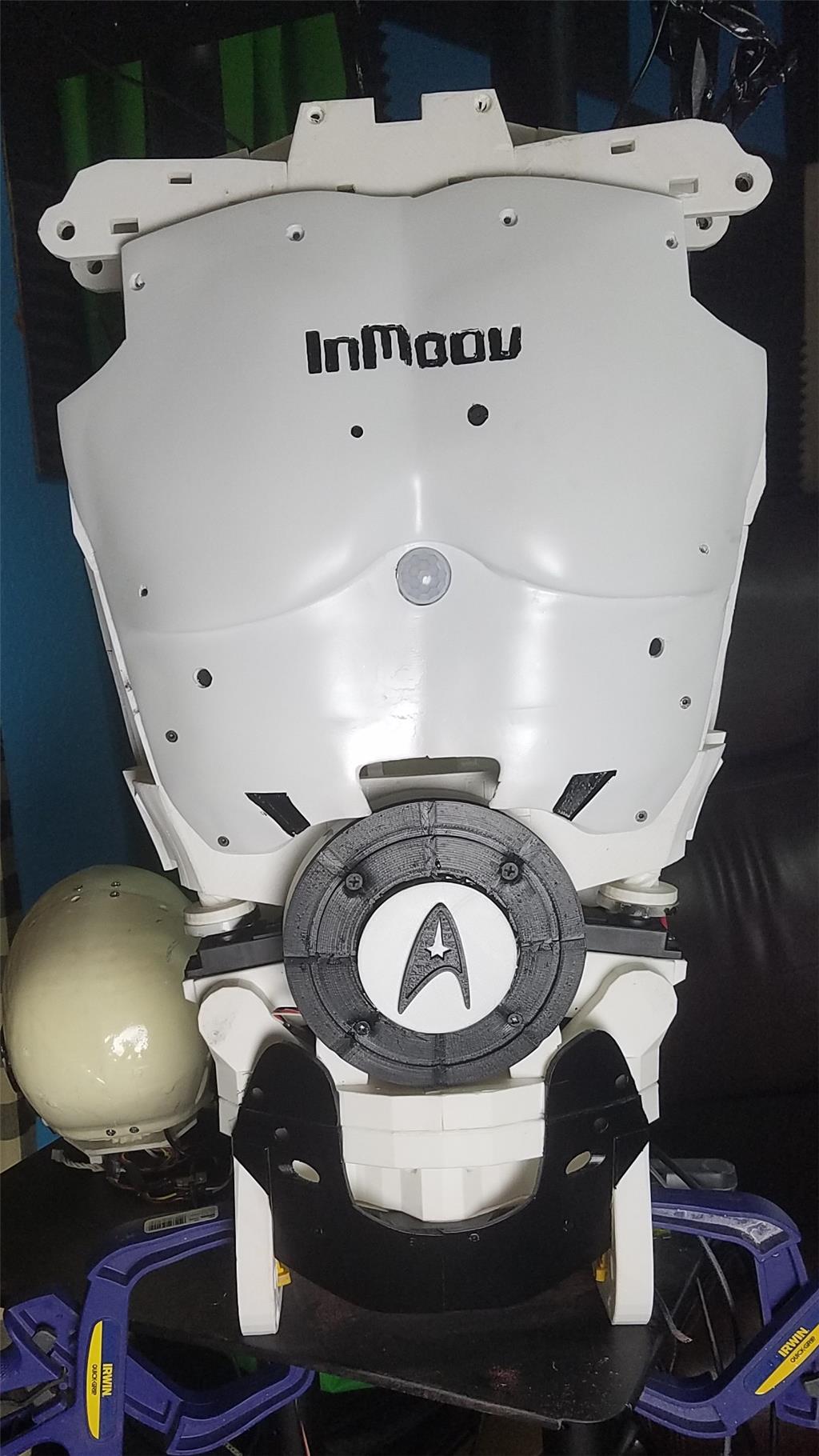
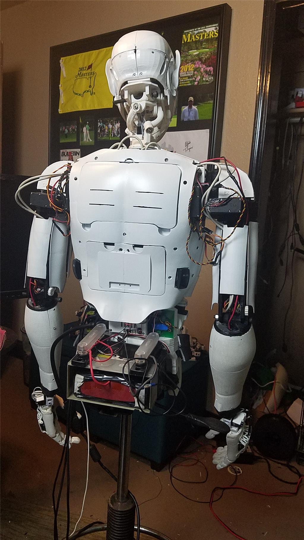
The Omron HVC-P is used to identify people, emotions, human bodies, hands, age and gender. It is attached to the Latte Panda via an FTDI friend which is then connected to the powered USB hub. It is mounted in the chest of the InMoov. I also use a 3 element microphone which is a MXL AC-404 microphone. It is disassembled and the board and microphone elements are mounted in the chest of the InMoov. This mic board is connected to the Latte Panda via a usb cable which is attached to the powered USB hub. There is a USB camera in the eye of the InMoov which is connected to the Latte Panda via the powered USB hub.
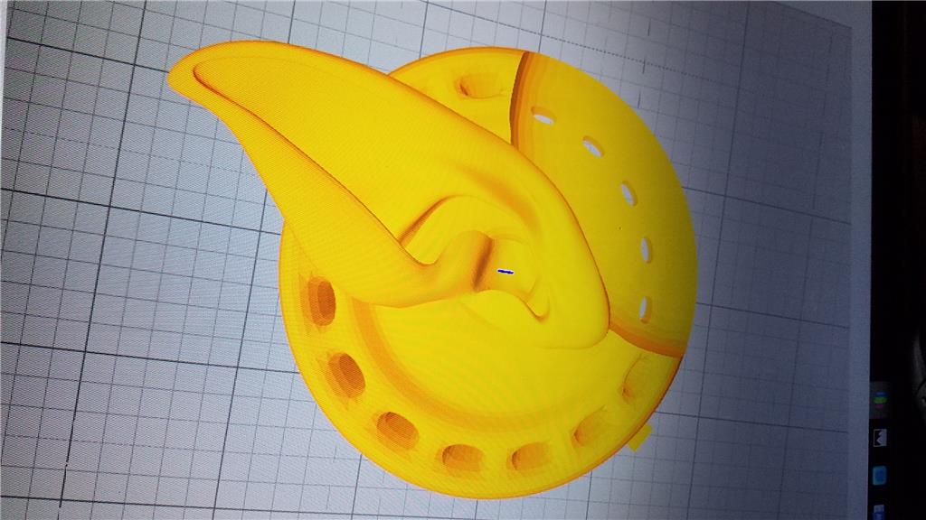
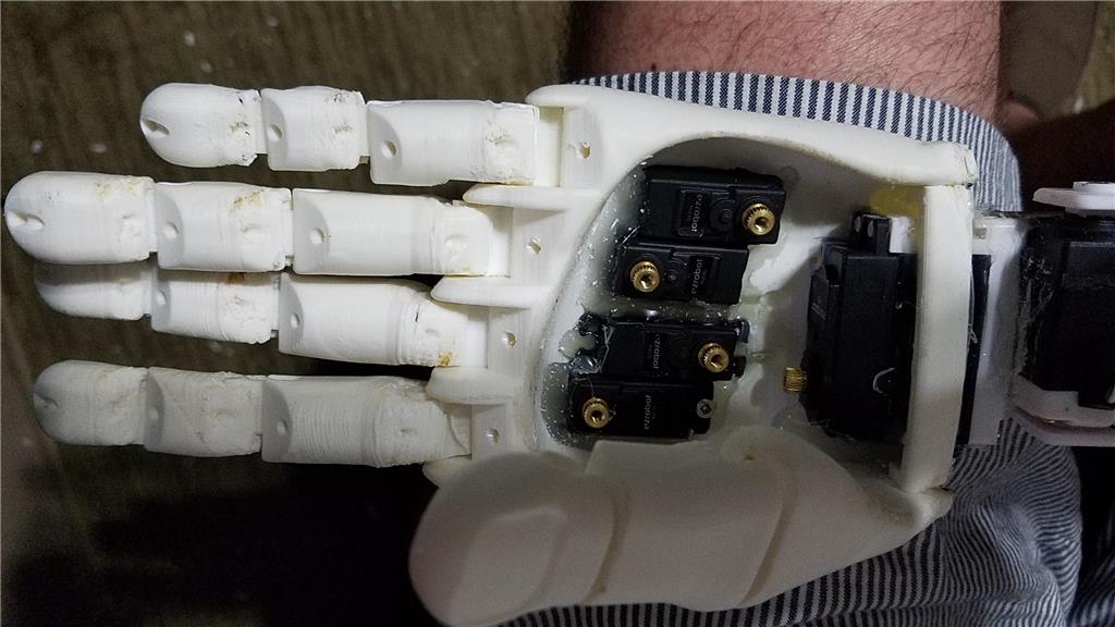
I chose to use the Flexy hand with the InMoov. The design is far more rugged than the original hand and works very well. There are 4 EZ-Robot Micro Servos in the palm of each hand which controls the main fingers. The thumb is controlled by an EZ-Robot HD servo. The wrist waves and uses an EZ-Robot HD servo to do this motion. I use the standard Rotational wrist.
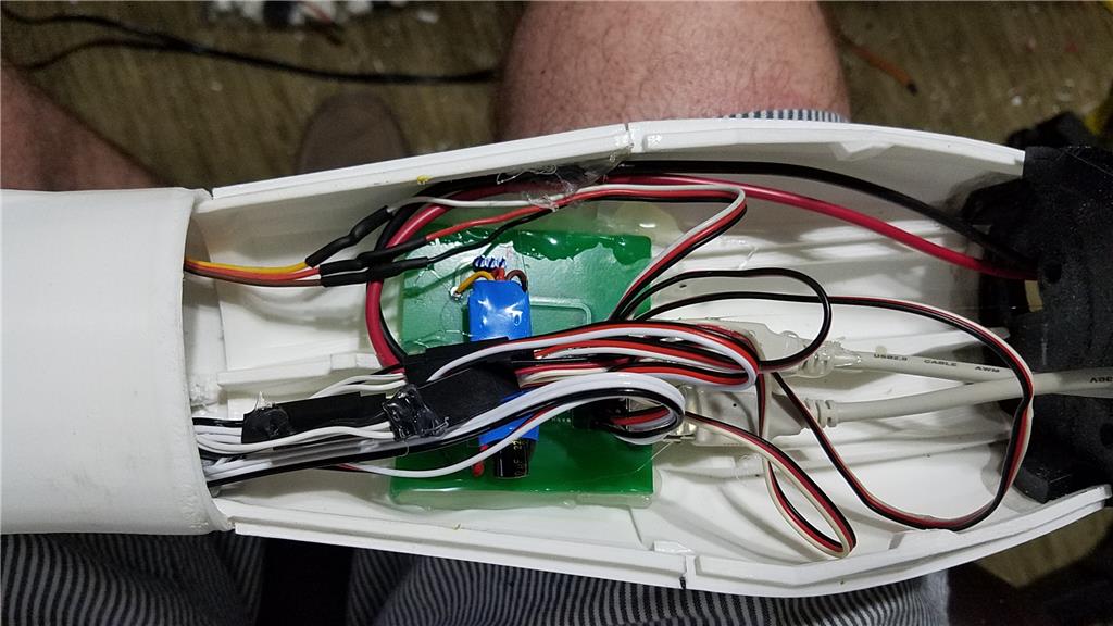
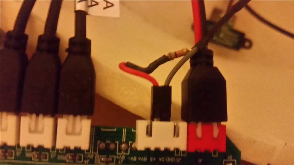
I have castle BEC's for power in the following locations set to the following voltages. Forearm's - 6.2 V - Controls fingers, wrist and elbows Custom power distribution board (2) set to 6.2 V controlling head, neck and Shoulder servos. EZ-B's - set to 6.1 V - it is mounted in the controller mounting plate and connects to the EZ-B fused power boards from a power base. Latte Panda - Set to 5.1 V and is mounted to the EZ-B controller mounting plate. Waist - set to 6.2 V and is mounted in the lower right side of the back. This provides power to the lean and pivot waist motors..
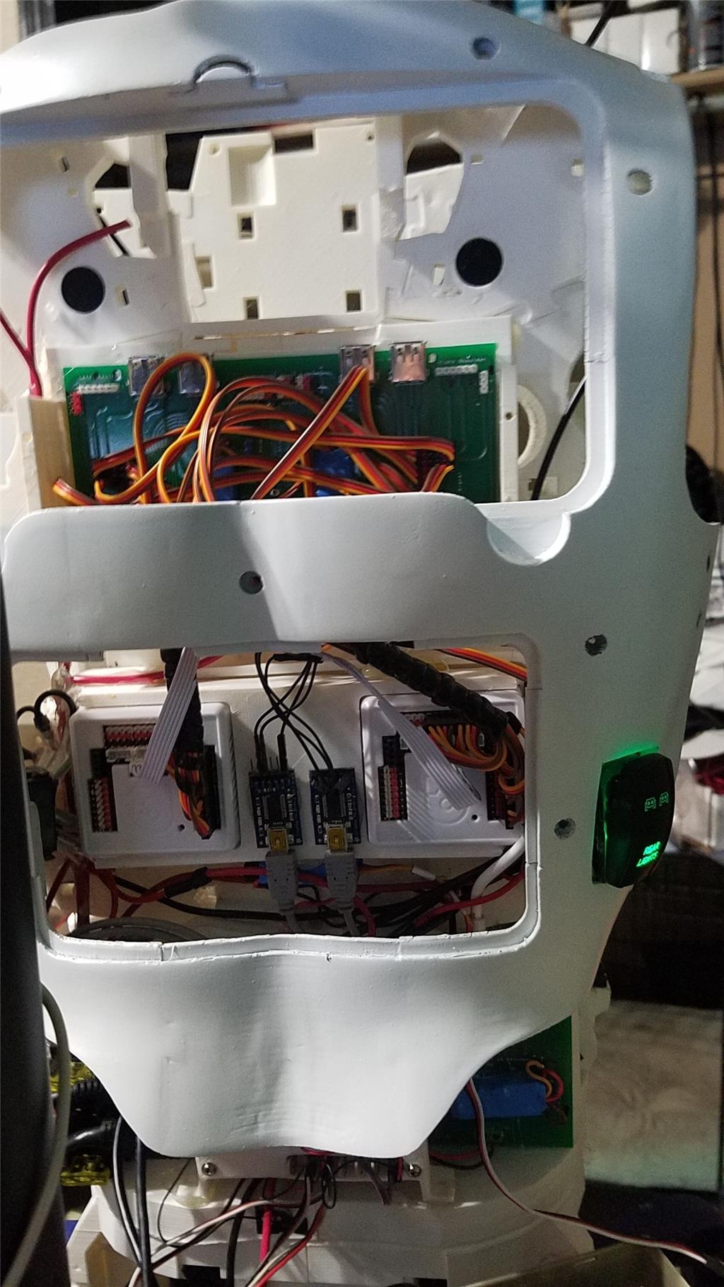
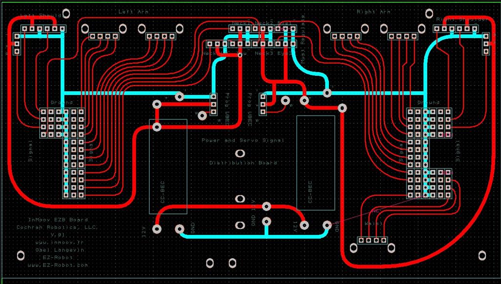
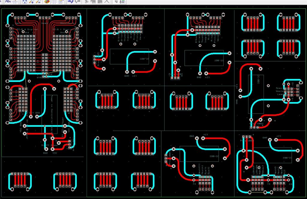
There are some custom power and signal distribution boards. These are in the forearms, lower back and in the upper back. The upper back or main board connects to these distribution points via USB cables to provide signal to the other boards for servos. The main board also has servo connector pins that are for the neck, head and shoulders. This allows the power to be distributed between multiple BEC's and also allows the servo signal cables to be shorter and more protected via the USB cables.
For power I use a LiFePo4 battery that is rated at 30 amps. It has the balanced charging circuit built into the battery and also has a low voltage shutoff built into the battery. This protects the battery and allows the battery to be charged with standard car chargers.
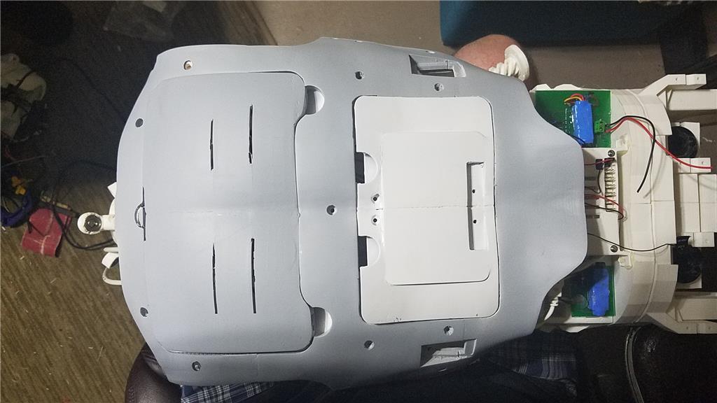
I put switches on the back on the InMoov which are rated at 20 amps at 12 volts. These are rocker switches that allow the user to pretty much slap the switch to turn it off. There are two of these switches. The servos for the elbows and fingers are on one switch. The latte panda, neck, shoulders, EZ-B's, waist motors and some lighting is on the other switch.
I also added a fuse block. This allows 20 amp fuses to be put in line to help protect things. The switches above drive the fuses for each of of the motors listed in that section.
-636348716348649435.jpg)

Discover more robots
Ezang's My New Adventure Bot
Ericez's Droid For Theater Robot Contest
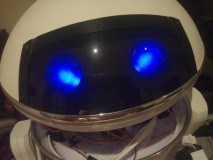

OMG that's awesome and creepy at the same time!
Yea, my daughter heard it and ask when the inmoov became possessed. I laughed because she doesn't realize what was happening.
She is kind of creeped out by the inmoov build anyway. I cant wait until its standing outside her door when she walks out of her room.
Ha, ha, that's funny David..... That's the reaction I usually get when people see my inMoov for the first time..... "That's so creepy".... after a bit they come around and are usually in awe of it being so life like....
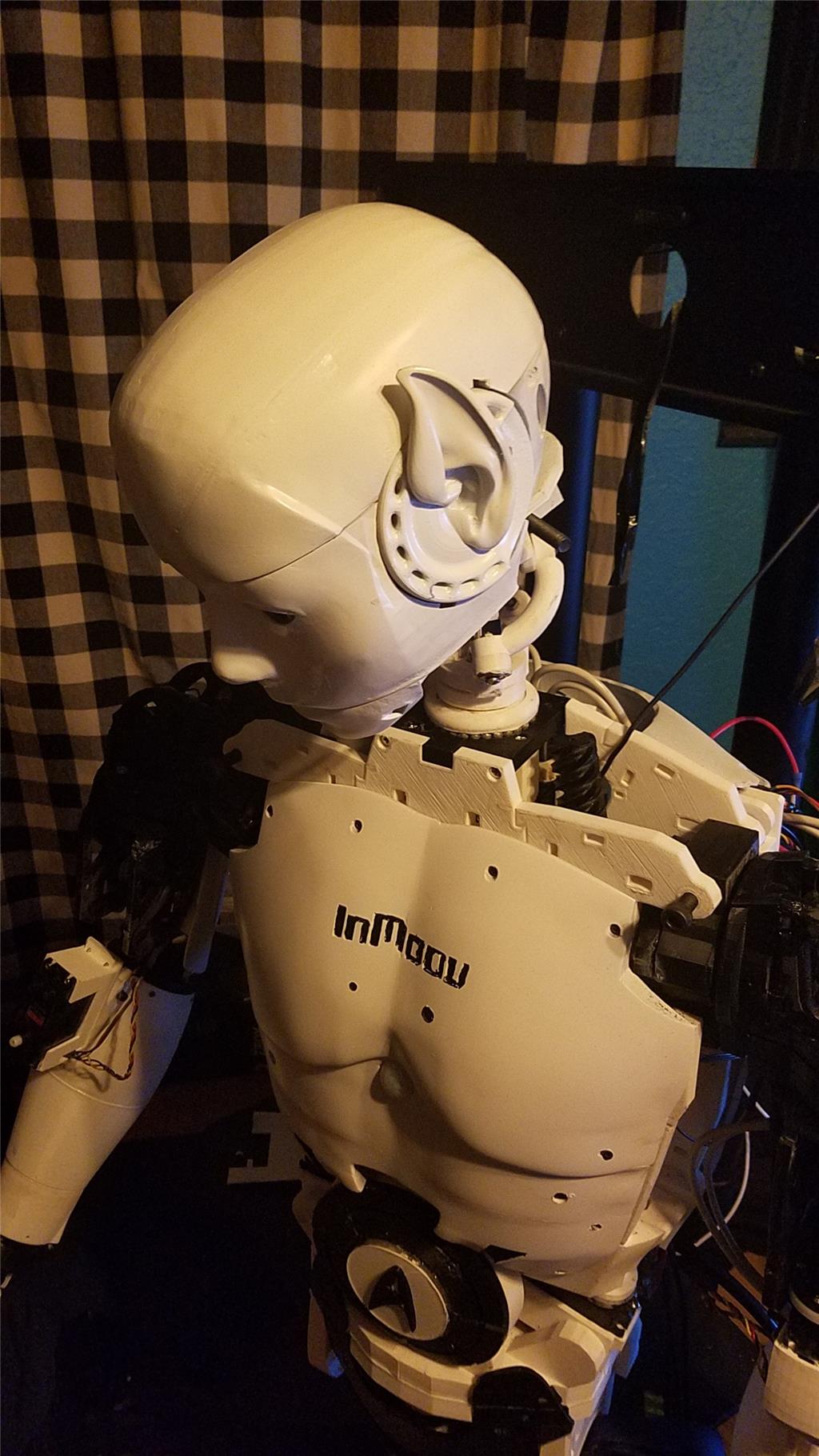
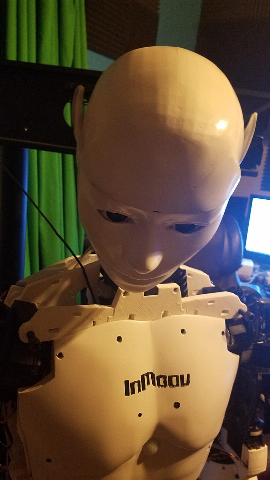
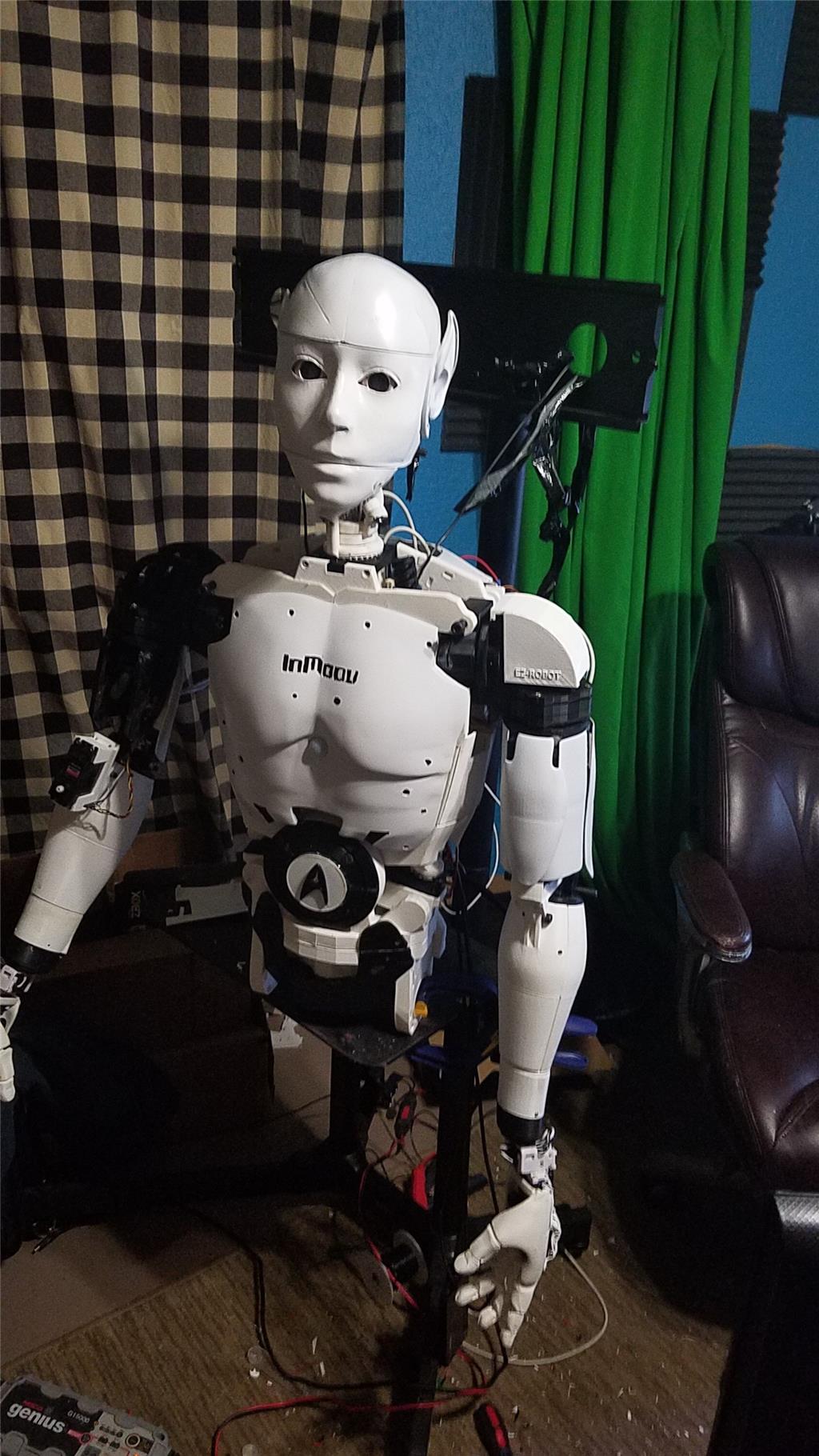
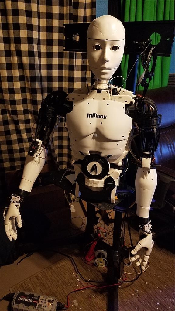
I have decided to reprint the inmoov. I have use of a 3D printer this summer and figure that I might as well reprint it in the colors that I want. I am looking for a white and black scheme with my inmoov. Right now, my parts are natural white. I also want to print everything in ABS anyway. Because I will be doing a lot of printing this summer, I have decided to purchase Simplify3D. I have printed a couple of parts with it and am pretty impressed with the results. I haven't quite got every setting in it fine tuned but the default settings for my printer are better than what I could get with Slic3r and Repetier. I am still tweaking the settings while printing the parts and have been improving the quality with each part.
The main reason that I want to go with ABS is strength. It also allows me to use Acetone for part bonding which I like better than glue. The parts just come out more clean for me and also are bonded instead of glued, adding more strength.
This is going to take some time to complete, but I think it will be worth it in the long run. The current build is being used to test everything and allows me to experiment with wiring and other things. It also has allowed me to go through a build once already, which helps me to understand how the build works. I think that this understanding will help my final build to be more accurate. I will donate the current build to the school that I work with (minus all of the electronics) which will allow the students to gain an understanding of many different aspects of robotics. It also helps me to be more patient knowing that there is an inmoov in my closet that I can experiment with.
All of this is just to say that this build is going to take a lot longer than I had originally anticipated. All good for me as it is a learning process and I want to get everything correct.
I agree David... My inMoov is/was basically printed twice... I gradually got better at printing, sanding and fit and finish... So my first gen parts that I wasn't particularly happy with were reprinted to look, work and fit much better....
There is no hurry... There's a lot of work, no doubt... it's a great journey so to speak... What I liked about it the most was learning new disciplines a long the way... I can hack a servo with the external pot mod in about 20mins now... First one I did took nearly an hour to do LOL....
Hi David,
I'm enjoying following your build and how it's developing. Your making some great design and build decisions. Looks like your having a lot of fun and learning as you go. Isn't that what life's about anyway?
As long as your rebuilding I have a suggestion for your build that may help. I noticed you are using some very large power regulators with big and probably heavy heat sinks attached to the back of you build. After reading the specs on them I cant really tell If they are Linear Regulators or Switching Regulators. Switching Regulators are usually smaller, lighter, run cooler, use and waist less battery power. Castle Creations has two Regulators that may serve you better. They offer a 10 amp peak and a 20 amp peak Switching Regulator. They are amazingly small, light and well built. While these two offerings handle a little less peek amps then what you have now you could easily run two and split your load.
Input voltage is variable and output is adjustable (additional hardware is needed to set output voltage through your PC but is easy to do).
I'm running two of the 10 amp regulators in one of my B9 arm and am very happy with it's performance and compact size. It weighs nothing and can be hidden almost anywhere. The 10 amp model has three wires on the regulated side but you only need two of them. Find the two the deliver the regulated voltage, clip and tape off the third.
I thought I'd mention this because in Robotics we always seem to be looking for ways to lighten weight, cut power consumption, have things run cooler and more efficient. I thought this may help you do some of this with your build.
Look over these specs in the link below. You may find if they are within your needs these two regulators may work better for you then your present regulators. You can find them on Amazon.
CC BEC Pro Switching Regulators
Castle Link Programming Kit (about 23 UDS on Amazon):
Hey Dave. I agree that BECs will be a better option. I haven't made it to that part so much. I do plan on upgrading to BECs at some point. I wasn't sure (and am still not sure) if I will go with 24 or 12 volt motors in the base for mobility. As you know, this plays a huge role in what I use for voltage regulation. The ones I bought will handle 12 or 24 volt, so I opted for them initially to allow me to see test a 24 volt or 12 volt system. I want to go 12 volt for a number of reason and will try that first. If it works out, I will be able to make a choice on which BECs to pick up.
Thanks for following the build and offering suggestions. They are much appreciated.
Just a status update...
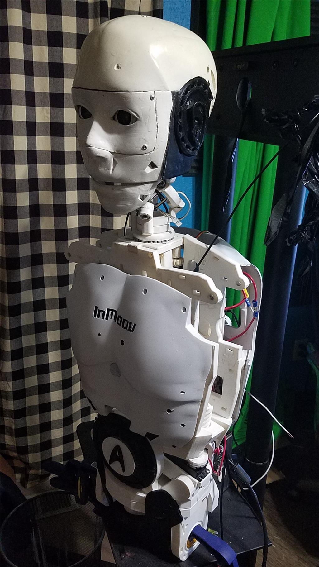
One arm built with new colors and a few changes to the colors on the inmoov body. I will be finishing the other arm and then going on to reprinting the head. A few of the PLA pieces (mainly gears) have broken. The jaw gear broke when I was fine tuning my scary terry board, so while I am fixing that, I figure that I might as well try to tighten up some things in the head.
As far as the solidoodle goes, I have printed about 3 KG of ABS through it. I think the results are pretty good. You get what you pay for and it is a $600 printer, but for $600, it does a really good job. I am still split on what to buy for a 3d printer so I am going to hold off until the end of the summer, and use this one until then.