


-635353562186322812.png)


Hi all,
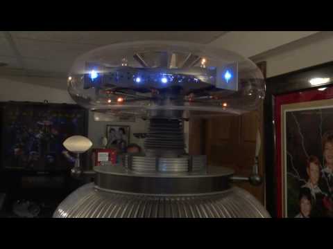
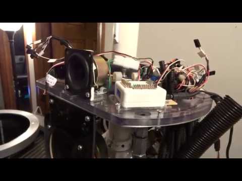
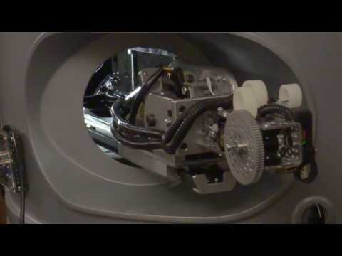
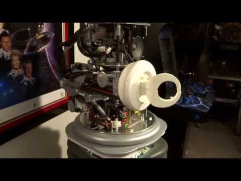
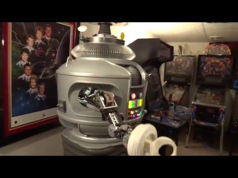
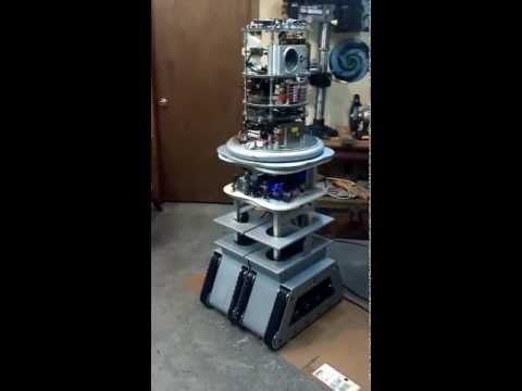
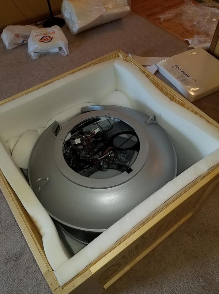
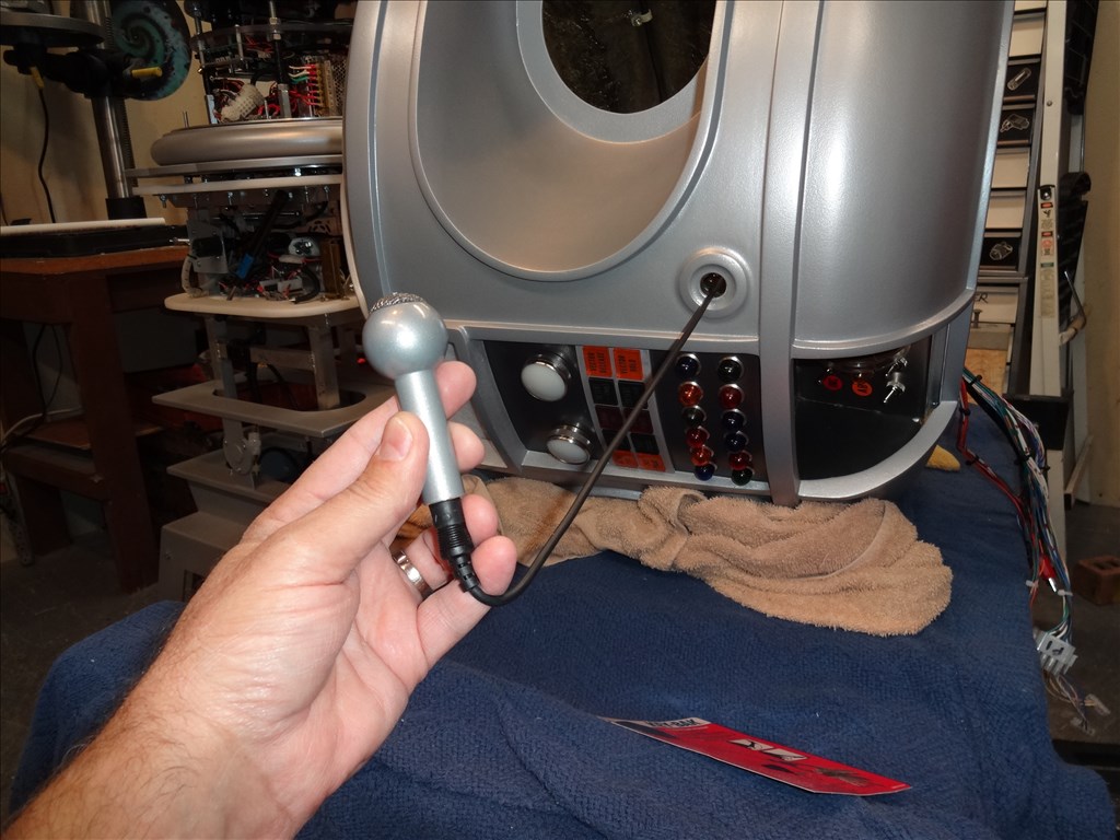
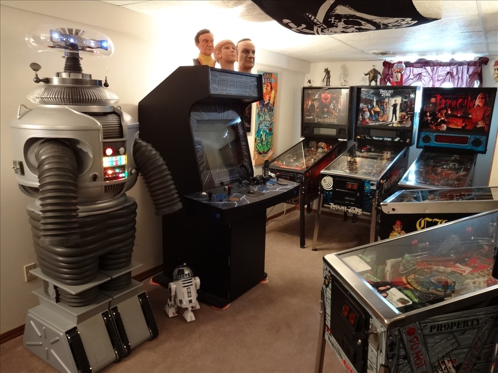
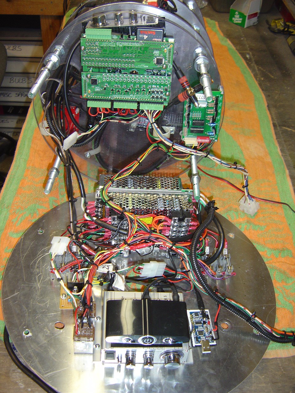
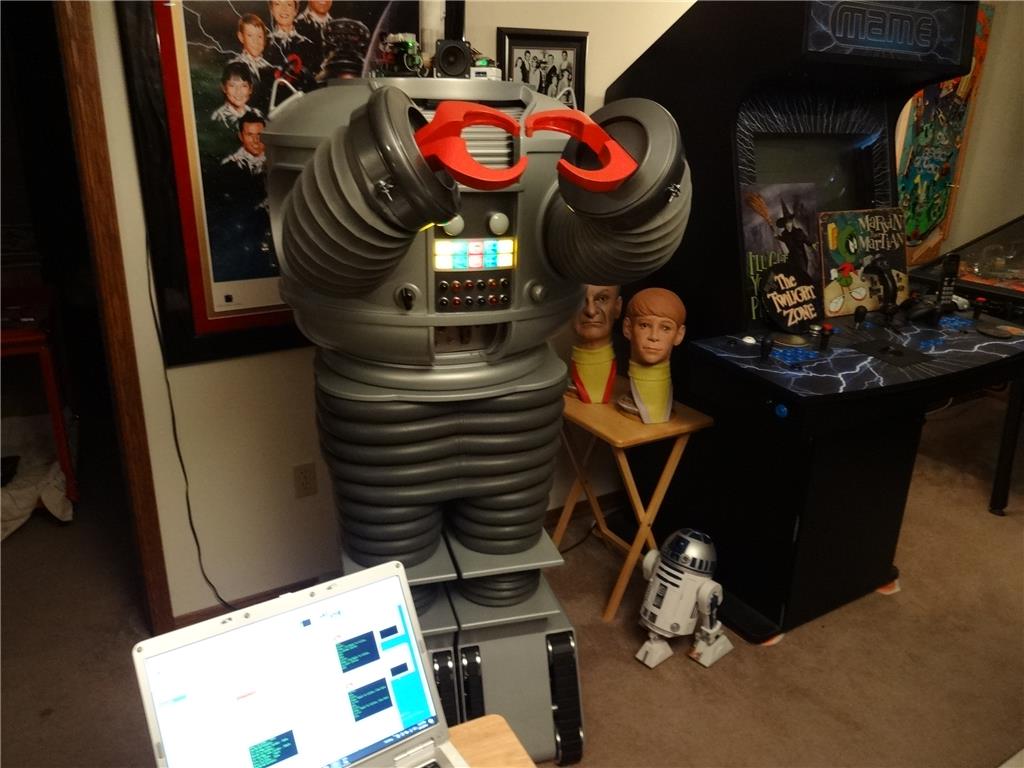
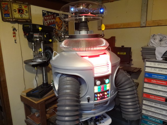
I'd like to share a video I just took of my full size Lost in Space B9 robot that's controlled by two EZ-B controller boards. Right now they are controlling limited movement and voice response of a few motors, lights and sound files played from a Sparkfun MP3 Trigger board. Although I'm just starting with the animation and have more building on the actual robot the result (mostly thanks to the EZ Robot controller board) is shocking. Please have a look at this (4 minute) You Tube vid and enjoy.
Please excuse some Technical camera lighting and sound issues. This is the first time I'd made and posted a vid online.
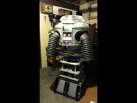
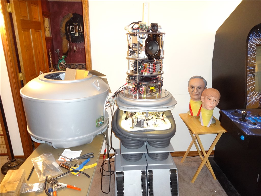
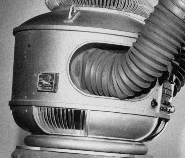
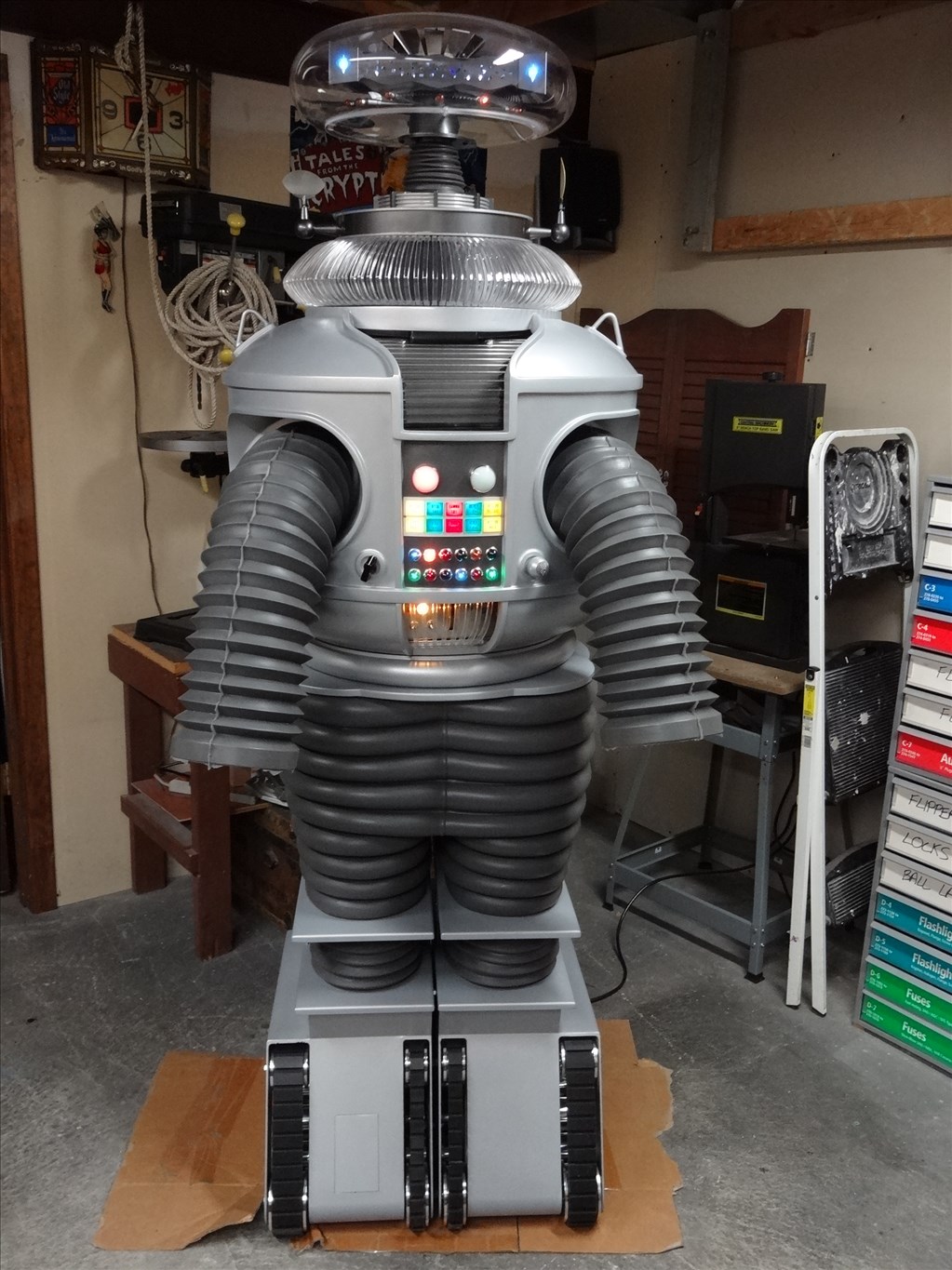
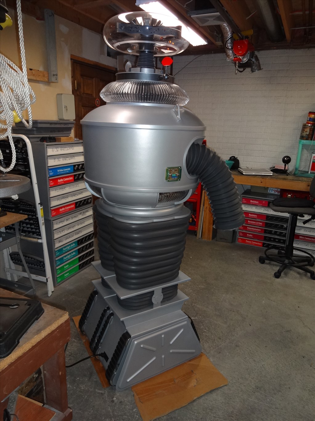
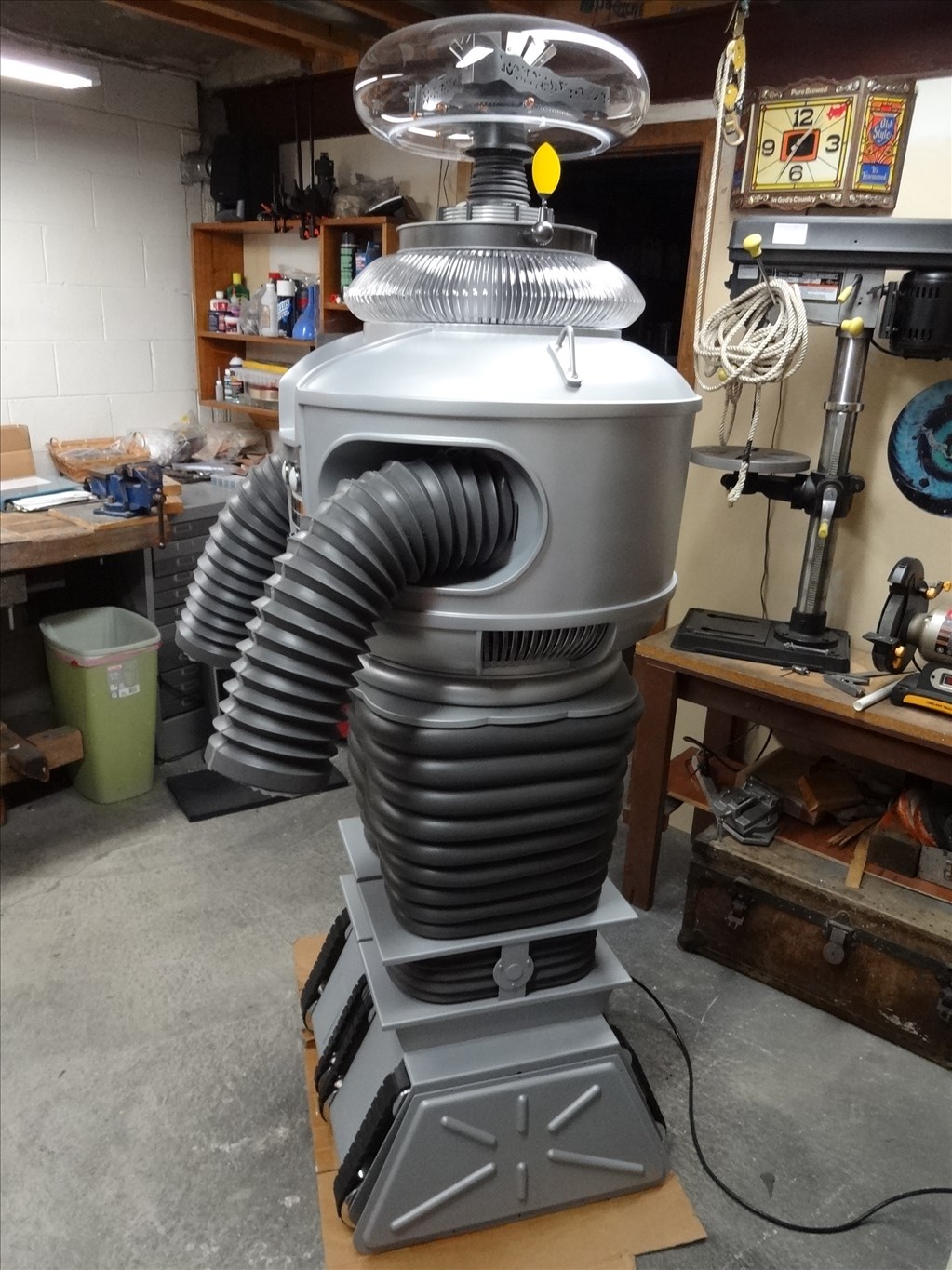
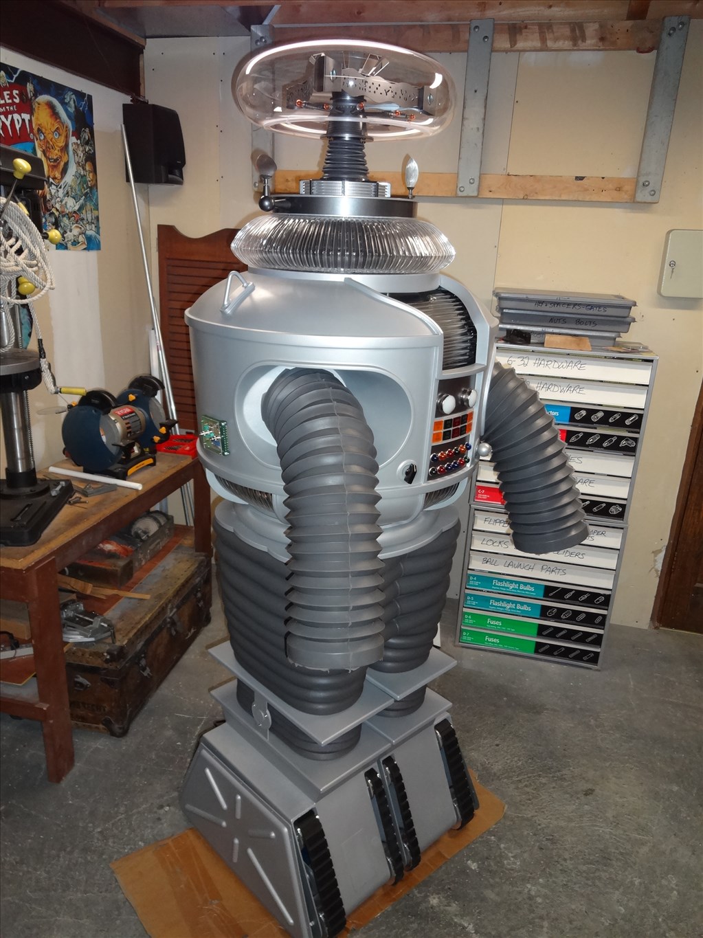
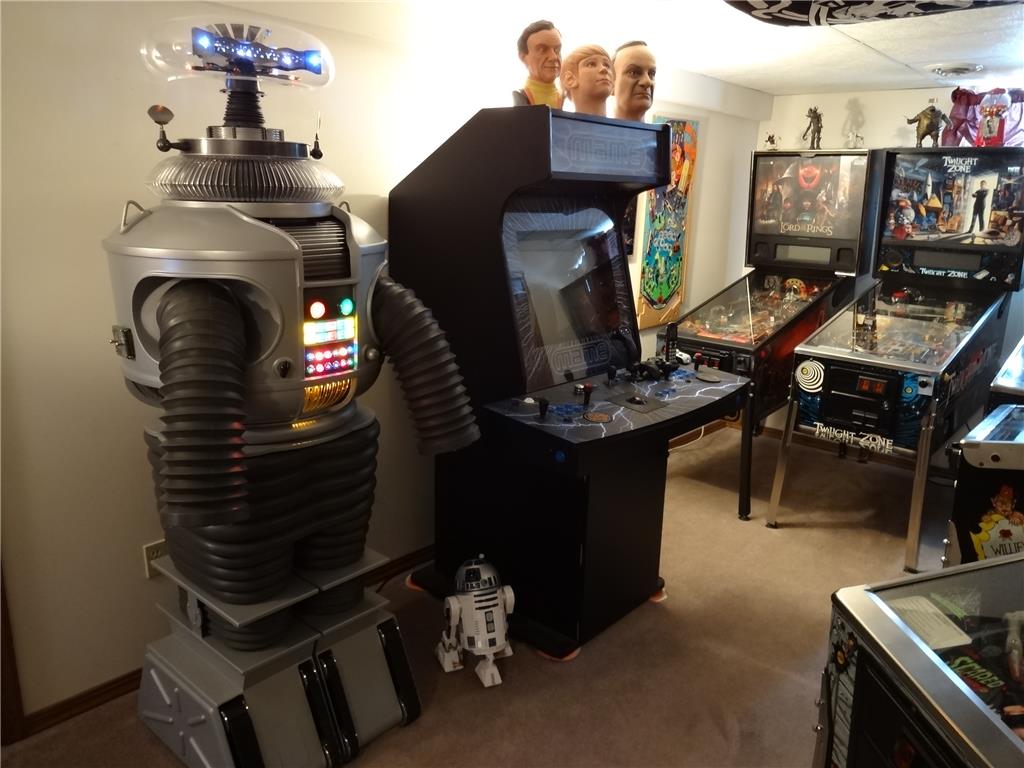
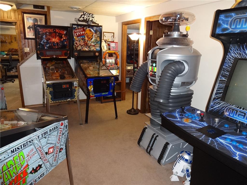
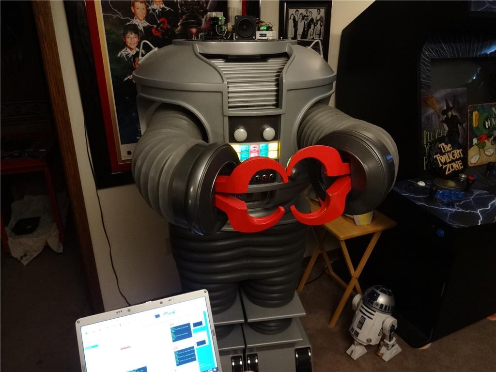
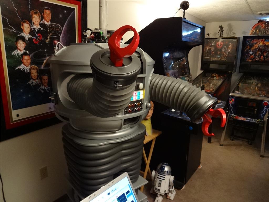
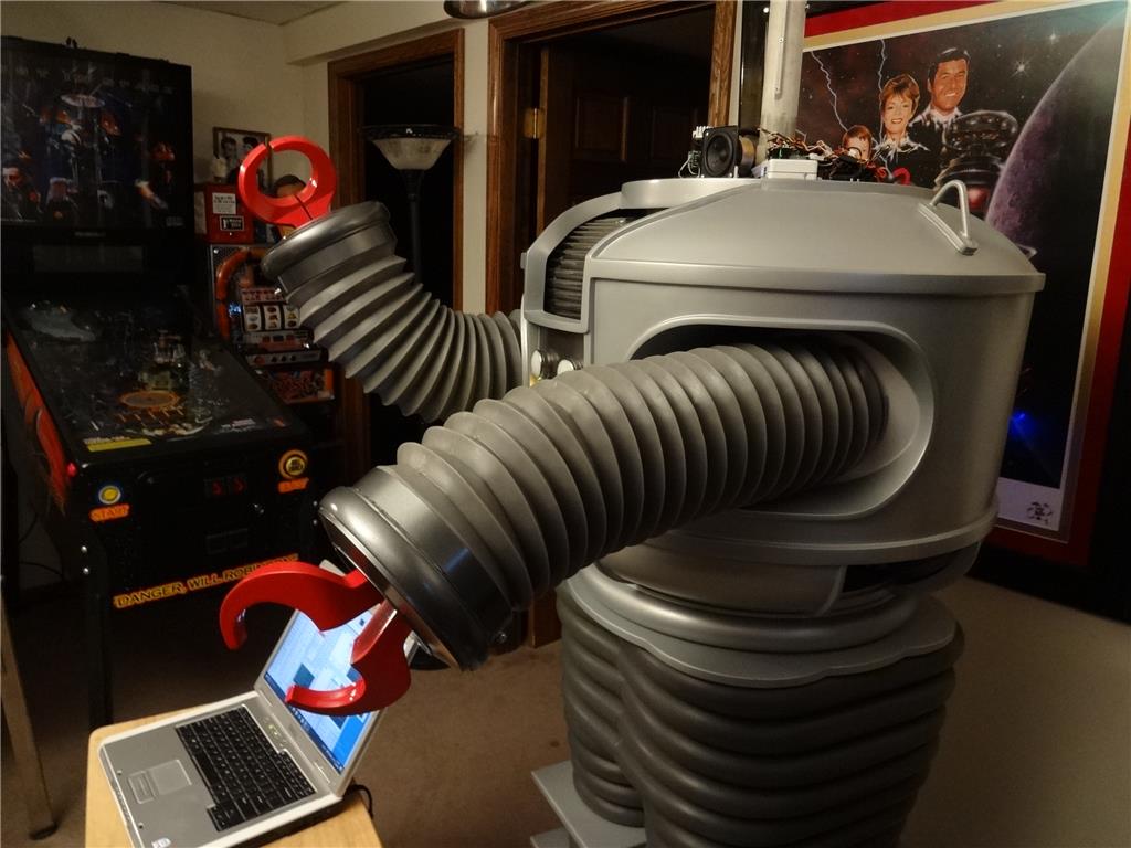
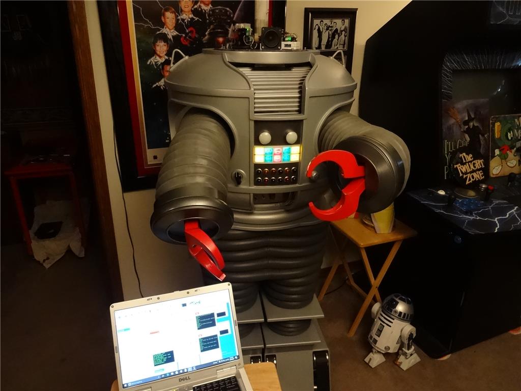
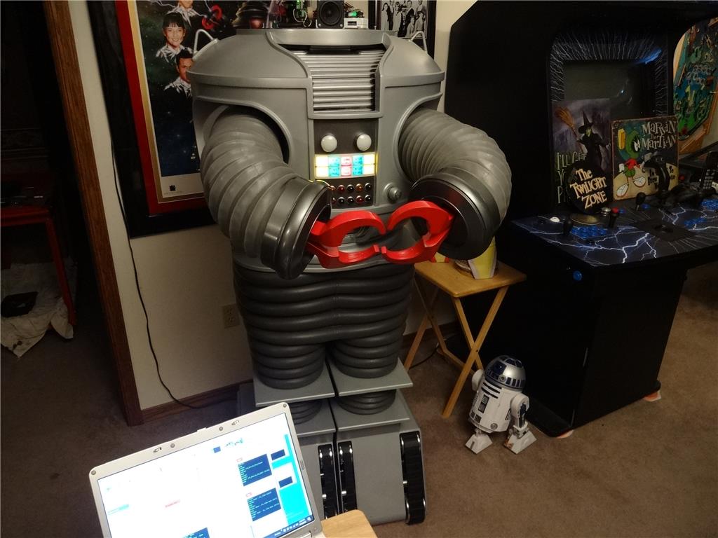
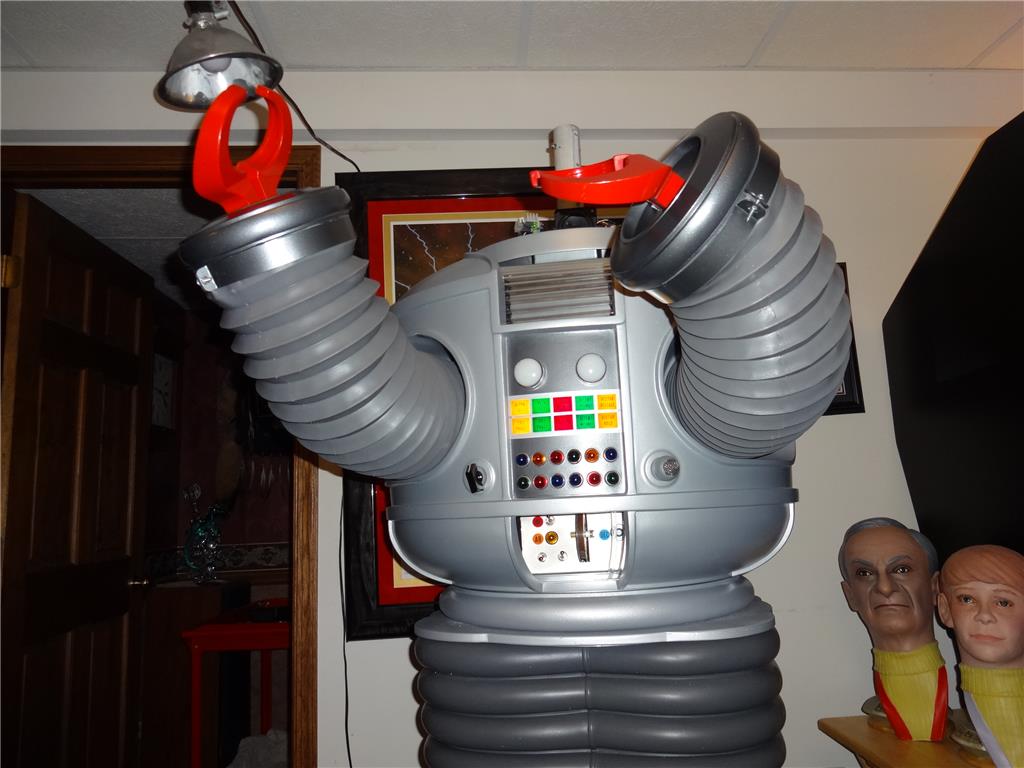
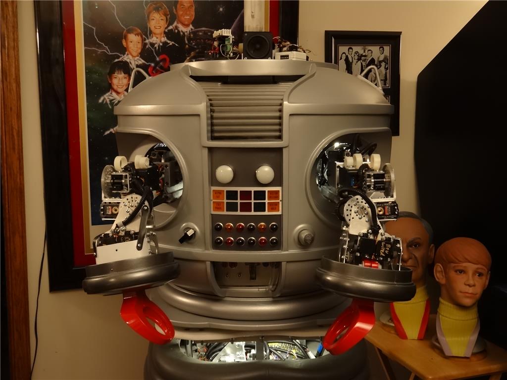
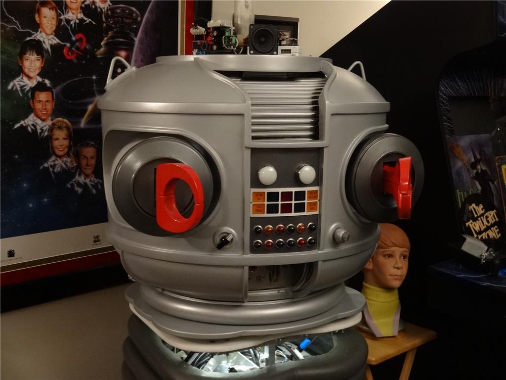
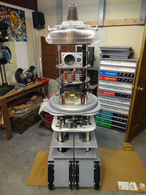
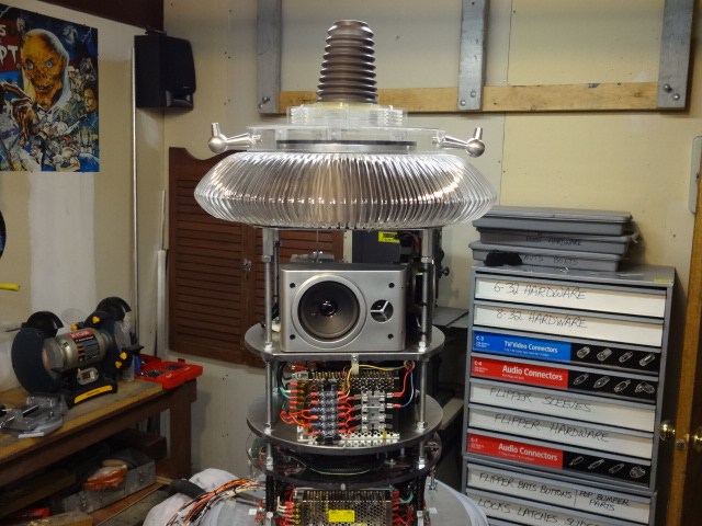
EDIT 8/2/13: Just realized I have no good pictures of how my B9 will look when complete. Here's one of the actual TV robots from the 60's TZ show Lost in Space and one recent shot of where I'm at with my build over 1 1/2 year after I started. Enjoy:


Thanks, Dave Schulpius
Discover more robots

Steve's Marcus The Expressive Android
Wolfie's Well Its A . Start


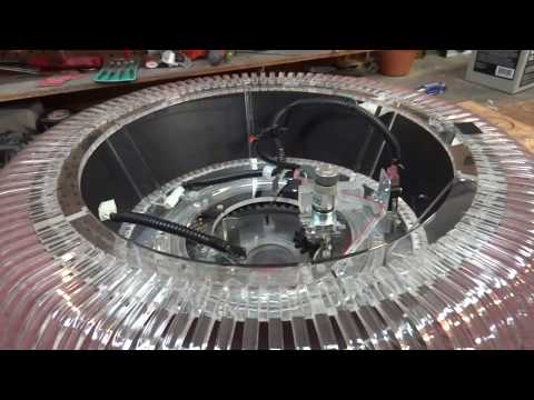
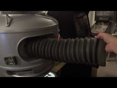
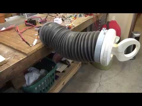
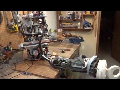
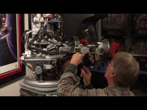
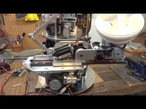
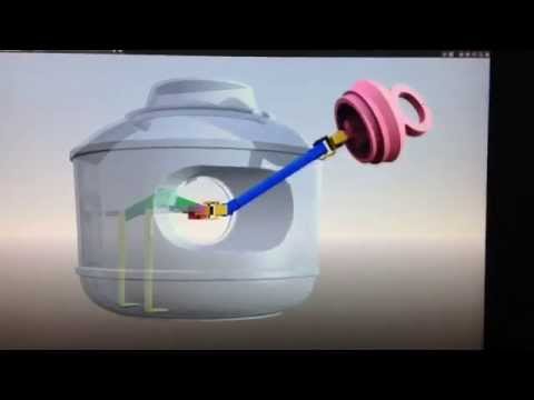
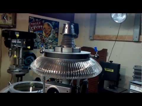
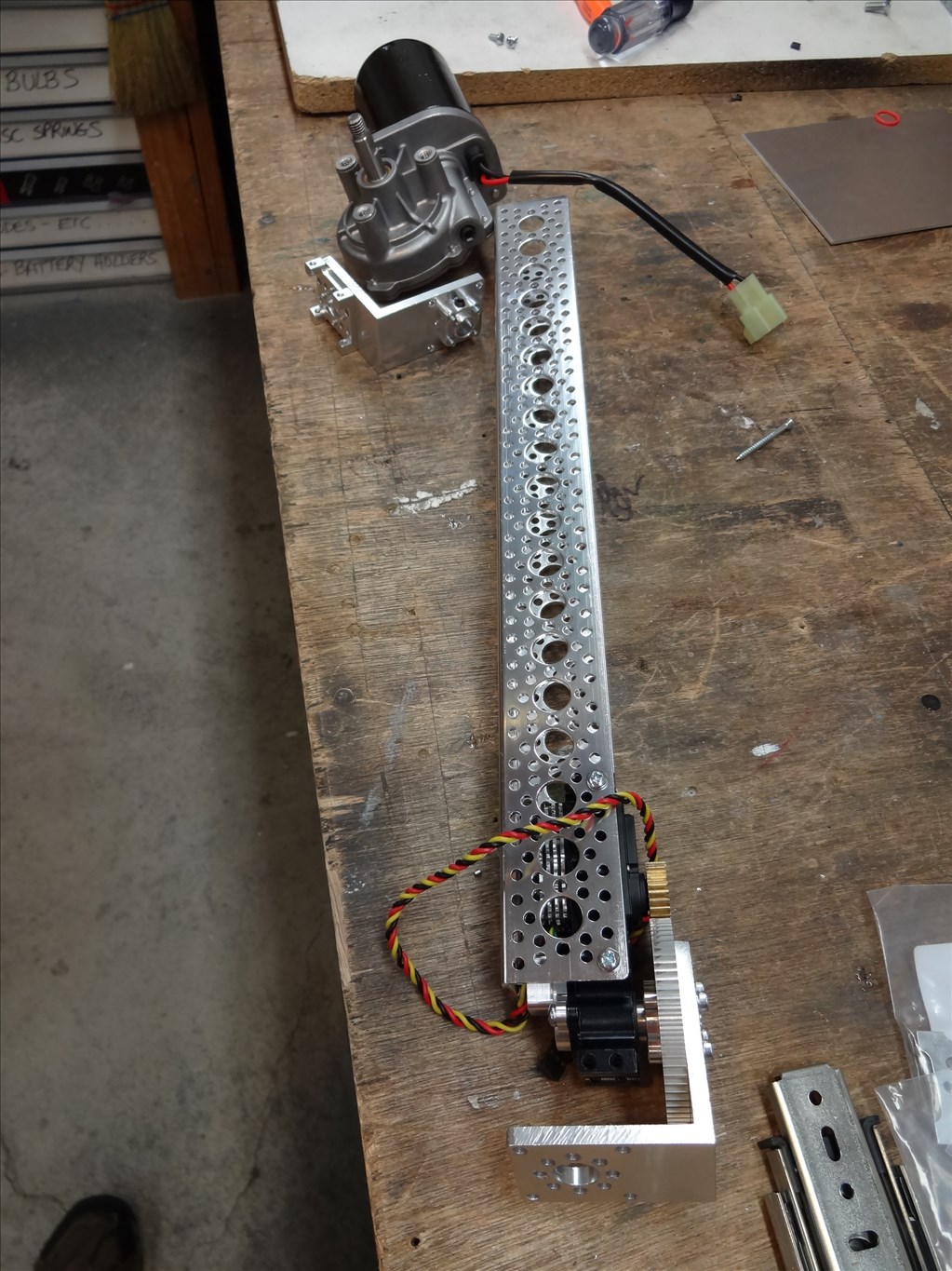
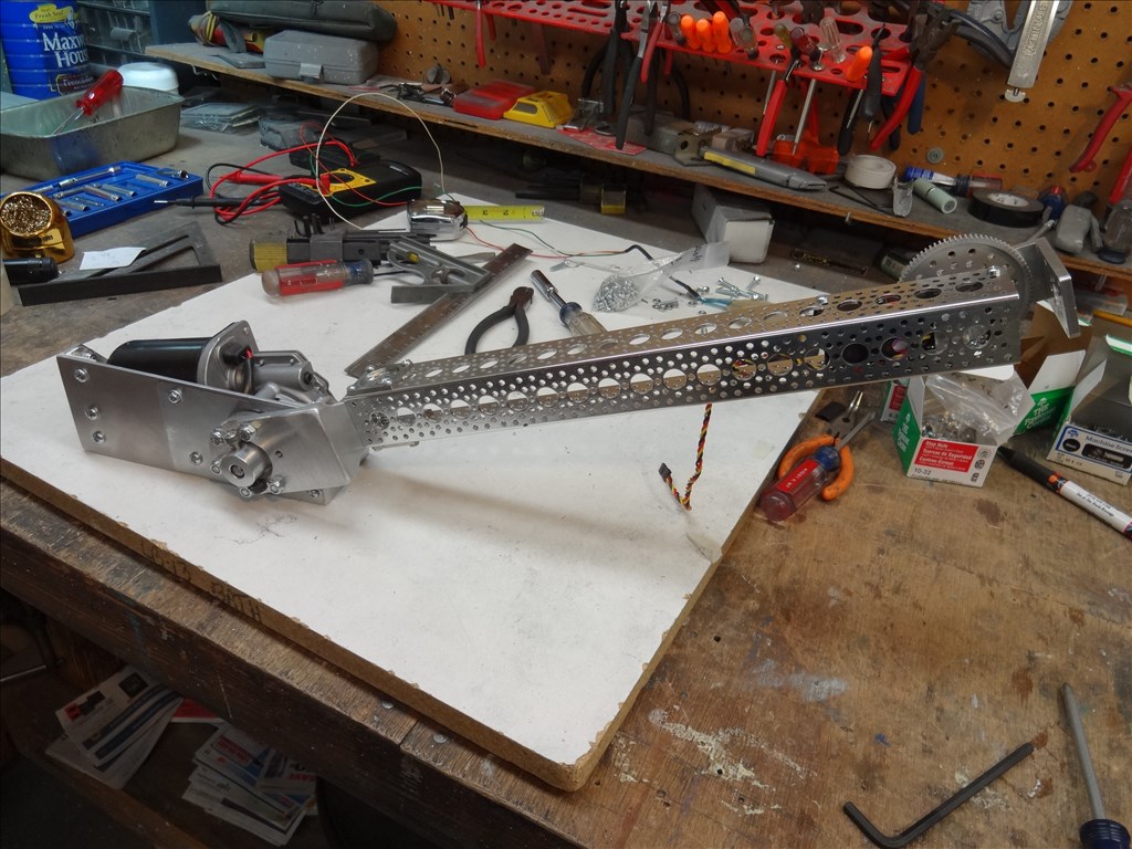
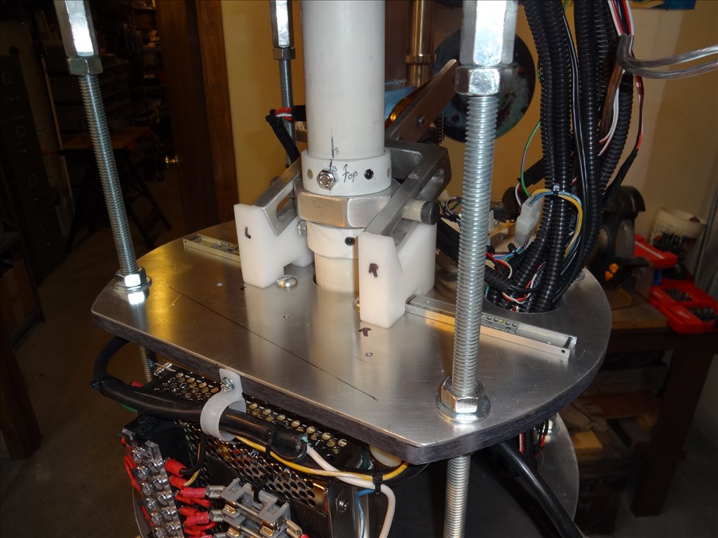
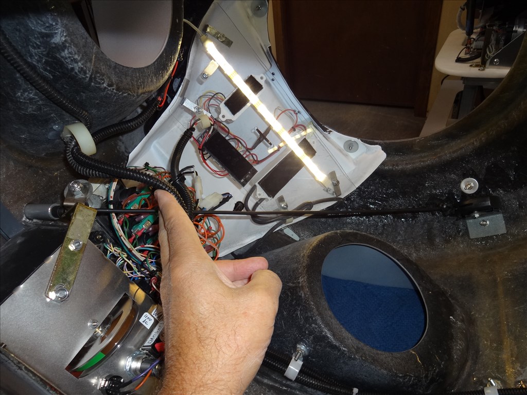
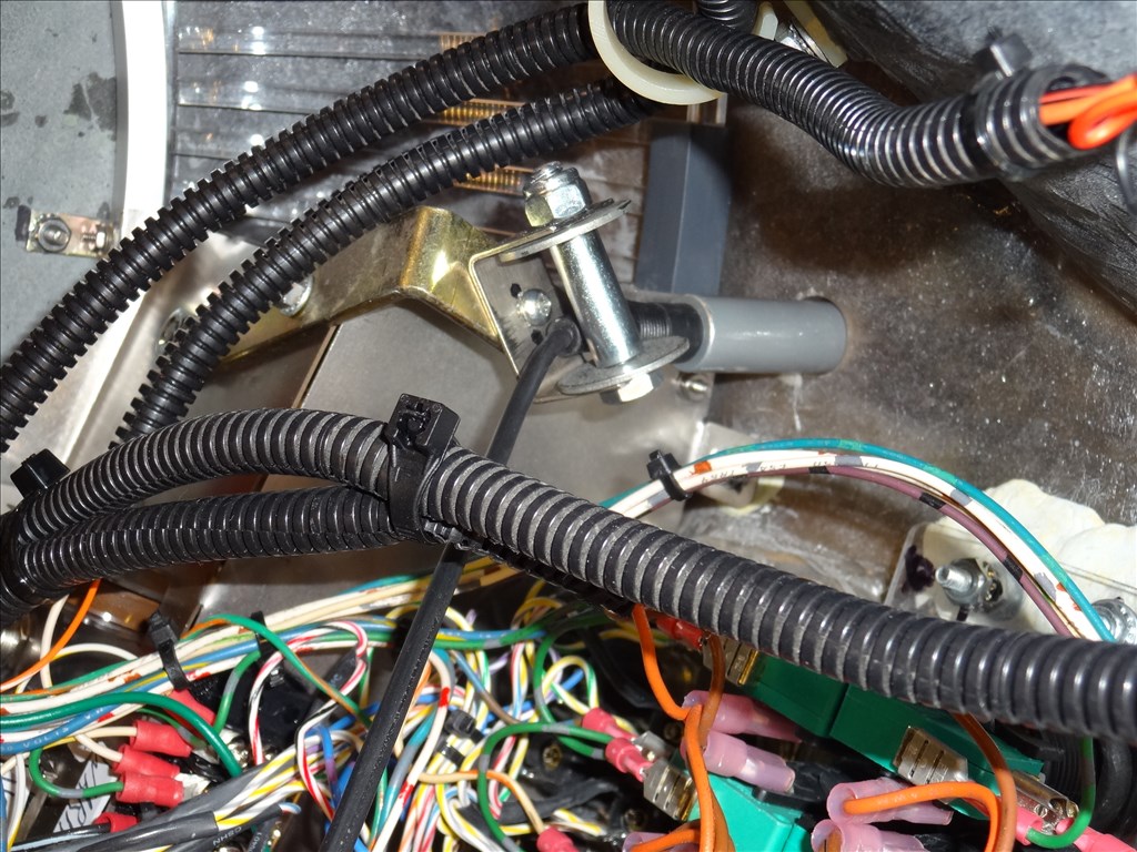
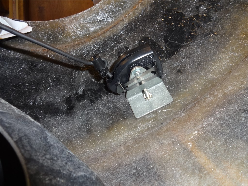
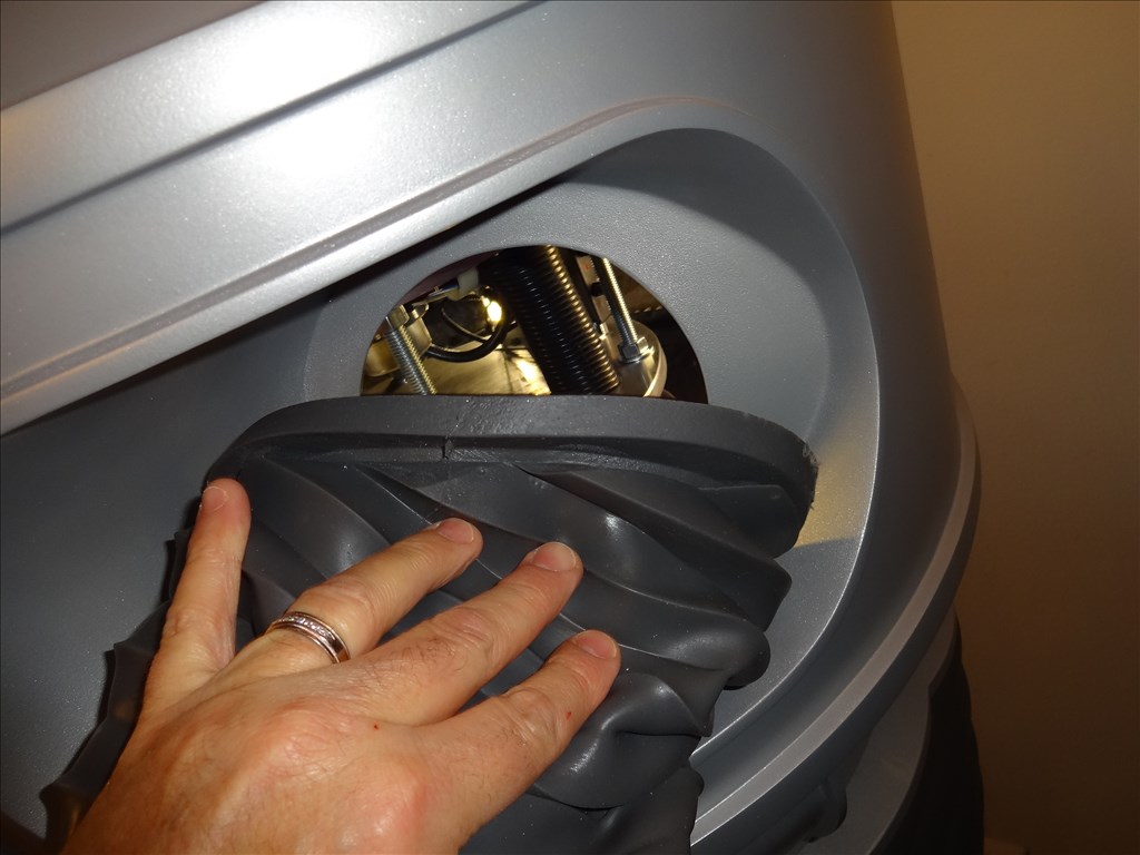
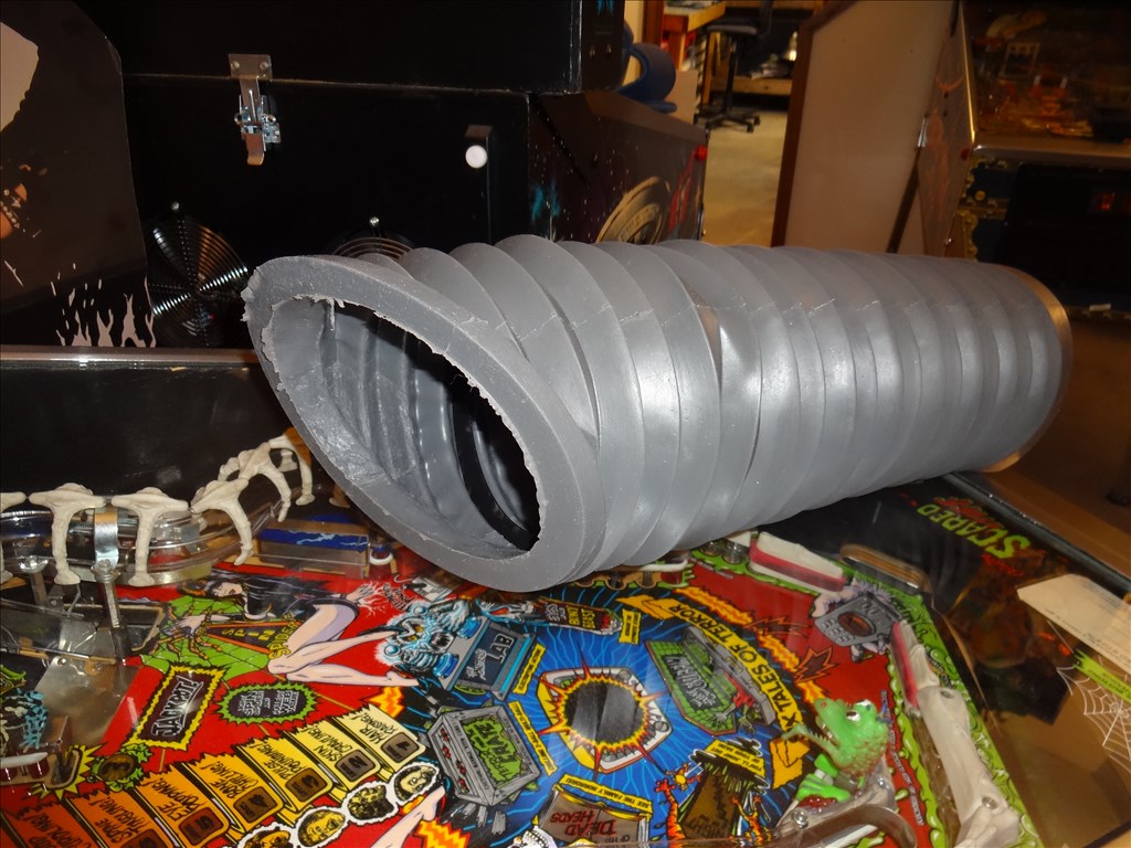
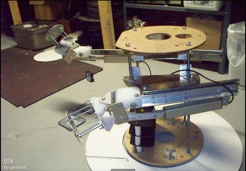
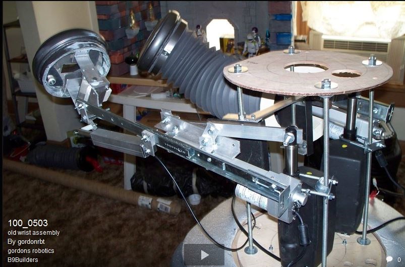
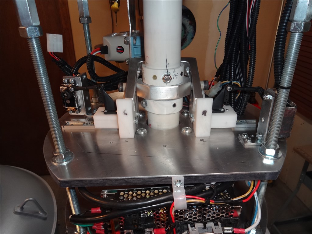
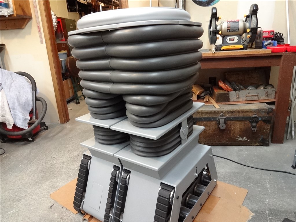
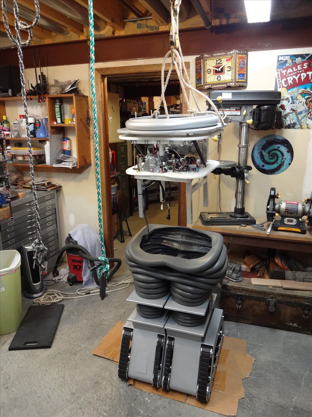
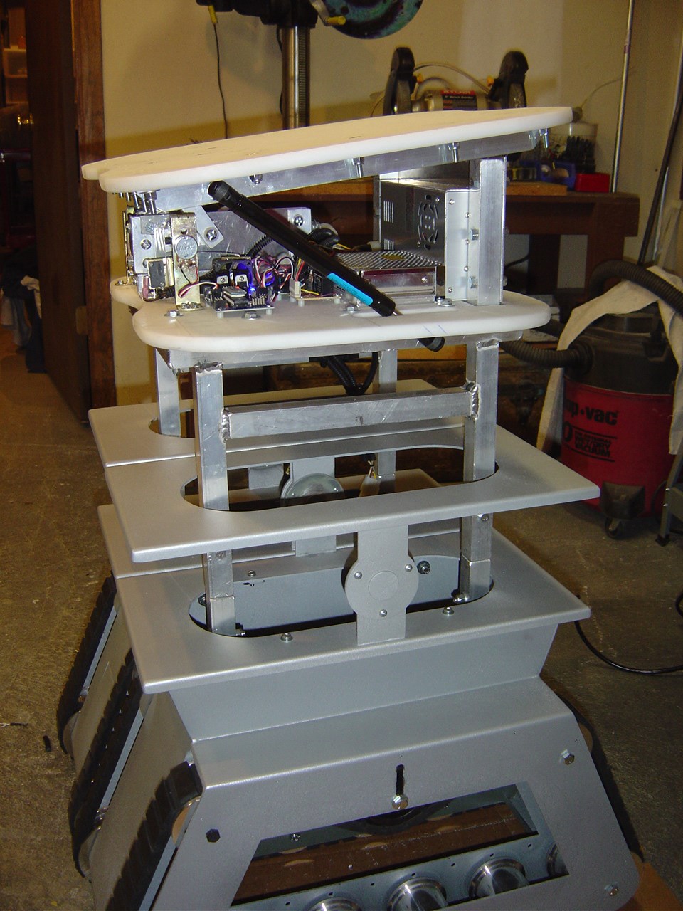
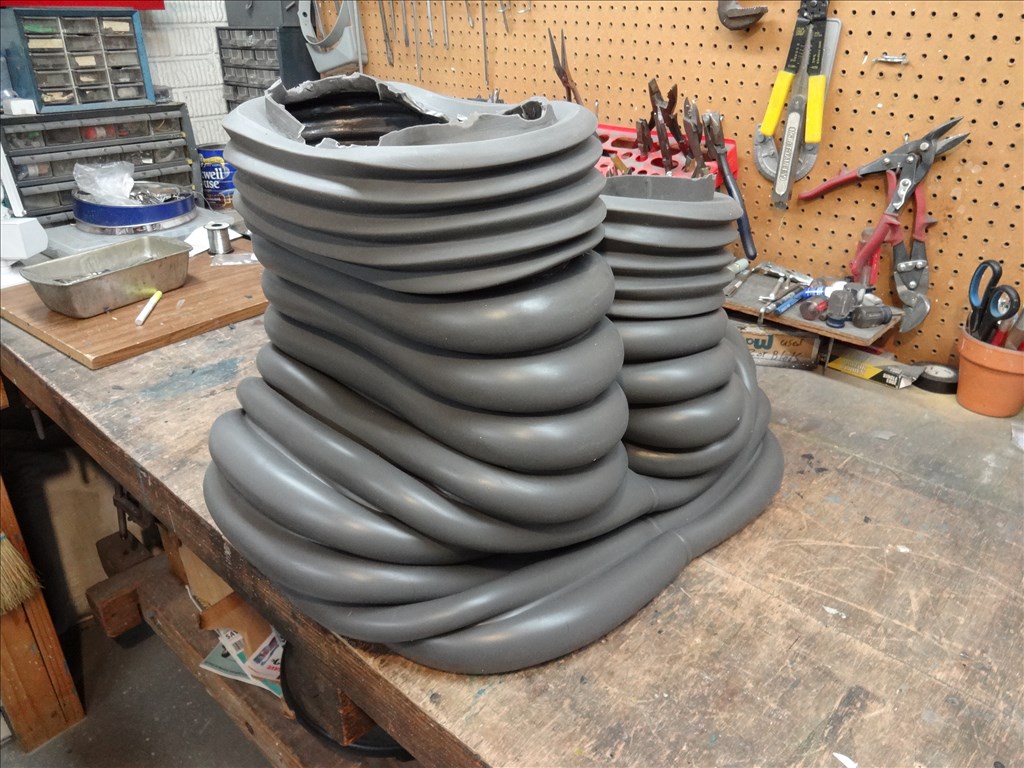
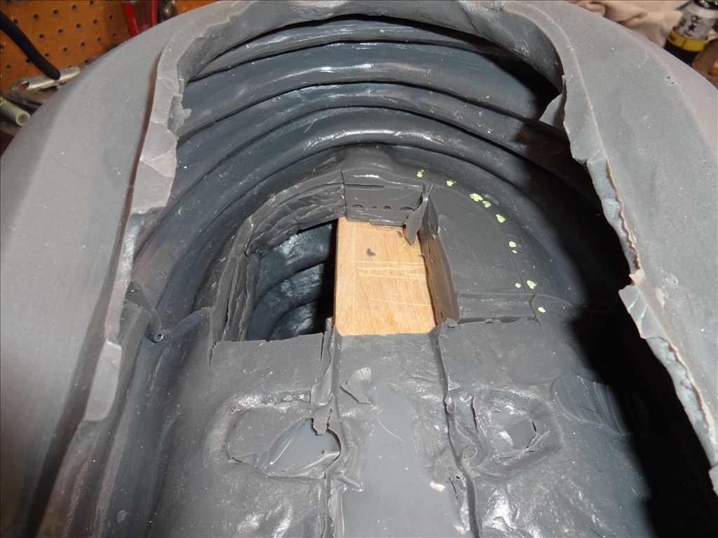
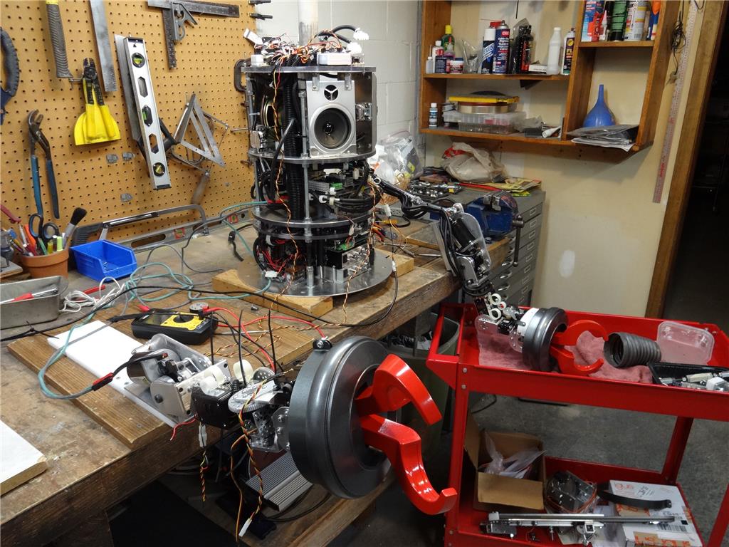
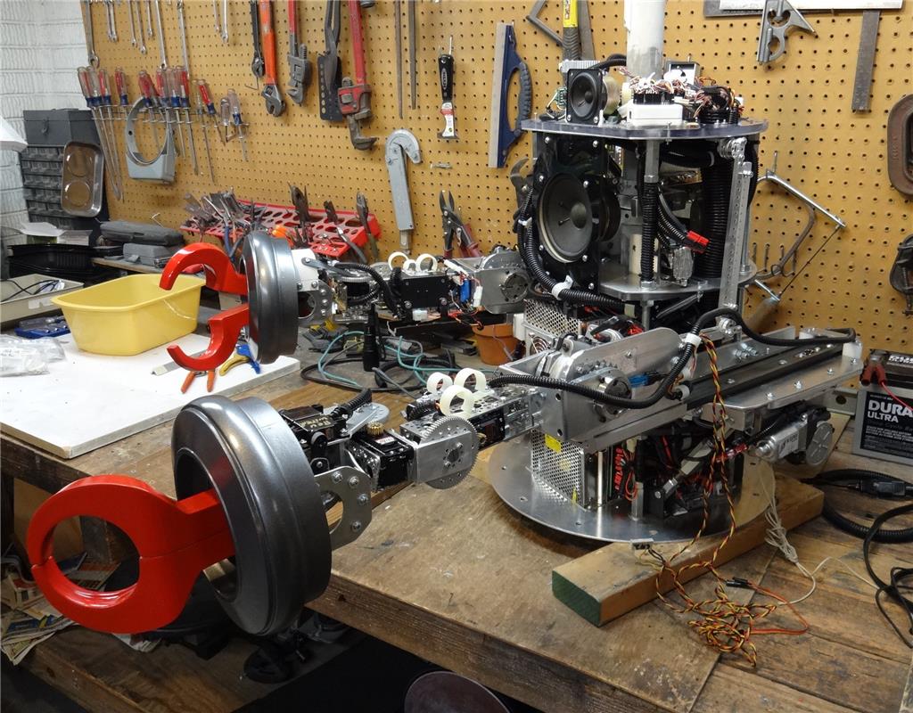
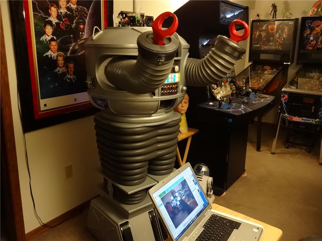
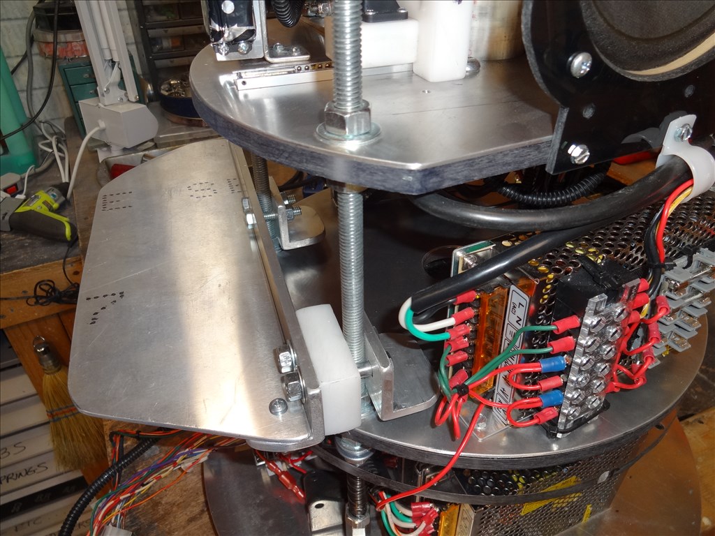
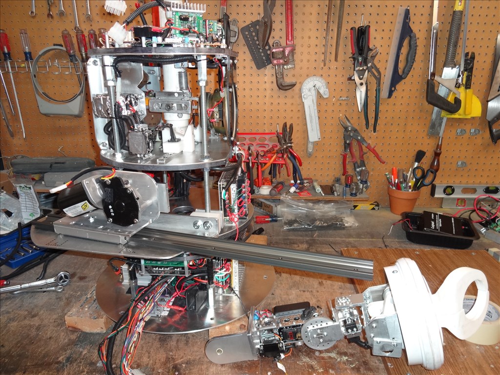
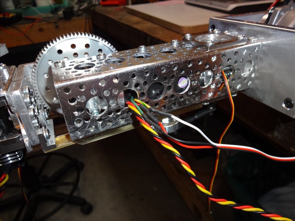
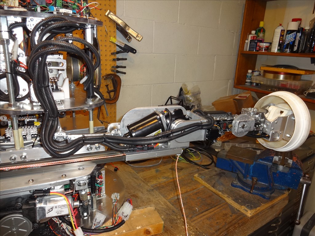
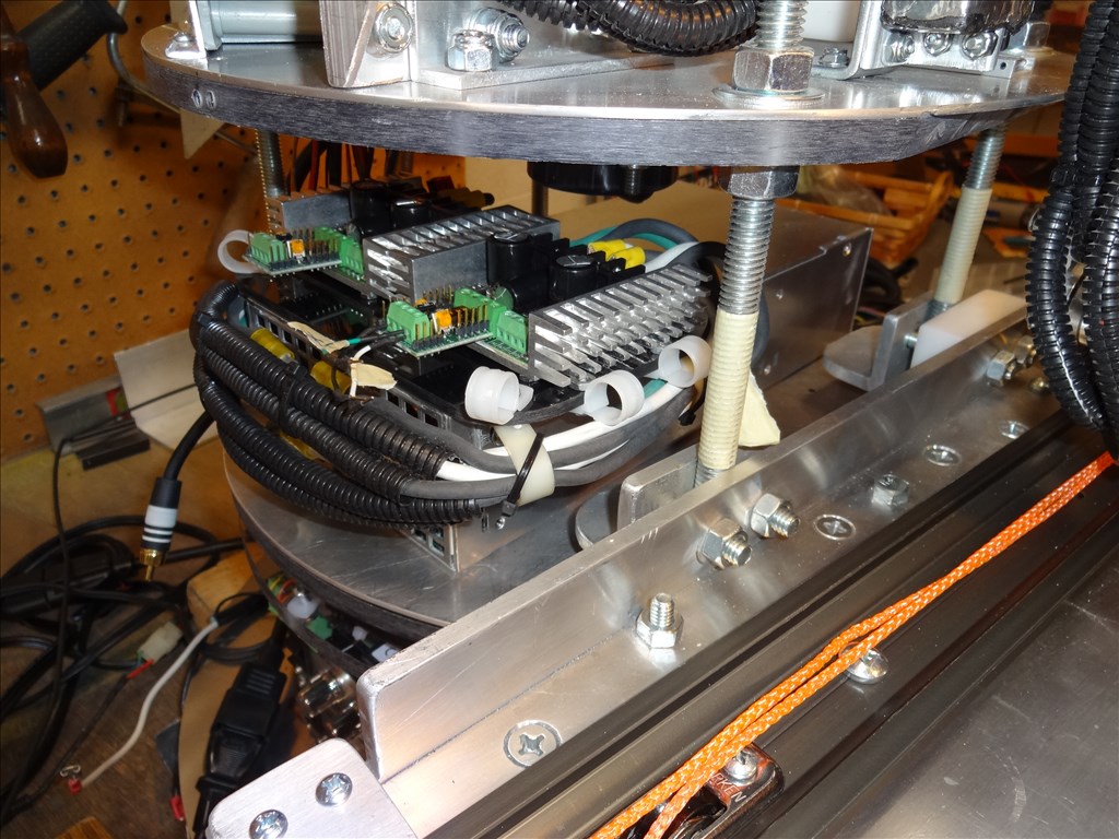
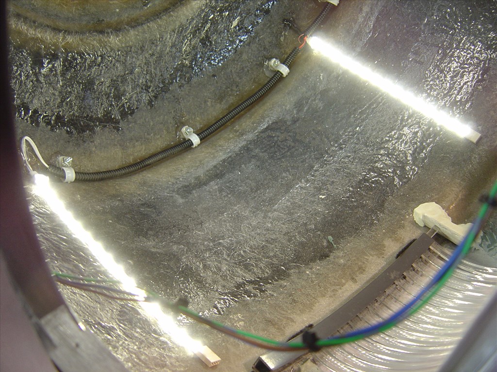
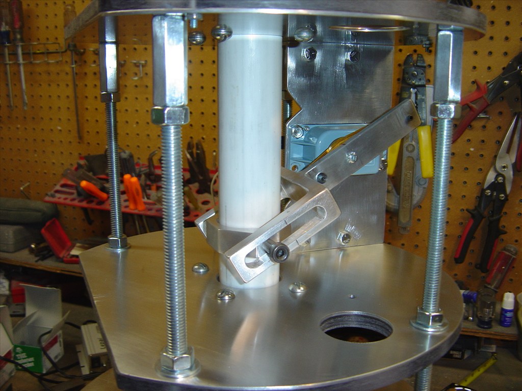
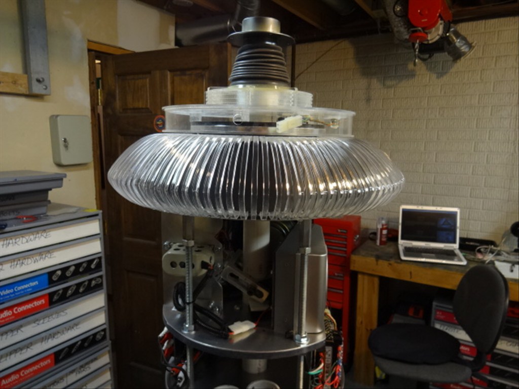
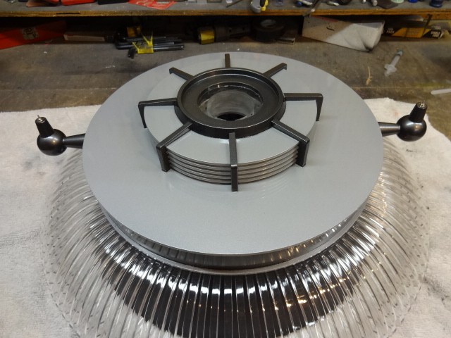
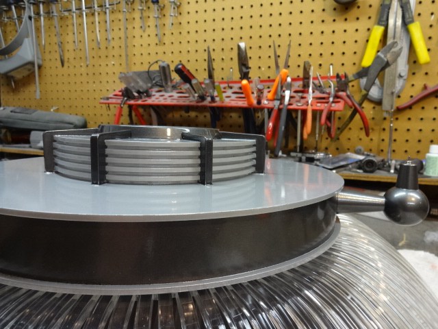
Last month I got my shelf mounted on the CSS for the arm delivery rail system that will move my B9 arm in and out of the torso. I've made slow progress and have now have got the rail system properly mounted and tuned to allow smooth operation and proper clearance through the arm hole and rubber arm skin.
A couple things I had to do was make an adjustable support system under the shelf and rework some possible structural problems with my robot frame. The added stress from the weight and movement of the new arms had me worried about his waist being too weak and adding too much stress in the wrong places.
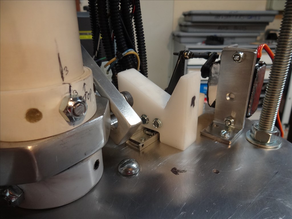
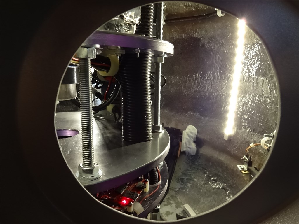
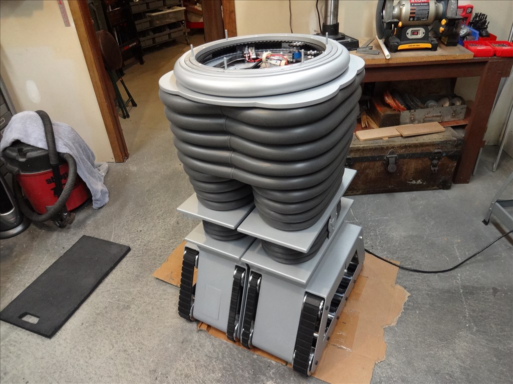
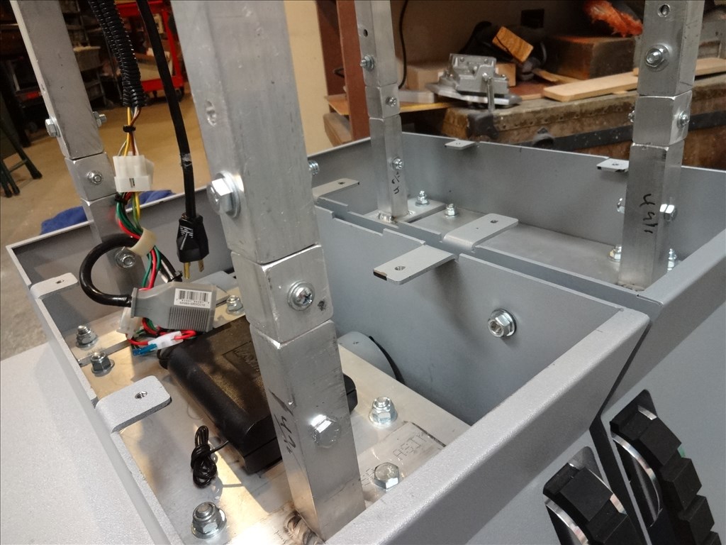
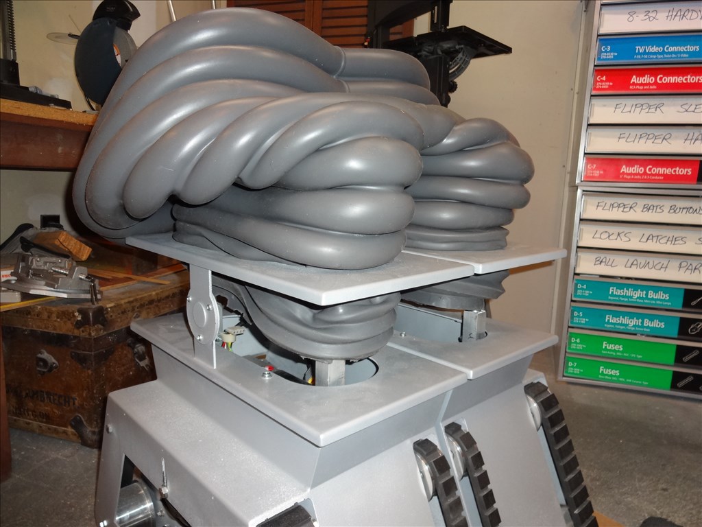
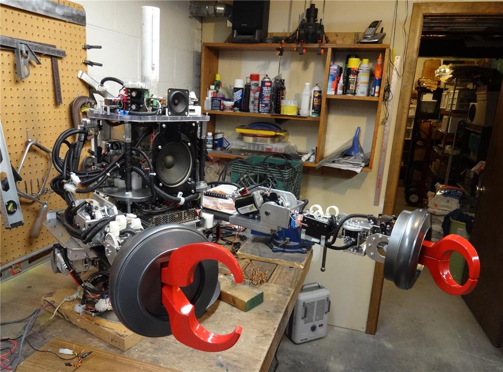
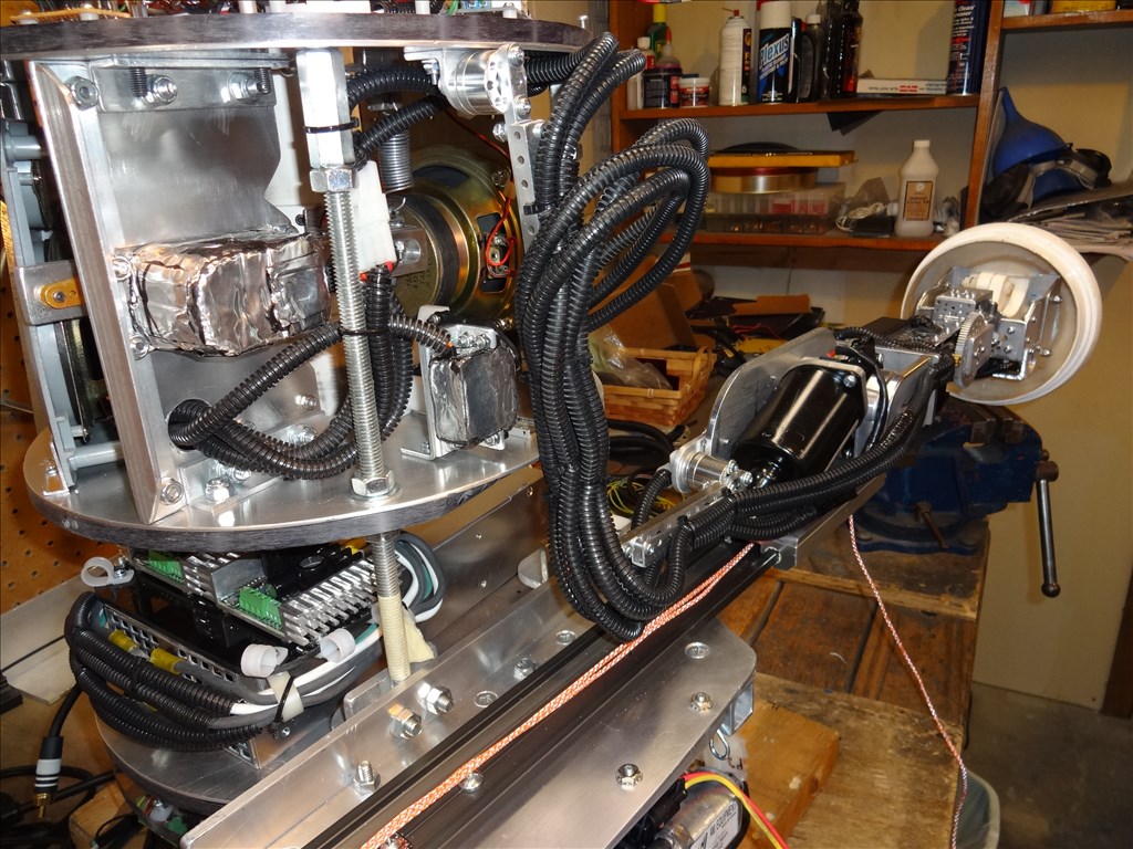
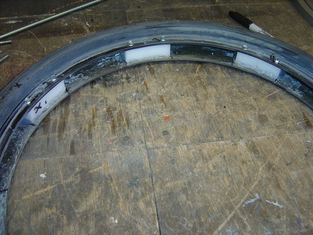
For the adjustable supports I simply got some right hand and left hand 3/8th threaded rod, left and right hand threaded couplings & nuts and a cool little peace of hardware called a sleeve nut. A Sleeve nut has right and left hand threads on each side and can fasten parts with right-hand threads to parts with left-hand threads. Man, that's a lot of right and left threads. Anyway, when placed together properly they make a cool little turnbuckle. I fastened this below the rail shelf and using the sleeve nut I can adjust the height of the outer edge of the shelf and fine tune it's position and tension. My original intention was to keep as much stress off the fiberglass B9 torso as possible and place the stress on the CSS (central Support and storage System). So I angled the turnbuckle supports into the base of the CSS.
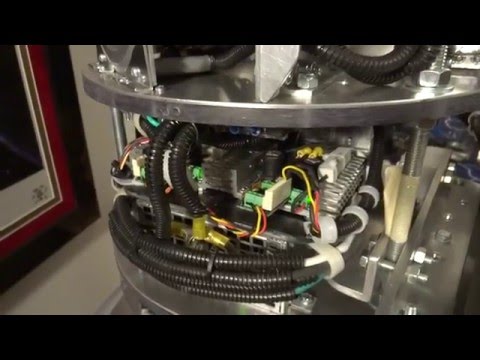
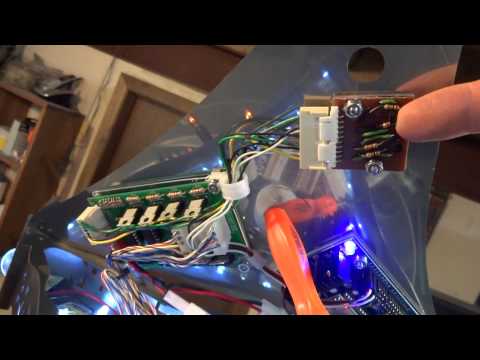
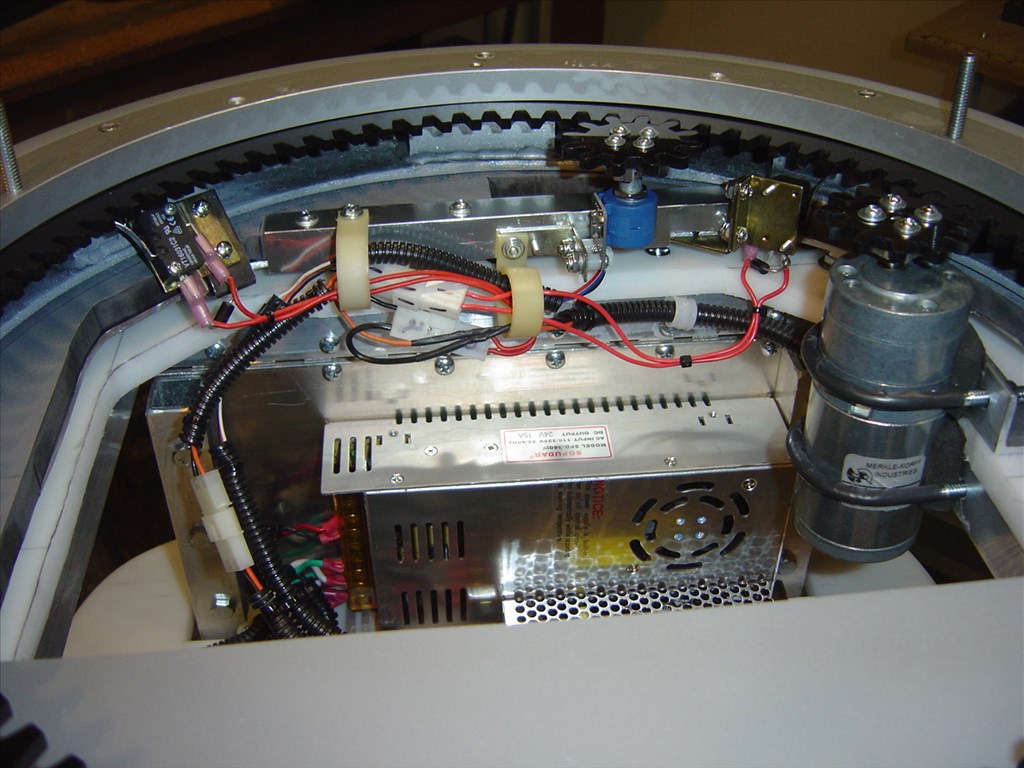
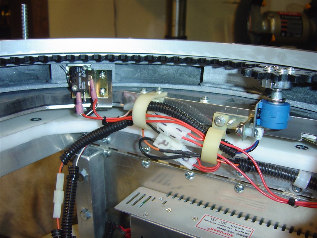
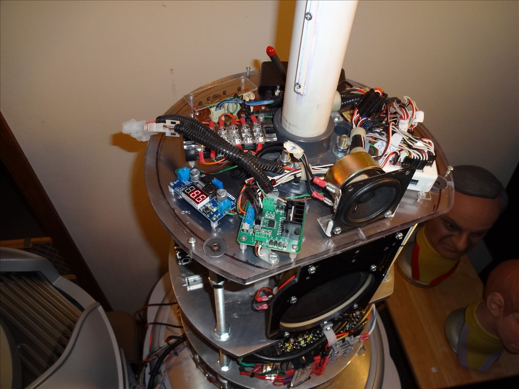
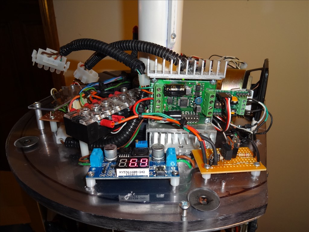
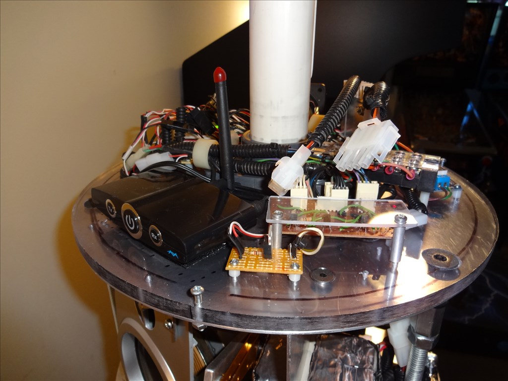
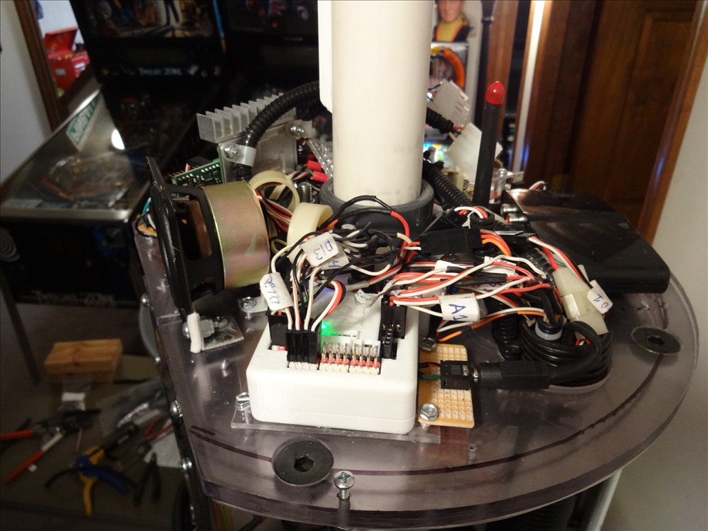
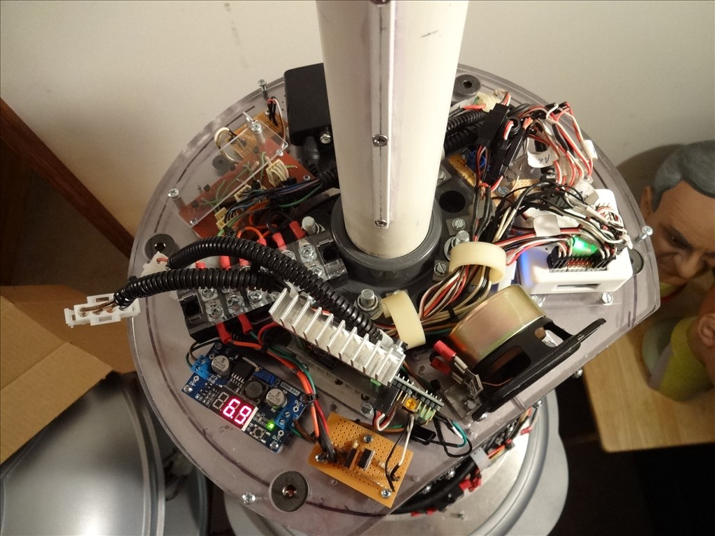
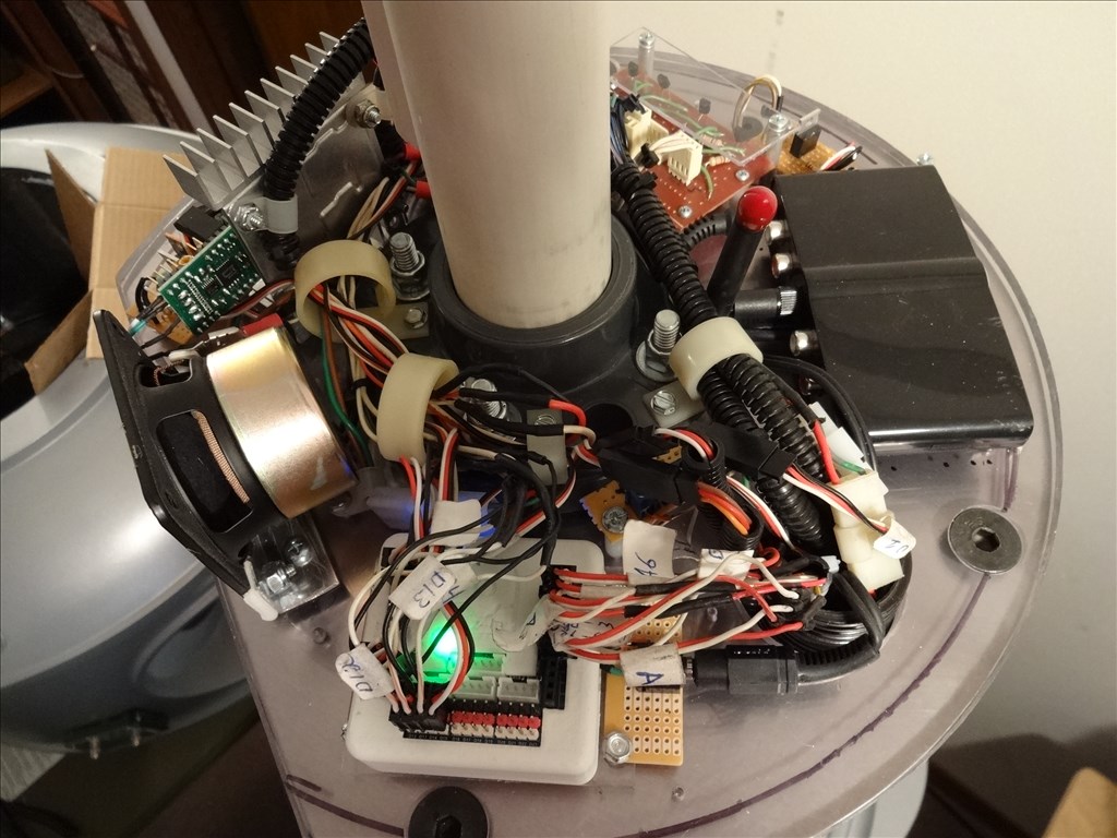
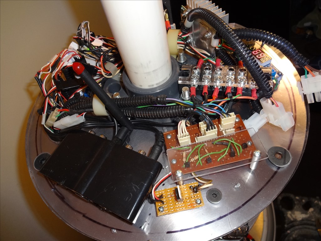
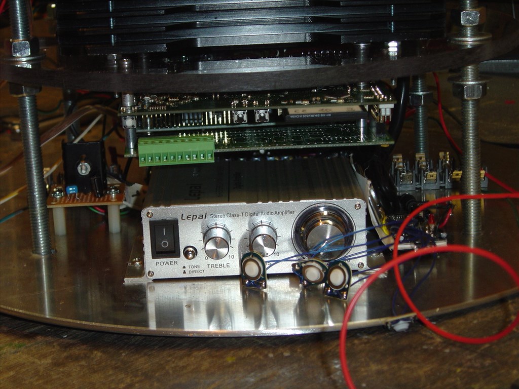
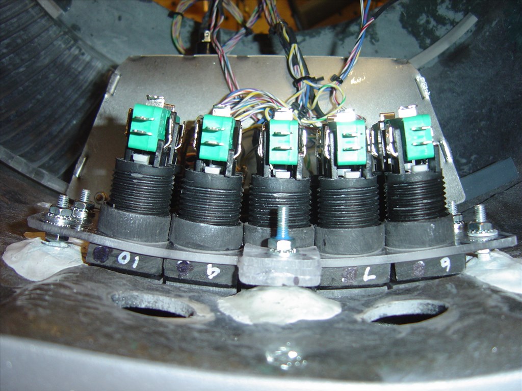
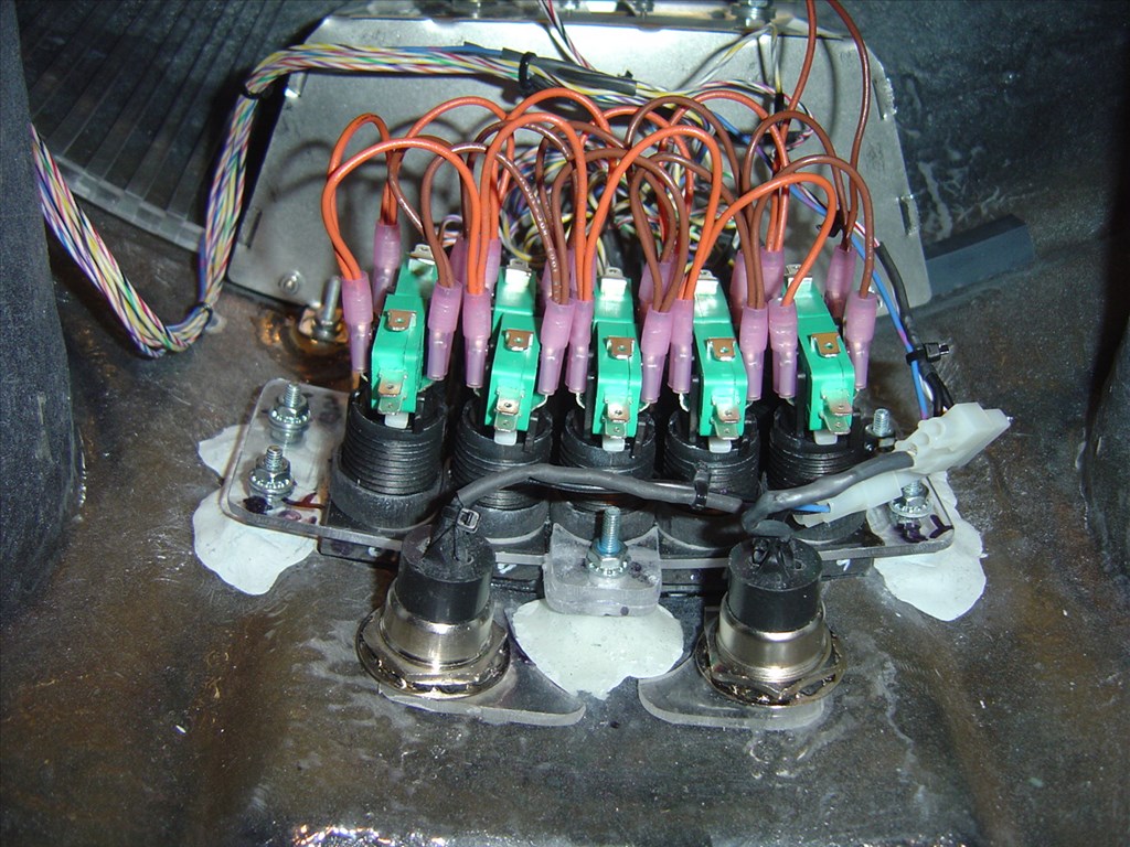
Having to mount the base of the supports to the base of the CSS caused me to have to move around a lot of electronic and sound components around that I had already thought mounted and complete. Actually it's a good thing because I was able to clean up some messy wiring and bad device placements. After building and adding things for three years now I'd started to just stick things and add wires where there was room and not where they "should go". Anyway, it gave me a good excuse to redo some of that mess.
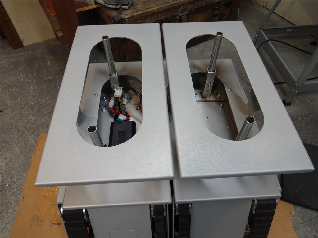
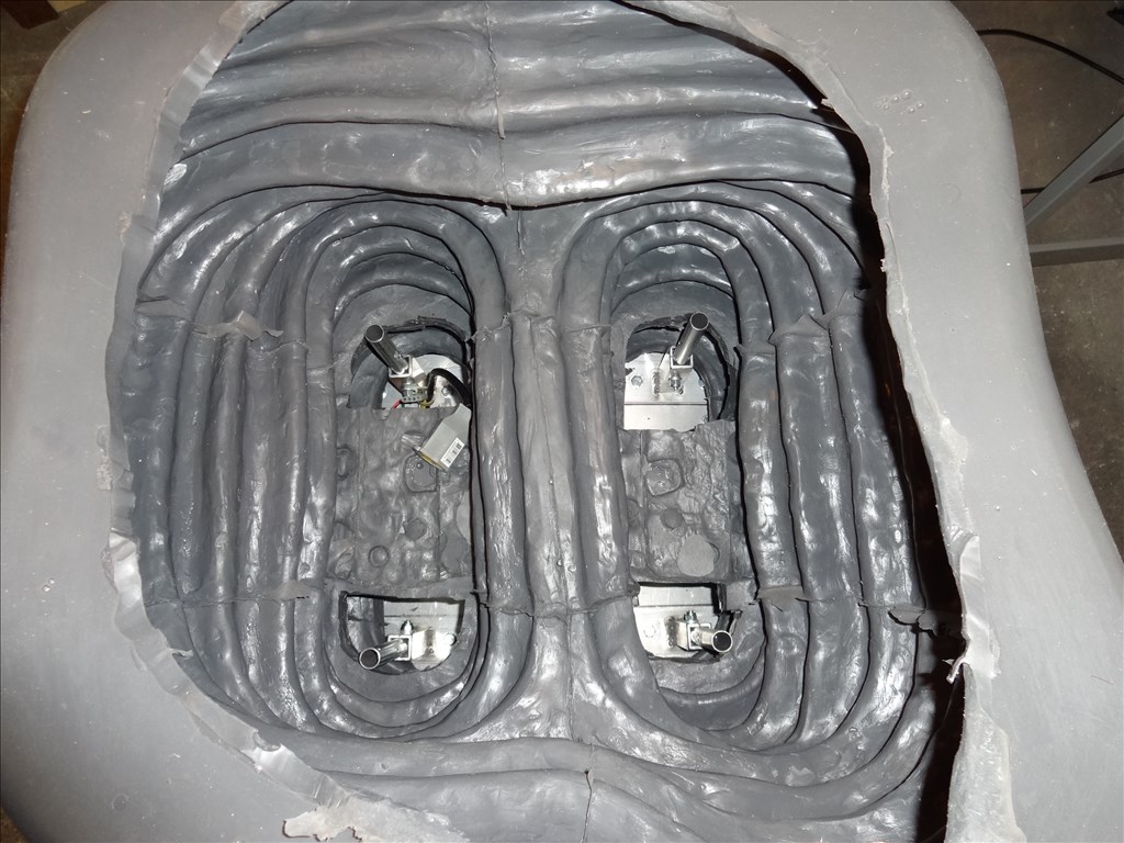
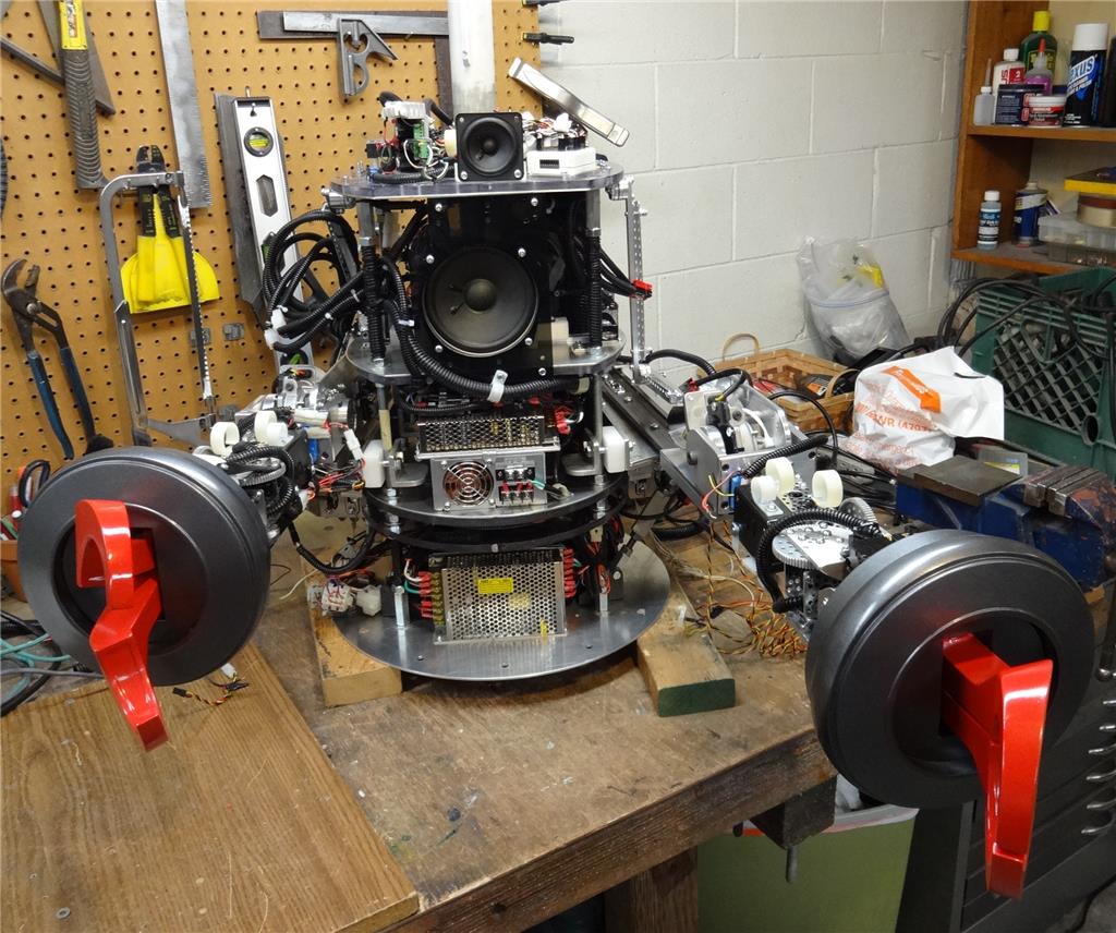
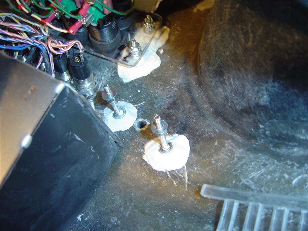
The other thing I needed to to was add some more attachment bolts to the Lazy Susan that the CSS and Torso attaches to. If you can follow my rambling: With the addition of over 25lbs of arms that will stick out in front of the robot when extended I needed to make sure that stress was flowing down through the CSS, through the Lazy Susan and down into the leg support system. Before my modification the nuts that held down my torso and CSS were on the same bolt. I didn't like the fiberglass base if the torso being sandwiched between that stress. I added 4 more bolts to the Lazy Susan and cut holes larger then the nuts in the bottom of the torso where these were located. This way I can lock down the CSS to the Lazy Susan with it's own set of nuts. The torso base will slip down over those bolts and nuts and the original bolts & nuts will hold that down. Now the stress will go through the new CSS lock down nuts and bolts and not the torso lock down nuts & bolts. Hows that for confusing? confused Sorry. On my next video I make I'll try to show this.
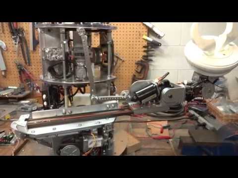
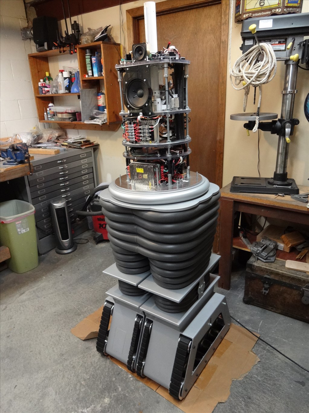
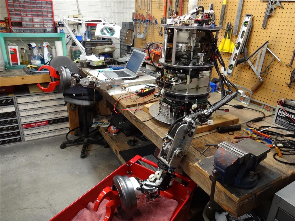
So before I took it all apart again for my next step of adding the drive train and motor to move the arm in and out of the torso I made a video of my progress so far. Hopefully you'll enjoy this and it will explain some of what I was mumbling about above:
Nice update Dave, and I'm glad your making progress. It sounds like you have things sorted with the additional weight now and the only way is forwards now. Wow, 3 years, the B9 project surely is a labour of love and the work you are putting in to this shows that.
Keep it up my friend, and look forward to your progress.
Steve.
EDIT:
Great video as well. Thanks for taking the time to shoot it.
Thanks Steve for the kind words. Yep, it's been a long road and sometimes it's hard to keep going. Even more so now that it's a nice hot summer and lots of other fun stuff to do. However, your right, it's a labor of love and I'm slowly fulfilling a childhood dream.
Thanks for mentioning the Vid wasn't working. I had forgot to hit the Publish button. It should work now.
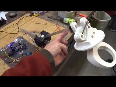
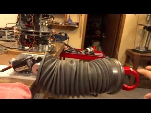
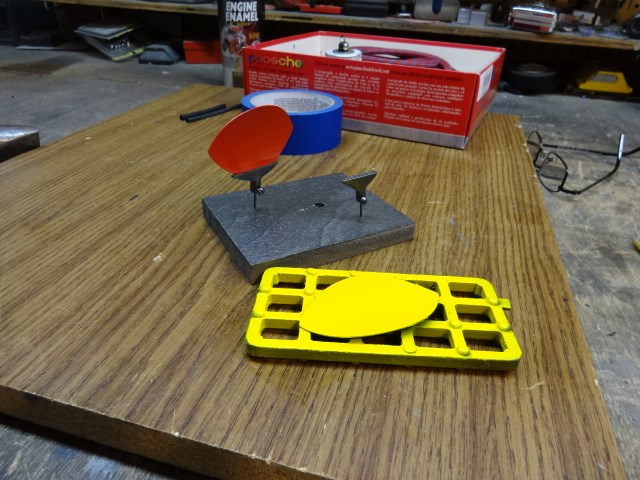
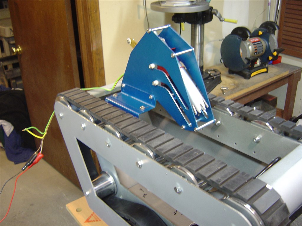
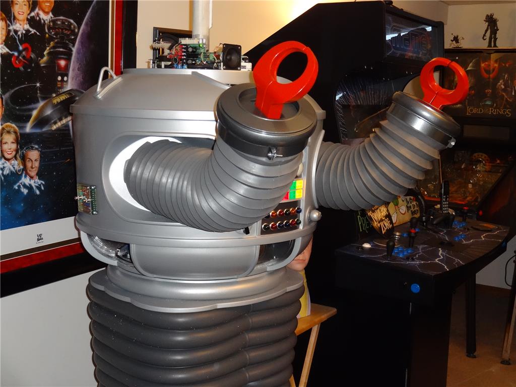
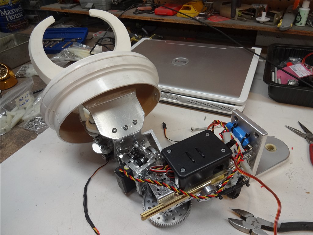
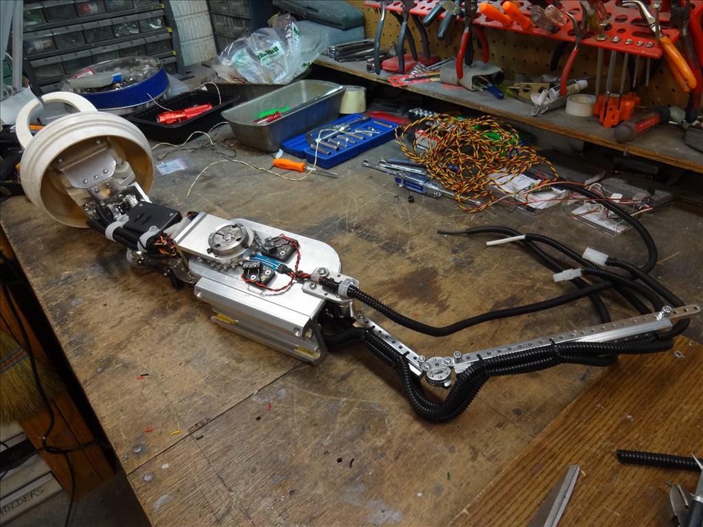
Dave, that is the most beautifully designed arm I have ever seen! Almost a shame to cover it with the rubber skin.... Just goes to show what blood, sweat, t(g)ears and determination can do. I truly admire your work and skills. This is true robot building at its maximum potential!
I have some questions and requests for ya:
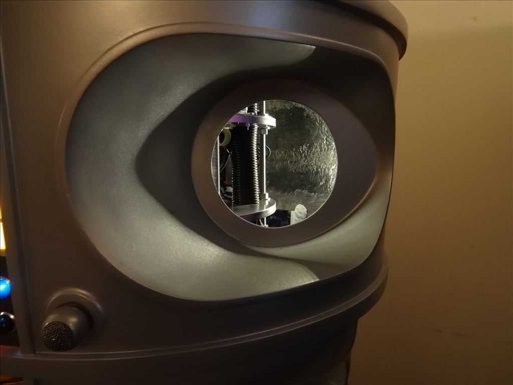
How are you going to be able to remove the torso once the arm is attached? I have never seen how the torso goes together or comes apart. In other words how in the world do you get in there to do any work inside? Can you provide some video of this when you get the chance?
Also, can you provide the websites and part numbers for the following: -The power window motors you showed in the video -The rail slides you mentioned for extending the arms -Your source for the Molex connectors, pins and pin crimper that you use.
Thanks in advance! But, hey, seriously, I don't want to interfere with your work, so no pressure my friend.
Rex
Looking great!
Dave, amazing work as always! Can I ask how did you get the custom phrases that absolutely sound like Dick Tufeld the B9 original voice?
Tony
Thanks for all the encouraging praise. It's good to get some feedback. I'm always open to ideas and suggestions. Please don't hesitate to offer feedback (even if it's critical). I'm a true believer in listening to others input to make things better.
@Tony, LOL, the reason the sound clips sound like Dick Tufeld is because it's him. For years before he died the B9 Builders club had a close relationship with him. The enlisted his talent to do hundreds of voice clips for the club and it's members. There is even CD software called I-B9 that has an interface to play hundreds of included mastered custom recorded voice clips from your laptop. Here's the link if anyone is interested in getting one. Scroll down the parts page and you'll find it :
Craig Reinbrecht's I-B9 CD
There is also another CD out there called Robot Ramblings with hundreds more remastered cuts from the TV show but it's getting hard to get. It has the background sounds and music cut out of each phrase and sounds real good. I dont know if this CD is still available but here's a link to the web page selling it:
Dan Monroe's Robot Ramblings
For years before he died the B9 Builders club had a close relationship with him. The enlisted his talent to do hundreds of voice clips for the club and it's members. There is even CD software called I-B9 that has an interface to play hundreds of included mastered custom recorded voice clips from your laptop. Here's the link if anyone is interested in getting one. Scroll down the parts page and you'll find it :
Craig Reinbrecht's I-B9 CD
There is also another CD out there called Robot Ramblings with hundreds more remastered cuts from the TV show but it's getting hard to get. It has the background sounds and music cut out of each phrase and sounds real good. I dont know if this CD is still available but here's a link to the web page selling it:
Dan Monroe's Robot Ramblings
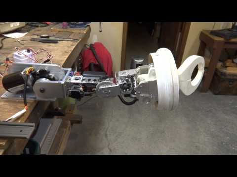
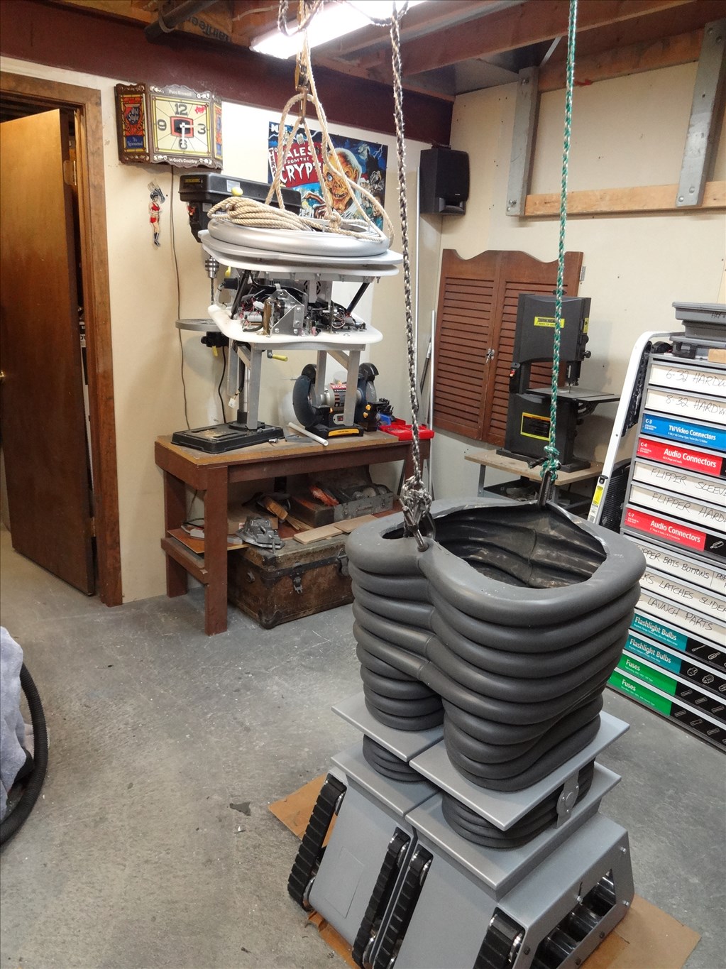
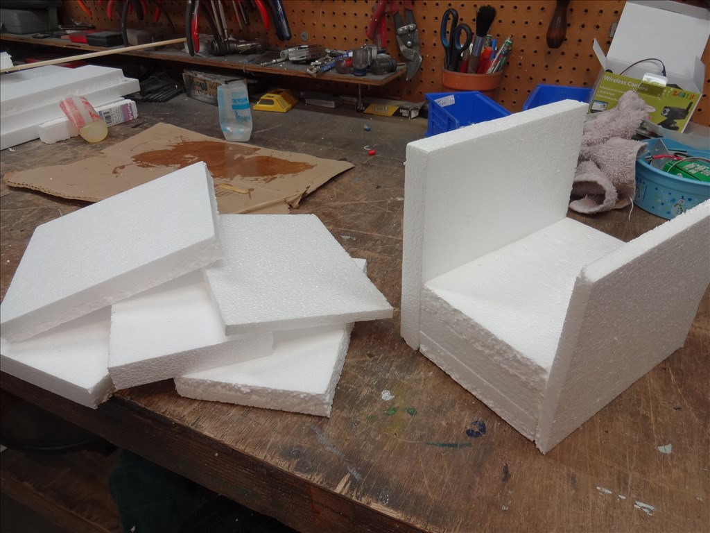
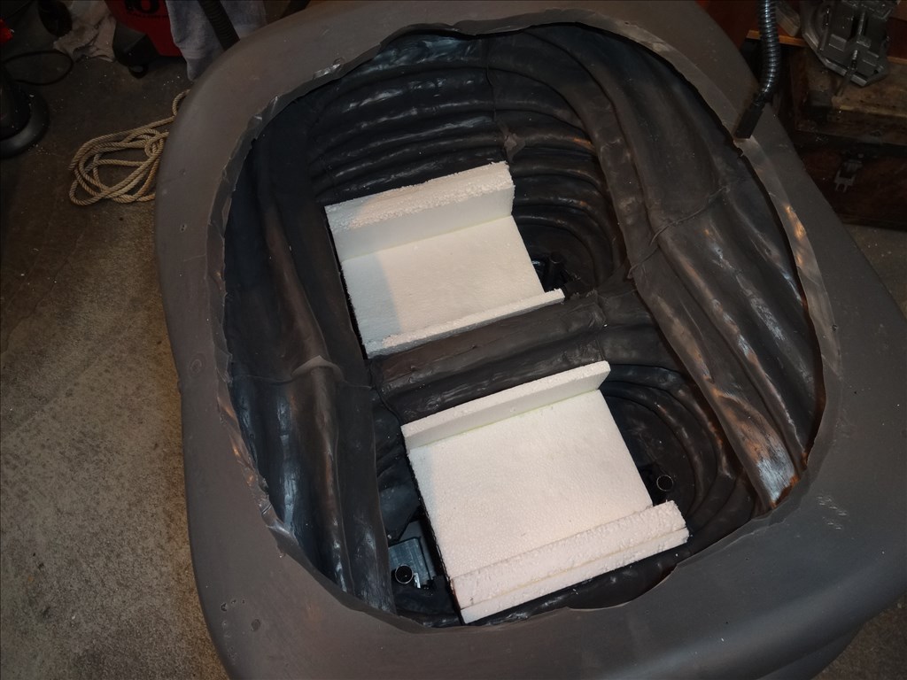
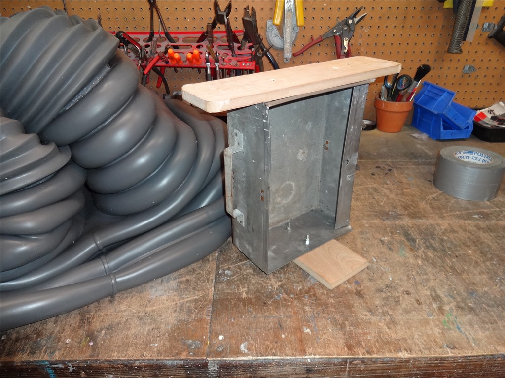
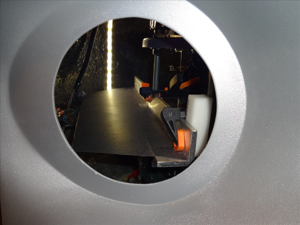
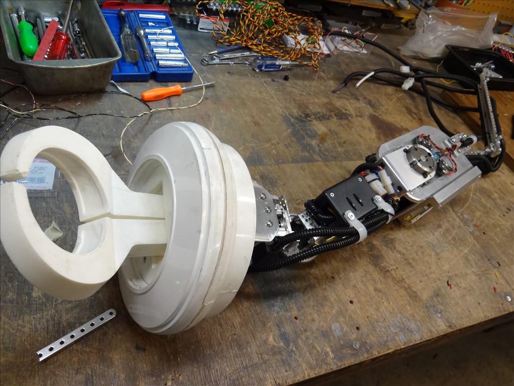
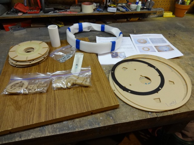
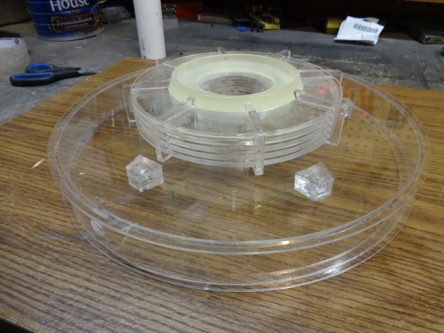
@Rex, Your too kind. Thanks for your complements. I'll be happy to give you all that info. "How do I take the torso off with that arm in place?" - Now that was the million dollar question and one that I struggled with for over a year. I needed to be able to install a functioning arm, attach it to the CSS and be able to remove it while working from outside the torso with it in place. All this while working through a 7" arm hole and the side and rear lower vents. There is no way to remove the torso while the arm is mounted on the robot and it's mounted to the CSS like I am doing. Then one day I saw a "Ship In a Bottle" and wondered how the hell they got that big thing in there through that little hole. This was exactly what I had to do to mount my B9 arms (however I do have the added advantage of the lower vents for access). I learned that the bottle ship builders put as much together outside the bottle that will fit through the hole and start building in a modular fashion from rear to front using tools that fit and reach. I knew I had to do the same thing to get my arm mounted and still be able to remove the torso. I built each part no bigger then the size of the arm or vent holes. Each section (like the shelf for example) is built to fit through the holes, mount or unbolt easily by reaching through the holes and by using just a couple simple box wrenches. The turnbuckle supports I custom built are held in place with pins and cotter pins. All I need to do to install or detach them from the shelf and CSS base is to simply unscrew the tension, unpin them and pull them out or out of the lower vents. What about the arm it's self? Once the power and control wiring is unplugged It simply slides straight out and off the front of the rails. Hope this is clear. You'll be able to see this all better in my next video where I'll have the torso off.
Here's the websites and part numbers for the following you asked for:
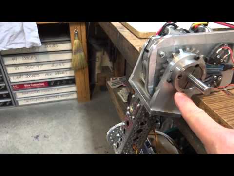
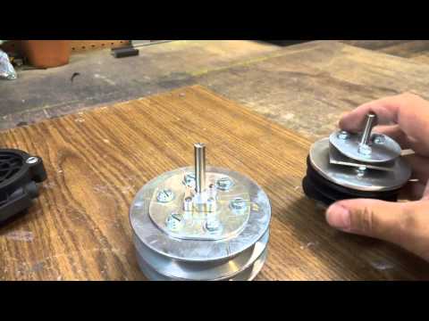
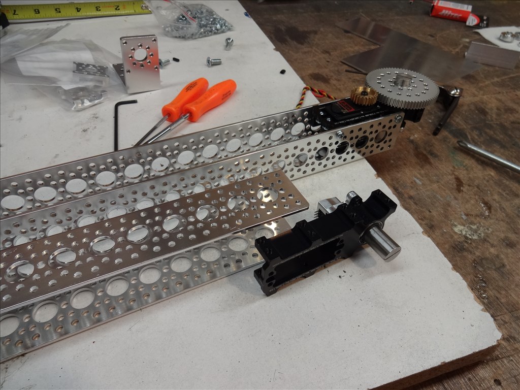
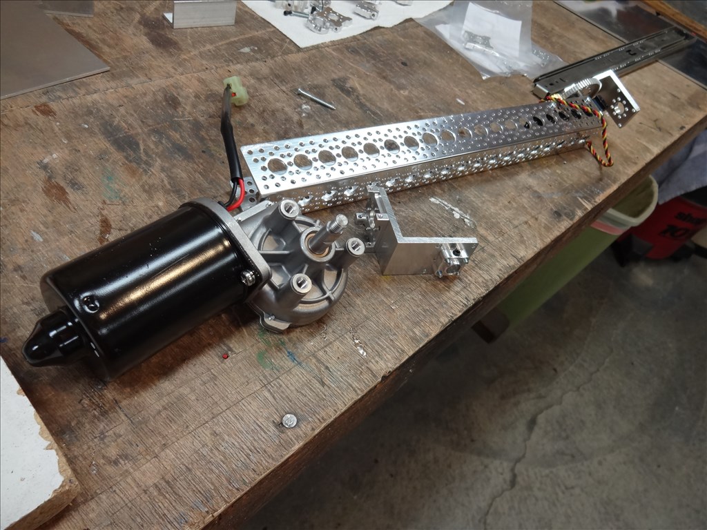
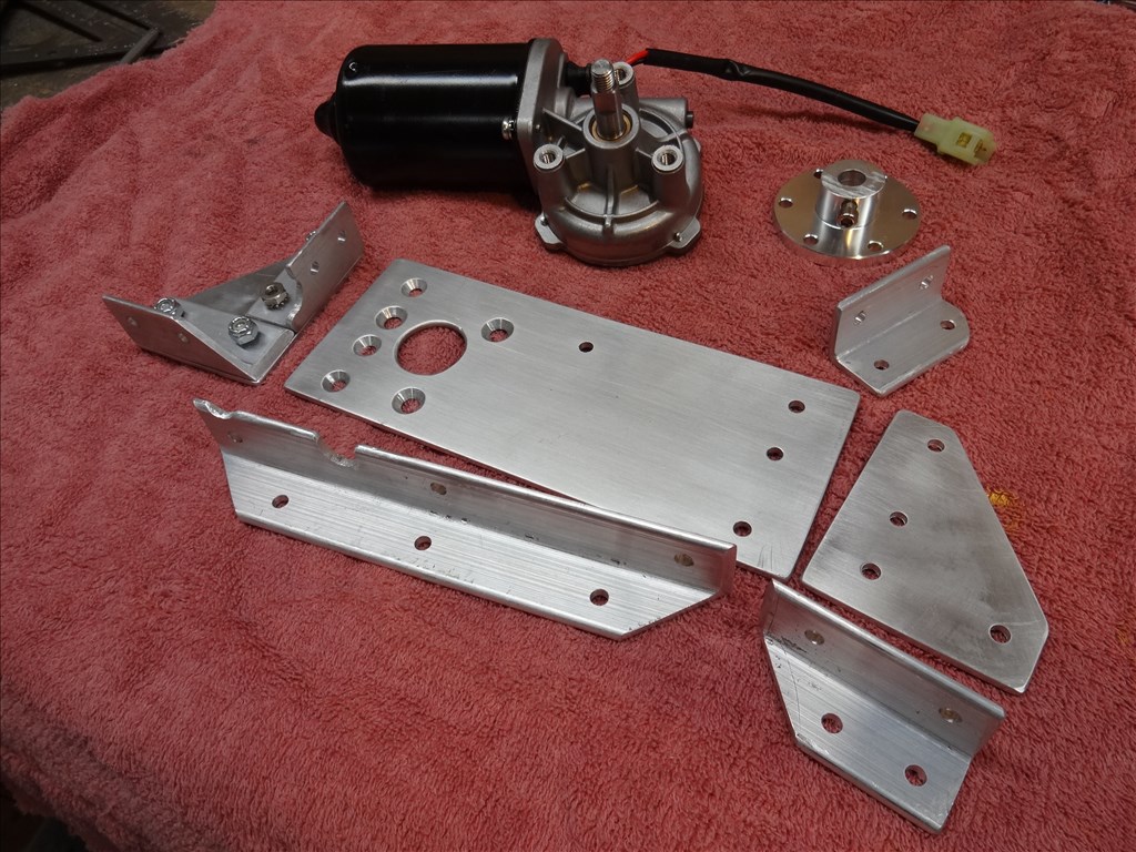
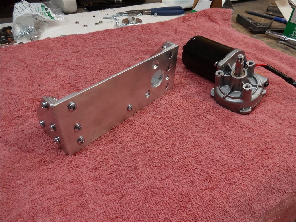
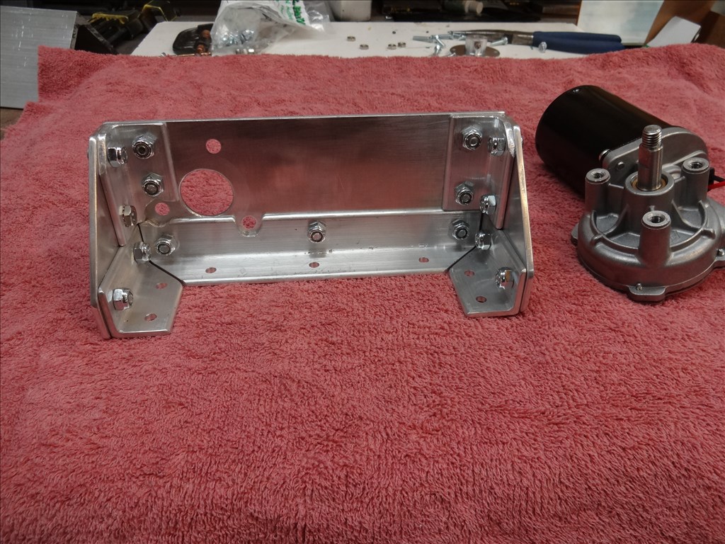
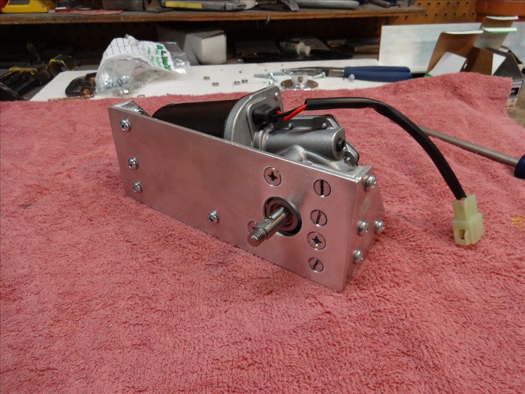
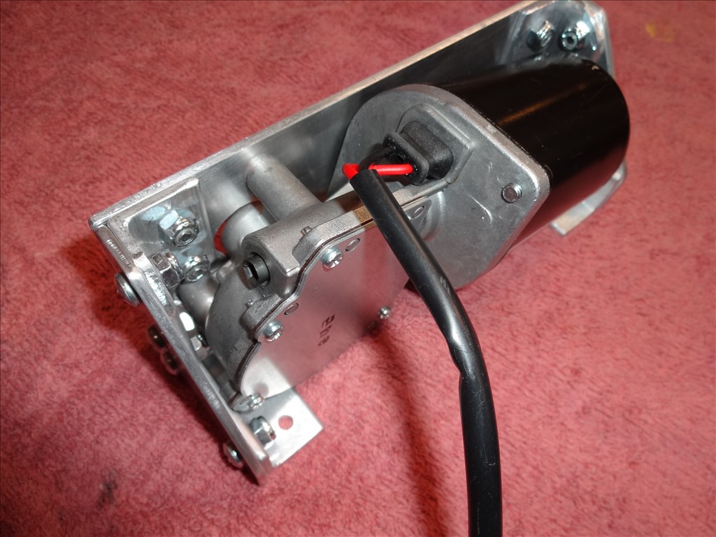
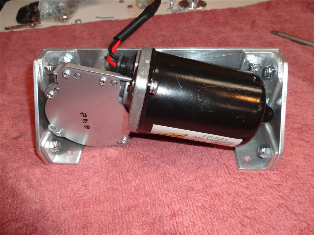
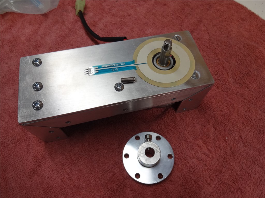
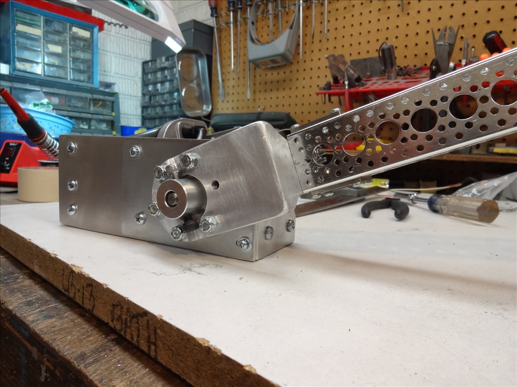
The Right and Left hand power window motors (I haven't tested these yet to see if they are strong enough but they should be): AME 210-series 12V 88in-lb Right-Hand gearmotor-shaft AME 210-series 12V 88in-lb Left-Hand gearmotor-shaft
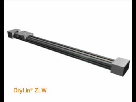
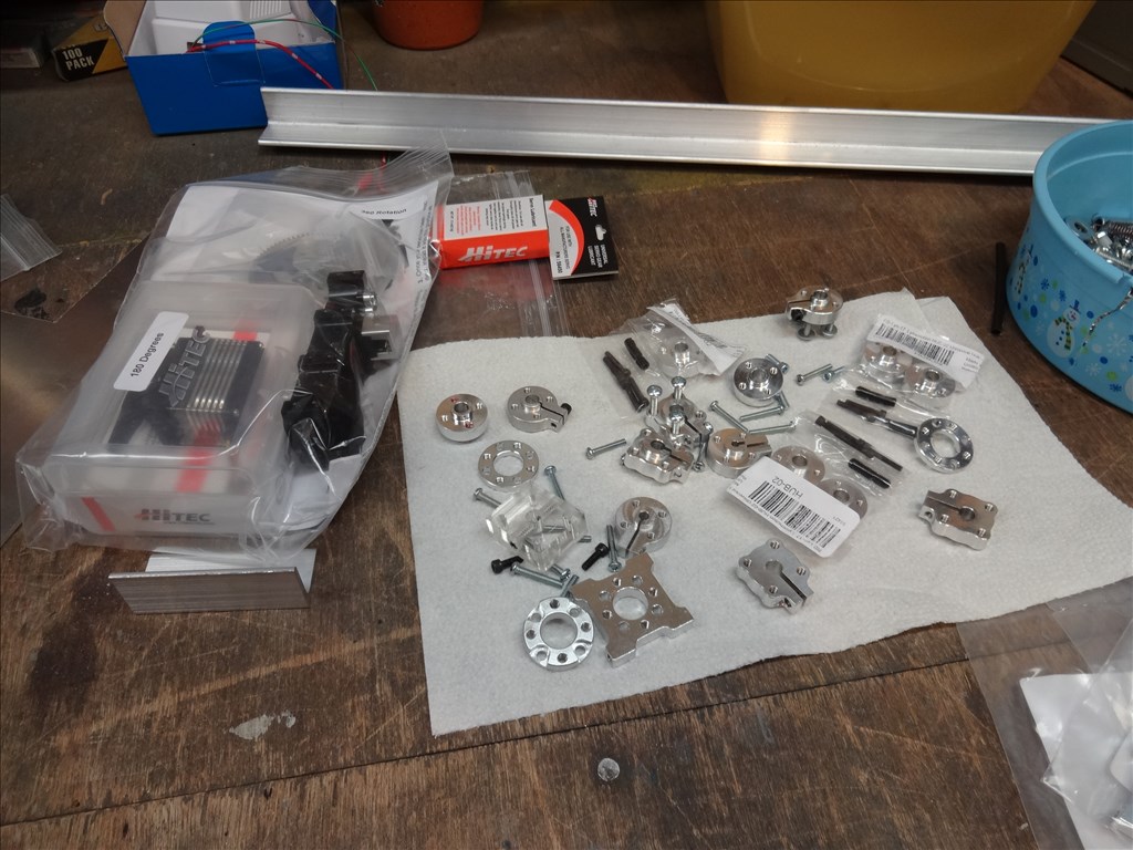
The rail slides for extending the arms (You need to size these to your application. They come in different sizes). DryLin trademark W Mono-Slide System Here's what I ordered: SQUARE DOUBLE Rail: WSQ-10-40 MONO CARRIAGE: WWC-10-40-15
Source for the Molex connectors, pins and pin crimper - You can get these many places like Mouser, Digi Key but I like ordering from a friend of mine who runs a small electronic online store that serves the pinball hobby community. Ed at Great Plains Electronic is the best and very accessible if you have questions. I like to use either 0.062 or 0.093 depending on the application. 0.062 0.093 You'll need a good cripmer for a good connection. They can really cost a lot or a little. You get what you pay for. Here's one that should work OK and not break the bank: Crimper
If you want to learn how to make a good Molex crimp read this section of a web page. It's very well written (actually the whole page is a good read): How to Perform a Good Connector Crimp
Good luck and have fun! Dave
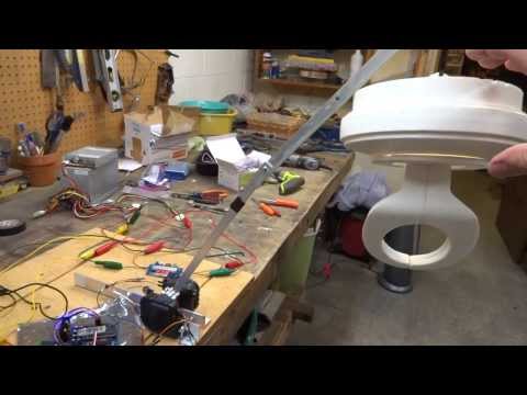
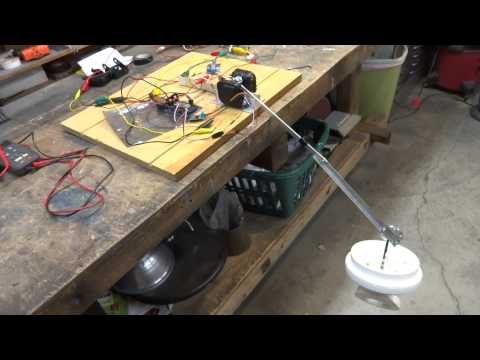
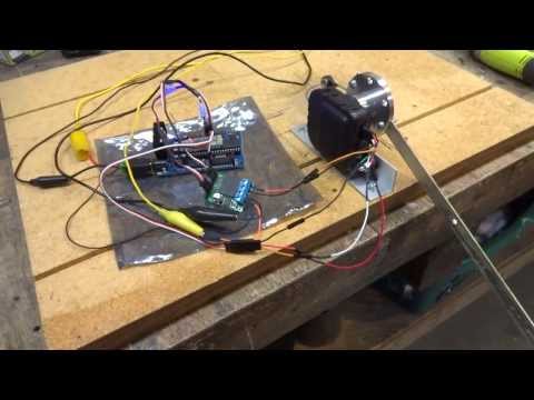
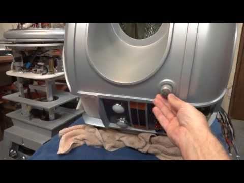
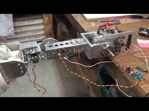
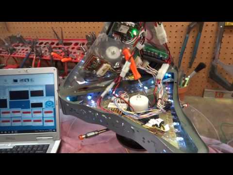
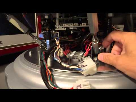
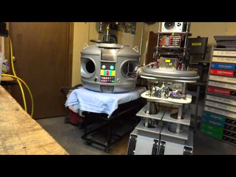
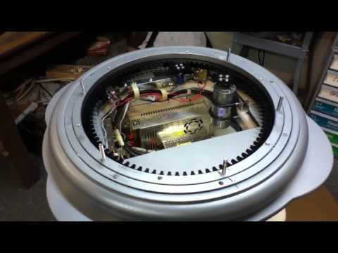
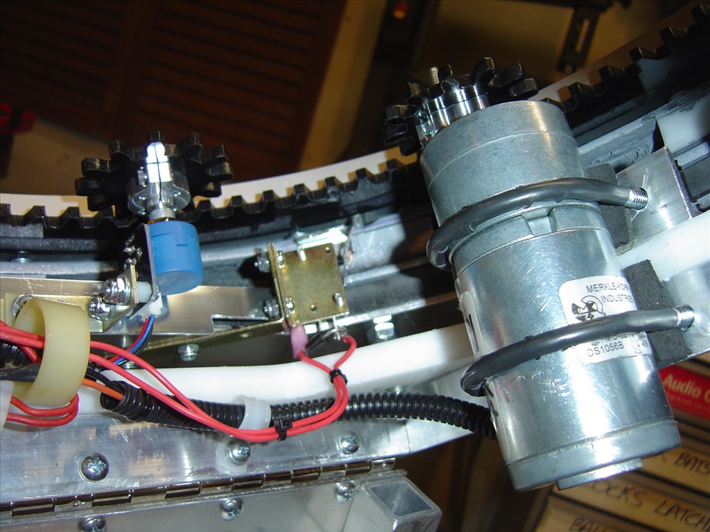
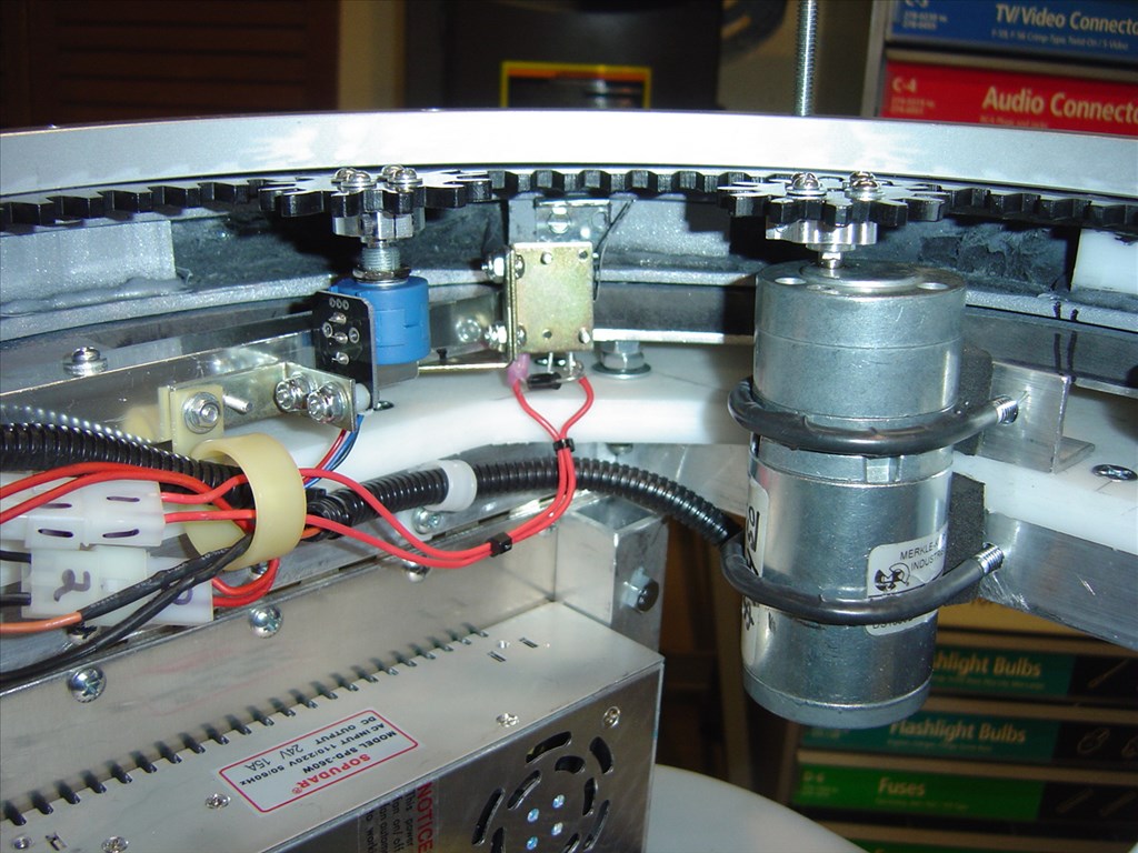
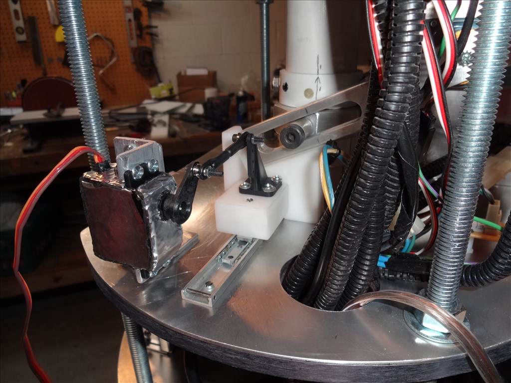
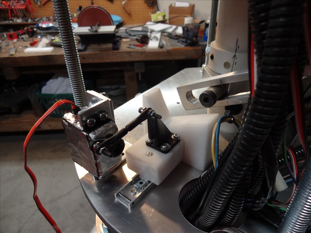
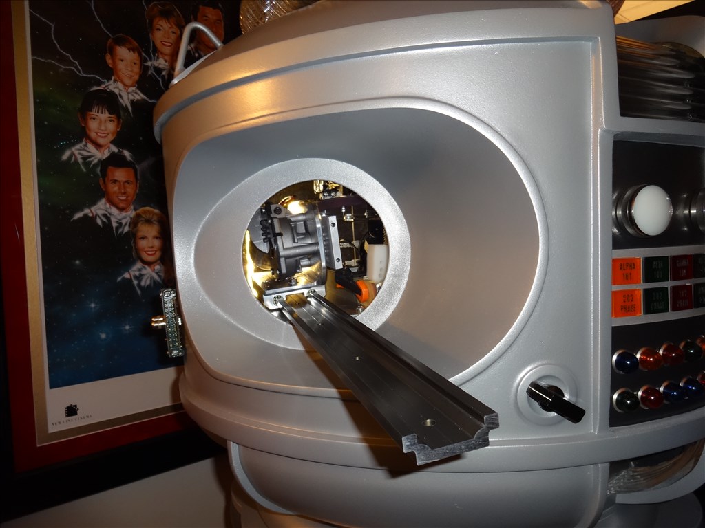
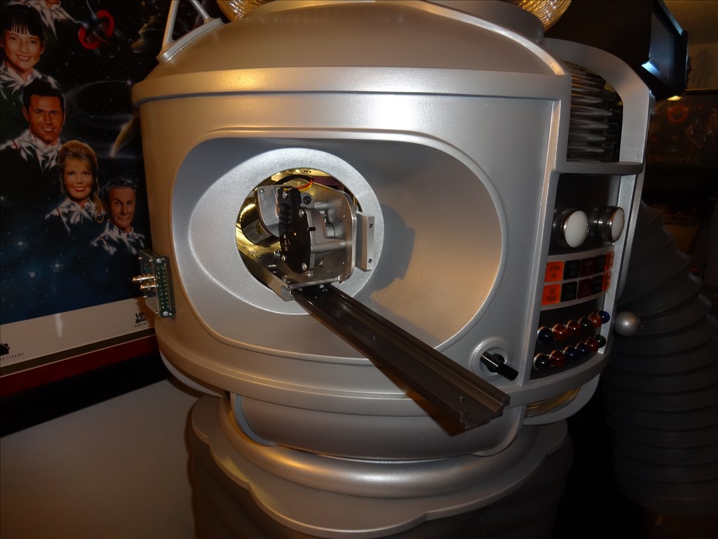
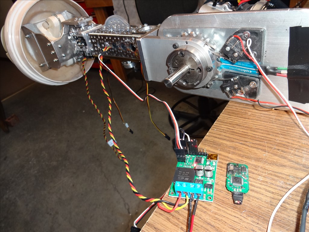
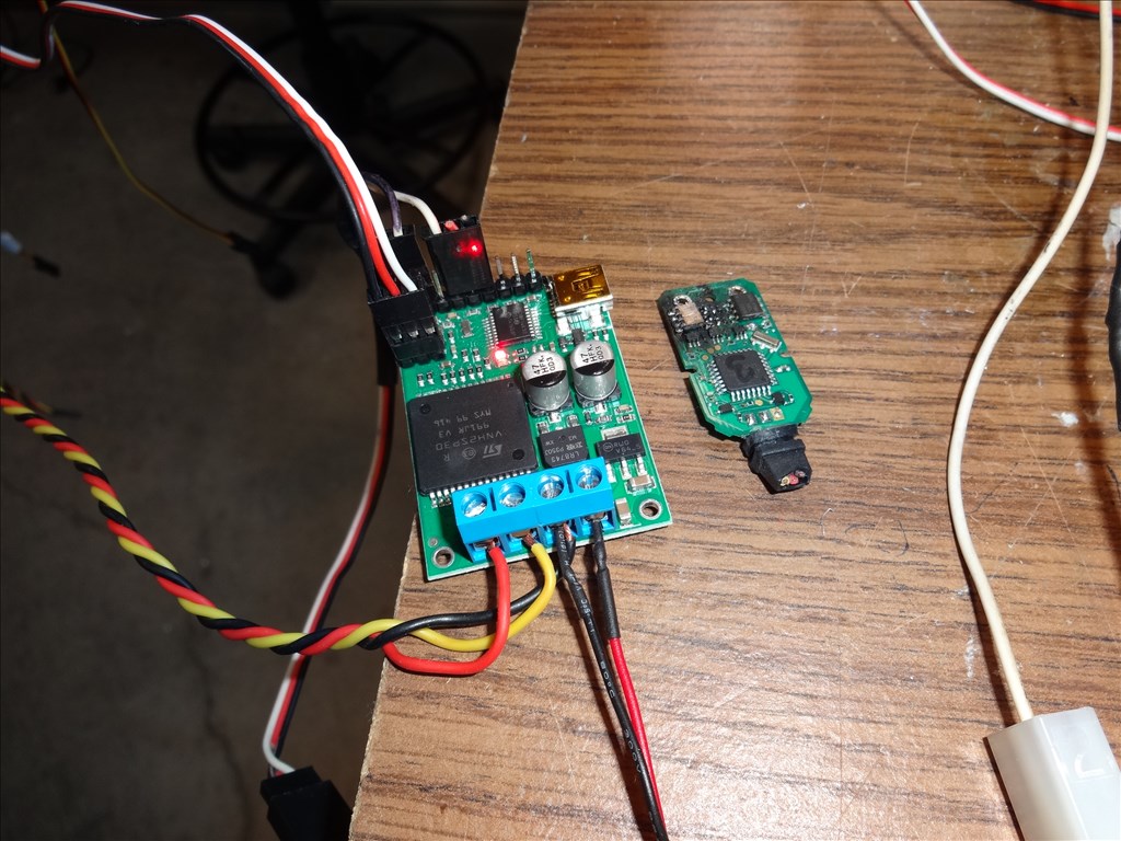
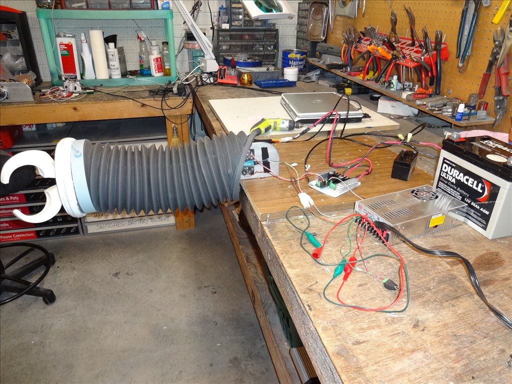
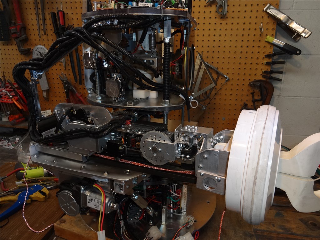
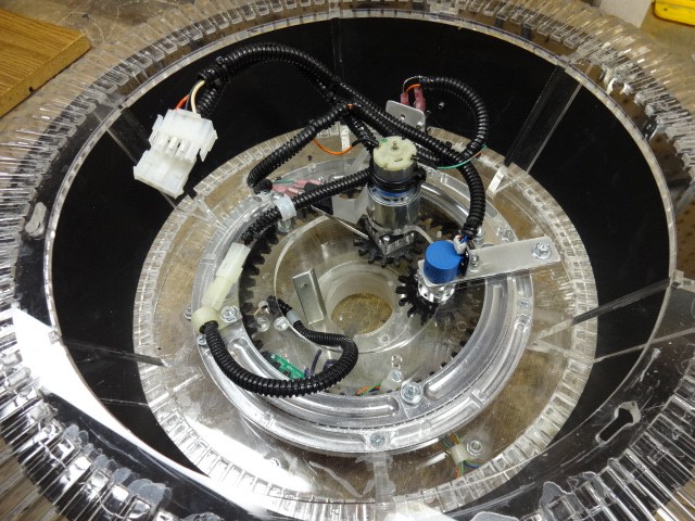
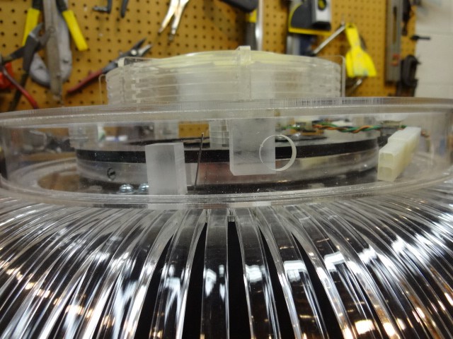
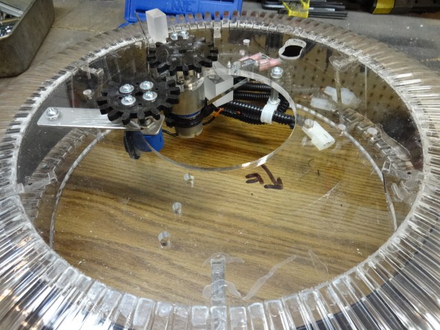
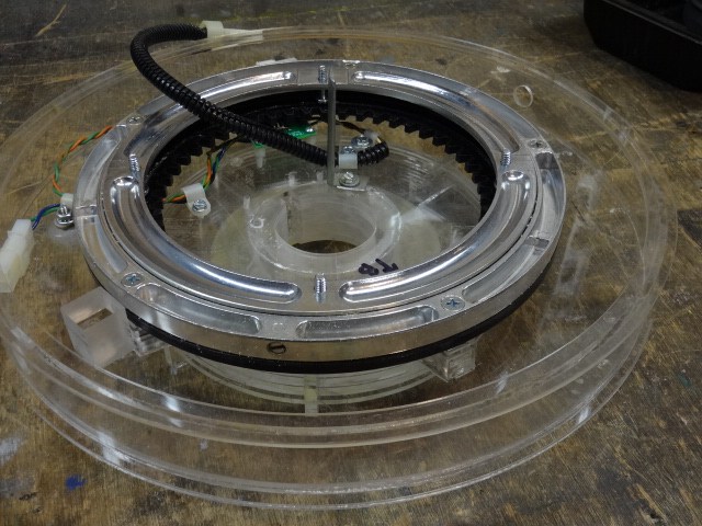
OK, here's part 2 of the last video. This one shows the rail and mounting system with the torso off. I explain how to dissemble the unit through the 7" arm hole and from the torso vents below as I explained in my last post. I also show the electric car window motor I'm going to use to move the arm in and out of the torso. I hook it up to a 12v source and try to stall it while taking amp readings. Spoiler Alert: I cant do it and the amps go from a no load reading of 2.5 amps to a full load amp reading of about 11 amps or so. Enjoy: