18 Inch Tall R2d2

rsmith

USA
robot video thumbnail

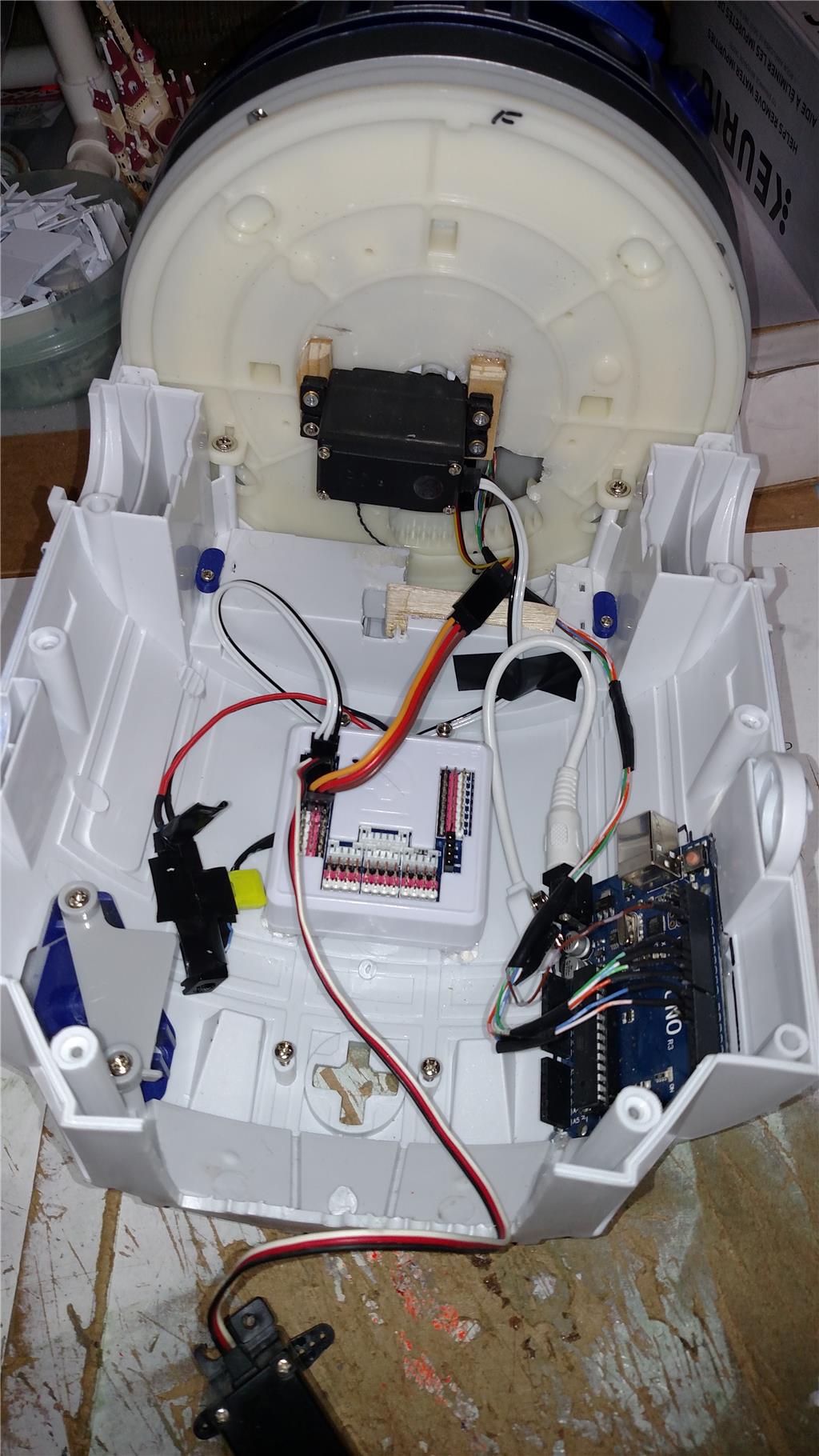
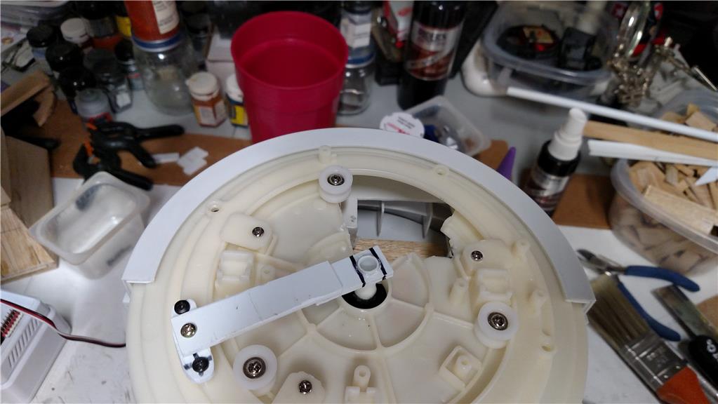
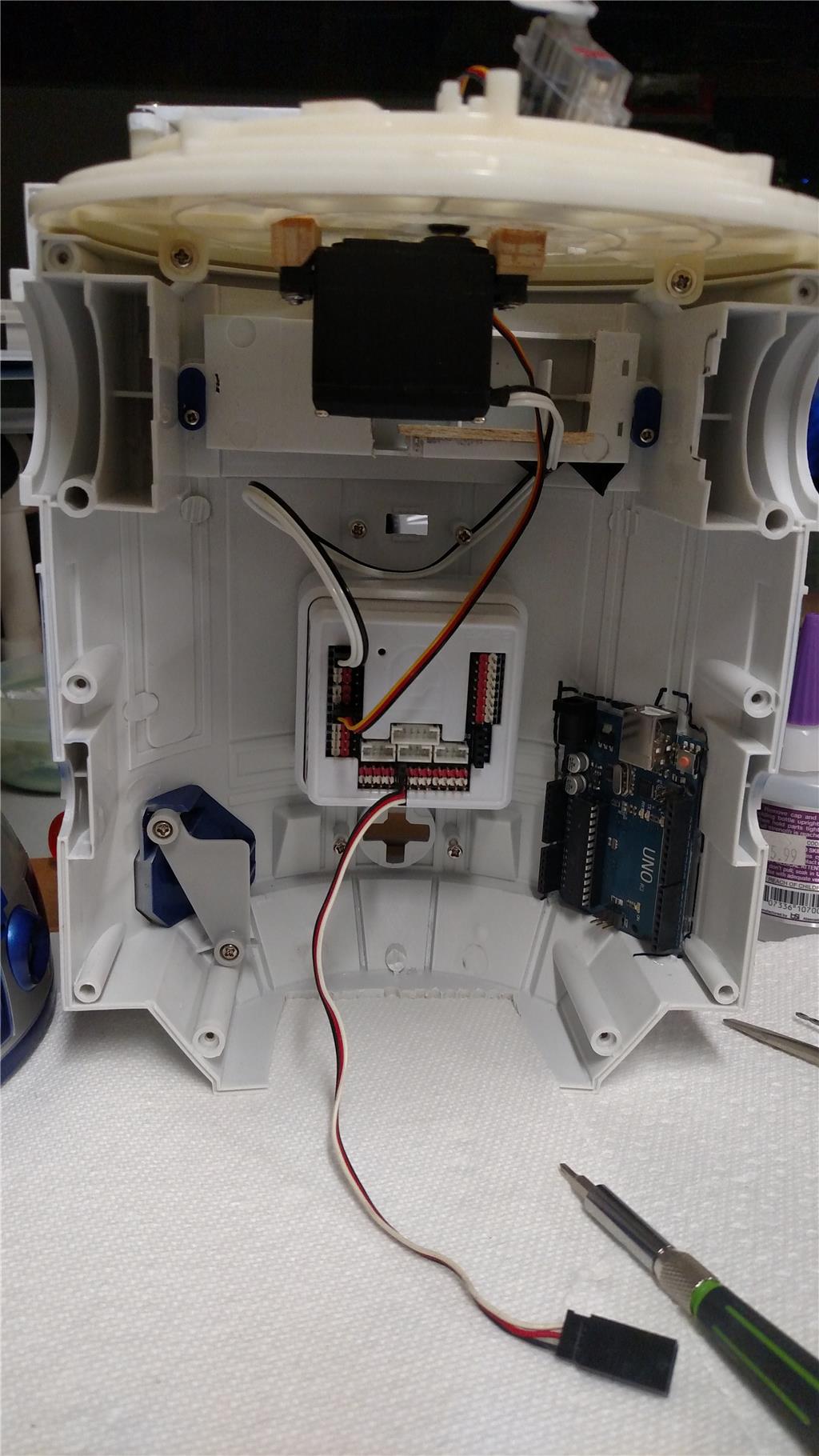
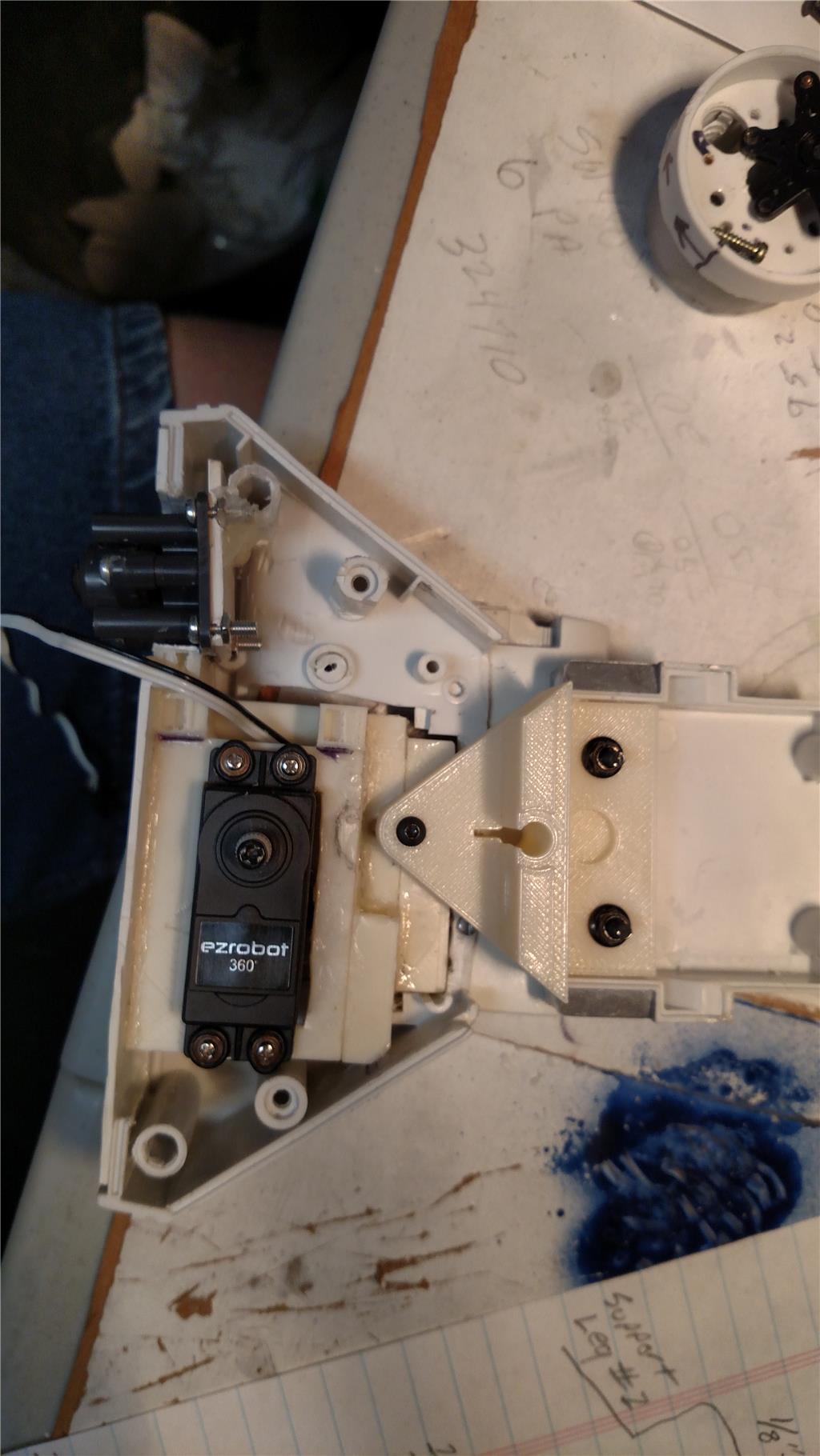
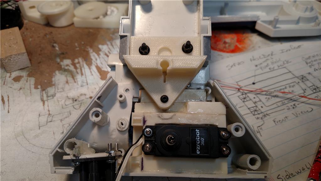
I am currently working on an 18 inch tall R2D2 that was purchased from Toys-R-US. This R2D2 had no electronics in it at all, just a pose able plastic model. It has a simple lazy susan type setup for the head movement. It has an upper gear and a lower plate. I put a EZ-Robot 360 degree (continuous) rotation servo in for the gear to rotate the head. The problem that I am having now is that the continuous rotation servo is difficult to stop at a give point, say 90 degrees. This faces my R2D2 head to the front. How would I control it like an Auto Position control, yet get the 360 degrees of movement out of it. with the Auto Position control I only get 180 degrees of movement. I am on a tight budget (unemployed) and am using what I have at my house for most everything I want to do with this R2 unit. The issue that I am having with the Auto Position is that once it hits the point it should stop, the servo keeps going until I hit the panic button to stop it. The stop button has no effect. Any idea's would be helpful. I have been programming with the EZ-Robot for about 4 months, but have programmed for 6 years with legacy software.

Regards, Richard

By — Last update

ARC Pro

Upgrade to ARC Pro

Take control of your robot's destiny by subscribing to Synthiam ARC Pro, and watch it evolve into a versatile and responsive machine.

PRO
USA
#1  

Richard,

Some useful links:

A continuous servo does not have position, more info here: https://synthiam.com/Support?id=11

similar problem: https://synthiam.com/Community/Questions/10698

similar build: https://synthiam.com/Community/Questions/8670

#2  

Hello @rsmith

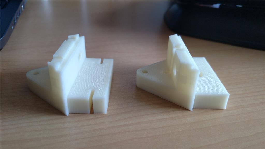
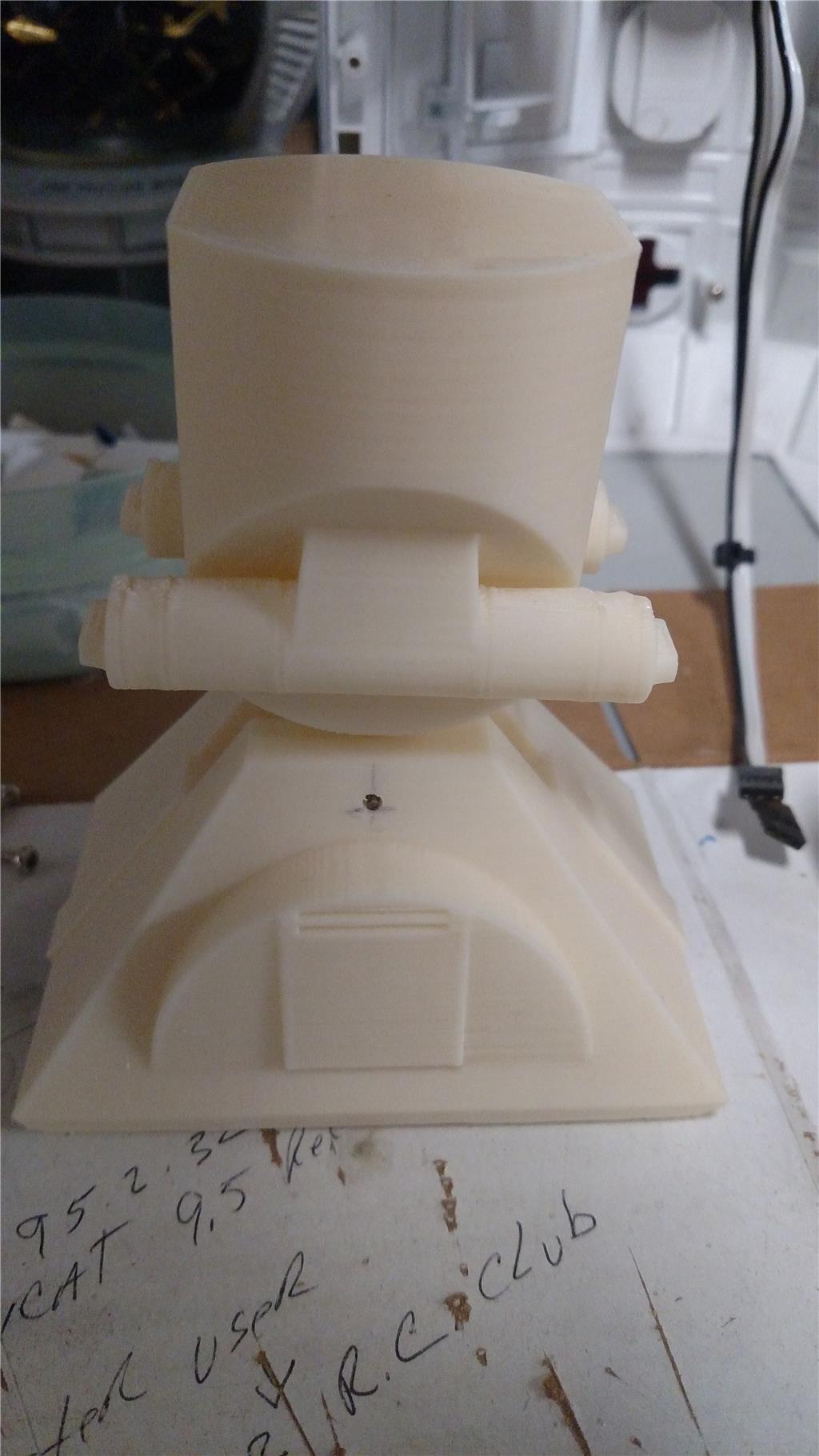
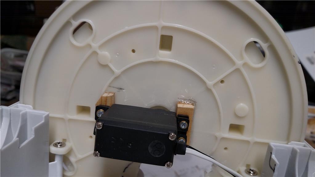
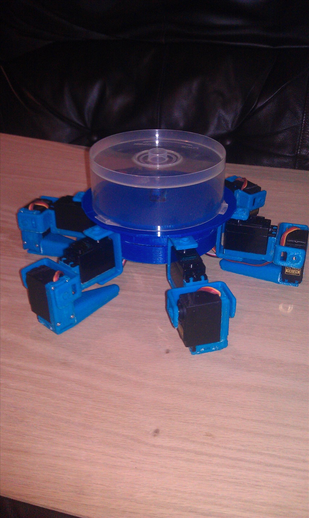
I built the same one you purchased. I did a Showcase which has the conversion build. I used simple parts I 3d printed, but you can make the parts if a printer is not available. Check out the link below.

https://synthiam.com/Community/Questions/8670

Ron

@ptp A quick Hello !

#3  

I forgot to mention, I originally used a continuous servo as you described, (.stl file included for a 3d print) but changed it to a direct drive using a standard servo. The speed and action is much better even though you don't get 360 degree movement.

#4  

Thank you to @PTP and @AndyRoid for the review of a continuous rotation servo. I had missed the part about positioning of it. I am looking at Andy's showcase at this writing. It has been a great read so far. Looking at the similar issue link posted by @PTP, it seems that a winch servo was used for the periscope and will be for the dome rotation on that project. I will also be checking out the winch servo. As I intend on putting a periscope and radar dish in my R2.

Thank you again for the assistance. If there is anything else that comes to mind, for this project please keep the idea's coming.

Regards, Richard

#5  

Don't forget to post a picture of your progress.

#6  

Winch servos are a good idea, however out of the budget for the time being.

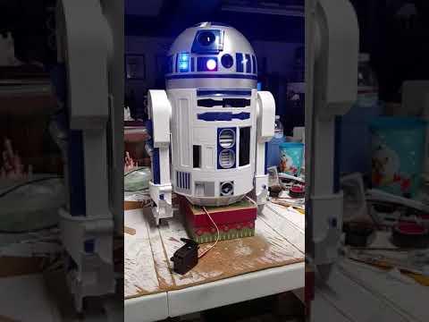
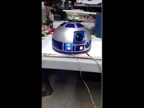
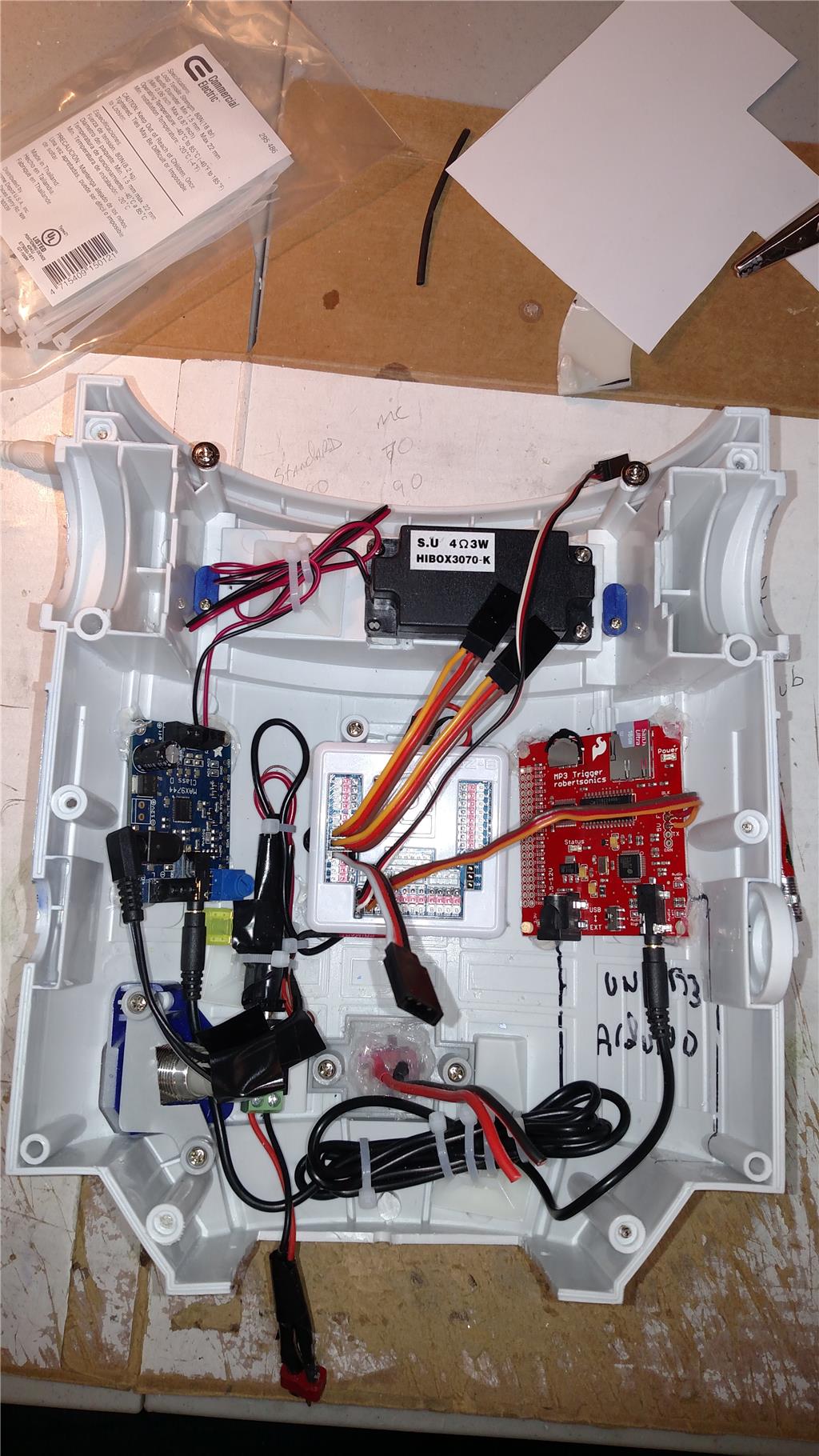
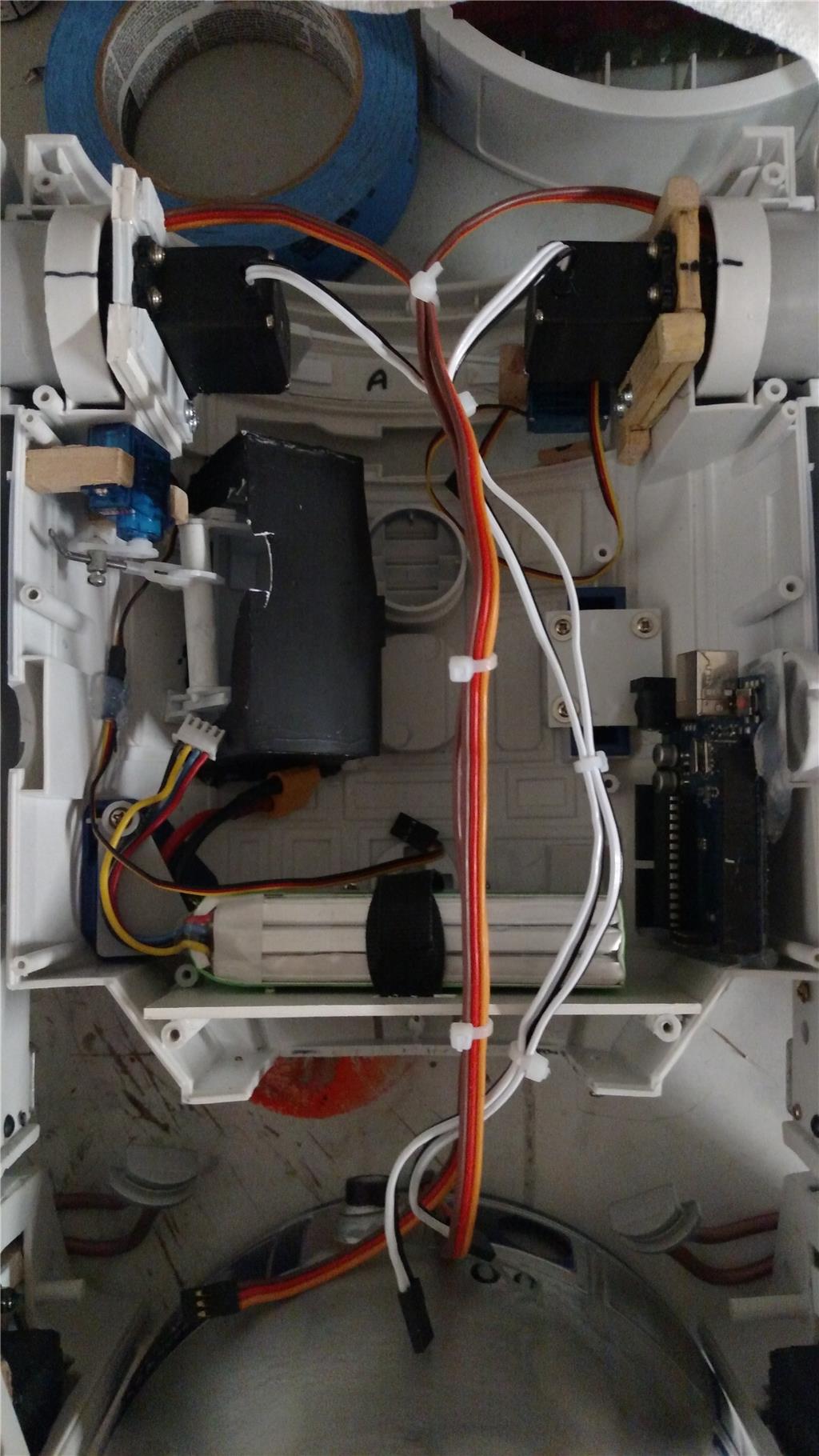
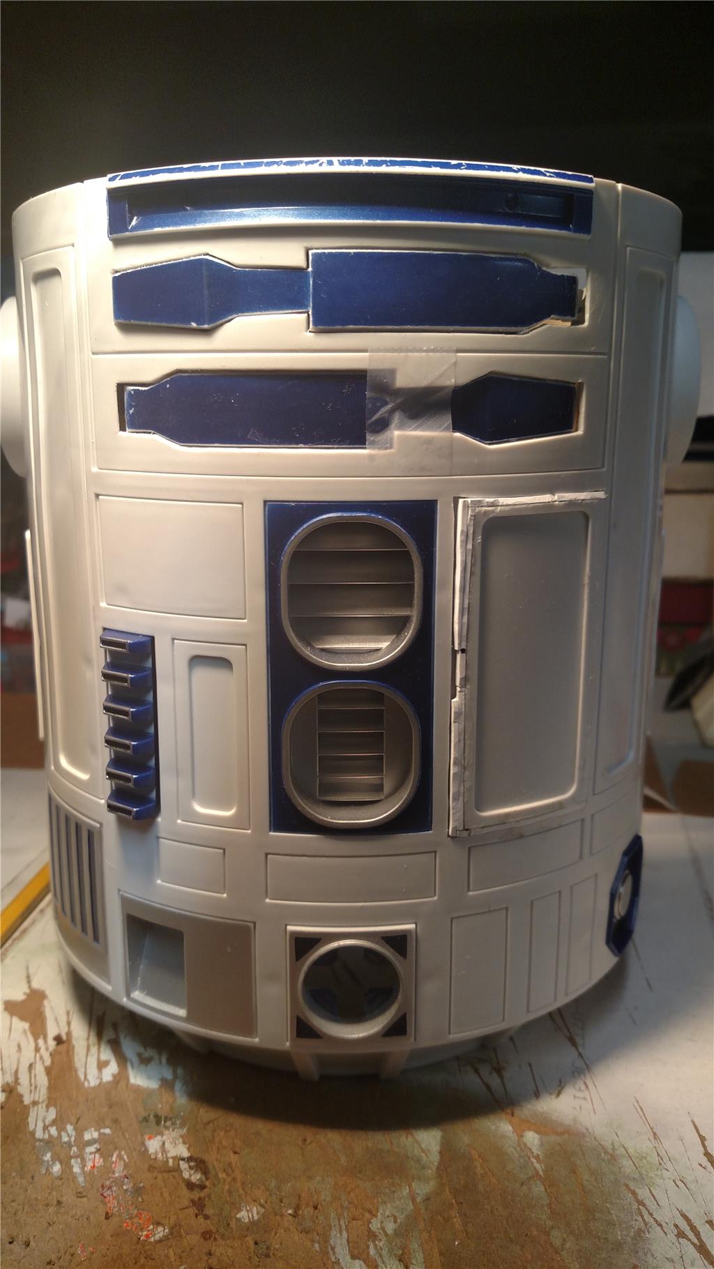
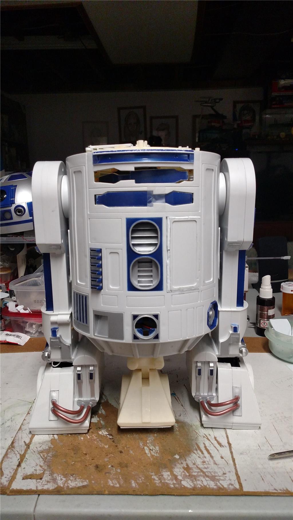
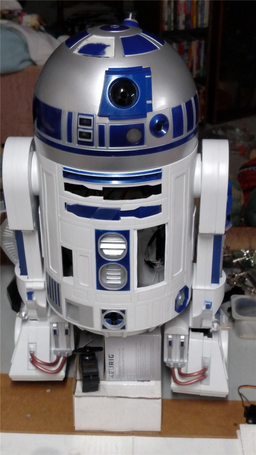
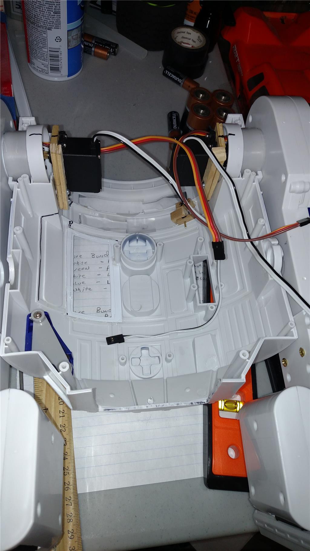
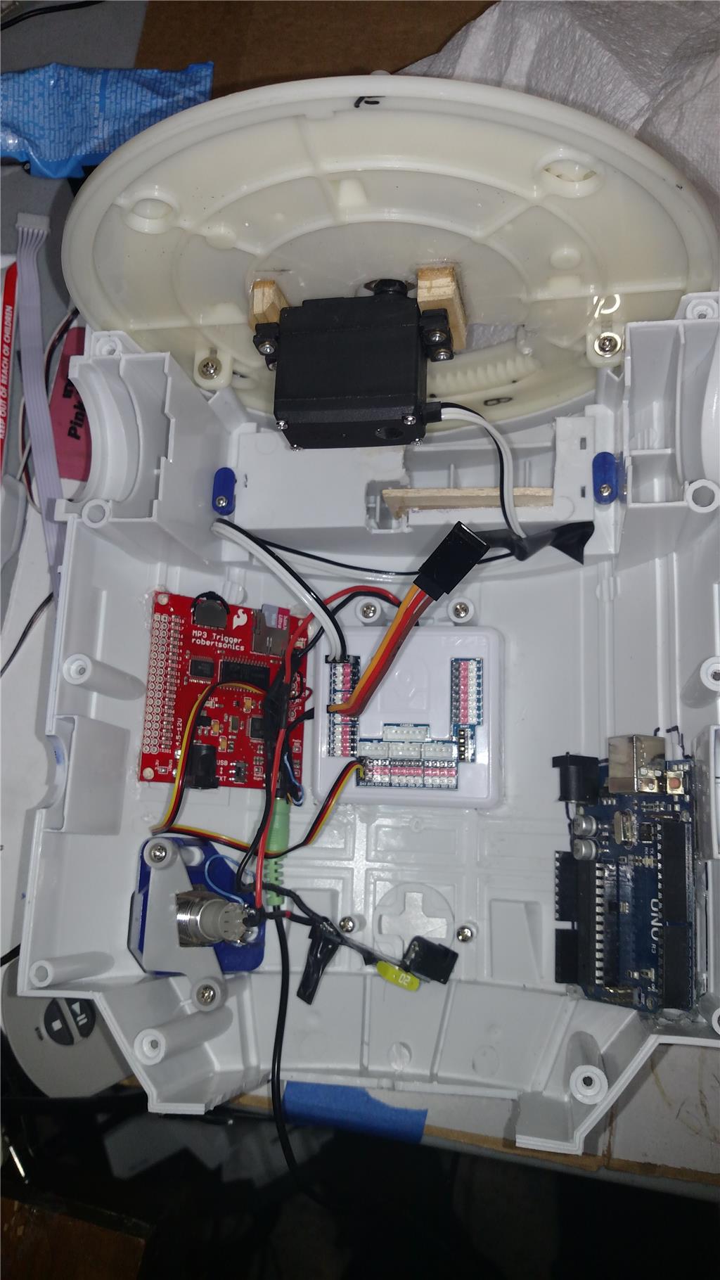
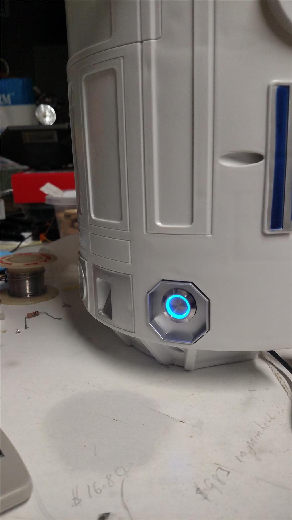
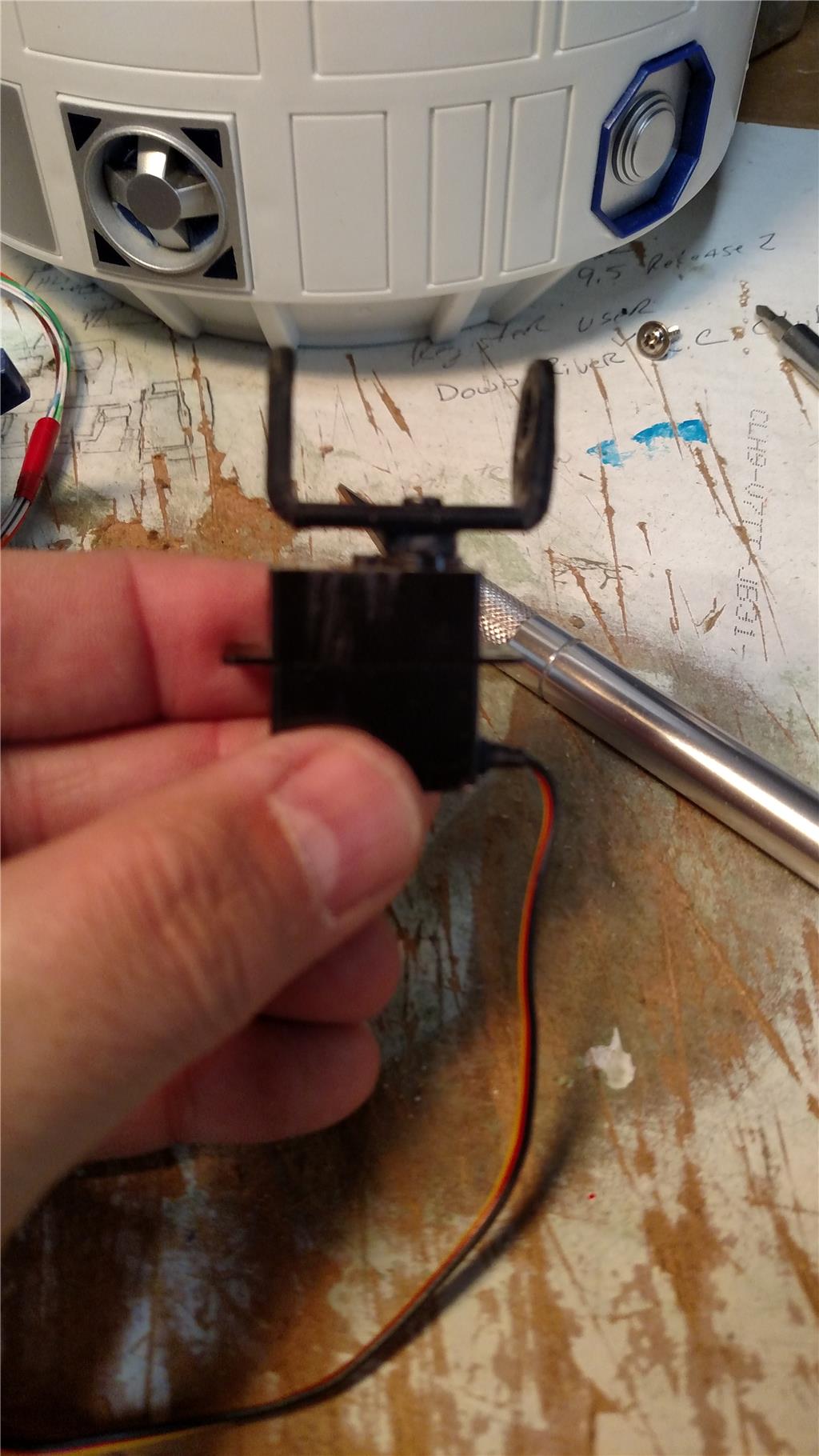
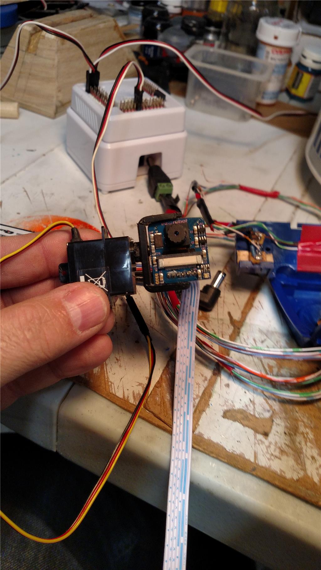
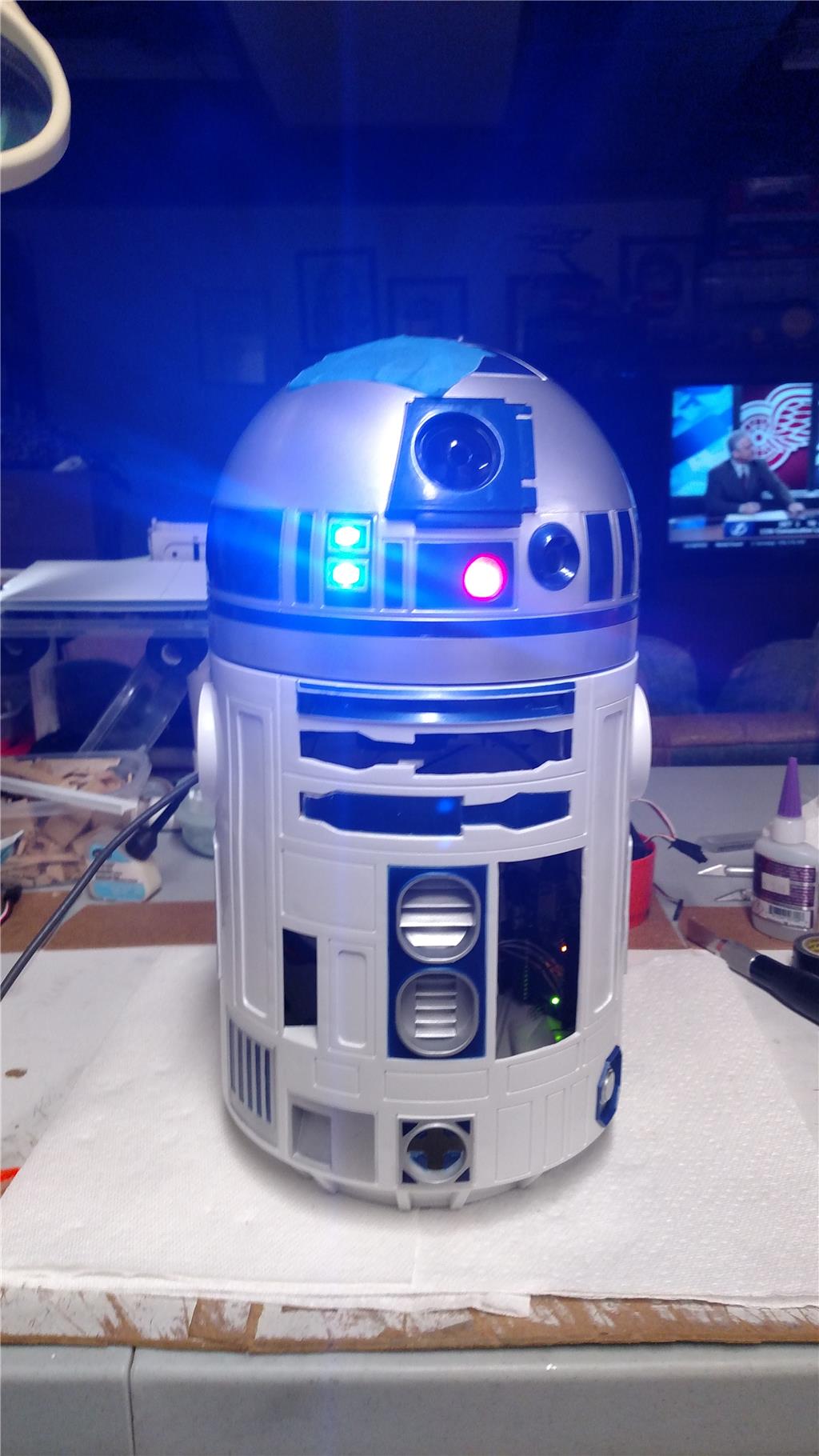
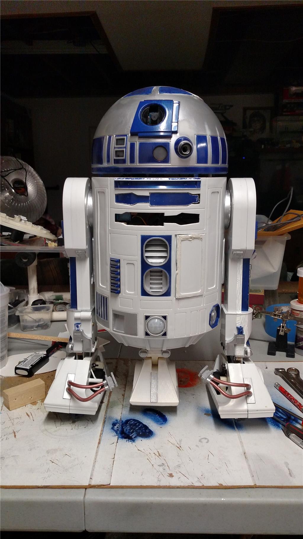
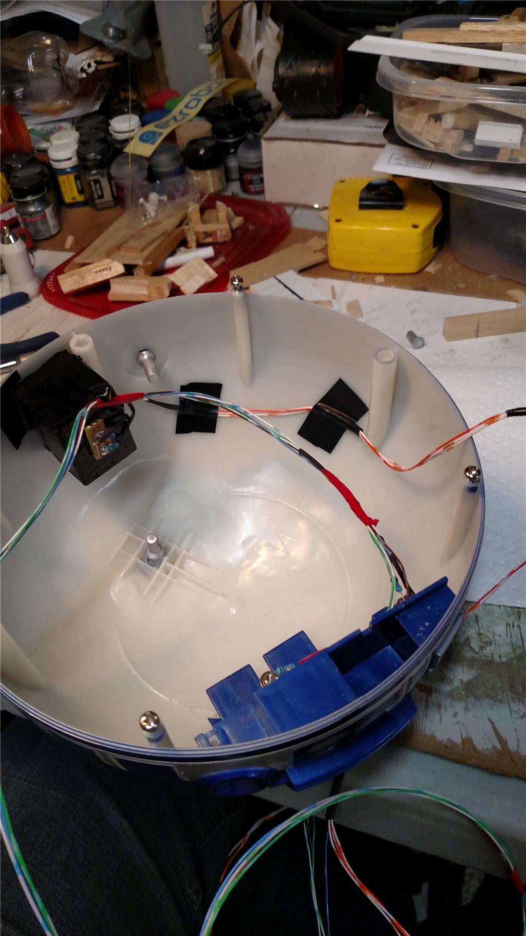
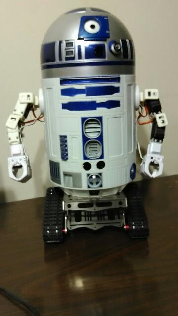
@AndyRoid Here is a Youtube video and some pics from my R2D2 project so far. I have stopped working on R2 Dome rotation for the time being. I would like to get a few more items completed in the mean time. I am going for broke and adding as much as I can. I have been working on my Lost in Space 1/6 scale B9 Robot model. Most of the issue with the B9 is space. Dave Schilpous has helped me along with the B9. Anyway back to R2. I did the really easy part of putting LEDs in the dome first. For testing they are run by and Arduino Mega, running my Custom Mustang Knight Rider Sketch. I am also putting the EZ-robot camera from the Developers kit, in R2 front holo projector socket. It fits really good but the green LED for the camera is bright and shines right through R2 dome. Not good. A little bit of black paint on the inside of R2 Dome and it should be gone.

User-inserted image

User-inserted image

User-inserted image

#7  

Thanks for the update... Looking good.

#8  

Thank you for the positive feedback, Andy.

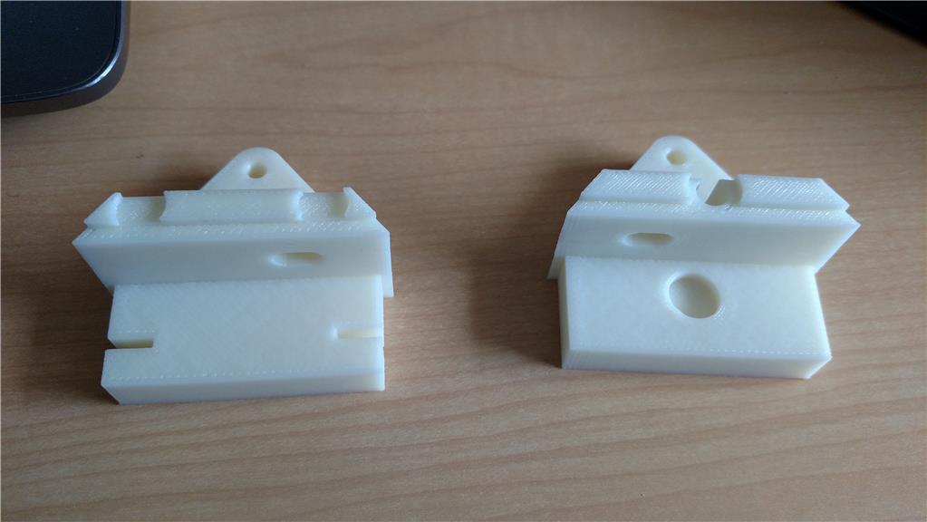
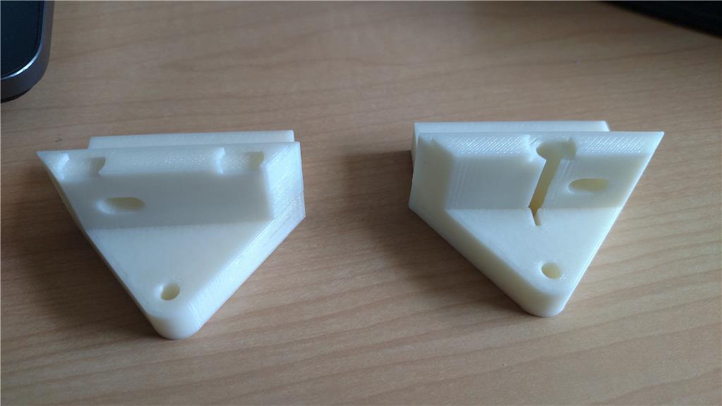
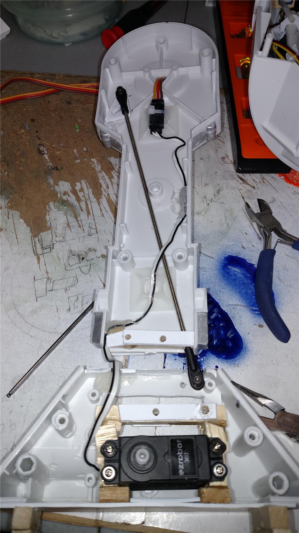
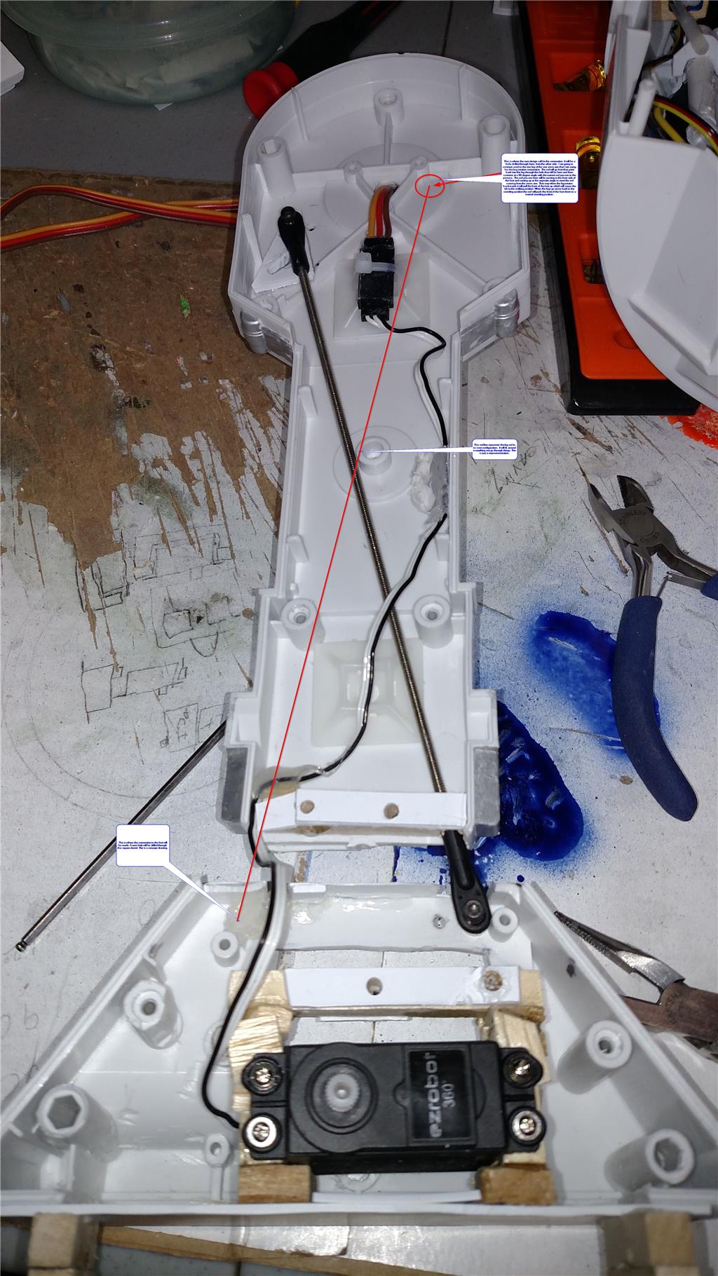
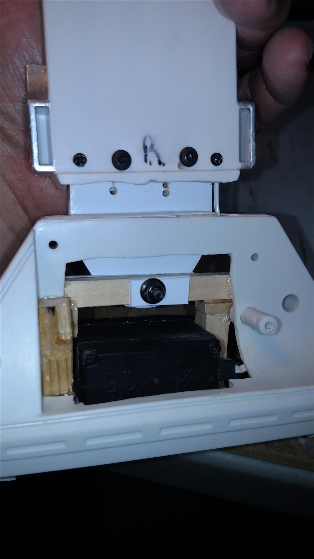
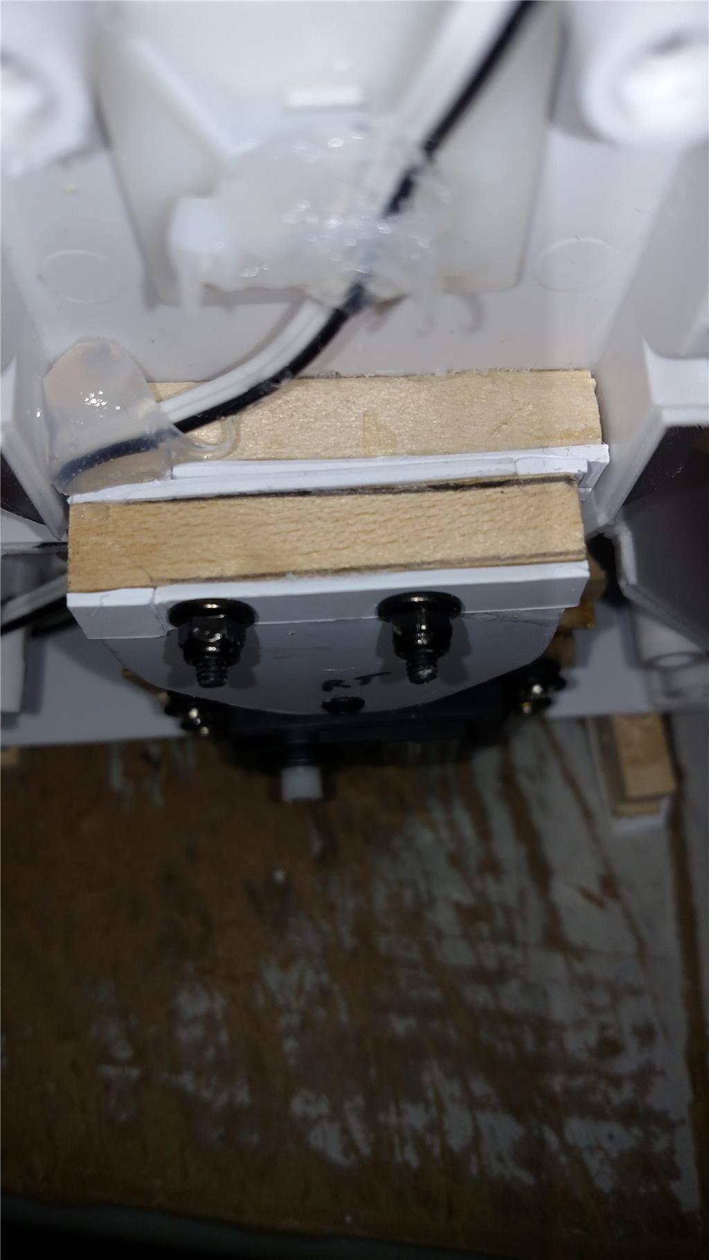
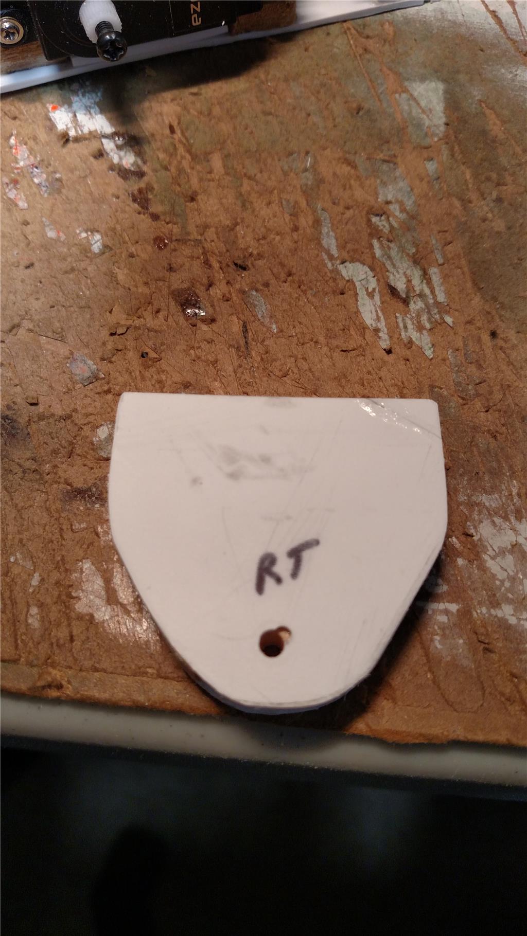
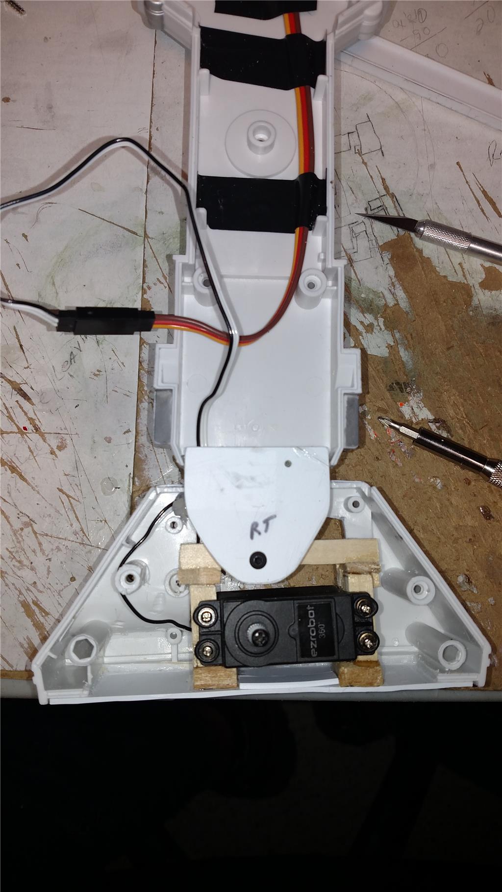
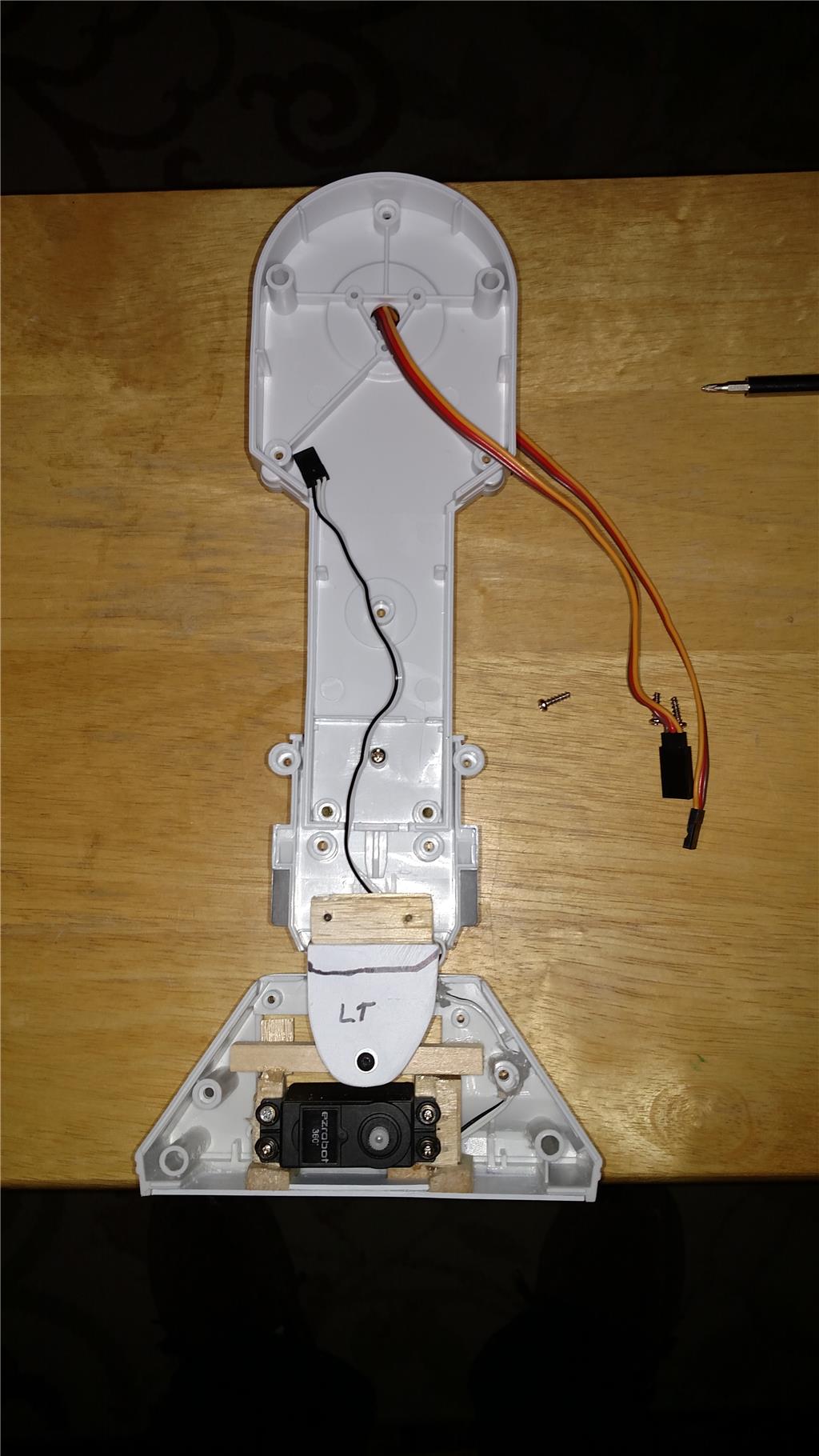
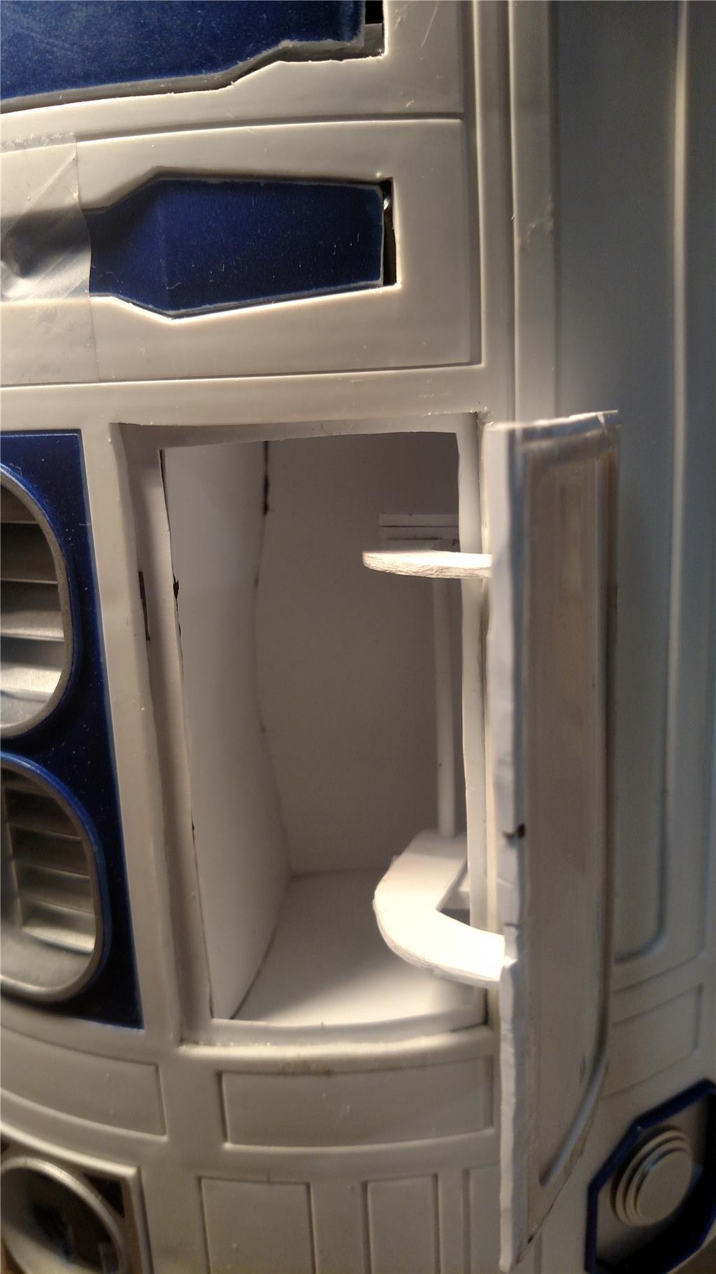
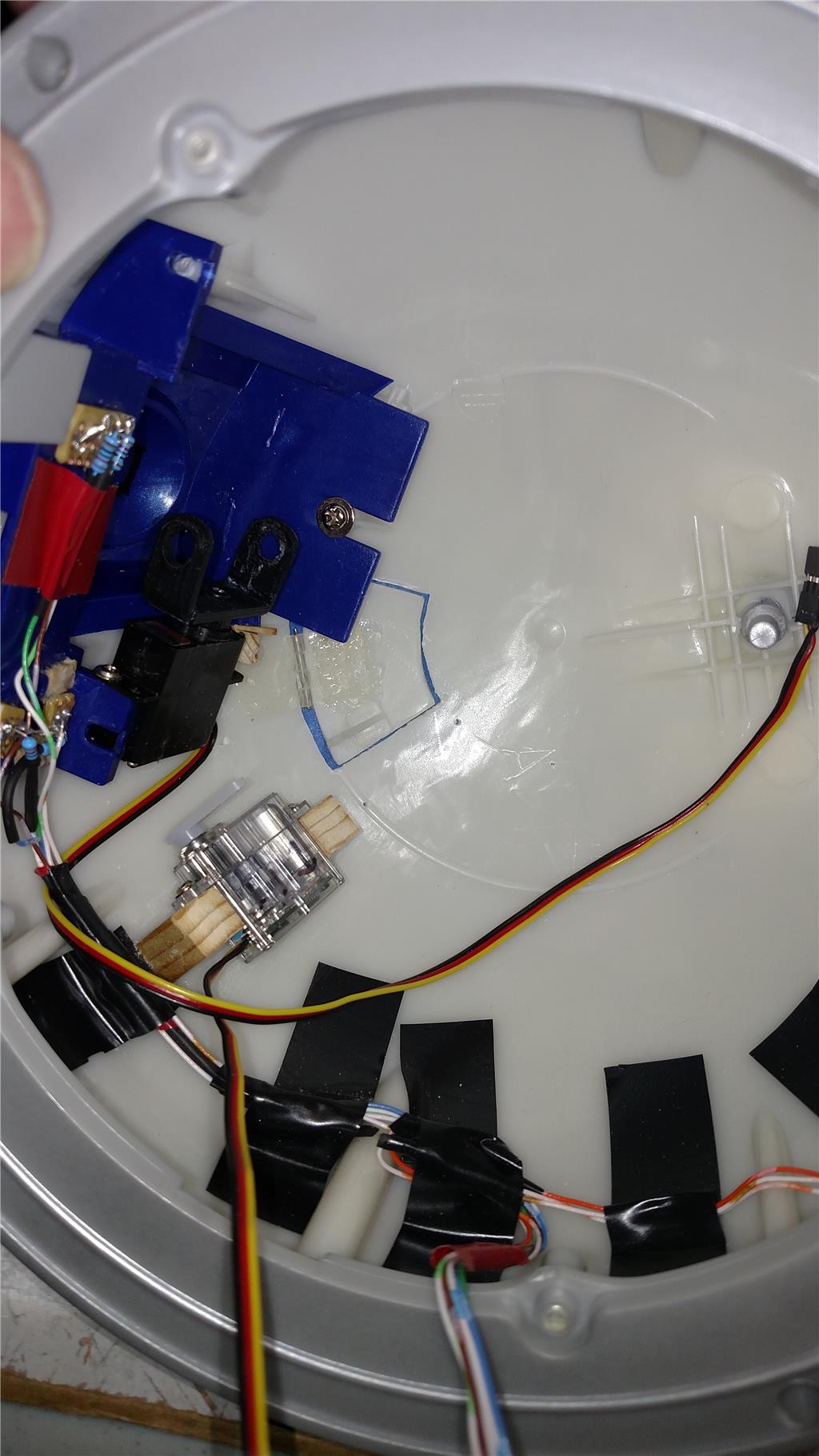
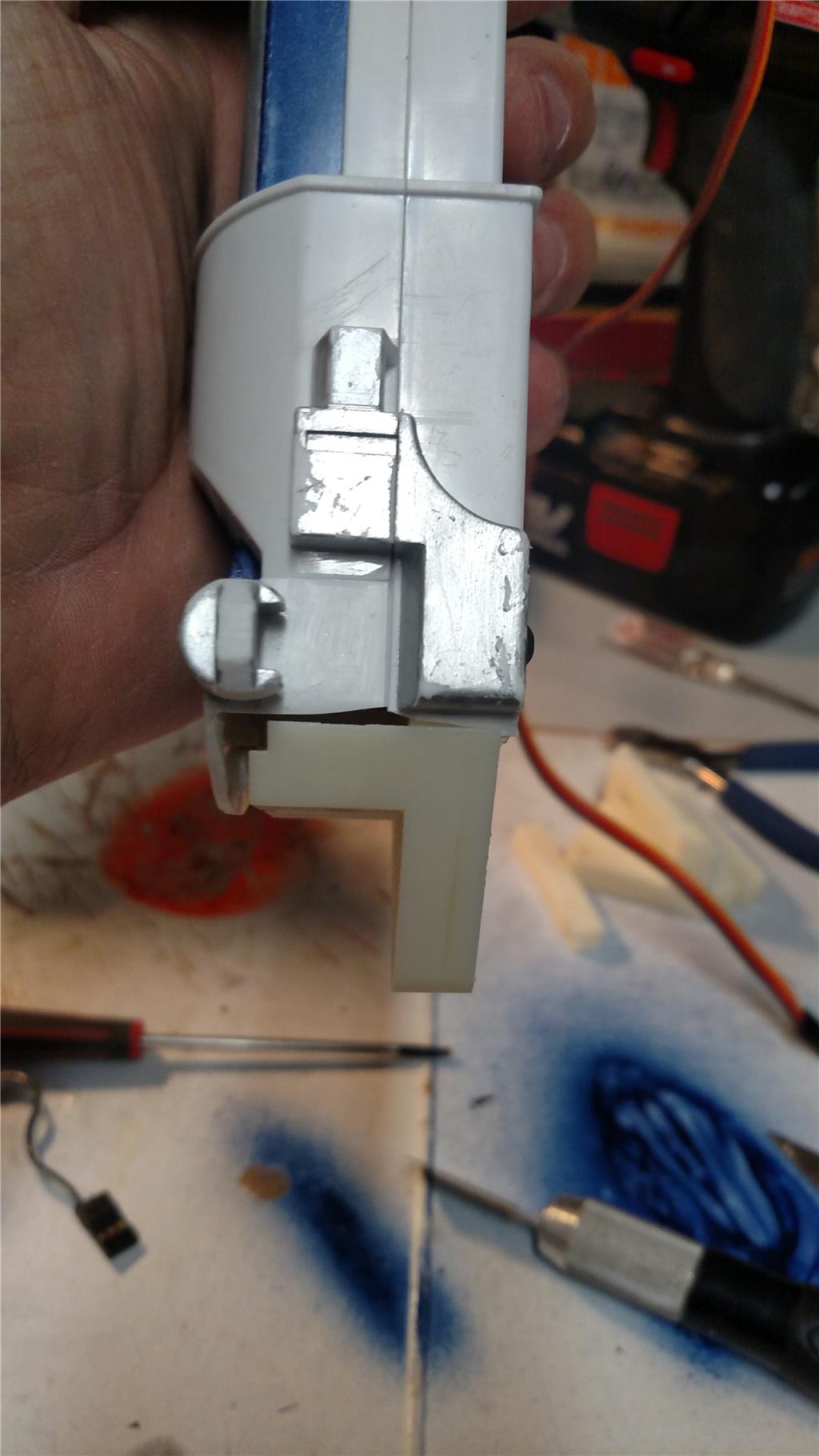
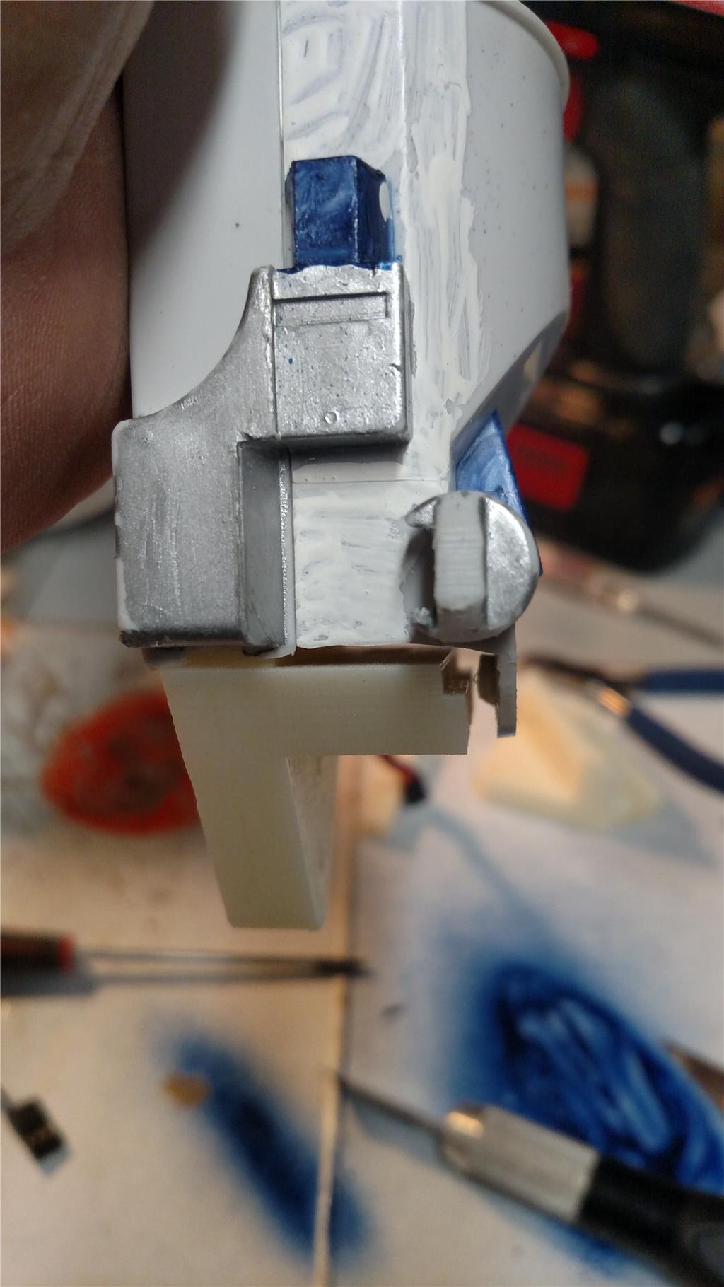
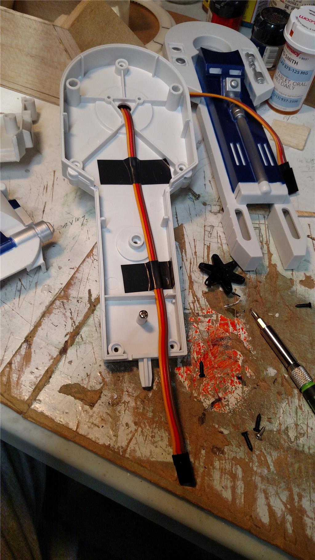
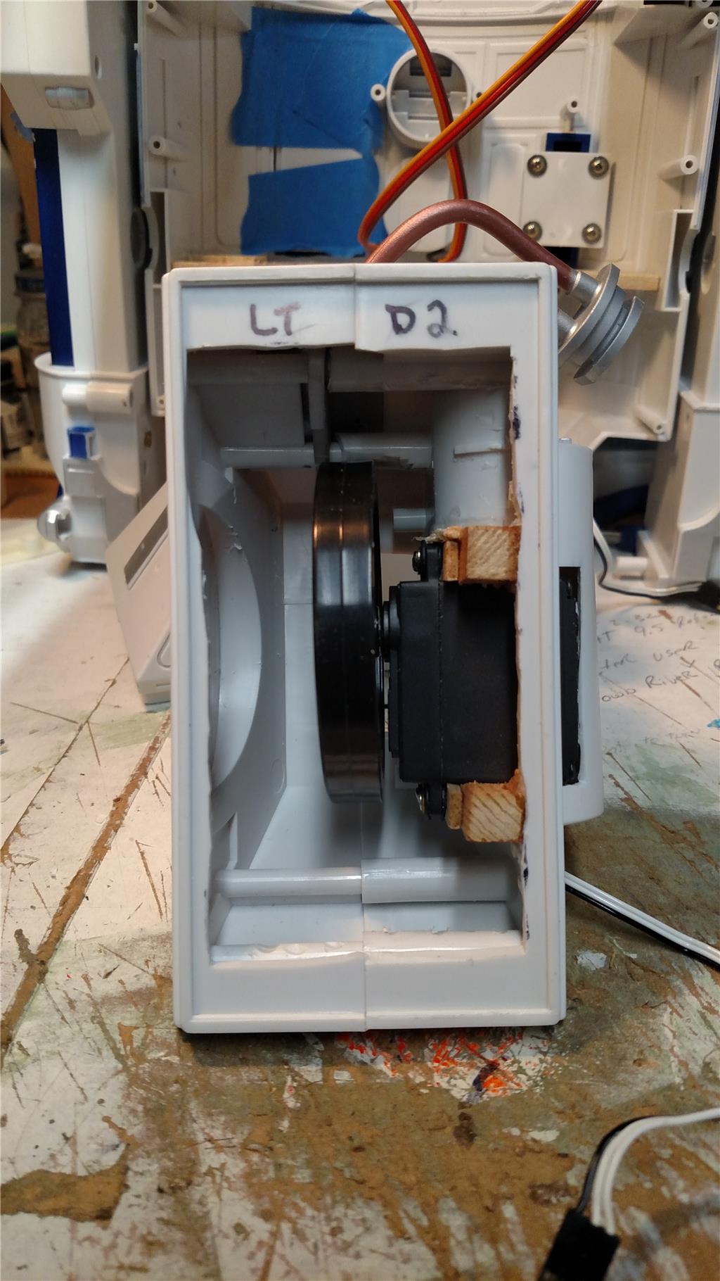
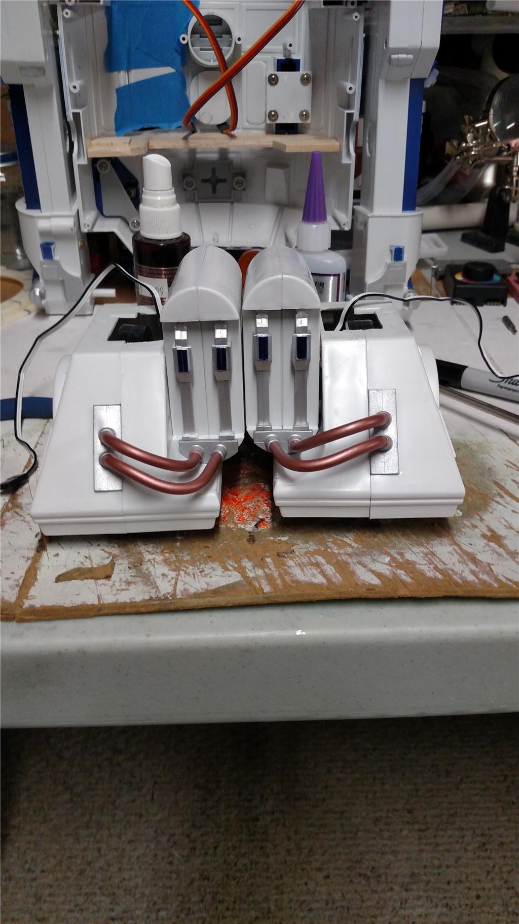
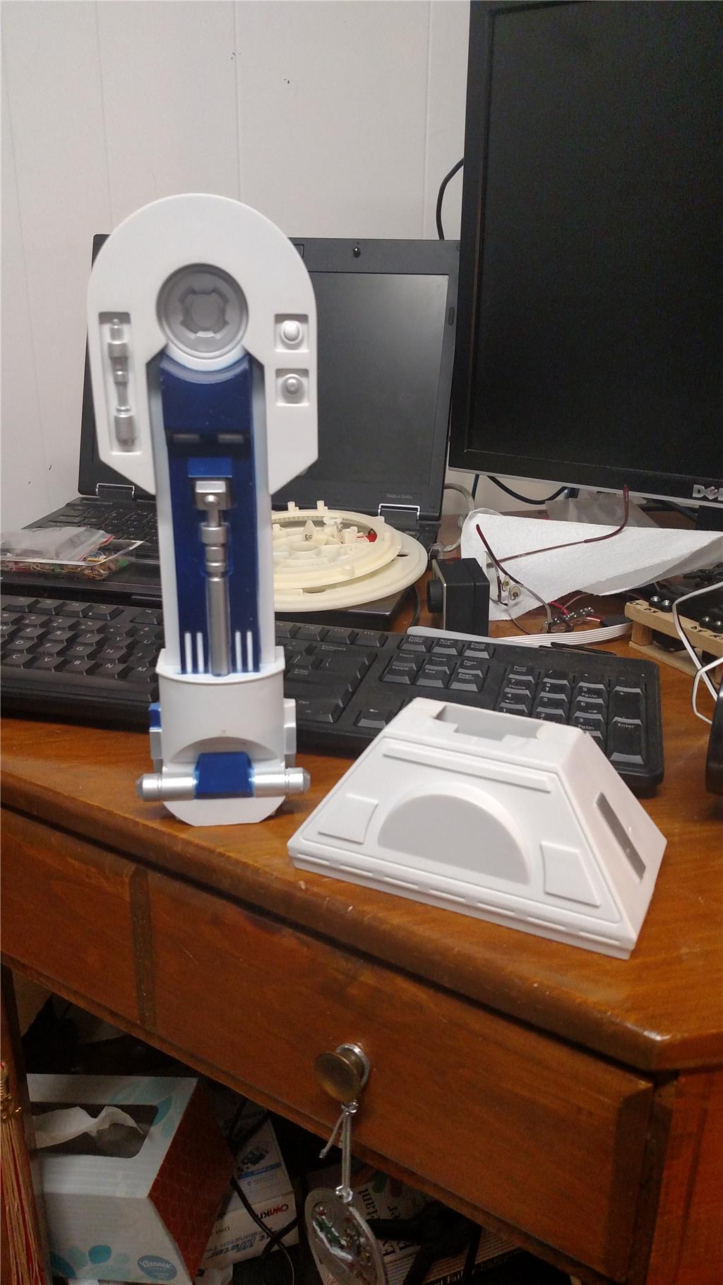
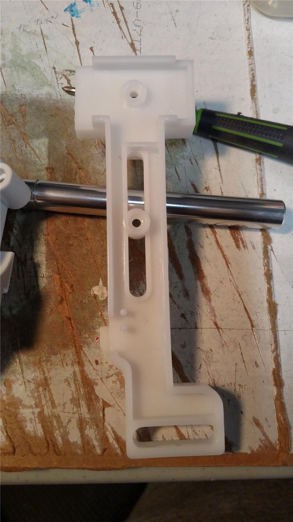
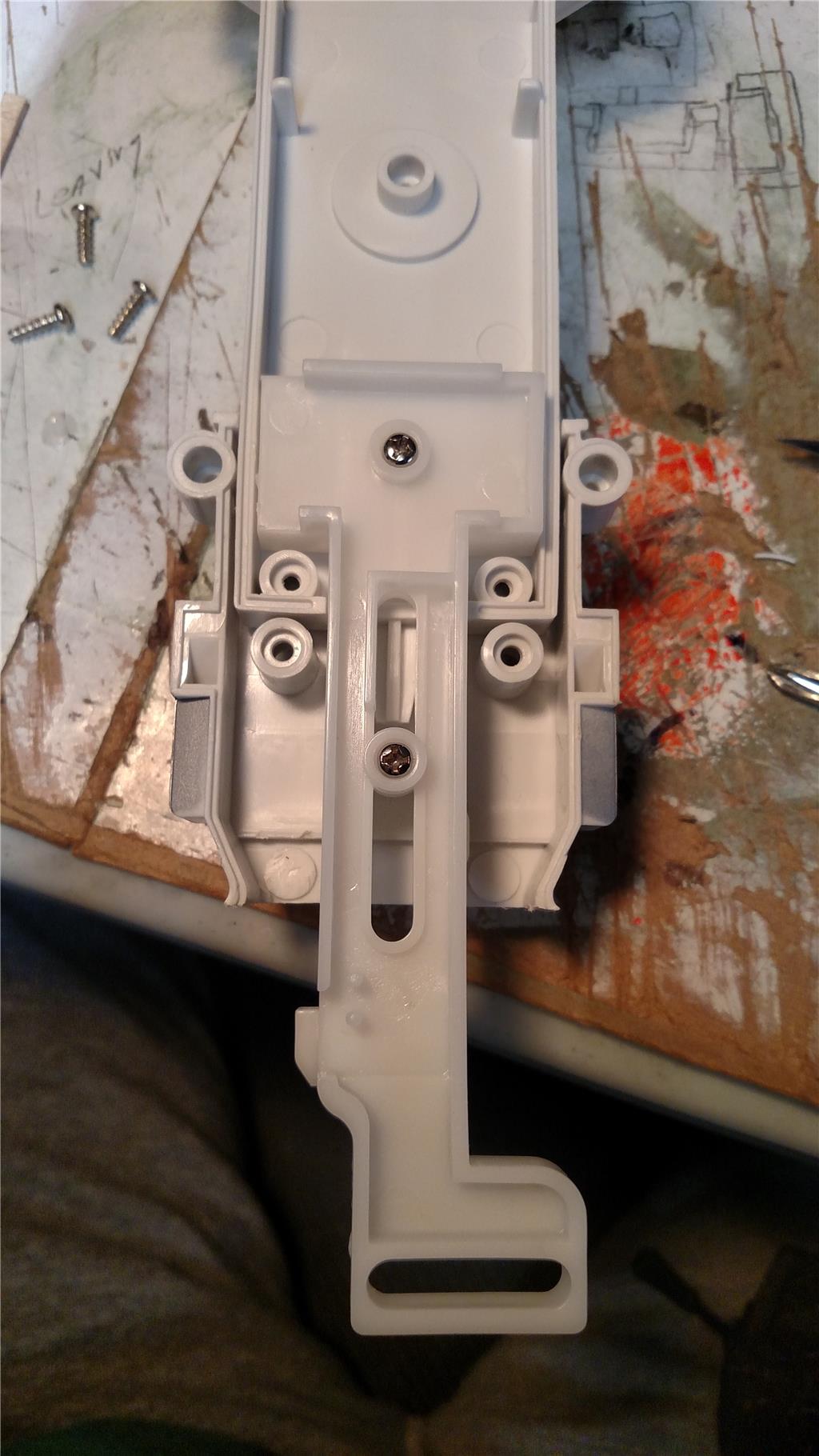
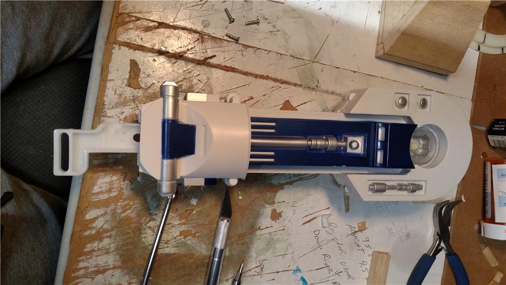
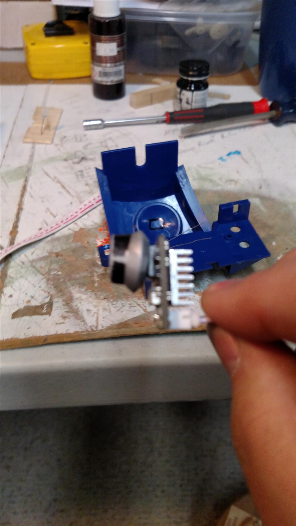
I figured out what the milky white colored piece is for within R2 one leg. When R2 is standing on his 2 legs and the center ankle/foot is retracted, he "bounces" around in what appears to be a "happy" kinda dance. That plunger (as someone called it) is for the "bounce" action. It will push/pull the ankle/foot up and down, therefore looking like R2 is "bouncing" and being "Happy". I have added a couple of photos with this post showing the plunger fixed in place as I believe it was when purchased. I am removing the "plunger" for the time being.

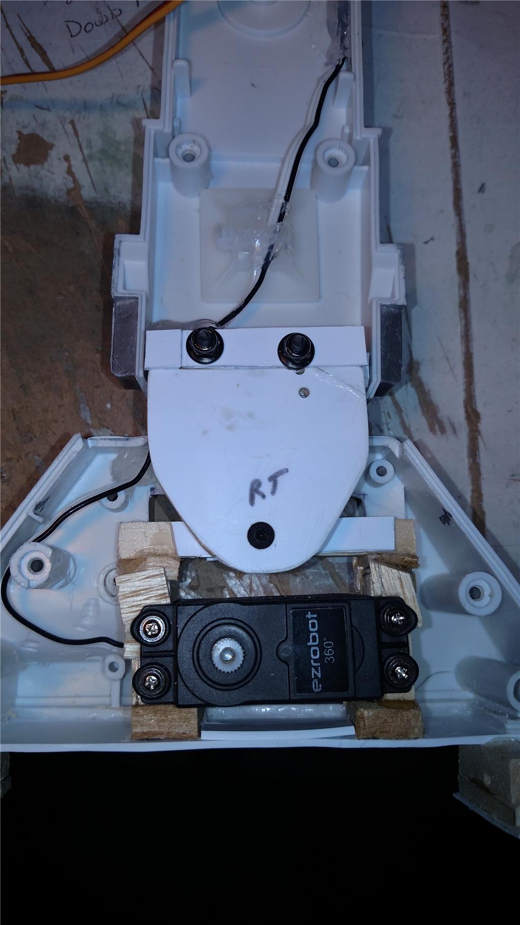
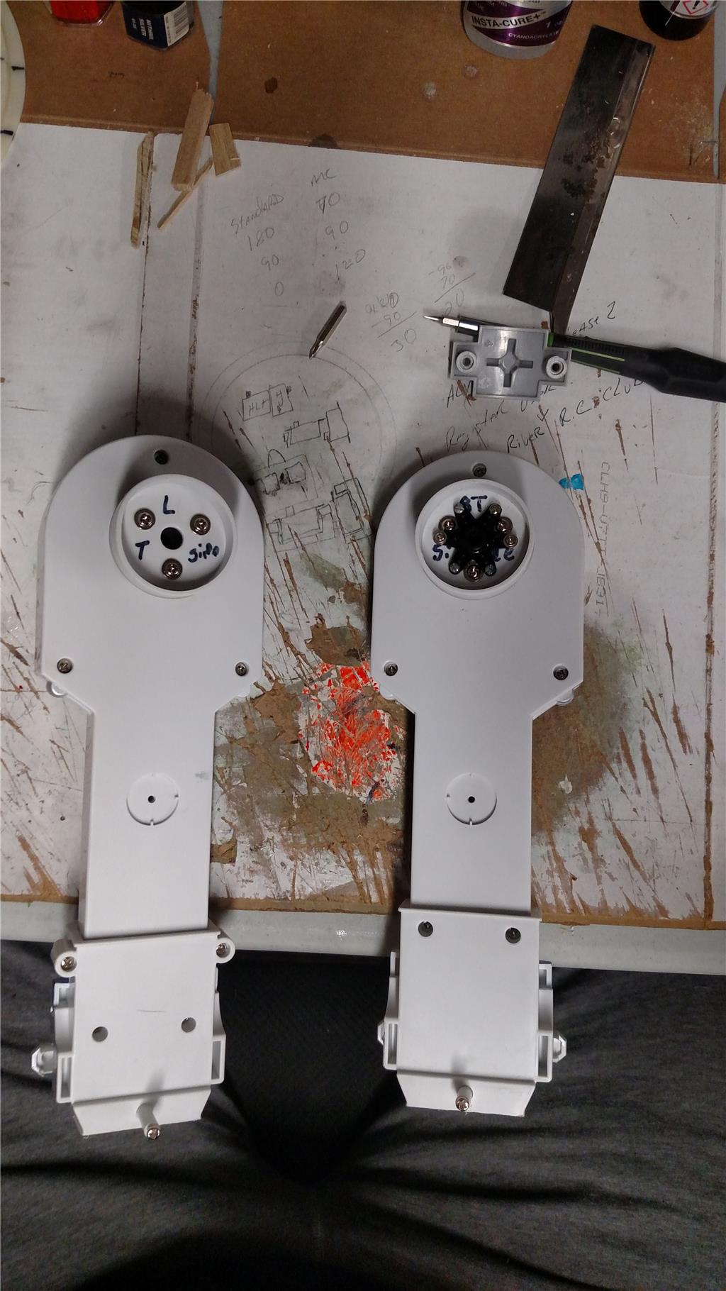
@AndyRoid or anyone that has used this R2 unit for a project did you by change take photos of the inside of the leg & ankle & foot before making any modification ? I didn't and with adding the continuous servos in both feet already I have missed my chance. I will add photos of my feet and how I set it up later tonight.

To make the "Bouncing" action, it looks to me like you would cut out a leg cross member that it stopping the plunger from moving, Also remove a screw, then add a servo to push/pull the ankle/foot up and down.

User-inserted image

User-inserted image

User-inserted image

#9  

The only pictures I took are on my project showcase. Maybe you could find one there. I deleted them from the computer.

#10  

I have completed the mounting and straightening of the continuous rotation servos for the feet. I have to complete the ankles for the rear feet before I can reattach the foot/ankle/leg together. I cut my feet off, as I wanted them to move back and forth with the leg movements of R2. This means that both R2 feet and legs will rotate from a standing position to a forward moving position. Also the shoulder joint with the connection for movement. I have also run 18 inch servo extender cables through the legs for the feet servos. That way there is plenty of cable to connect into the EZB V4.

I have built a front foot from balsa and an ankle out of hardwood and 1/8 inch plastic. I now have to build the upper ankle, that will connect the lower ankle to R2. I also have one of my brother-in-laws printing me the front foot and ankle based on @AndyRoid stl files.

Attached are photos of the rear feet with servos, the front foot and lower ankle. The legs with wiring, and rotation point at the top.

User-inserted image

User-inserted image

User-inserted image

User-inserted image

User-inserted image

User-inserted image

User-inserted image User-inserted image

PRO
Belgium
#11  

nice build.here a tip put the wire further away from the circle edge.see pic

User-inserted image

United Kingdom
#12  

@rsmith.

Cool, another R2 mod. Looking good so far, and nice job with the foot. Coming along nicely.

#13  

Thank you to both @Nomad 6R, and @Steve G. I will move the wire further away from the circle, I think I will lay it on the flat part or the wall. More to come.

PRO
Synthiam
#14  

This is a good idea! Having the legs move like that. I might have to copy you:):) :)

#15  

Thank you DJ. Please copy if you like.

DJ, I have a question for you. I would like to use a Y cable between a single port (D5) to connect both the leg servos to. That way I only have to address one port to get both legs moving in the same direction. Can the Ez-B Robot Controller V4 handle powering both servos from a single port ? The servos are the standard EZ-Robot HD servos.

#16  

Update 02/15/2018 Well let see what have I done in the last 5 or 6 days. I have moved my camera from the front holo projector to the radar eye. I have also installed a servo and custom mount for the camera so that it can point up/down. (thanks for the idea @DJ) See the photos below for that custom mount. I have also managed to cut/drill through the dome material and have one of the dome door almost ready to function. I have used my past knowledge of Radio Controlled Airplane building to get this dome door to move. I used an airplane aileron hinge to hold the door to the dome, then a control horn to physically make it move. As you can see from the photos the clear servo is what I am using for the door. Its a feather lite HiTec HS-45HB servo. Nice sub micro servo that is very light, 28ox or 8 grams. Its output torque is 13.88 OZ-in (1Kg-cm). it is inexpensive. I have also got the dome rotation finished as well. I finally gave in and did it like the others with a center mounted standard servo and a straight bar to the dome. I have gotten the EB V4 mounted in the torso and the Arduino Uno R3 mounted in the torso. The Arduino is running the LED as the things that I tried with the EB, just didn't work out for me. I reviewed the PWM to flash an LED tutorial, even used the provided code.

User-inserted image

User-inserted image

User-inserted image

User-inserted image

User-inserted image

User-inserted image

User-inserted image

User-inserted image

#17  

Update: 03-02-2018 Have gotten the 1st of 5 dome doors operational. It looks ok, but needs a paint job. I am now working on the door in the torso, just to the right of the vents. I have also mounted one of the leg rotation servos and have gotten it working. The leg is very tight so the servo is constantly humming. I will be working on loosening up the leg so that the servo use less torque to turn the leg. The two youtube links are for the videos for the dome door and the leg movement. I am also working on getting the feet mounted to the legs so that they will move when the leg rotates. I have gotten the MP3 trigger sound board installed and working good, to completely put it in R2 I need an amp and small speaker. Got my power switch installed and wired. Got my 3D printed front foot from @AndyRoid STL files. It printed out great. Working on the second dome door and one of the doors in the torso. See the youtube video (link below) for other updates. I moved the wires in the leg away from the circles. Thanks to @Nomad 6 for that tip. That's it for now.

User-inserted image

User-inserted image

User-inserted image

User-inserted image

User-inserted image

User-inserted image

User-inserted image

#18  

Update: 03-13-2018 Had an epic fail this morning. I have gotten to the point where I was ready (so I thought) to test R2D2 physical movement. I got him up on all three feet and then the legs would not tilt backwards. So I physically moved them to the right position, then I put him on the floor. Started the continuous rotation servos moving forward and on leg move to the center position due to the servo, and the other leg the wheel just spun. I knew there would be some issues. But really ! Anyway I have to move the continuous rotation servo wheels down toward the floor, so that more of the wheel makes contact with the floor. Have to get the foot tilting movement to keep the foot flat on the floor when leg is tilted back, and have to tinker with the leg tilting servos for a better mounting solution. Currently they do move a little and that is the issue with the legs not tilting. No video of the fail, but a couple more still photos of other items that are mostly completed.

If anyone has suggestion please feel free to let me know. Always looking for good idea's.

User-inserted image

User-inserted image

User-inserted image

#19  

Update: 03/16/2018 I am done reworking leg servo mounts, the connection between the leg, ankle, and foot. I finished the right leg then put it on R2 and tested it. The leg tilts as expected, although with a lot of servo noise. It must be having trouble with the weight of the foot. I have to release the servo or press the panic button to cut the power from servo. I also need to clear a little more material away from the feet so I get the proper tilt when the leg is back in position for 3 legged movement. I have also finished the left leg, ankle, and foot. Set it up the same as the right one. @AndyRoid I borrowed your idea about putting the servos on the foot floor. It seems to have worked out better, as I have a lot more wheel touching the floor. I now have to adjust the front leg/foot to lower it down to the floor by 5/16th of an inch. Once the front leg/foot is completed (tomorrow) I can test him to see if the physical movement works. I have to come up with some type of connecting rod from inside the leg to the foot that controls the tilting of the feet when the legs go backwards. I saw this rod setup on a full size R2 and it worked great. The feet were stable no matter what position.

The photos below are to show the pieces I came up with (look similar to the full size R2D2) to allow the ankle and feet to tilt.

User-inserted image

User-inserted image

User-inserted image

#20  

I've got a question, where would someone connect a mic to the EZ-B to take the place of the computer mic ? With my R2D2 project I will not have the computer around for voice input. I have purchased this mic (MAX9814) with build in amp and adjustable gain. Any help would be great.

PRO
Belgium
#21  

there are some speaker to get that works as a speaker and mic same time, excample the NAO robot and ez robot has the loTINY with speaker connection. maybe thats something you can try,just gessing.

#22  

Well it has been some time since I have posted. I have rebuilt my leg/ankle/foot assemblies 3 time now strengthening and adjusting it each time I rebuild it. I have finally gotten almost all of the tilting/angling out of the leg/ankle joints. I have seen an issue with using just wood for these joints. The wood mounts where the ankle joins the foot were getting crushed by over tightening the screws. I have resolved that issue by placing 1/16 inch plastic in front of all the wood mounting areas that use screws. Works like a champ. See the photos for more details. I have also added a 3rd working dome door on R2's head. Only 2 left to go. These are the ones with the periscope and the LFS (Life Form Scanner) I have found some linear servos that are strong enough for this task. They are $70 each, I haven't purchased them yet. I also need a PIR sensor from ADAFruit for the Wake on Movement function. I should have this sensor next week and can get that programmed. I have been working on the 2-3-2 transition. Current my R2 will go from 2-3 good but when I go from 3-2 he falls over. I have added a battery tray to keep the battery from moving and he seems much more stable while standing. See pictures for the battery tray. I still need to design and construct the slide assembly for the center foot. Currently the center foot is stationary in the down position. I have the programming worked out, just don't have the assembly built. That's it for now. User-inserted image

User-inserted image

User-inserted image

User-inserted image

User-inserted image

User-inserted image

User-inserted image

PRO
Belgium
#23  

very nice build.did you use the little metal tubes for the rubber in the servo, where the screw go's in?

User-inserted image

#24  

Thank you @Nomad 6R . I sure did. I put these in upside down. The rim is on the bottom so as to spread the down force to a wider area of the wood. This helps to prevent crushing of the wood.

#25  

Update: 05-24-2018 The biggest problem I am having is getting R2 from 3 legged mode back to 2 legged mode. When I do that movement R2 will fall over either front or back wards. I have added some rods from the feet to the shoulder, that tilt the feet either front or backwards. However my original design didn't have a fixed point to "force" this movement to occur. Without forcing this movement to occur, the feet do not properly tilt. I am in the process of getting this worked out. Since I an using a 6 point servo are for the leg movement anyway, I am going to us that as my top fixed point for the feet movement. My legs rotate backwards on both sides, that means I can use the rotational movement to "force" the feet to the correct tilt for either a standing position or a walking position, in theory.
User-inserted image

This first picture is my original design. The bottom of the rod is stationary and the top just slides up and down. That caused the foot to partially move in the proper direction. The second photo (marked up) is a concept photo of the new design. I hope this will resolve the issue. The guys that make the full size R2's sometimes use these rod. That is where I got the idea from, Astromech.com. There is also a midwest R2D2 builders club. User-inserted image

Another batch of electronics will be here on Tuesday 5/29/2018. This batch will provide me with the 3W LEDs that I am using for the holo emitters and a 5 volt board that will run my 3 ultra sonic range finders, and the PIR sensor for motion detection during sleep mode. The range finders are for the autonomous mode. I have to start on that programming soon. Since my Arduino controls the LEDs in the dome, I will be interfacing the 2 controllers and stopping the lights program on the arduino to simulate sleep mode. That's it for now

#26  

I was searching the internet looking for better ways to do things, when I can across this Thingiverse post about a rotating shoulder for the 18" R2D2.

Jakks Pacific 18" R2-D2 Mods

This @outcastrc had come up with a design to allow the legs to pivot from 0 to 36 degrees. Within the same post he has some ankle for R2D2, so that you can remove the feet from the legs like I did and then insert these ankles. I am having the ankles printed as we speak. They will be completed tomorrow. I want to check the quality from the place that I am having them printed which is why I did just the ankles. I also found out that this 18 inch tall R2D2 is a very close 40% scale of the full size R2D2. This discover alone will allow me to 3D print from any of the plans that I have found at 40% full size. This will allow me to add a number of neat items to my R2 to help his realism.

PRO
USA
#27  

Is 2 legged mode just for standing or do you plan to have him move also? If it is just for standing, I would retract the foot servos in 2 leg mode. Easier said then done.

#28  

@rz90208 2 Legged mode would be just for standing at this time. There is no room to have the servo's retract so the wheels are completely inside. It sounds like a good idea, but just don't have the space. At some point in the future I might have him "bounce" around in 2 legged more.

Yes you are correct about the easier said than accomplished. I am having enough issues with his legs and balance. Going from 3 - 2 legged mode. Although I believe that once I get the new shoulder and ankle joints are added into R2 that problem should correct itself. Somewhat. One can only hope.

#29  

I picked up the new R2D2 ankles. They look great. I had them printer at the 3D print shop at the University of Michigan, I work here. Below are some pictures of the new ankles. I am going to get the shoulders printed next week and then put all the items into R2 at the same time. These should also help my feet not to pivot right to left.

User-inserted image

User-inserted image

User-inserted image

User-inserted image

PRO
USA
#30  

I have this bot also and my solution was: User-inserted image

PRO
Belgium
#31  

thats a cool robot R2-JD2

#32  

I like your bot ! Get the stability wasn't a problem for you @rz090208. I like the base that he is mounted on and the arm are sweet. I have been looking at that base to start building a WALL-e robot. However I need to get my R2 finished. I will have some additional videos up toward the end of this week.

PRO
USA
#33  

@Nomad, I love your Idea for his name R2JD2 that is awesome. I have been calling him FUD2 DJ had mentioned he looked like a Minion do R2-Minion @RsSmith The main reason I went with the track base was with the legs, the body was always tilted up and his camera even with it pointed as far down as it would go still could no see the floor. So navigation was almost impossible. Also the rubber wheels did not work so good on any sort of carpet. How R2 managed to maneuver on Tatooine is beyond me. I am currently working on a new version with longer legs so as to keep the body always straight up and down.

#34  

When I put the camera in my R2 I have it so that it can move up and down. When I tilt the legs back to walk around I can shift the camera down to see the floor.

User-inserted image

If you look at his large black circle (eye for lack of better terms) you can see the camera and the slot cut out from top to bottom. I "borrow" this idea from DJ, R2D2 robot. This allows me the movement to use the camera when walking about. But soon, that will not be necessary as I am putting in ultra sonic range finders so that he can avoid things on his own. The wheels could be wider and then I would not have as much trouble on carpet. That might be an upgrade for the future. I still have a couple of major system to complete on my R2 before is will be called done. Then upgrades, so it will never be done.

@rz90208 can't wait to see your long legged R2.

PRO
USA
#35  

@RsSmith, I have my camera setup much the same as yours and I ended up moving the front foot to the back. but did not like the look. User-inserted image

#36  

@rz90208 I noticed from this picture you had/have an ultra sonic range finder in your R2. How did that work for you ? I am planning on using 2 of them mounted in the skirt to help my R2 with his obstacle avoidance so he can have an autonomous mode. Is that how you used yours ?

PRO
USA
#37  

@RSmith Yes, but the beam on them is wide so for obstacle avoidance they work good, for navigation not so much.

PRO
USA
#38  

@RSmith Additional info. I have found that the sensors have a smaller beam if mounted vertical verses horizontal plus you can mount more in less space. Then reading 3 or 4 sensors you get a better of the size and location of the object. Here is one of my bots I was working with, I do not have a pic of the vertical setup. User-inserted image

#39  

Thank you @rz90208 for the additional tips. I will be using the range finders in a horizontal pattern. I will be placing 2 of them in R2 skirt so they overlap.

I am going to move the camera to a different spot. Like @rz90208 said you just can't get low enough view to drive from the camera. Sorry my mistake. Since my camera was knocked out at the office from crashing. I just need to find a really really good spot for it. I will post when I find a good spot. Looking like the vents, but not sure.

I have 3D printed items from a Thingiverse post about R2D2 shoulders and ankles. Below is a link to this post. So far this would have saved me a lot of time and effort with the ankles. Jakks Pacific 18" R2-D2 Mods

I got R2 home from the office yesterday and immediately tore him back apart to replace his ankles and as of Friday his shoulders. The new shoulders have slots for the connecting rods between the feet and shoulders for stability purposes. The programming items that need to be completed are the motion detect and the range finding. The motion detector is mounted already in the front power coupling circle, and I will need to drill holes for the range finders, then mount. I also have 2 more dome doors to complete. One is for the LFS (Life Form Scanner) and the periscope. I am having both the LFS and the periscope 3D printed.

PRO
USA
#40  

@RSmith A really good use of the ping ))) sensor is for a cliff sensor. Aiming down and a little forward to watch for a drop off.

I like what you are doing with the dome doors, when you are done post your stl files. I think I will add these to my R2.

cheers.

#41  

Update: @rz90208 I really don't have any stl files for the hinges for my dome. Each one is slightly different. I am trying to standardize on a hinge design, it would make life a lot easier. Once I standardize I will create the stl files. I have used all sub micro servos from Hitech the HS-55. I have gotten them for as little as $9 each as high as $11 each. The are an analog servo with a good amount of torque, therefore I figured they would be perfect for the job. They are some and fit almost any where. I have has to customize each individual dome door also. It depends on how I cut it out of the dome itself. I am going to see if I can shrink a dome door from a full size R2D2 to fit. Not sure how that will work out, as some 3D printed parts that I had a friend print (holoprojector parts) would not print at 40% reduction. Those parts will arrive tomorrow might so I can see what happened.

I also need to design a servo hold and pivot point all in one. See the photo of the assembled ankle and you will understand why I say that. Redesign will wait a little bit though.

Anyway I got the new ankle completely installed on the right side, and the new shoulder is half way installed. The main reason that it is half way installed is because I forgot to print a piece for the inner shoulder. Those 3D parts will be ready tomorrow. Hopefully I can finish the right side and start the left side this weekend. See the photo for ankle pieces. I will add shoulders as I finish the install.

User-inserted image

User-inserted image

User-inserted image

User-inserted image