
Ellis
USA
Asked
Moving Head Sound Detector
How do I get my sound detectors to give constant voltage readings on the ADC Graph? I am using the two detectors to see where the loudest signal came from then move the robot's head toward the loudest.
I have read all I can find on Synthiam including the Community and Tutorials but can not see anything that will solve my problem.
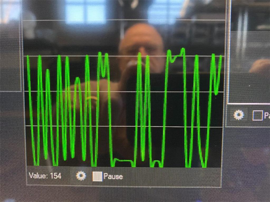
The problem is I can't get a consistent signal from in the ADC Graph. The line graph will jump up and down even with the a constant audio signal coming from my sound generator. Since their is no sound consistency I can't write script to make the head move.
Is my problem having to do with the wrong sound detectors or the way the information is handled by the Ez-Robot program?
Related Hardware (view all EZB hardware)
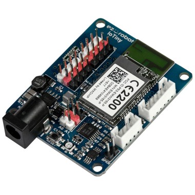
EZ-B Iotiny
by EZ-Robot
Control IoTiny with Synthiam ARC: 100MHz Cortex‑M4 Wi‑Fi IoT/robot controller-camera, servos, ADC, I2C and digital I/O for easy internet automation
Wi-Fi / USB
Servos
8
Camera
Audio
UART
✕
I2C
ADC
✕
Digital
✕
Related Robot Skills (view all robot skills)

ADC Graph
by Synthiam
Historical ADC graph and numeric readout (0-255) for 0-3.3/5V inputs; configurable board/port, sample interval, color, and pause for ezb controllers.

ADC Value
by Synthiam
Display ADC port voltage and 0-255 linear values (0-3.3/5V); configurable board/port, units, multiplier and sample interval.

ADC Meter
by Synthiam
ADC VU meter displaying 0-3.3/5V as a 0-255 linear meter; configurable board/port, sampling interval and color; pausable real-time readings.

I have two questions concerning sound sensor that have come up.
I am wondering if the wifi is causing variations with sign wave on my Ez-b ADC Graph. If you look at pictures at top you will see the difference between a sound generator and ADC Graph. The sound Generator provides a solid tone same height signal. It should cause the ADC Graph to show a solid voltage. What is going on? Am I wrong in my assumptions.
I am looking at doing triangulation Location using time difference to calculate location of sound. Where are the calculations of received signals calculated? Will this work with this setup or do I need to have an on-board computer to eliminate WiFi slowdown.
@Ellis
Yes, you are wrong in your assumptions Radio signals (wifi) and sound waves (sine waves in your case) are not even in the same ballpark as each other... I cannot see them interfering with each other
It's kind of difficult to understand what you want to do sometimes as you seem to not quite understand it yourself.... Saying that you are way over complicating things.... You can easily calculate where the sound is coming from (left, right, centre buy using 3 cheap sound sensors) and a couple of lines of code... However if your goal is also to calculate range from the sound source you will need to buy some expensive sound hardware and have ptp write code for you.... In other words, forget it and just use a ping(s) in conjunction with your sound sensors to measure range...
FYI 3.3v - 5v Sound sensor This one worked for me no problem....
Usually I aim for the most complex stuff and sometimes there is a simple solution for the problem and I miss the point
DJ:
and he pointed a control: I'm guessing the control captures a Stereo audio, compares the peak levels and determines which one (left, right) has the smaller offset so you can identify left,right as the origin. So Is not rocket science, is simplistic and I believe can work, if you understand the limitations of the implementation.Tony Elis: https://synthiam.com/Community/Robots/Altair-Robots-In-Servo-Magazine-294/comments Did something similar. He used simple sensors (analog microphones) and code a firmware in a PIC micro-controller to capture the adc levels and his firmware dispatches the feedback direction to the ARC.
If you want something out of the box I would recommend Sound-Movement control or Richard's idea.
If you want something more elaborated/fancy I would try a hardware solution: https://www.seeedstudio.com/ReSpeaker-Mic-Array-v2-0.html I believe there are some python scripts to grab the DOA angle, and other relevant information, but, you will need to take the risk of getting the board test and ask the vendor for windows support.
Sometime ago, I built something with Playstation eye cameras they have 4 microphones, and I've explored some sound algorithms on Linux, the idea was to have a cheap device Raspberry PI Zero with a PS Eye streaming audio plus DOA, and other stuff. I got mixed results, most of academic papers are complicated, and I forgot most of the college math, it was a pain and unfortunately during that time it seems not useful to me... I would love to port the code to windows, put the time is a constrain, and I spend most of my day coding so it's difficult to get the energy to code more.
I just whipped this up quickly and is untested... I am sure it can be done with fewer lines of code but I am multitasking at the moment... It is obviously meant to work with 3 sound sensors....
Thanks to all of you.
I agree with simple. I have been trying to make it simple but it hasn't worked. I have been using sound sensors for location. I have tried DAOKI Sound Microphone Sensor Detection Module and RobotDyn sound sensors both with digital and analog pins. I am using the analog pin. The response I get can be seen on the above pictures. The graph is all over the place. I do not know if this is the problem.
What really happens is the graph will jump from 0 to 64v instantly then right back to 0. This continues to happen but with different voltages except they mostly peak from 64-65 volts no matter how loud the audio is to the speakers. This is mostly a one volt variant. The information is useless to sense sound volume because you can not compare which microphone is louder.
This is why it looks like I am all over the place. All I want to do is collect sound from three microphones, use a program to process microphone info and make decision where the sound is coming from and turn robot head in that direction so it is looking at where the loudest noise is coming from.
Richard I will try the code. I looks good for finding loudest microphone. I hope the information I am getting to the app is the right info.
Thanks
I still feel like this is a gain issue. Because a sound should be louder based on the direction of the microphone. With no sound in the room, the microphone shouldn’t be returning much voltage on the adc wire.
I’m assuming the sensor shares a common ground with the Ez-b? And maybe it does require a pull down resistor on the signal wire? What’s the data sheet show?
DJ you might be right. I did adjust the gain to see if it would help it work. I will work on that some more. Also it does share ground with the sensors and it did not work with or without resister.
Also above Richard showed some script I am going to try and just skip the controls.
I will let you know how that comes out.
Thanks for your interest.