


Now I have the EZ-B kit and the Hearoid it's time to start my Showcase thread.
I still haven't decided on a name for him yet, all suggestions are welcome.
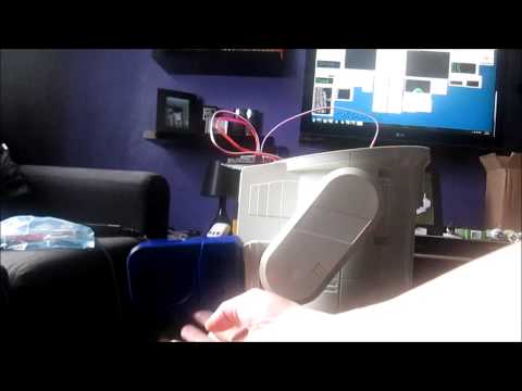
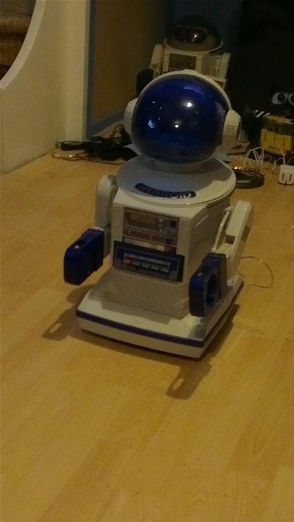
I won this robot on ebay weeks ago, for the past 2 weeks he has been waiting for me to collect him...
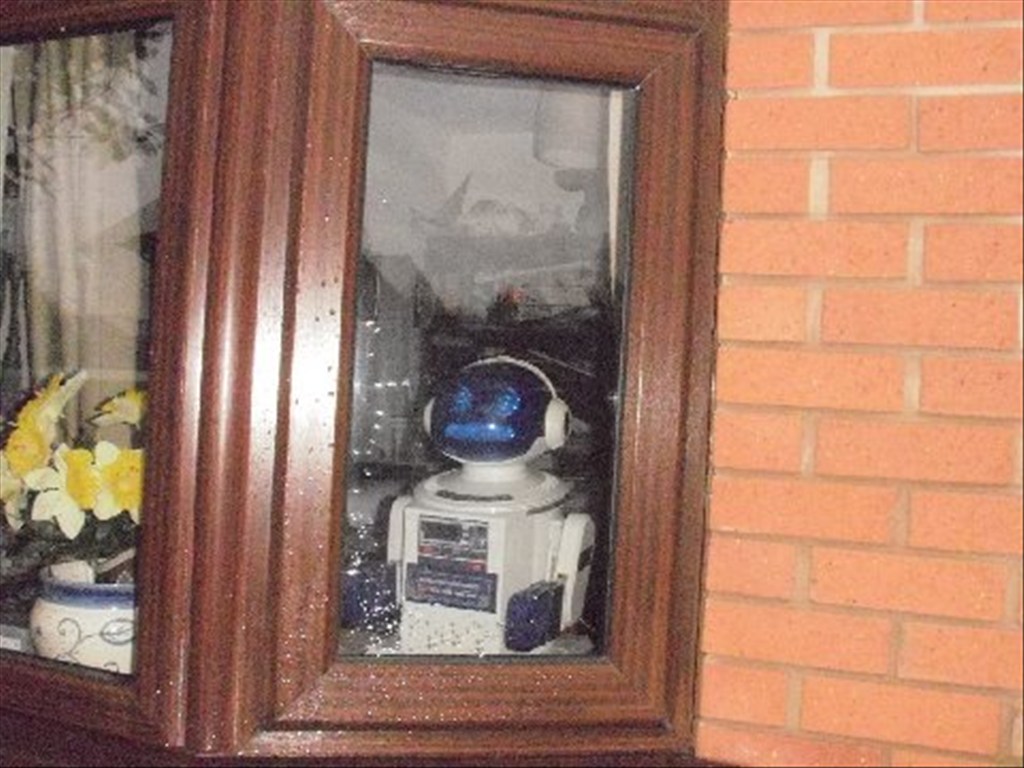
Today was the day, a road trip to pick him up and bring him back to his new home...
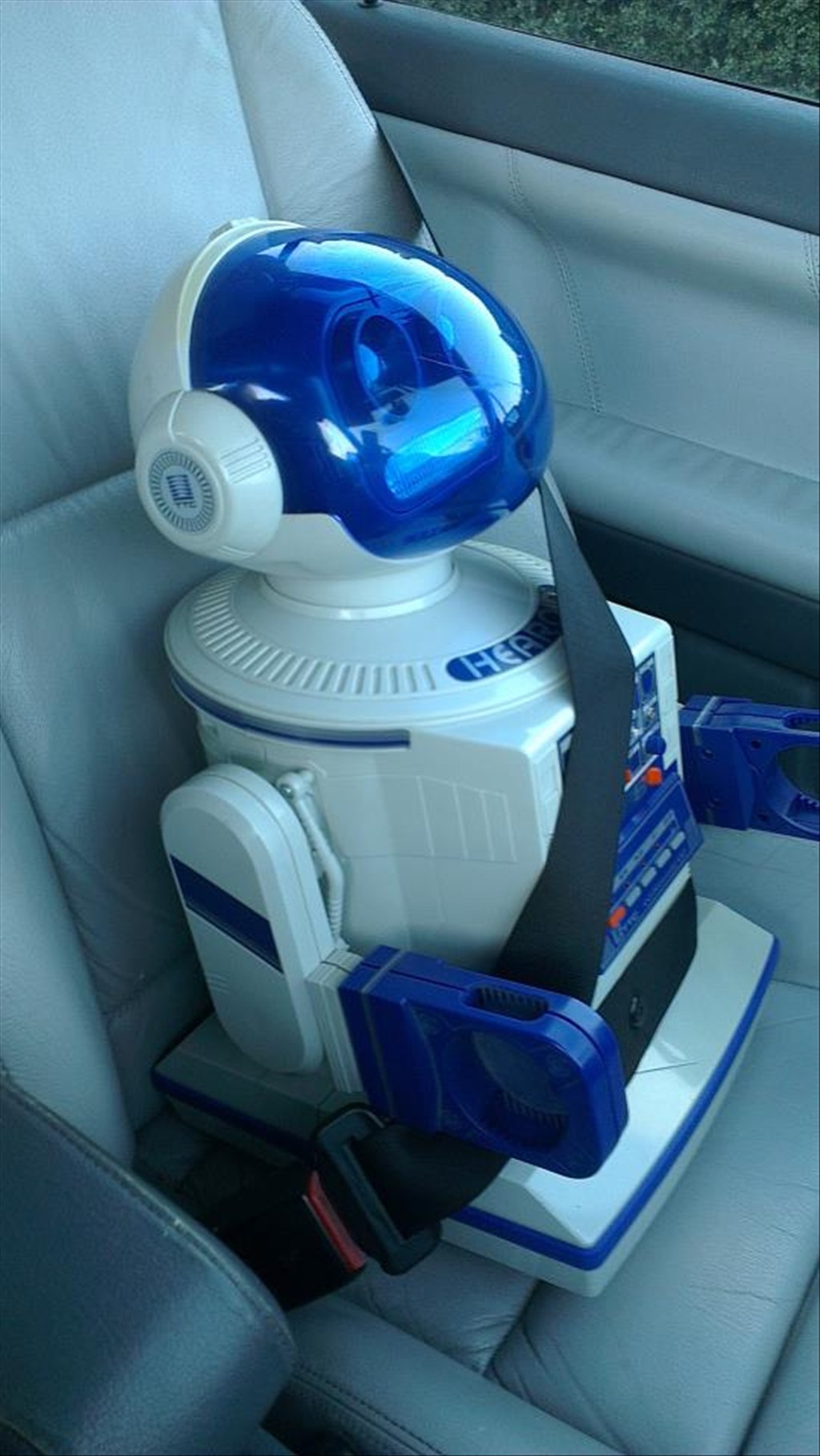
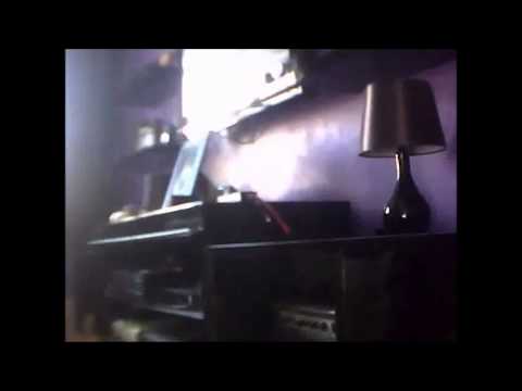
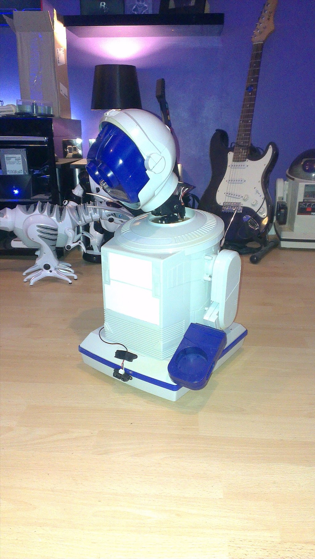
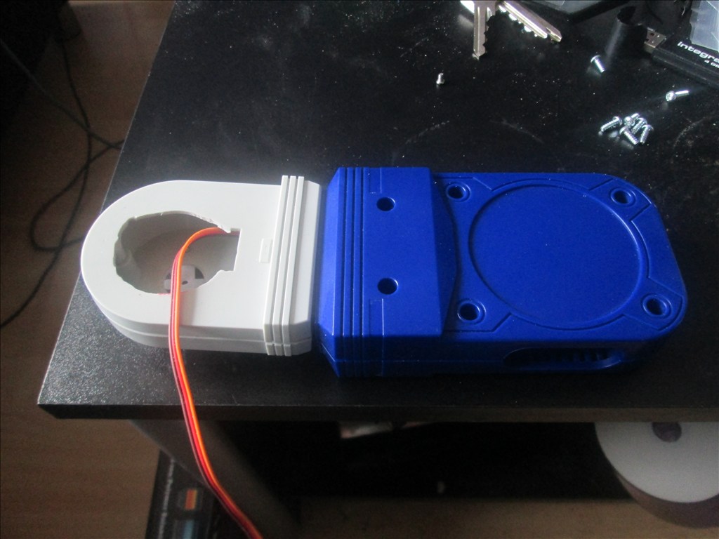
In his new home (with Omnibot and Wall-e in the background totally unaware they are next in line to be opened up)
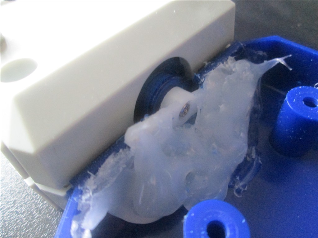
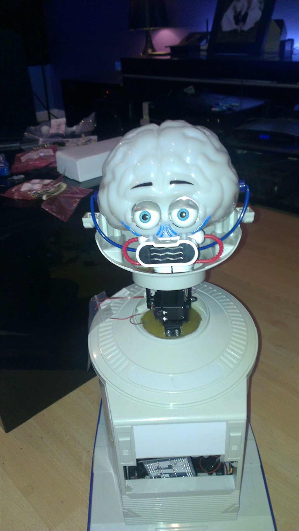
It wasn't long before this happened...
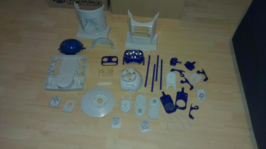
Now waiting to go in the dishwasher to get nice and clean.
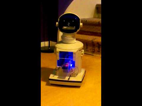
The plan is to make him autonomous, running 24/7 (except for when he knows to go charge himself up) but will also be adding in the various image tracking options.
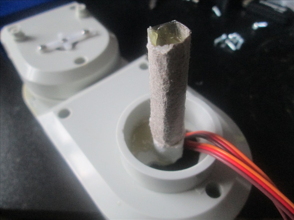
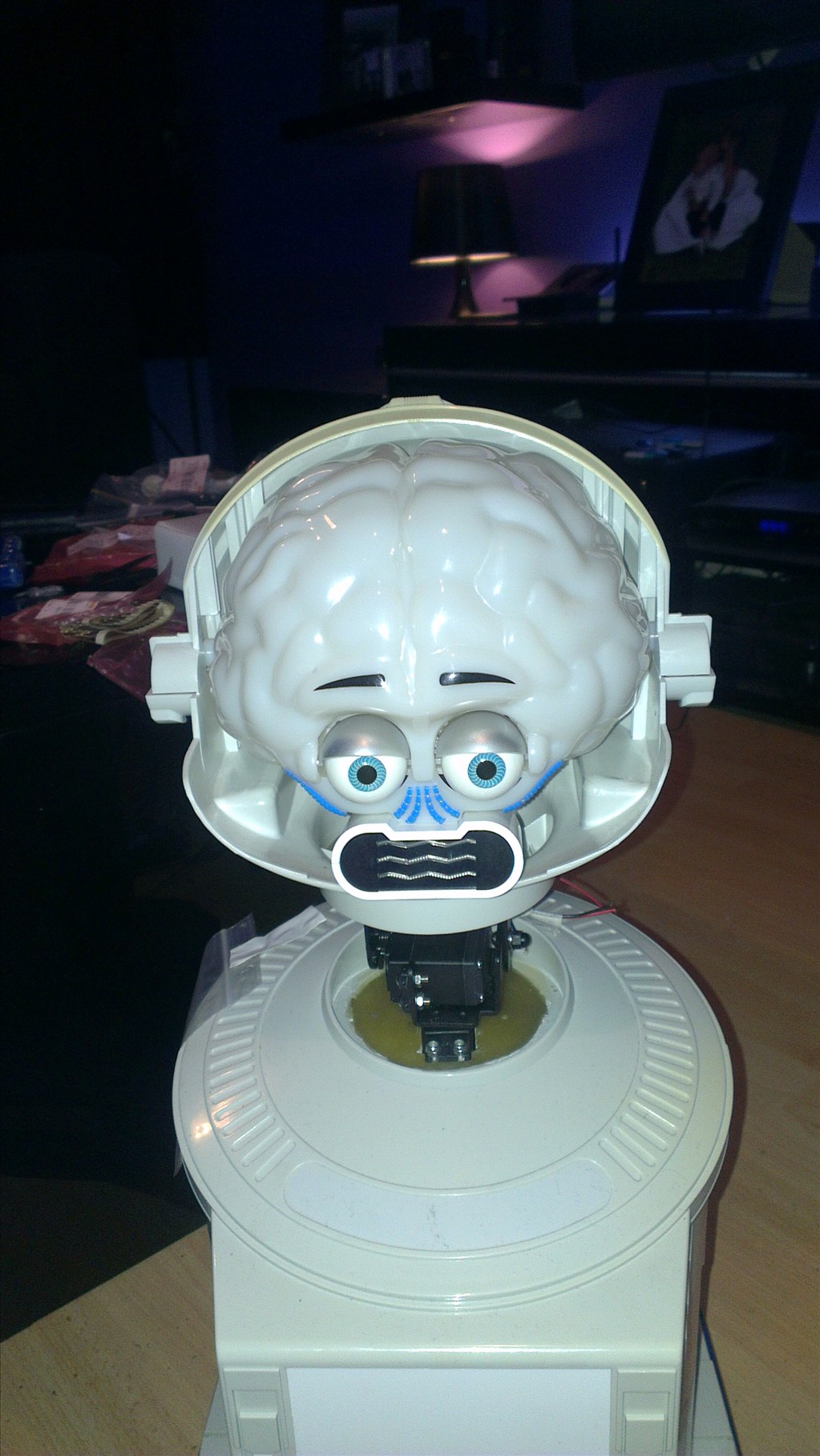
The only other slight modifications to be made to him are to convert the head to tilt & pan which will involve having to give him a small neck.
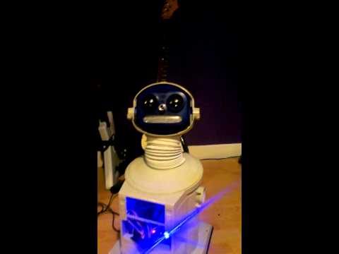
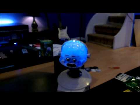
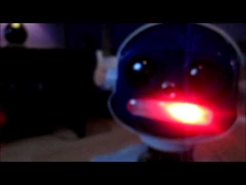
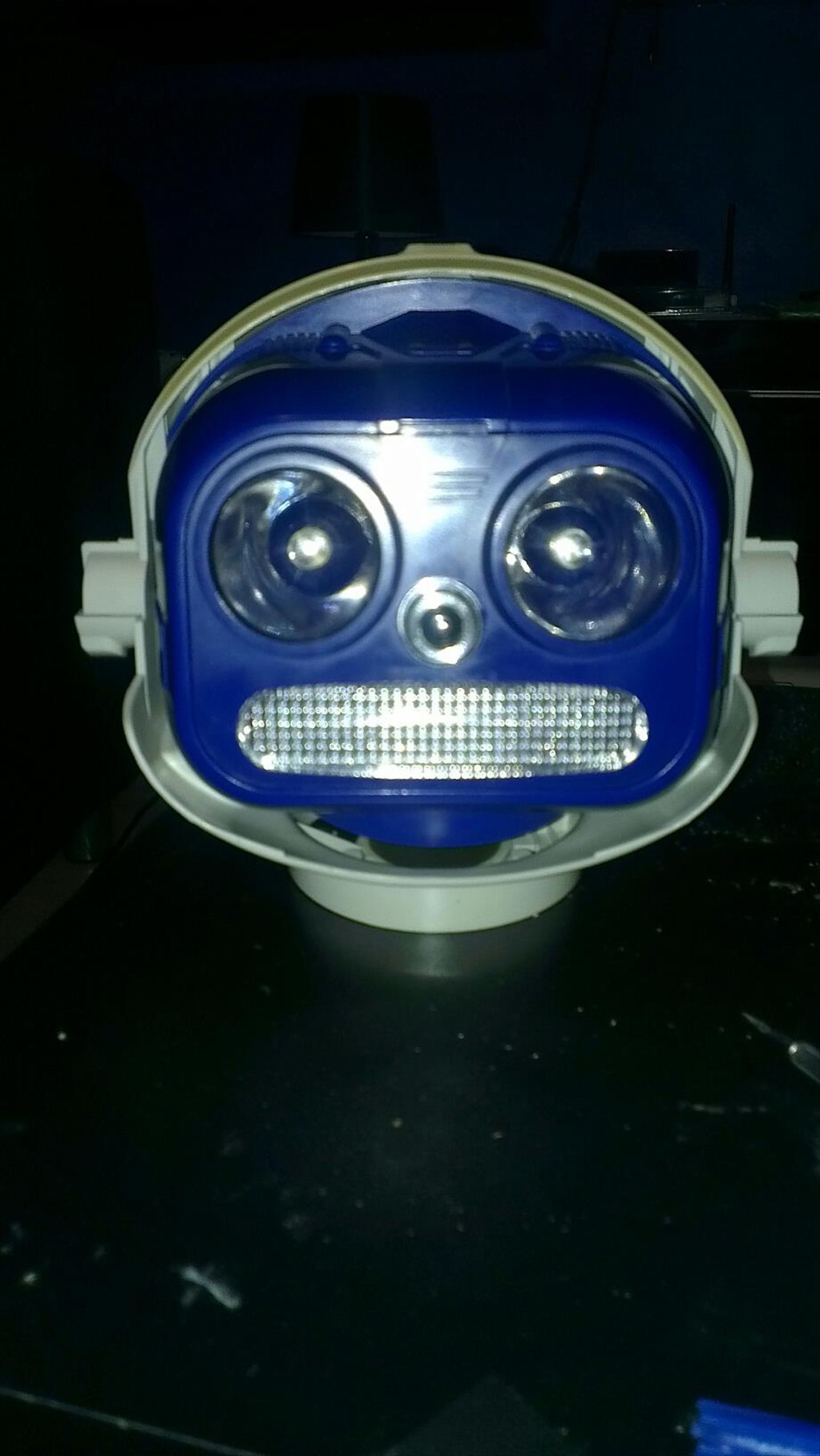
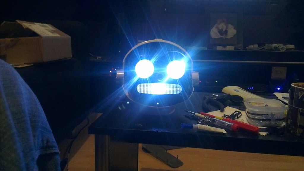
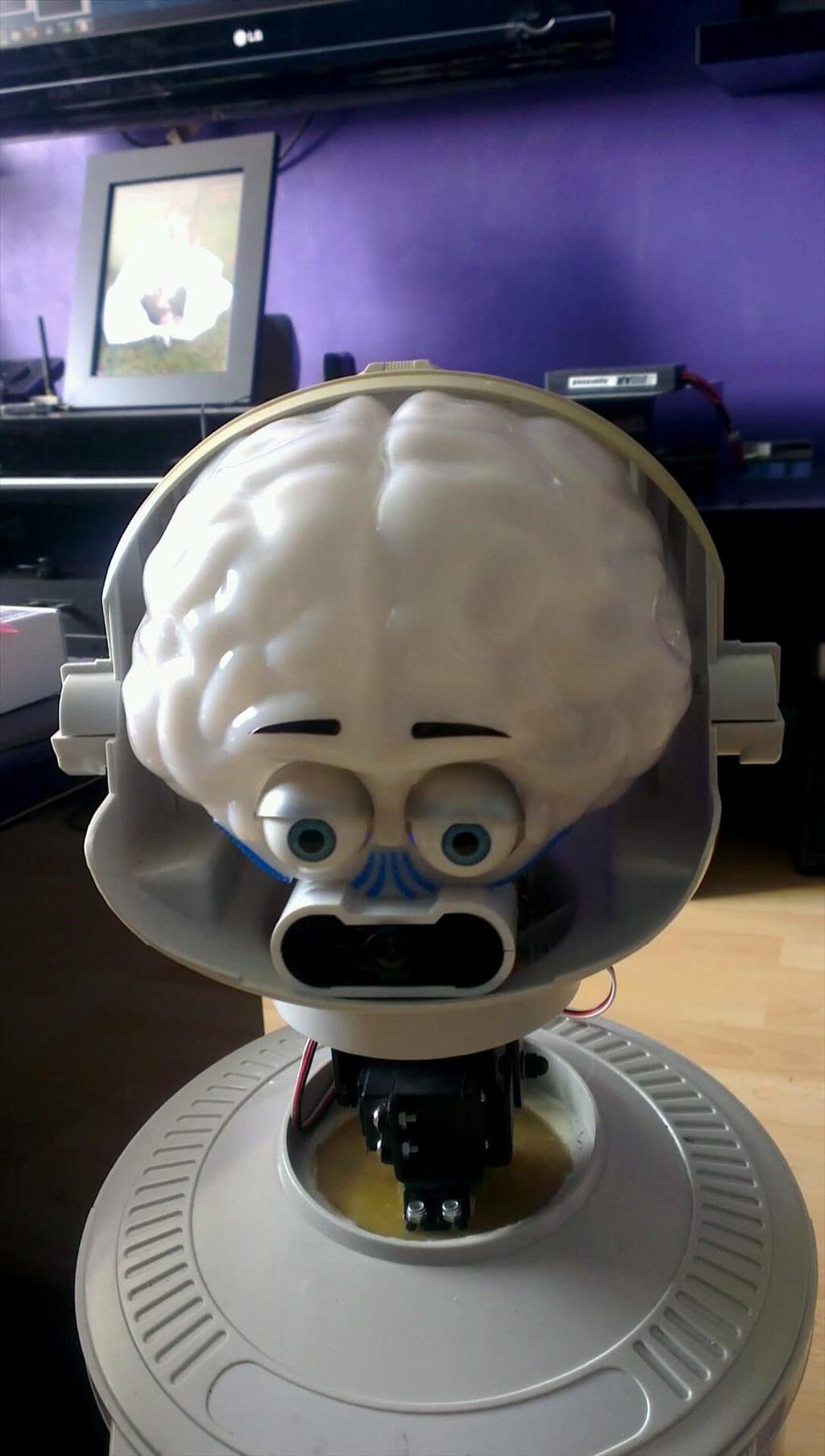
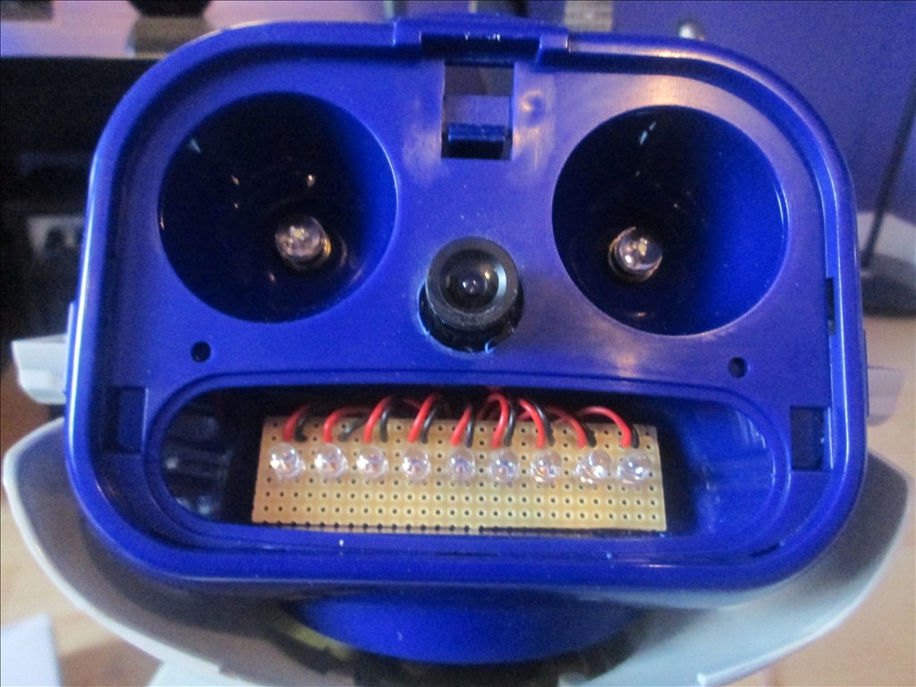
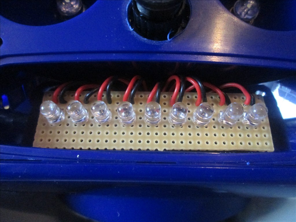
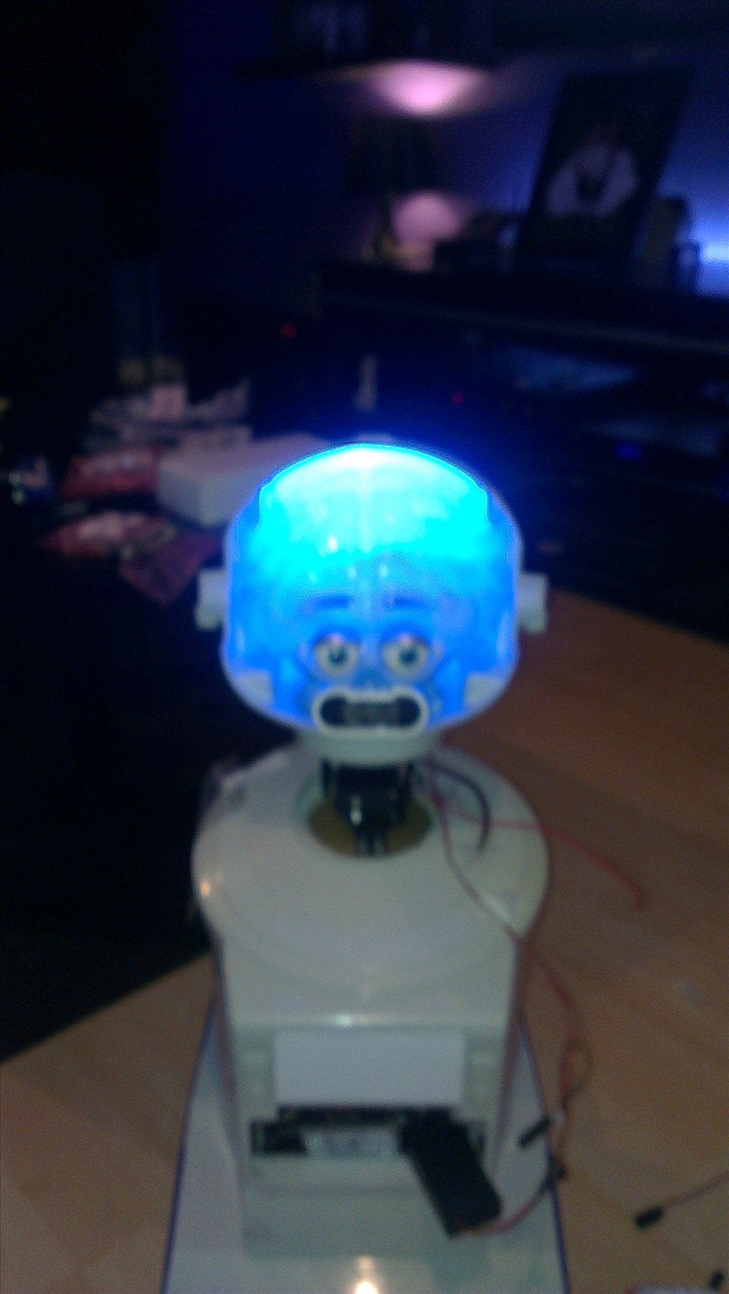
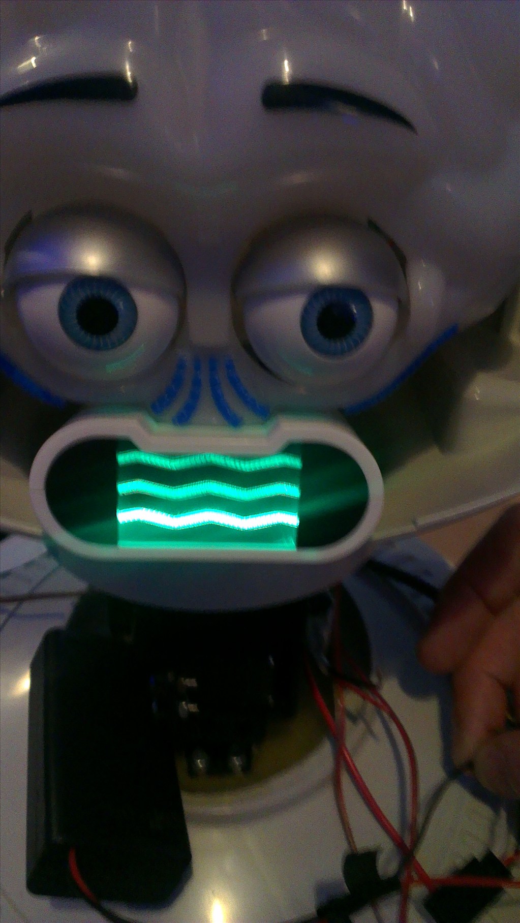
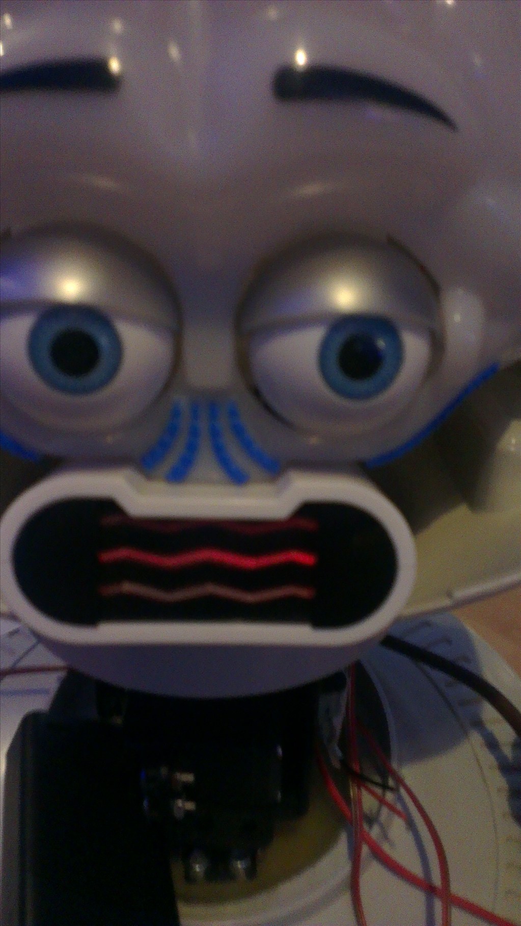
The head will include the camera. I haven't yet decided to fit it in one of his eyes or to make it his nose. The issue to overcome with this is the blue tint on the bubble head. The mouth will have a light or some lights in which flicker when he speaks.
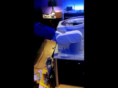
The arms will be given some life with servos at the shoulder joints and the elbows provided I can get them to fit in there nicely.
Ultrasonic sensor will be in his chest, probably on a servo to give a wider view.
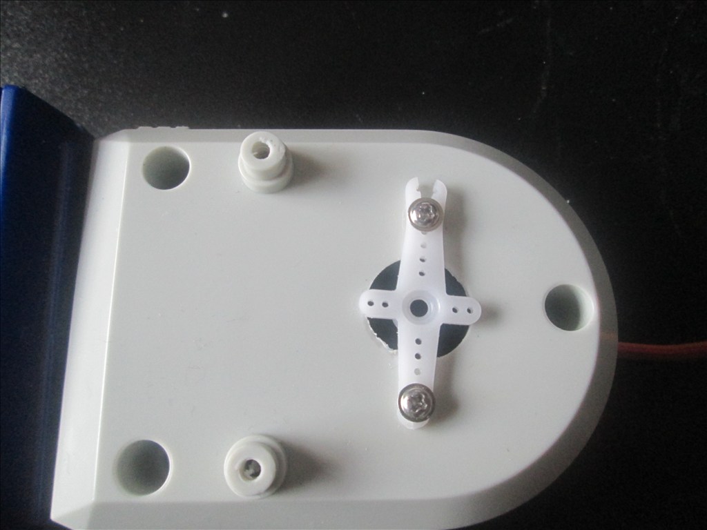
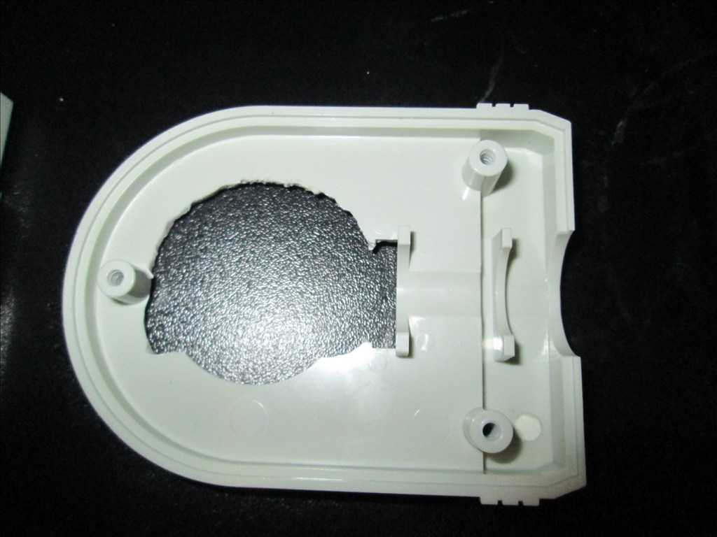
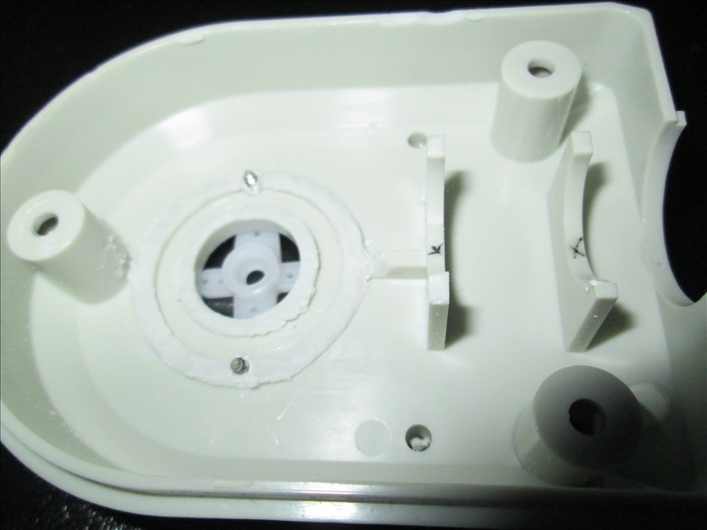
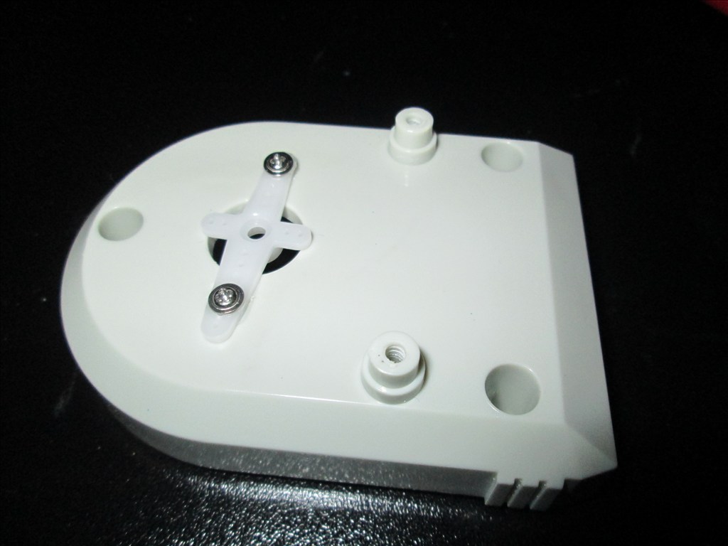
Original drive wheels and gearbox seem to be in very good shape so will plan to reuse those and just replace the existing motors for the modified servos if they can manage the task.
Speaker and microphone will be in the original positions - if it's not broke why fix it?
Not too big a project but enough to give me a test, help me learn and bring an old robot back to life.
Discover more robots
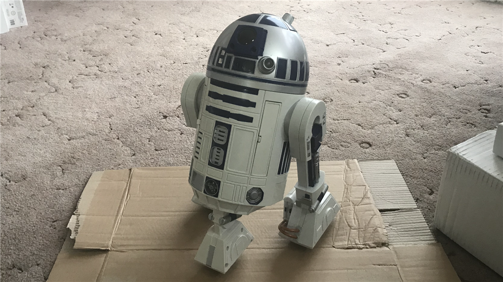
Steve's R2-D2 Hasbro Toy Hack
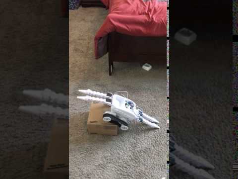
Faengelm's Roli The Climber


Your doing a great job! Don't worry about the range of motion. Most people only have about 100 degree of motion. My. Shoulders and elbows are 220 to 240 degrees range of motion because I surface mounted the standard servos and connected them with push rods. Its more than anyone needs anyways lol. Can you post exactly how you did your circuit for your lights to turn on and off? Could be a great wiki submission. Thanks bud! - Josh S
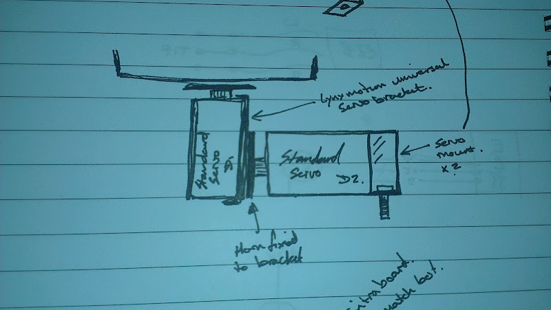
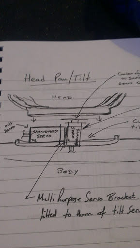
I'm undecided on the length of the neck at the moment. It was longer than that too but changed the pan/tilt bracket from using a lynxmotion long c to a short c slightly modified. I may, when I get chance, try just fixing the two servos together using the universal bracket and cutting a slot for the pan servo with the tilt servo fitted to the base...
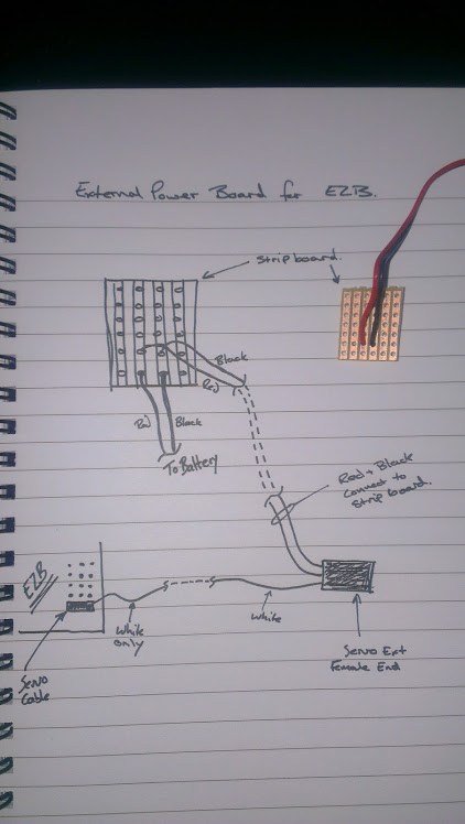
Apologies for the poor sketch and even worse photo of a sketch.
But then that would restrict the already restricted range (currently 50-70). I guess I will see how bored I get over my 2 week Christmas break.
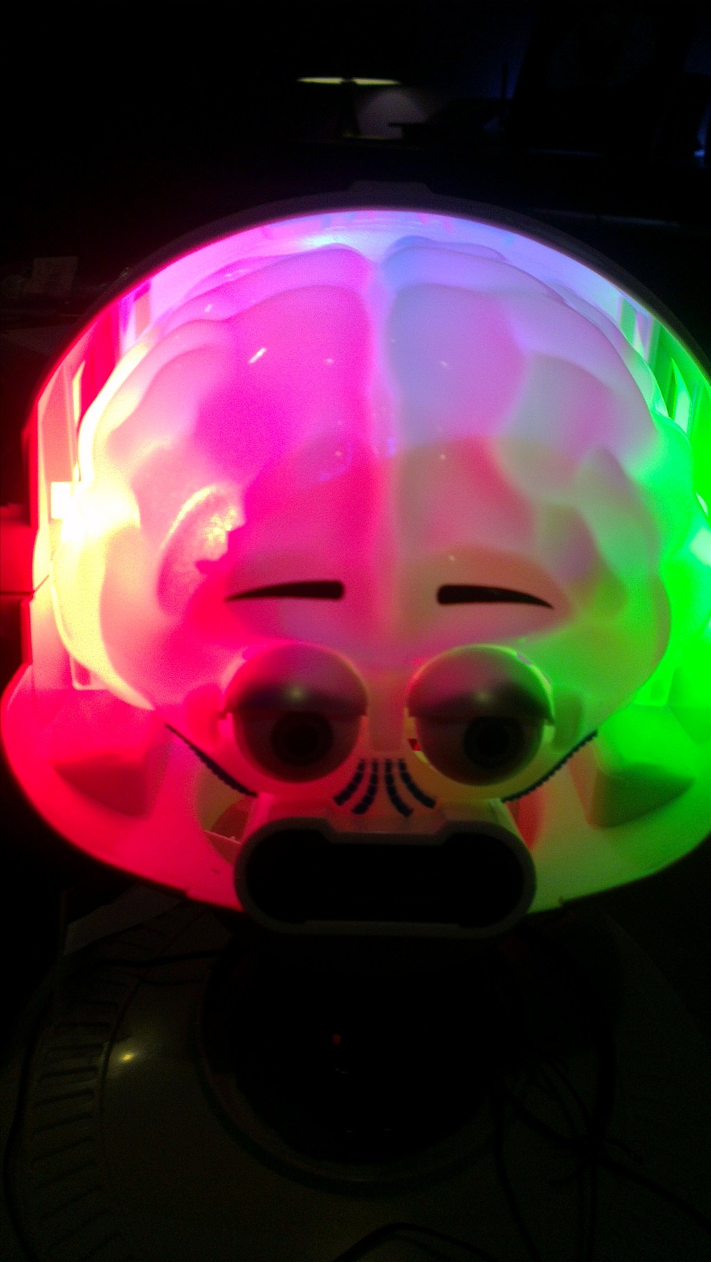
@Josh, I'll do a video when I do the third one (want the eyes to be switched individually).
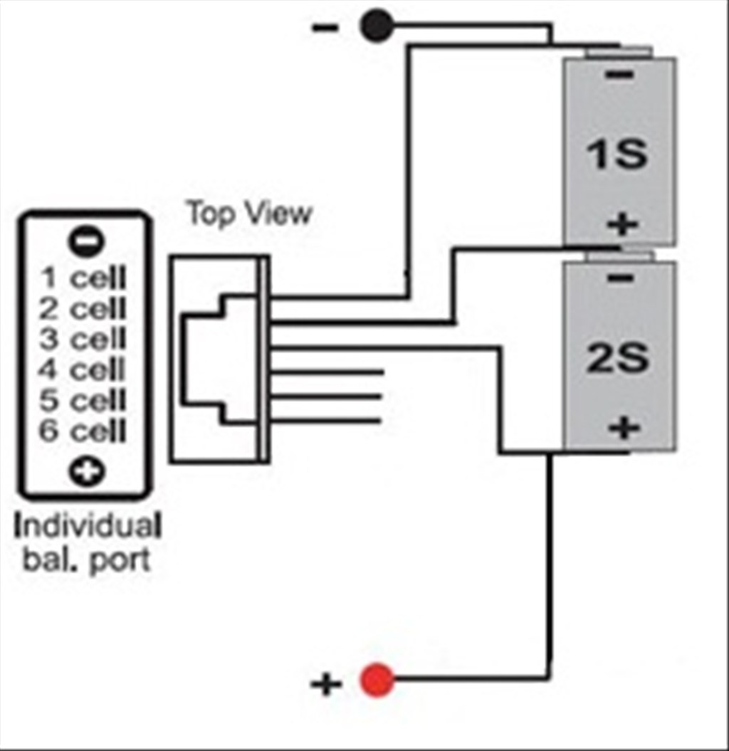
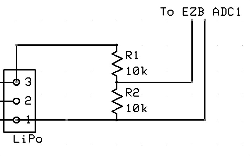
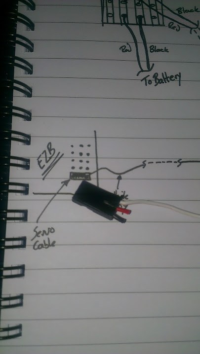
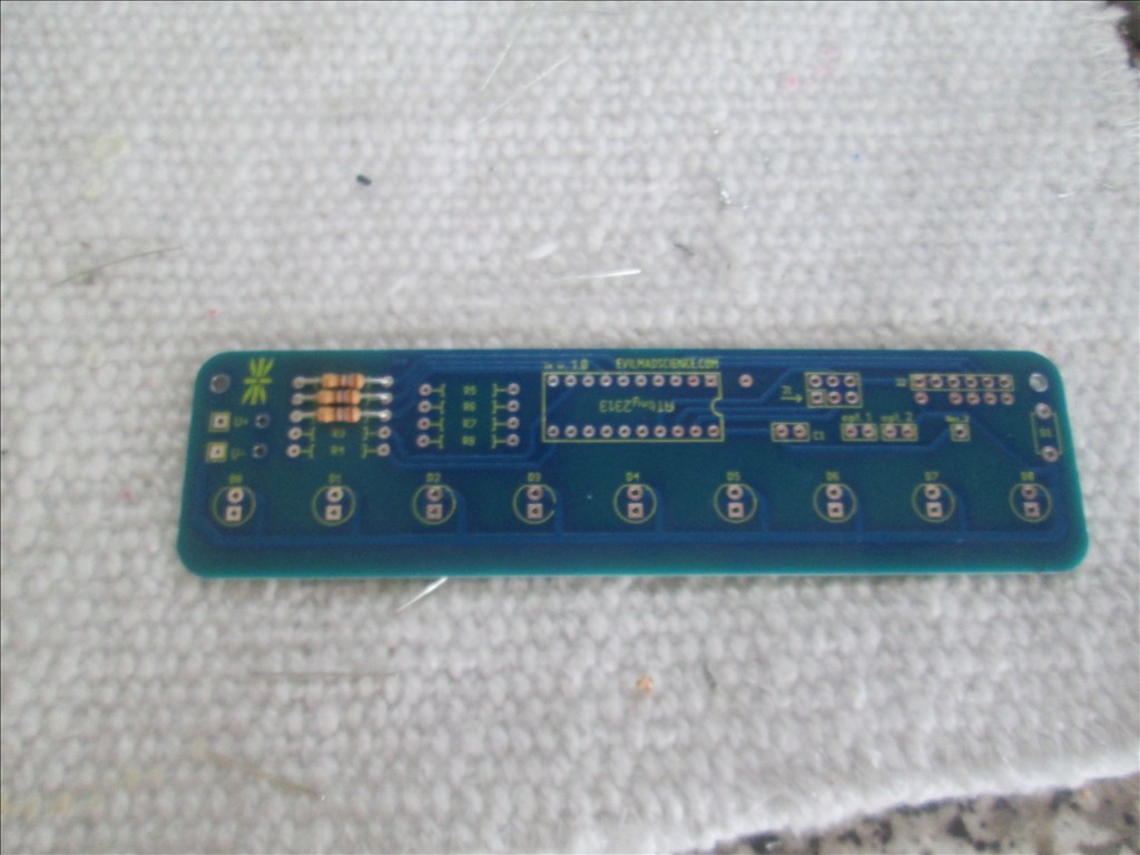
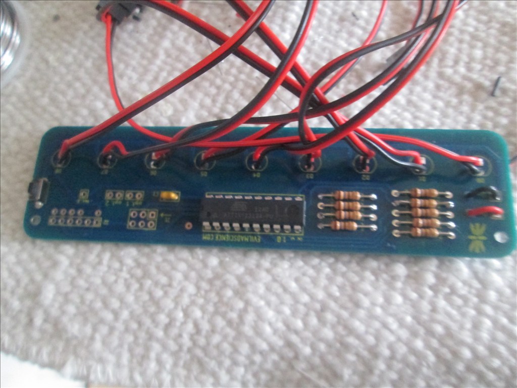
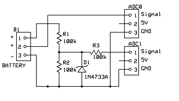
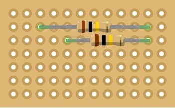
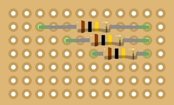
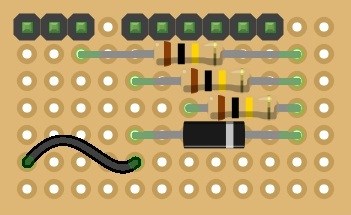
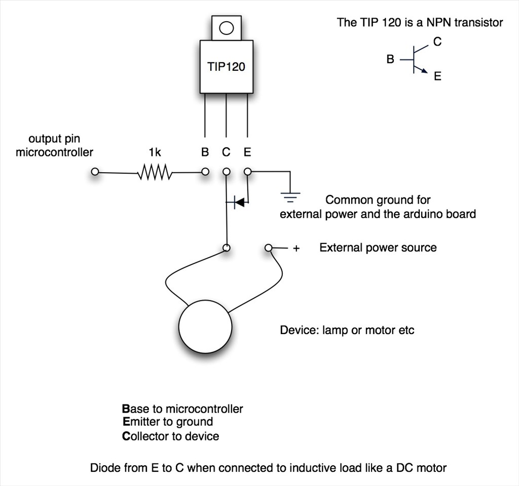
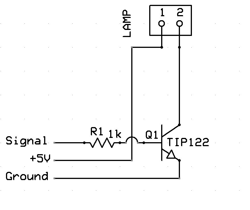
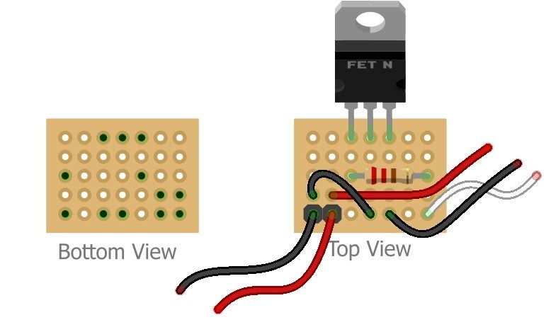
In the mean time, the schematic
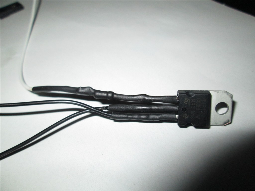
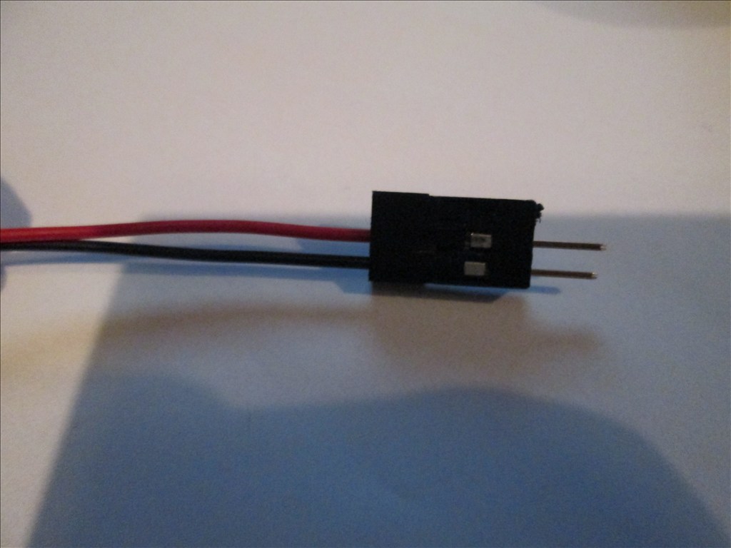
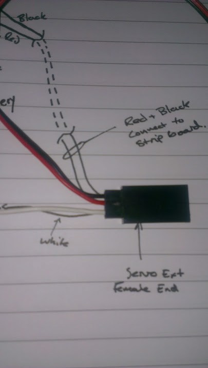
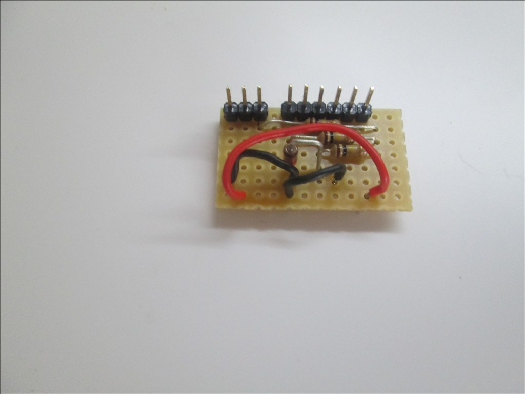
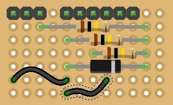
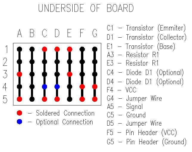
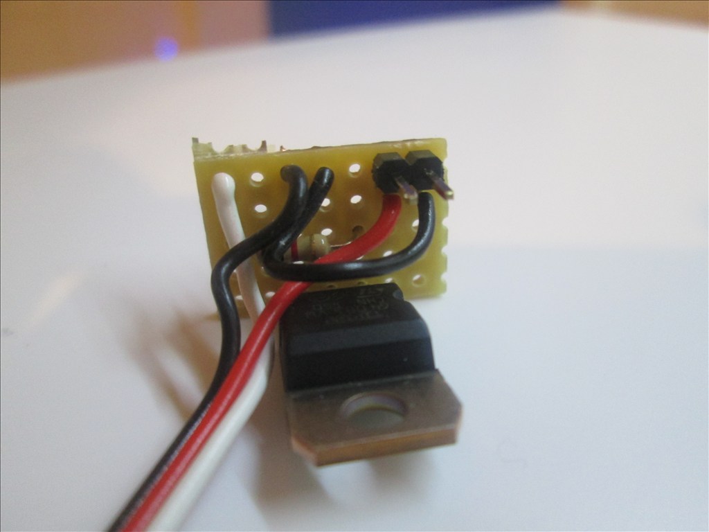
For ease I used a servo extension cable, pulled off the surround of the female end to expose the three pins. Cut the white wire, soldered it to the 1k resistor, the other leg of the resistor went to the base of the TIP122 Cut the black wire about half way, the half connected to the male connector (EZB side) was soldered to the emitter. The other half of the black wire went to the collector. The red wire was left alone. Using the existing plug on the omnibot wiring I plugged the female end of the extension in to the plug. All soldered joints were covered with heatshrink to protect against shorts.
If using LED lamps the eye circuit needs rewiring due to Tomy's weird way of wiring it up. Also pay attention to the polarity, the red wire needs to go to the positive of the lamp.
You may want to re-write that if it doesn't make sense, it's 4:30am and I've not yet been to bed...
Nice job! Excelent crafstsmenship. You must be giving your drummel a work out. I like the way you used a cable extension and used the end as a socket to slip over the resistor. Useing the remaining wires to complete the circuit was very neat.
Thanks for the schematic. Hope you get some sleep now.
Well I still haven't been to bed... had too much to do for Christmas so just stayed up all night (I'll pay for it tomorrow).
Just spent the past half hour playing with the arm again and unfortunately it seems the mini servos aren't man enough to lift the existing plastic hand (never realised how heavy they are). So I will need to revisit that after Christmas and see if I can find a way to make it work (claws are an option but wanted to try and keep it as original looking as possible).
I may try the possibility of fitting springs in the arms so that there is always a force puling the arm up to aid the servo on the up movement and hoping gravity plus the servo will be enough to pull the arm down. It's all ideas at the moment (so any others would be very much appreciated)
Yes my "dremmel" (cheap mini grinder set which was a quarter of the price of a dremme) is getting a lot of use and my kitchen is getting covered in a lot of small bits of plastic. My own fault for not wanting to go outside in the cold and wet to do it and as I live alone I have nobody to complain at me about it.
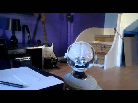
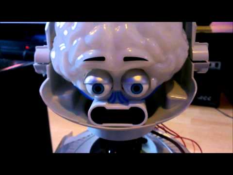
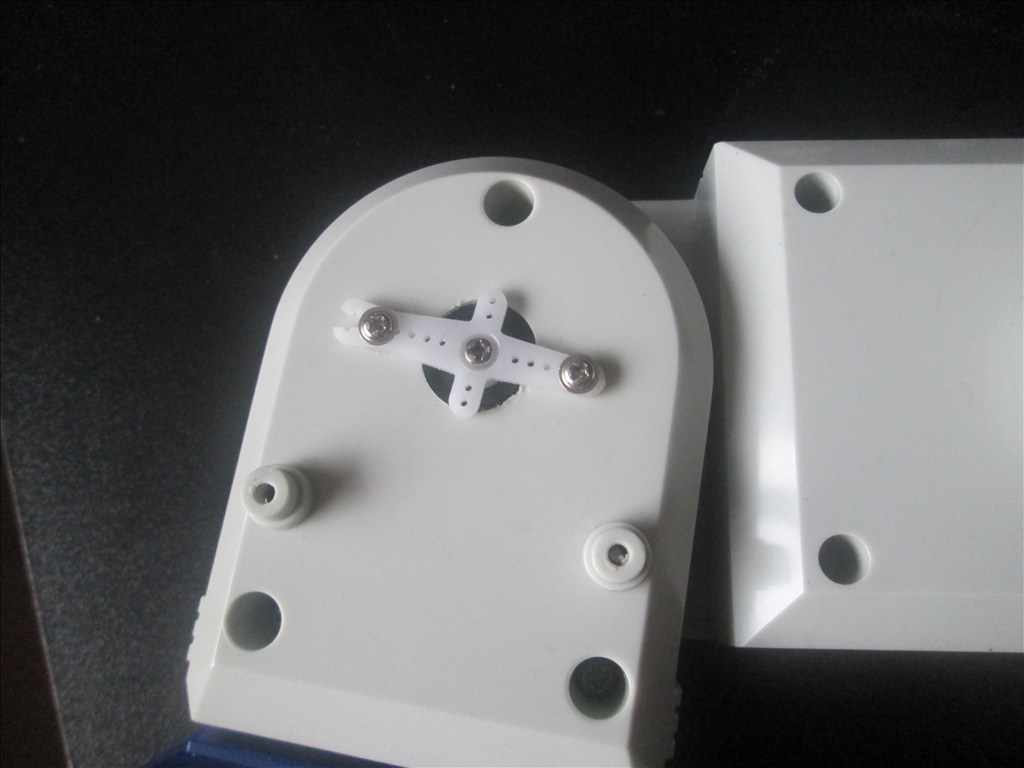
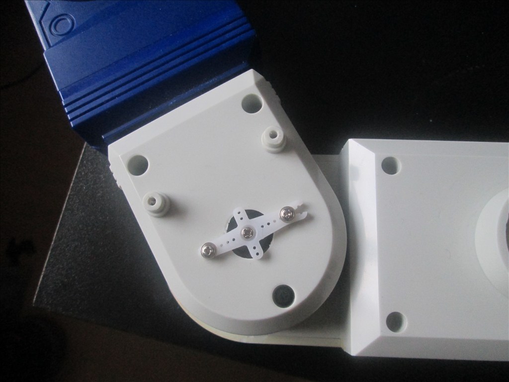
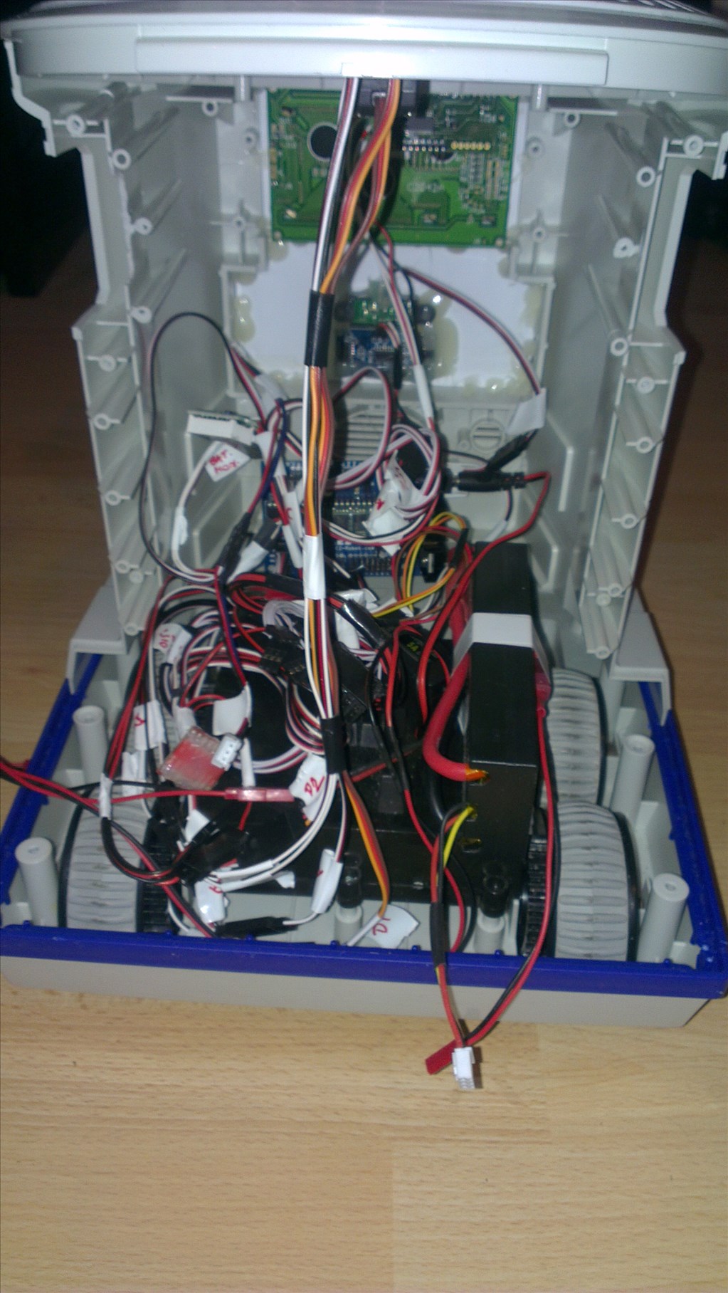
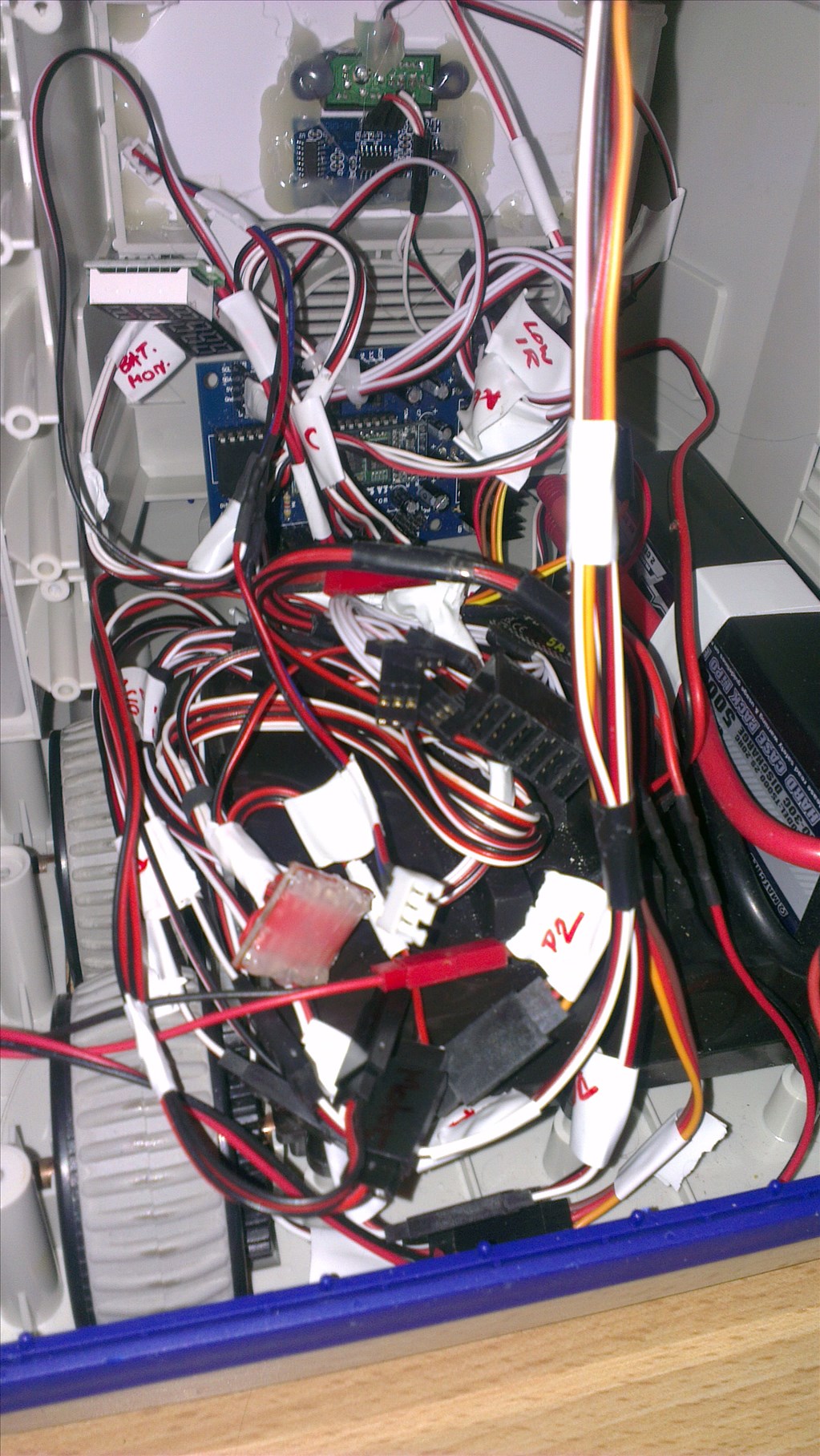
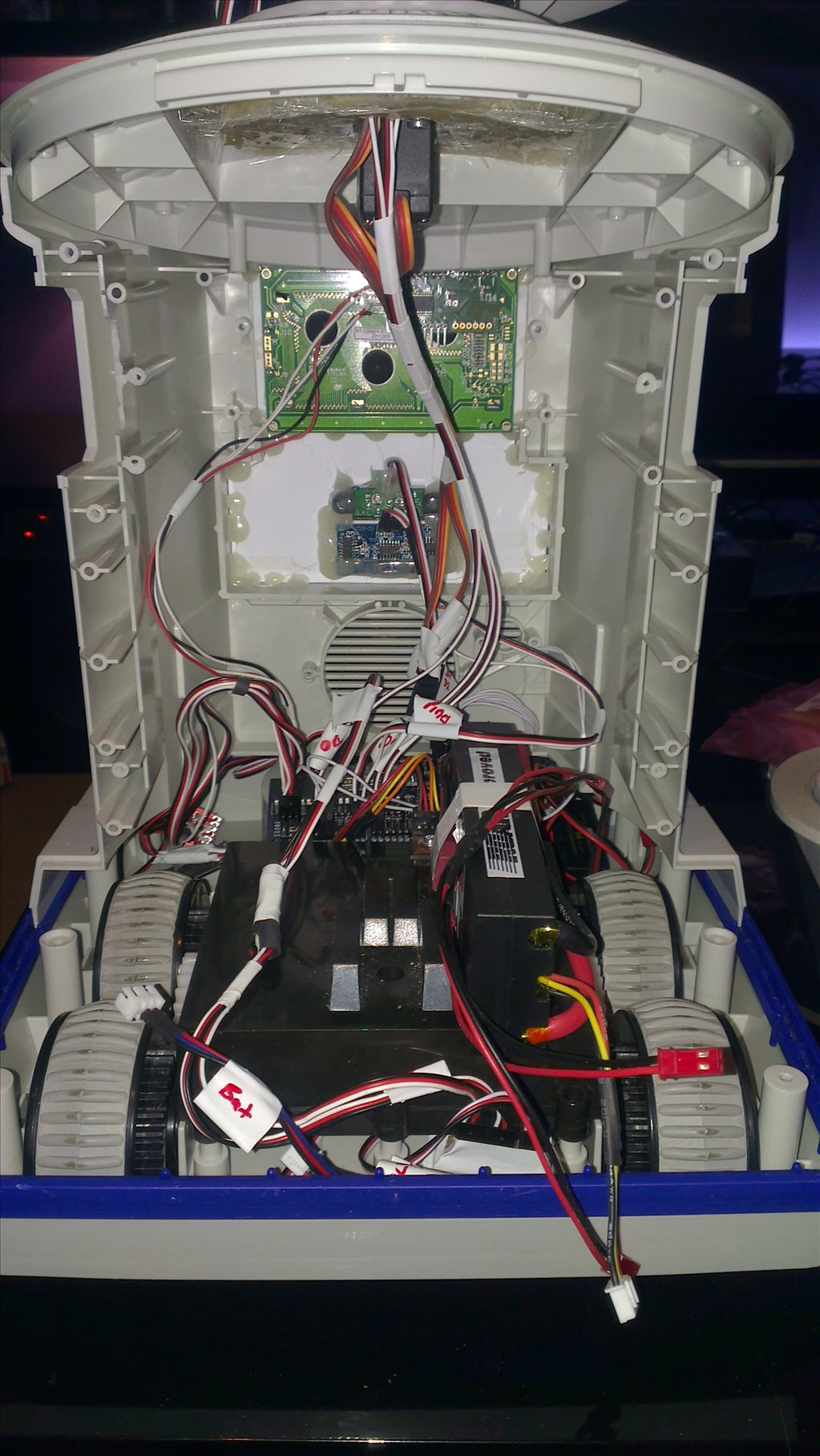
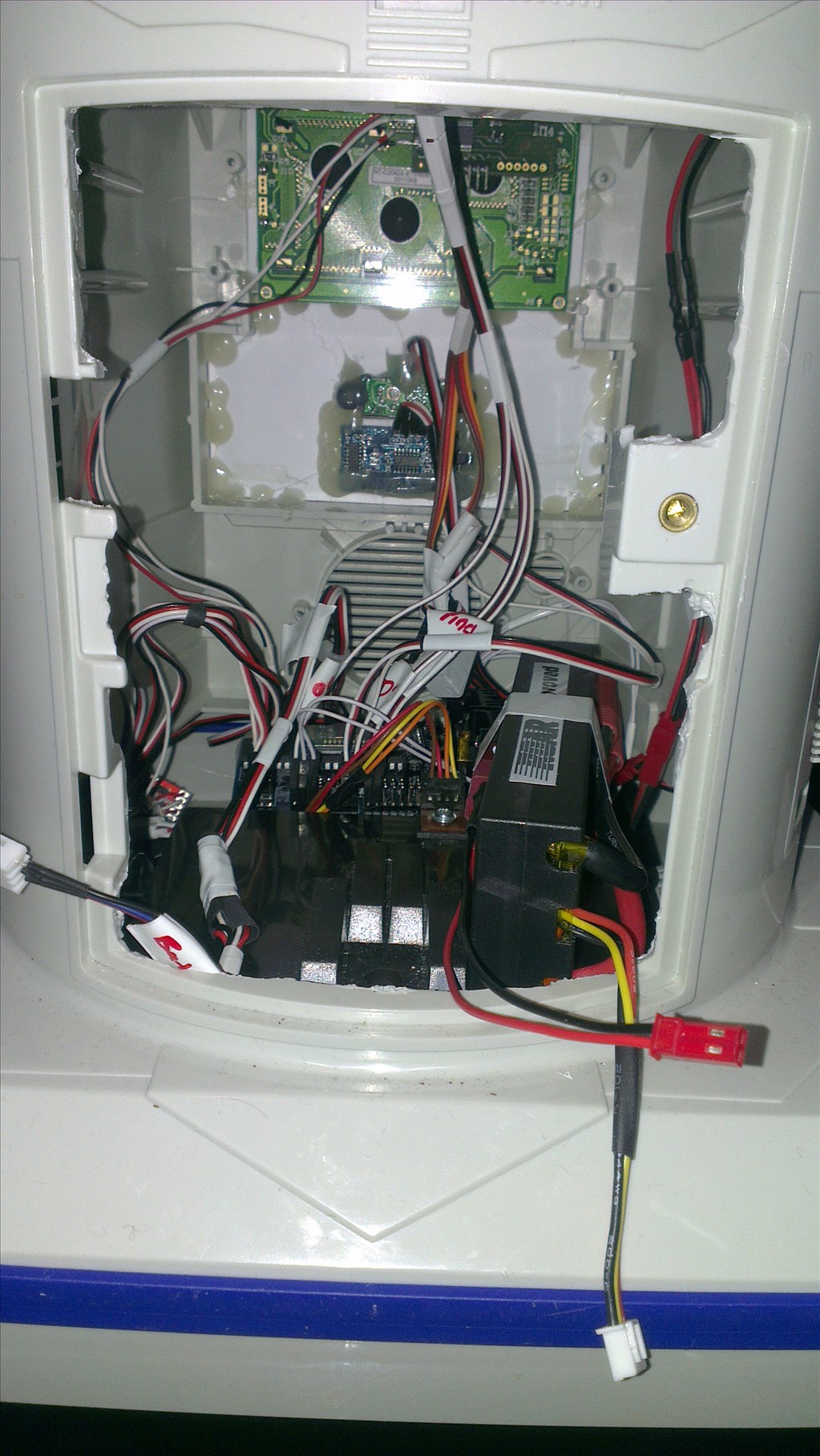
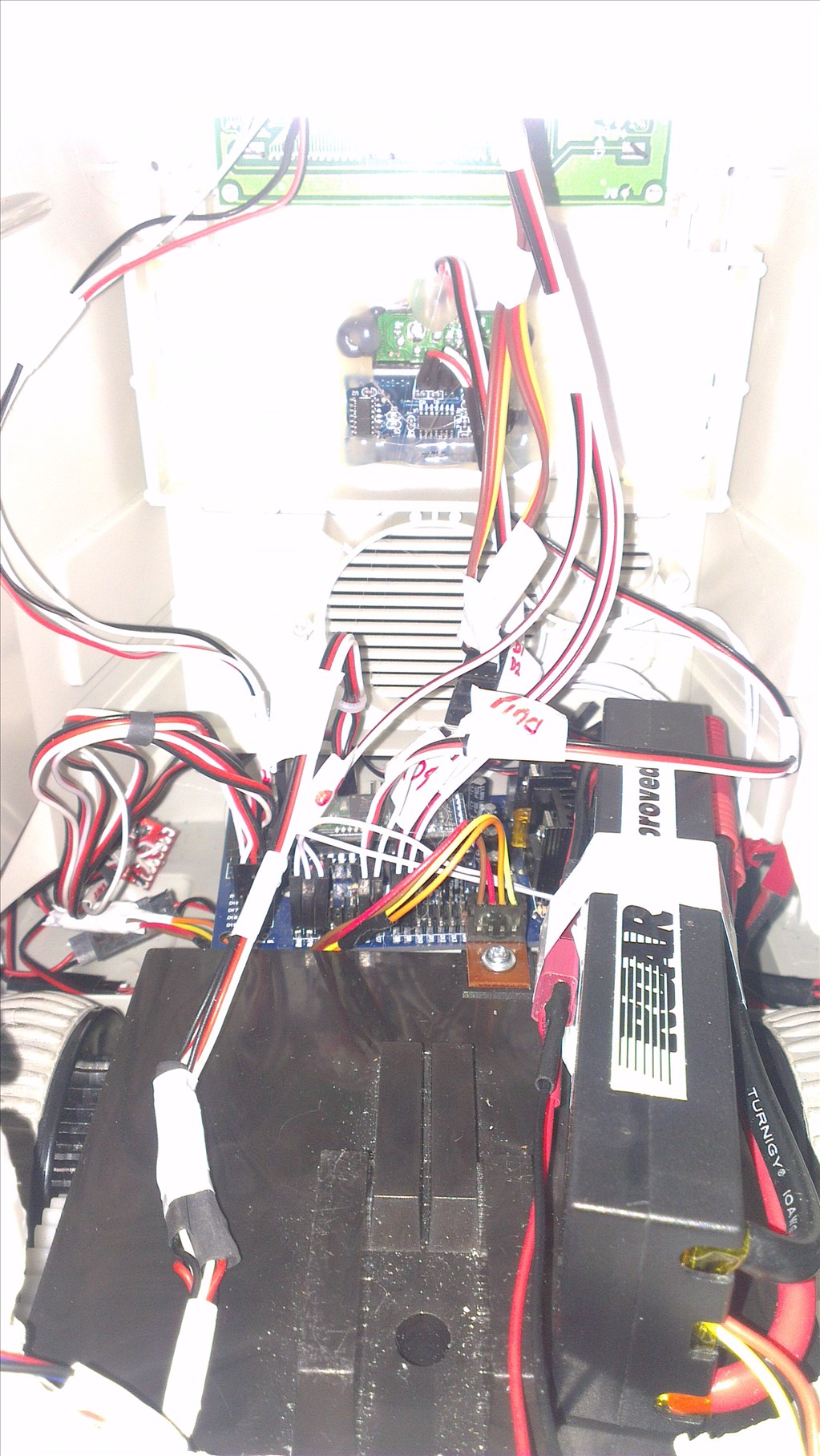
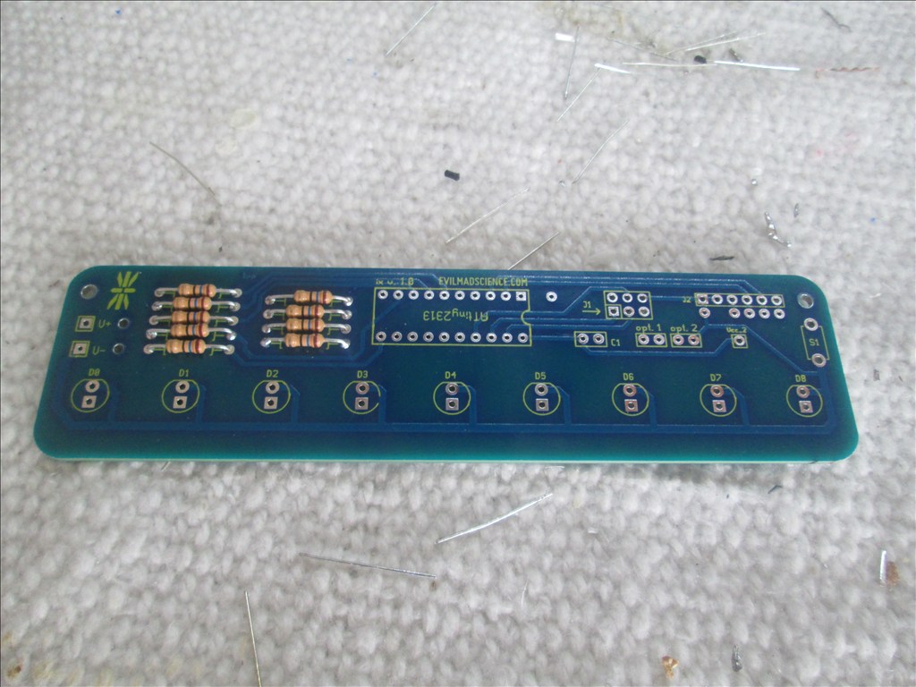
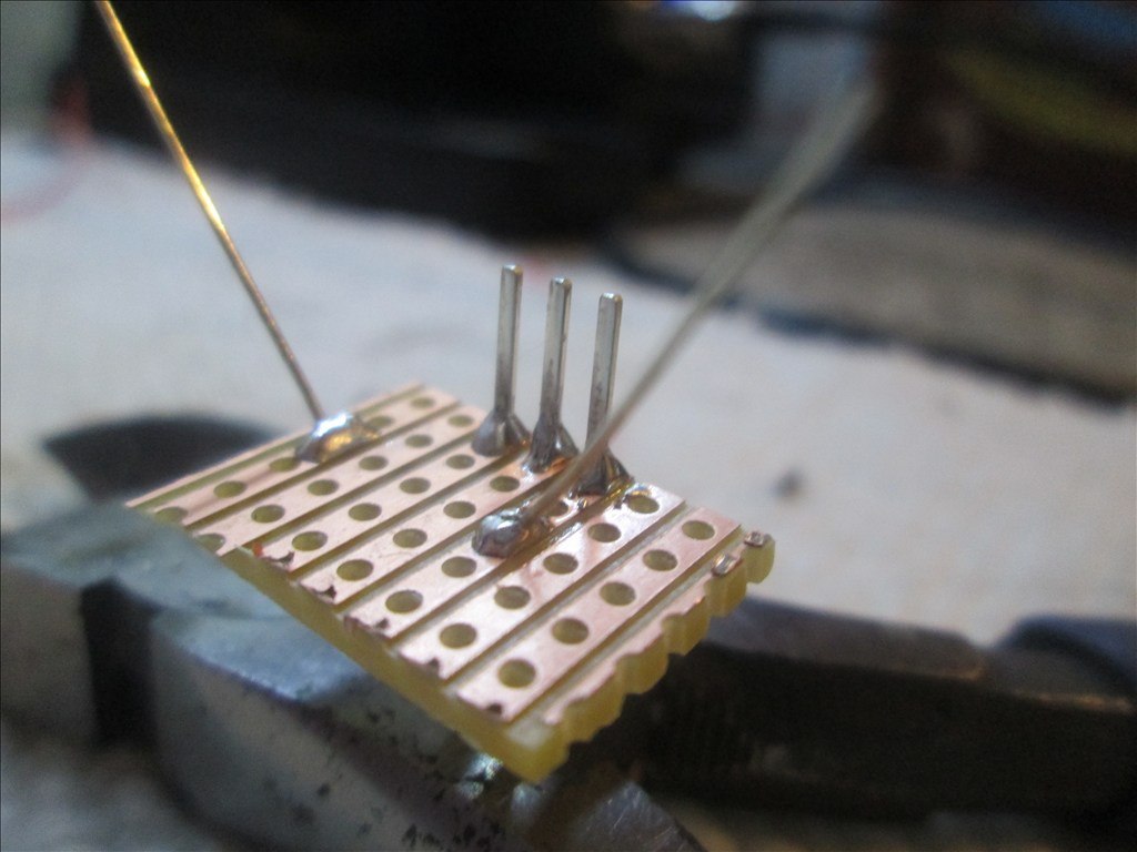
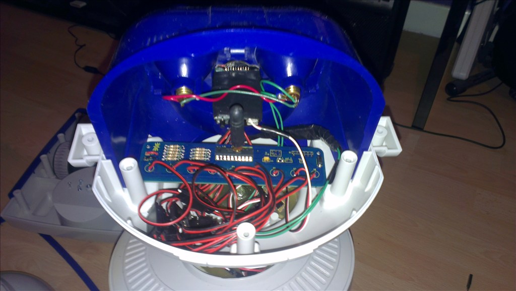
A few more photos as I had the chance to pull them off the camera;
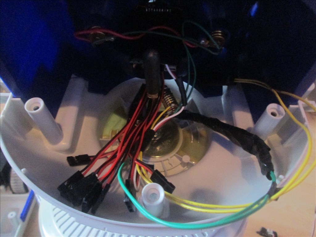
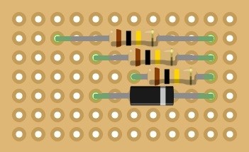
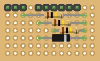
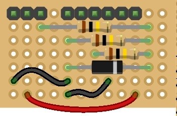
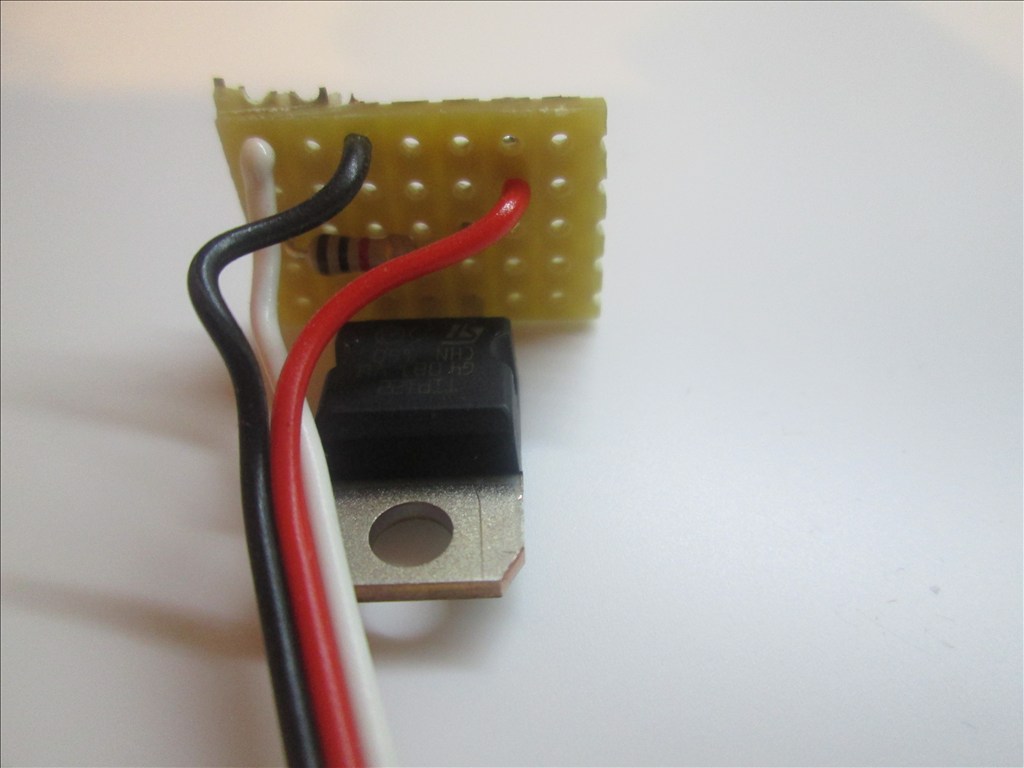
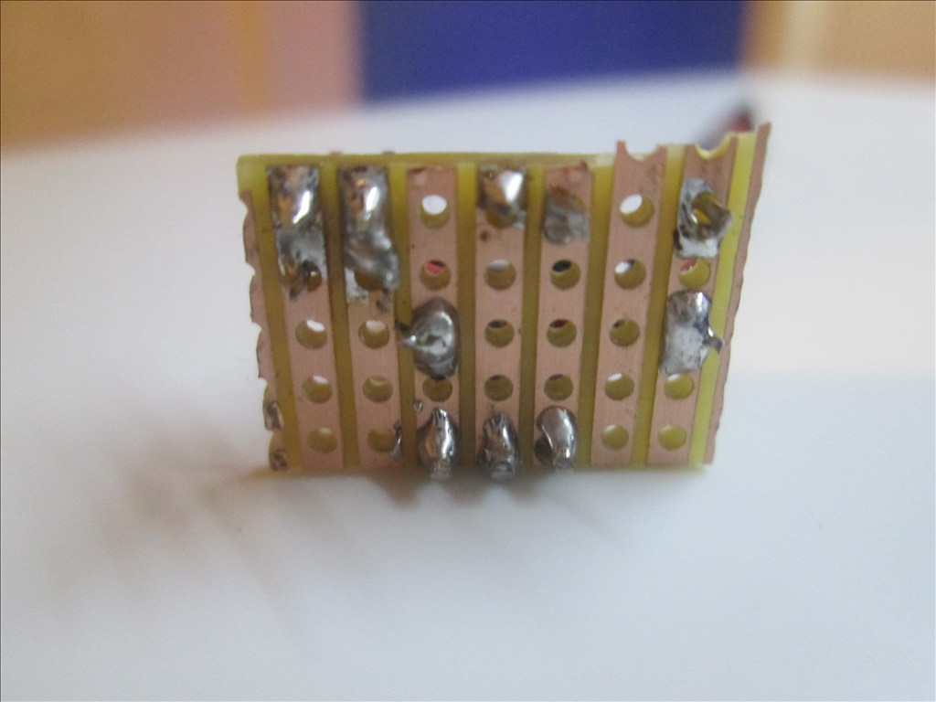
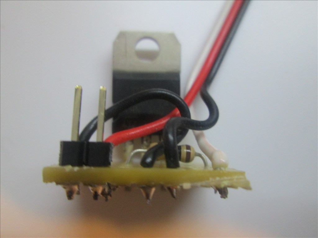
And some photos of one of the TIP circuits. Note, the resistor is covered by the heatshrink but it is on the white wire fixed to the base of the TIP122.
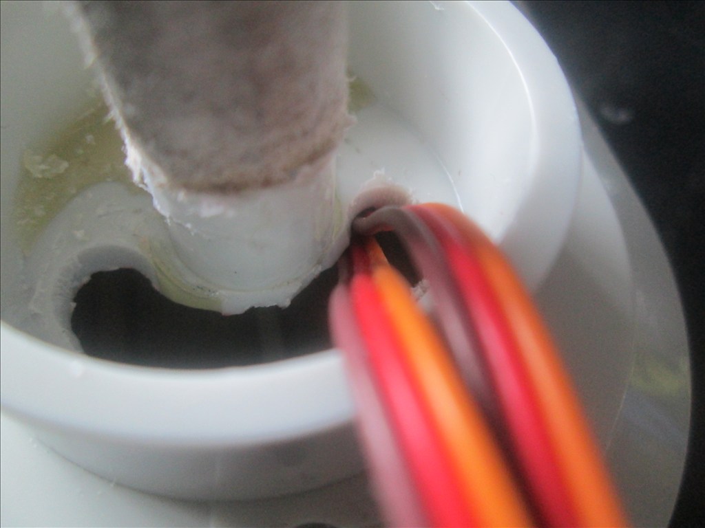
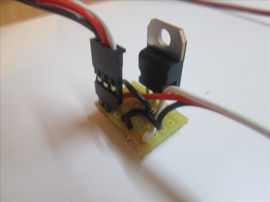
And the end of the extension cable which plugs directly in to the existing wiring of the Omnibot/Hearoid head for the eyes/mouth;
Unfortunately it doesn't lock in to anything so a slight tug and it would come apart. That is something I need to look in to, be it a dab of glue, a piece of tape or soldering that end to the internal wiring.
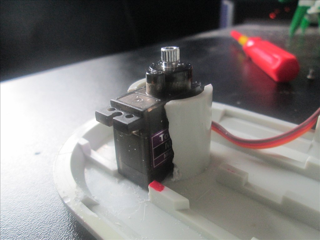
A small update on the arms for the bot. Typically I didn't do any calculations for the servo torque needed to move the elbow/lower arm and the micro servo fitted wasn't man enough for the job so it needed upgrading.
I found the highest torque micro servos I could get which were around the same size, although slightly taller which causes a slight issue but nothing that can't be solved.
I also found I cut the existing mount on the arm where it fits to the torso too short so please excuse the crude card covered fibreglass extension (which is surprisingly strong!).
Anyway, photos...
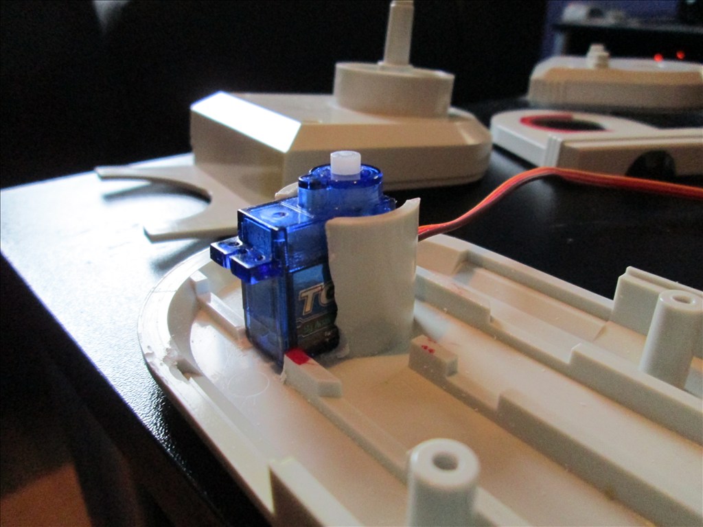
Tower Pro MG90S fitted which will (hopefully) have enough torque to move the arm.
Currently just superglued in position as it'll come out when it get's painted. I'll probably permanently fix it with glue, fibreglass or possibly just milliput it in, dependant on space available.
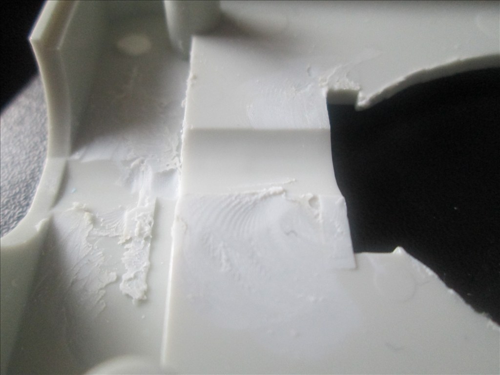
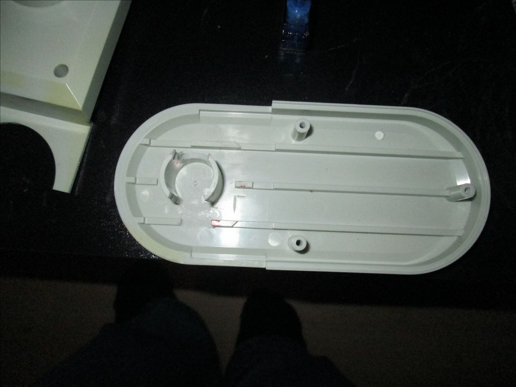
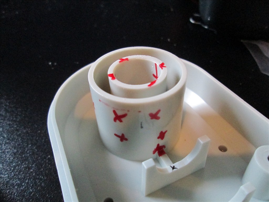
Cleaned up the inside of this piece to allow for a smoother movement.
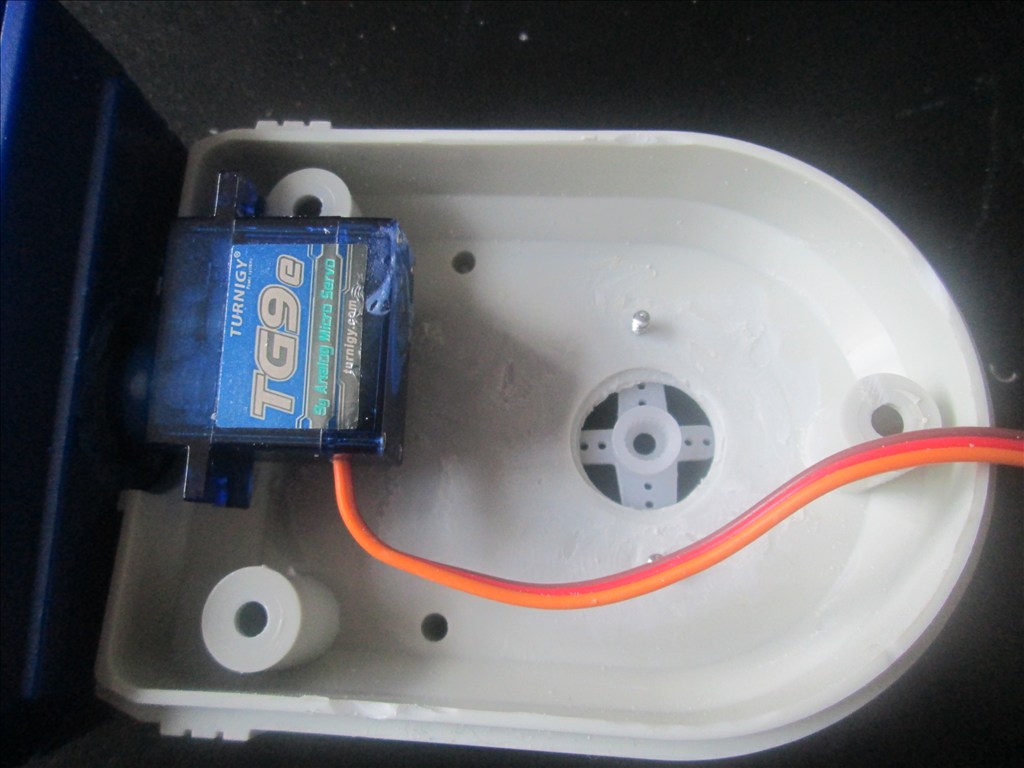
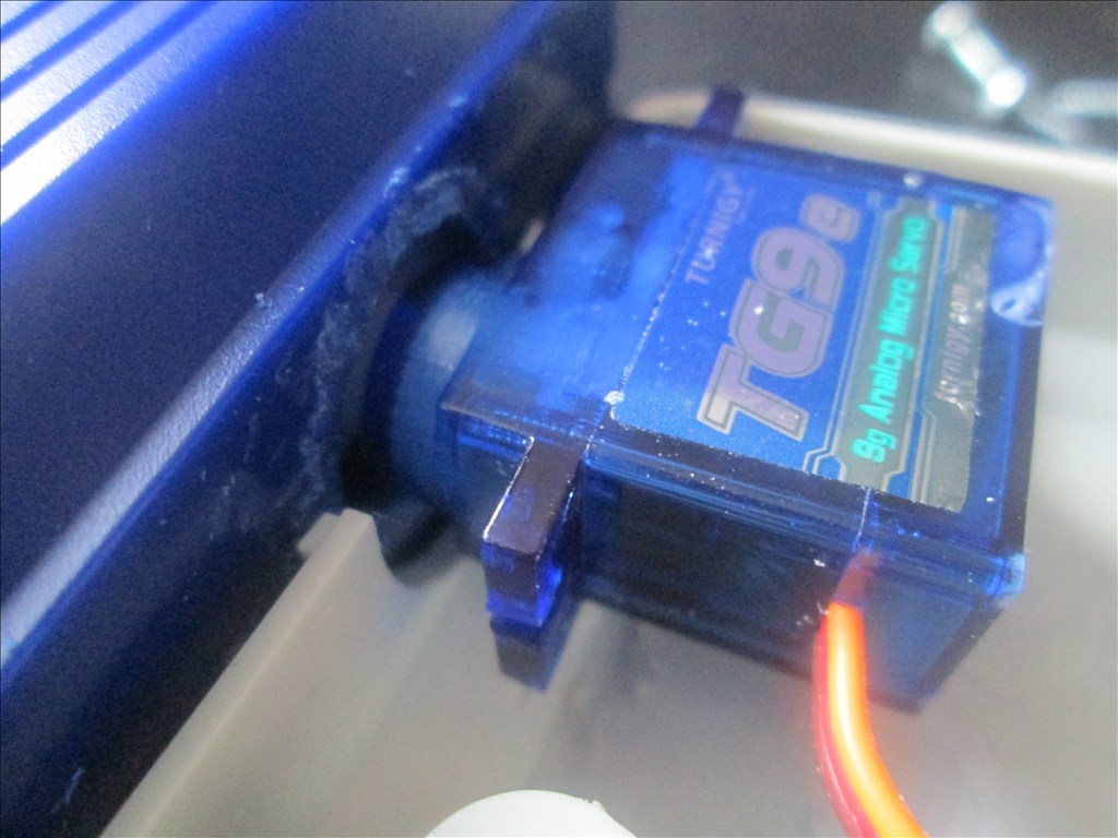
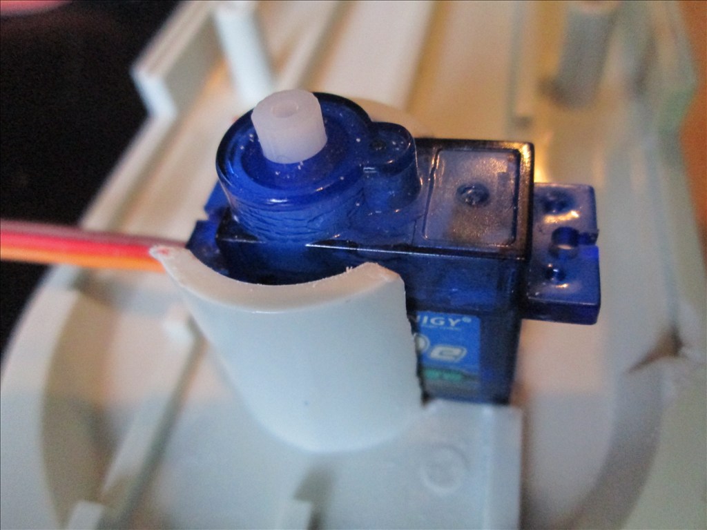
Because the original shaft from the hand clashed with the movement I decided to cut it off and fix it with one of the micro servos originally intended for the elbow. This may not work with the claw hand as the original mechanism goes in to the shaft but I'll cross that bridge when I get to it.
Again, the servo is just super glued in position but will be fitted better once painted.
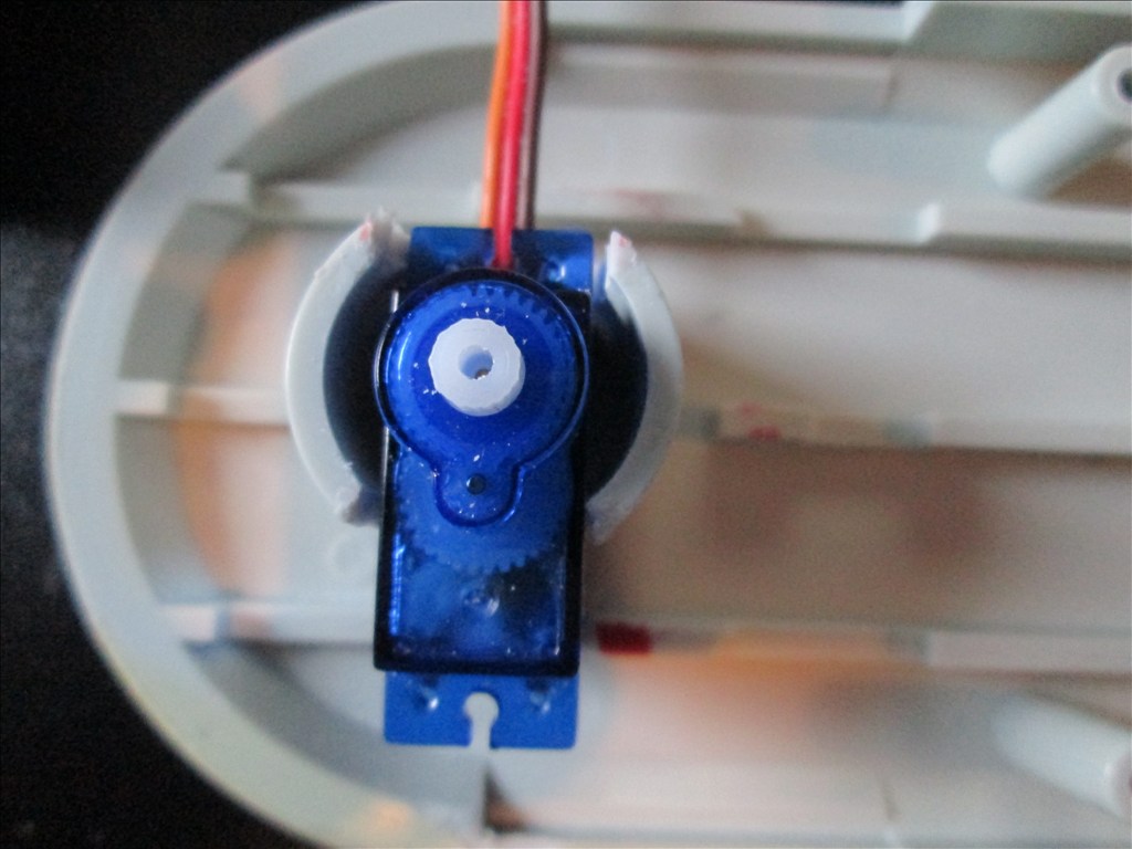
The elbow is mounted to the servo like so. The horn broke but it's not an issue as I need to space the horn away from the plastic by about a mm or two anyway, and then it'll be covered in plastic to form a nice hump that looks like it has always been there.
Inside the hand the servo horn is fitted with hot glue. I know I have said I want to avoid it where possible but I had little choice when trying to get the horn in the exact position. I may trim the hot glue down a bit at some stage and even may replace it all.
The servo cable for the hand rotation pops out here. Enough of a gap is there to avoid any rubbing from the elbow servo.
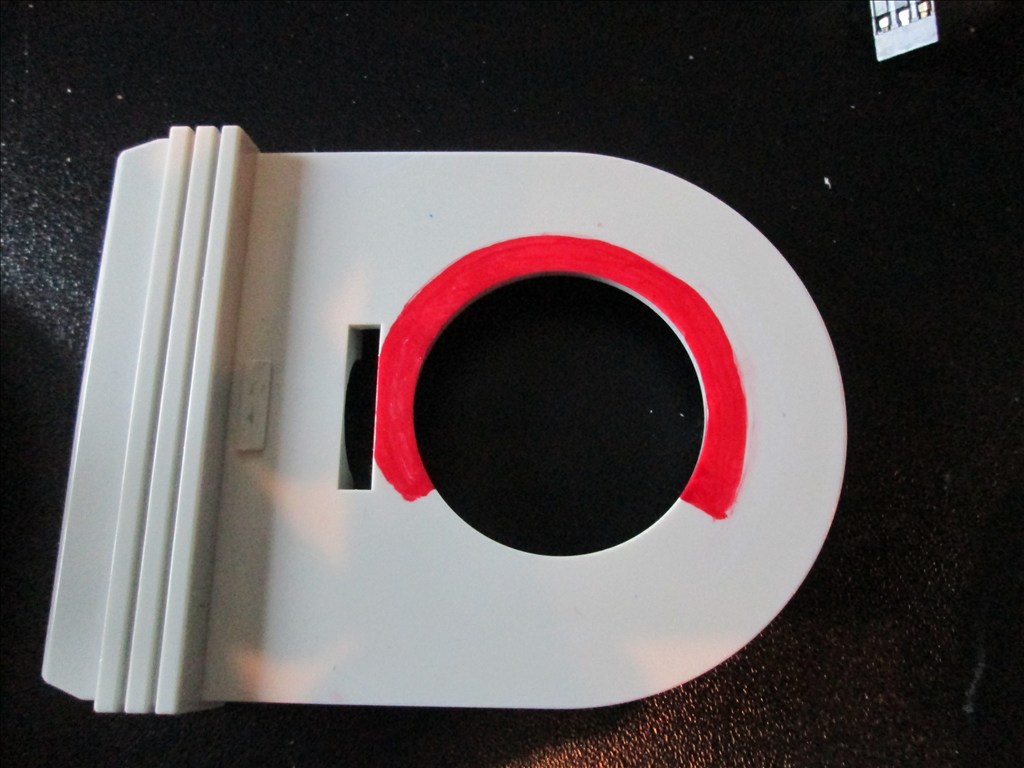
Then a nice slot cut in the shoulder for the hand and elbow servo cables to come through, again with enough space to avoid any rubbing from movement.
The elbow doesn't quite have 180 degree sweep but I didn't want 180 degrees anyway, it's pretty much exactly as I wanted.
I'm yet to test it on the bot but have tested it off the bot and it can just about lift the hand from the elbow servo. The shoulder servo in the torso may need upgrading though as the arm is pretty heavy now, that's the next job but need some milliput and plastic card to build up the inside of the torso a little to support the servo and make it hidden from outside the bot.
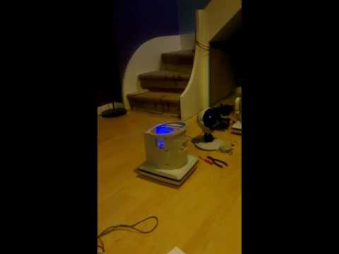
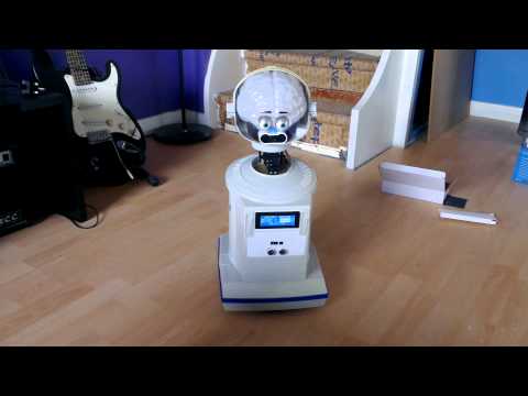
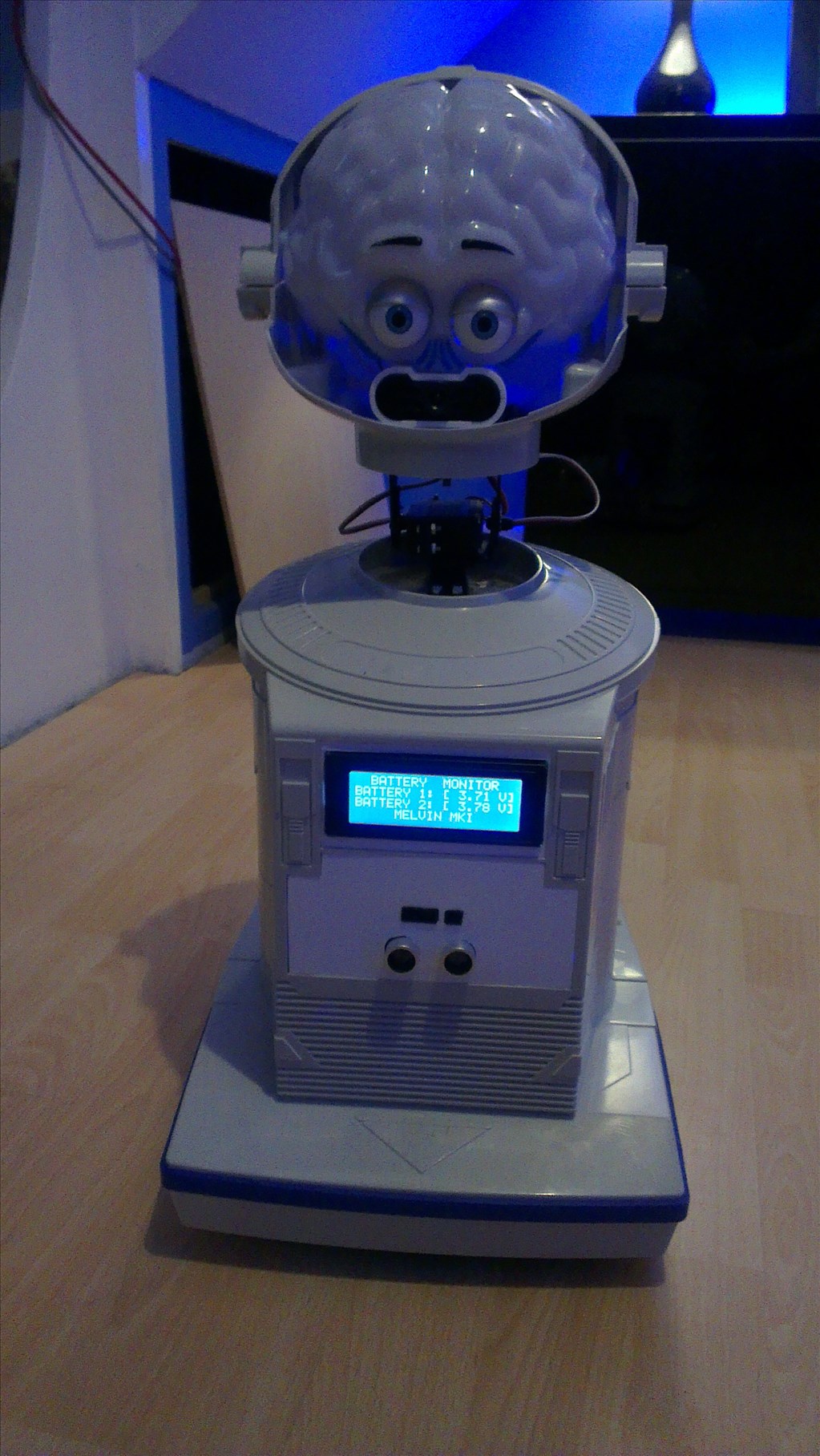
He is getting there now though, and the software side is looking good too with a bunch of scripts written, servos set up, digital ports planned etc.
Another hint on your light switching circuit,you should add a cap,so the light slowly comes on the light will last longer and no burn-outs
It's not my circuit, it's the one that's been floating around the forum for a while. I did think about adding a cap for smoothing out the voltage (didn't realise it would bring it on slow - by slow how slow?) and a diode (which is sometimes shown) but for the sake of this build, and because I don't have any, I decided against it.
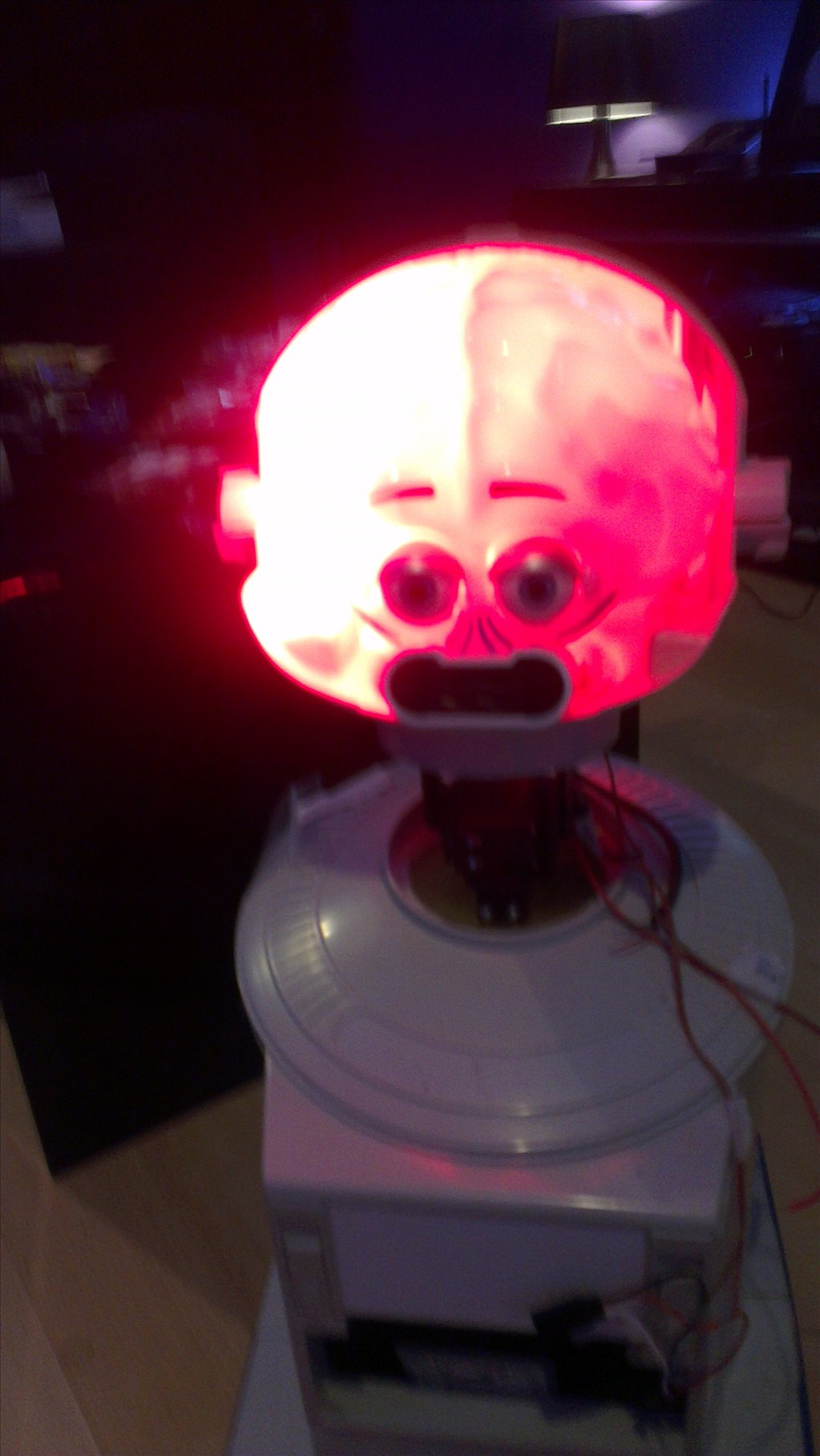
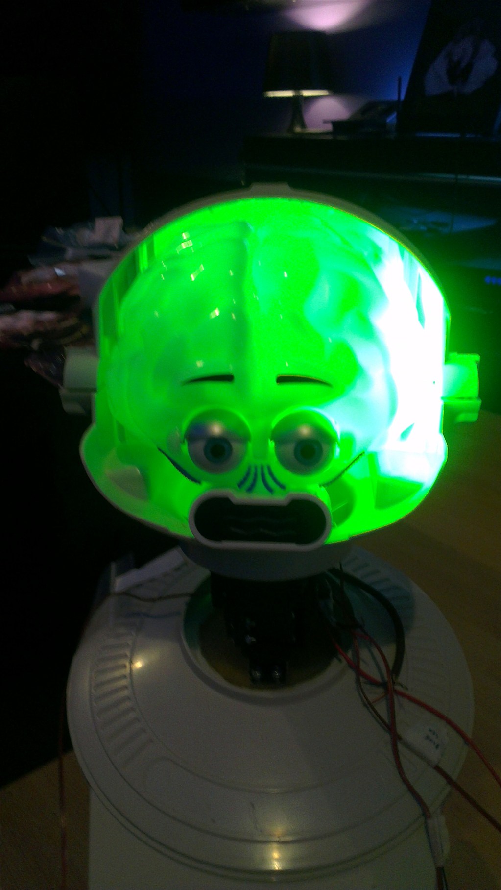
The head is complete now too, I decided against two switches for the eyes as I am getting low on available digital ports. I only have 3 spare and that's without the MP3 board which I may put in there.