


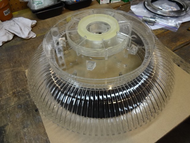
-635353562186322812.png)


Hi all,
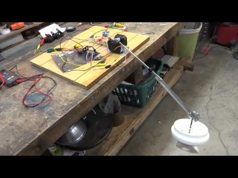
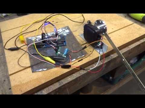
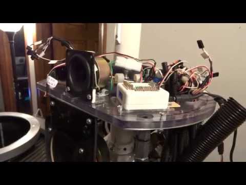
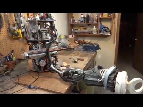
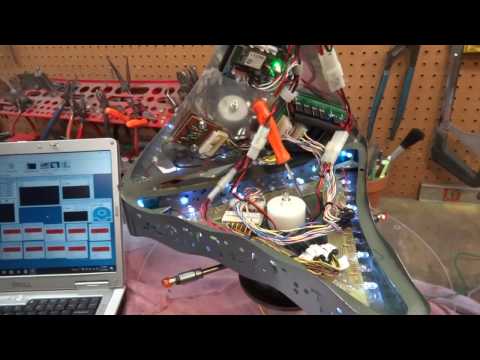
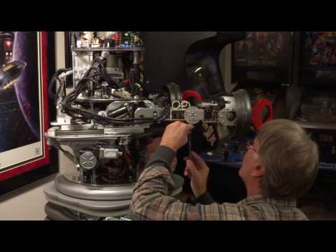
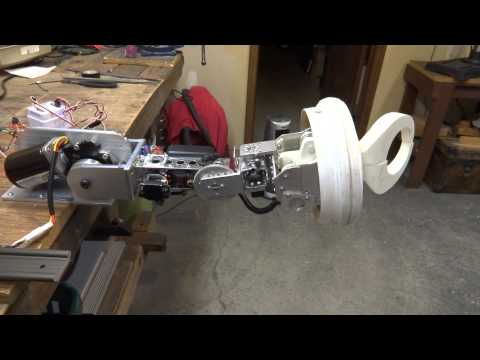
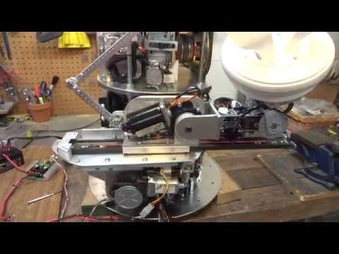
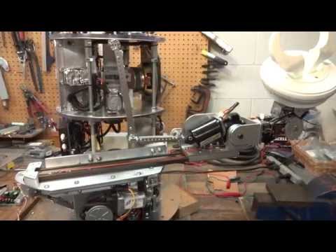
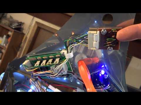
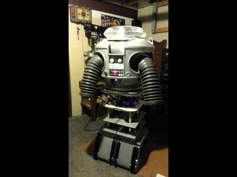
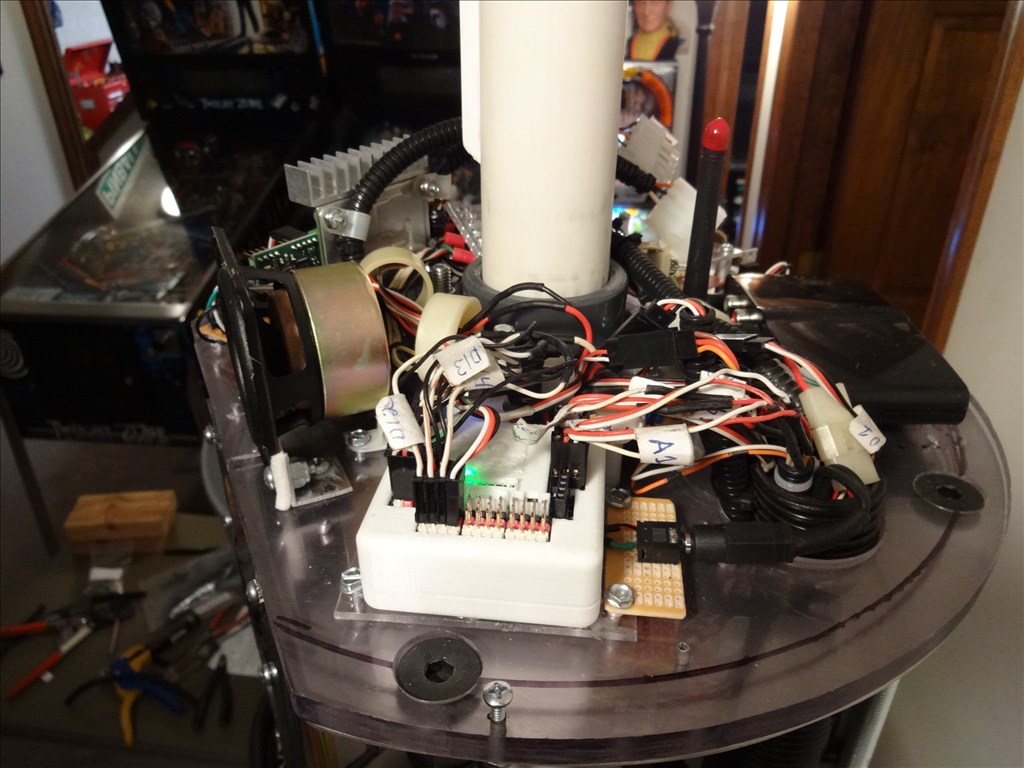
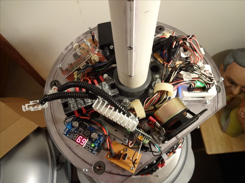
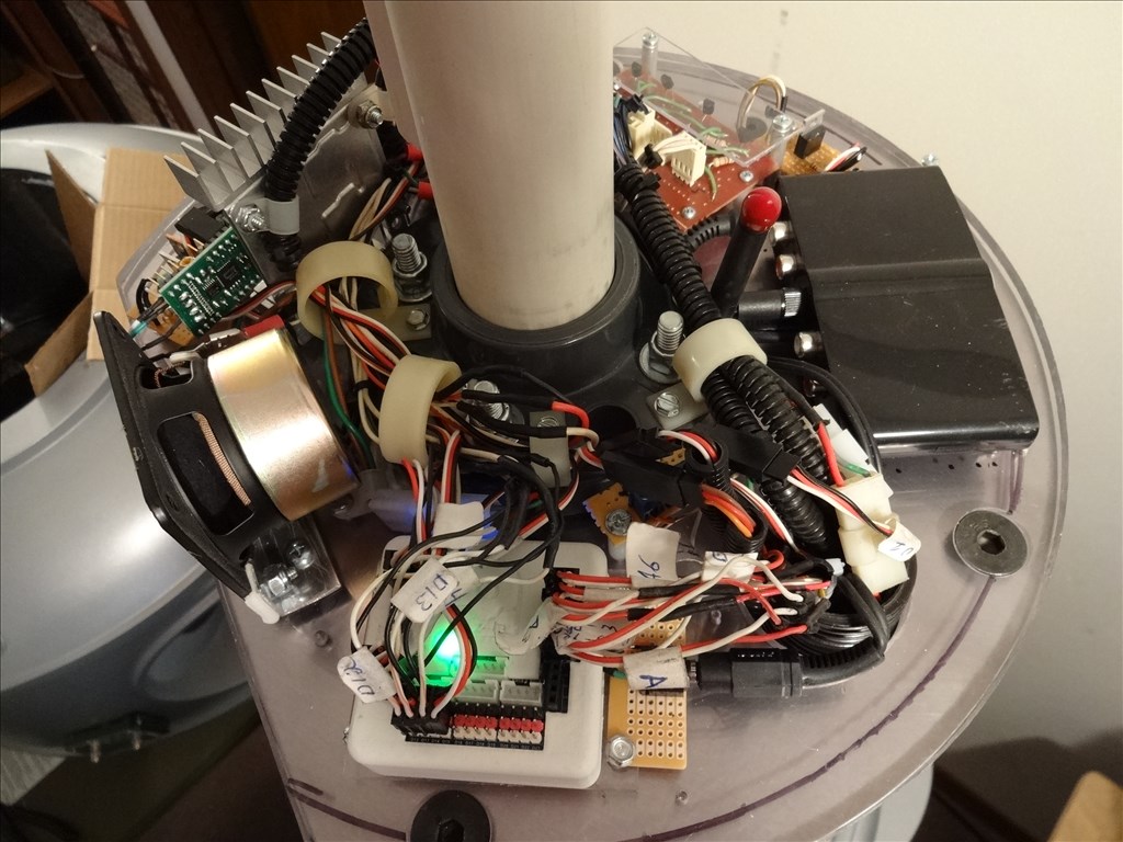
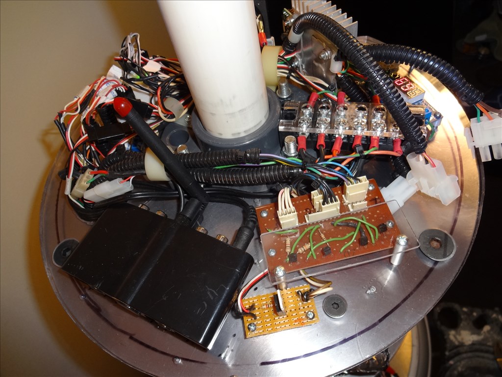
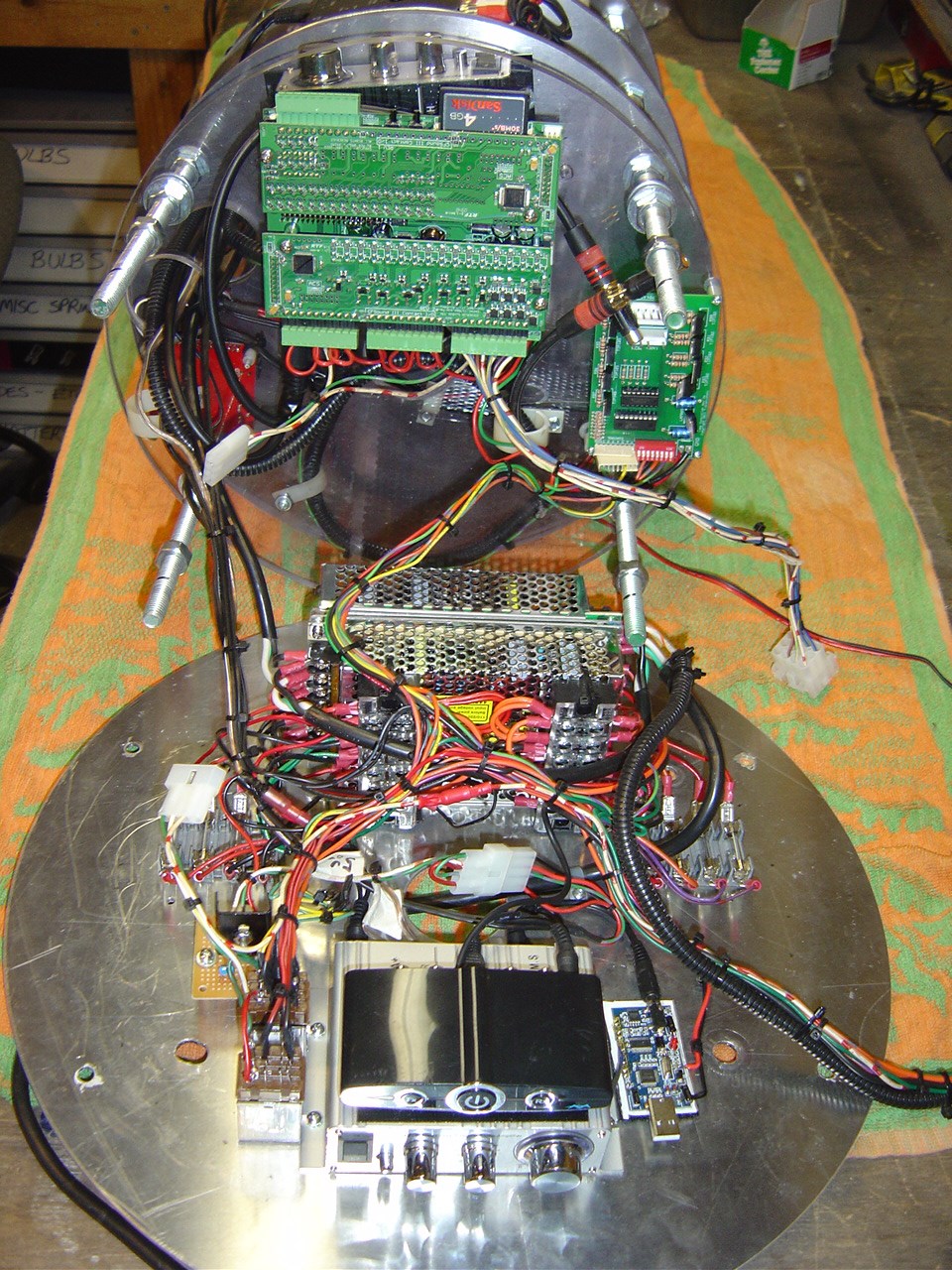
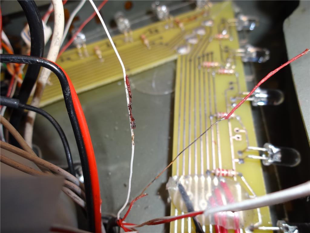
I'd like to share a video I just took of my full size Lost in Space B9 robot that's controlled by two EZ-B controller boards. Right now they are controlling limited movement and voice response of a few motors, lights and sound files played from a Sparkfun MP3 Trigger board. Although I'm just starting with the animation and have more building on the actual robot the result (mostly thanks to the EZ Robot controller board) is shocking. Please have a look at this (4 minute) You Tube vid and enjoy.
Please excuse some Technical camera lighting and sound issues. This is the first time I'd made and posted a vid online.
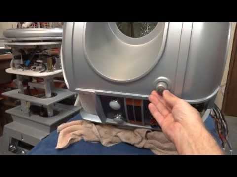
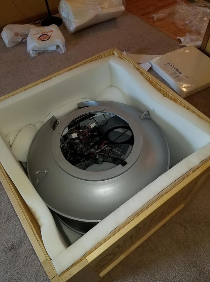
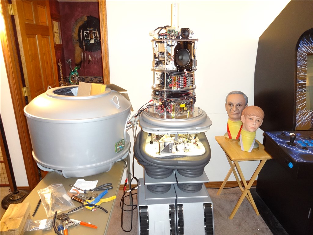
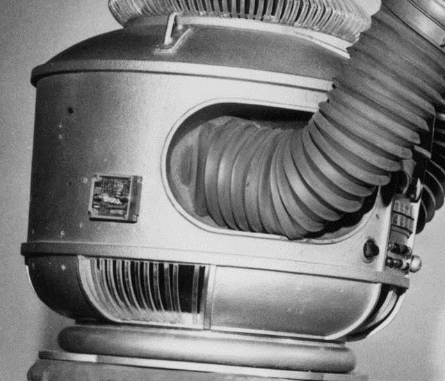
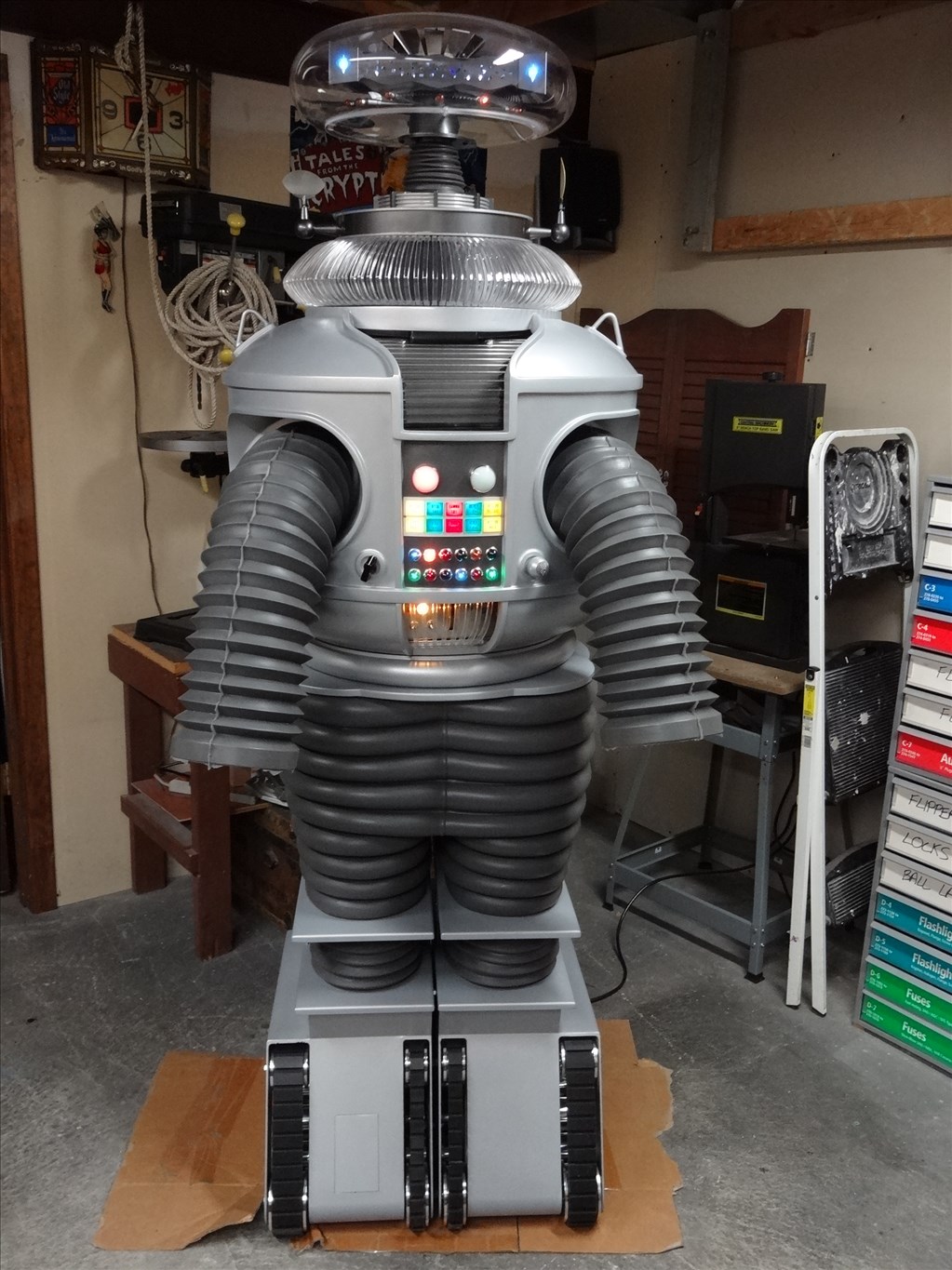
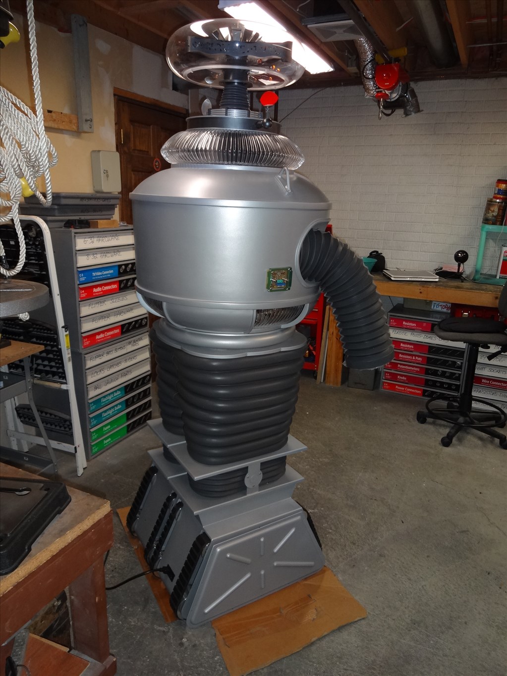
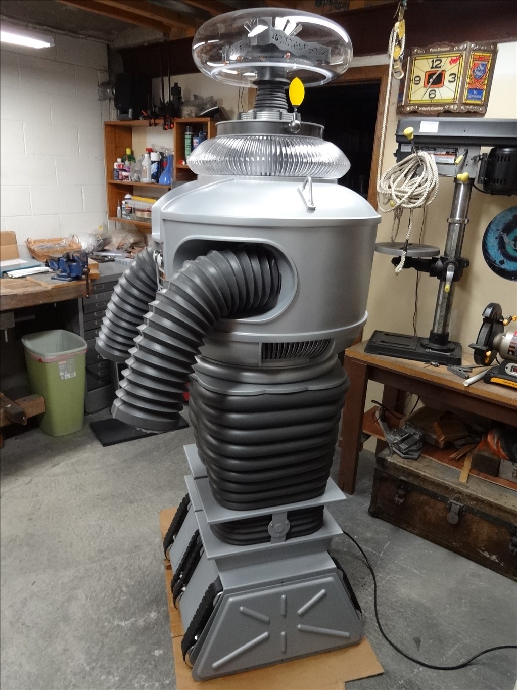
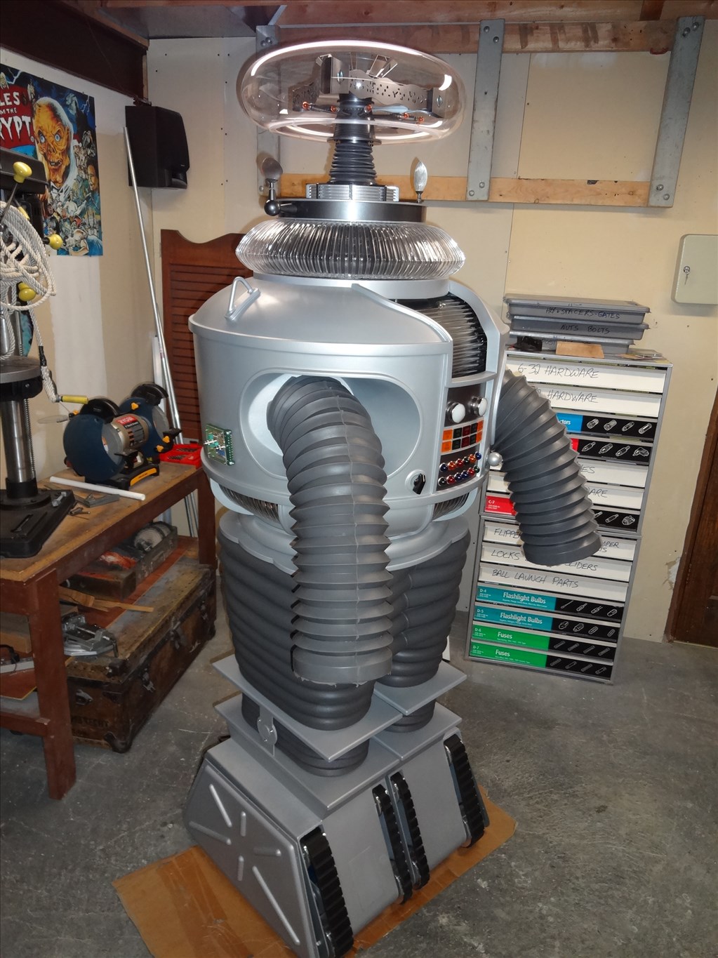
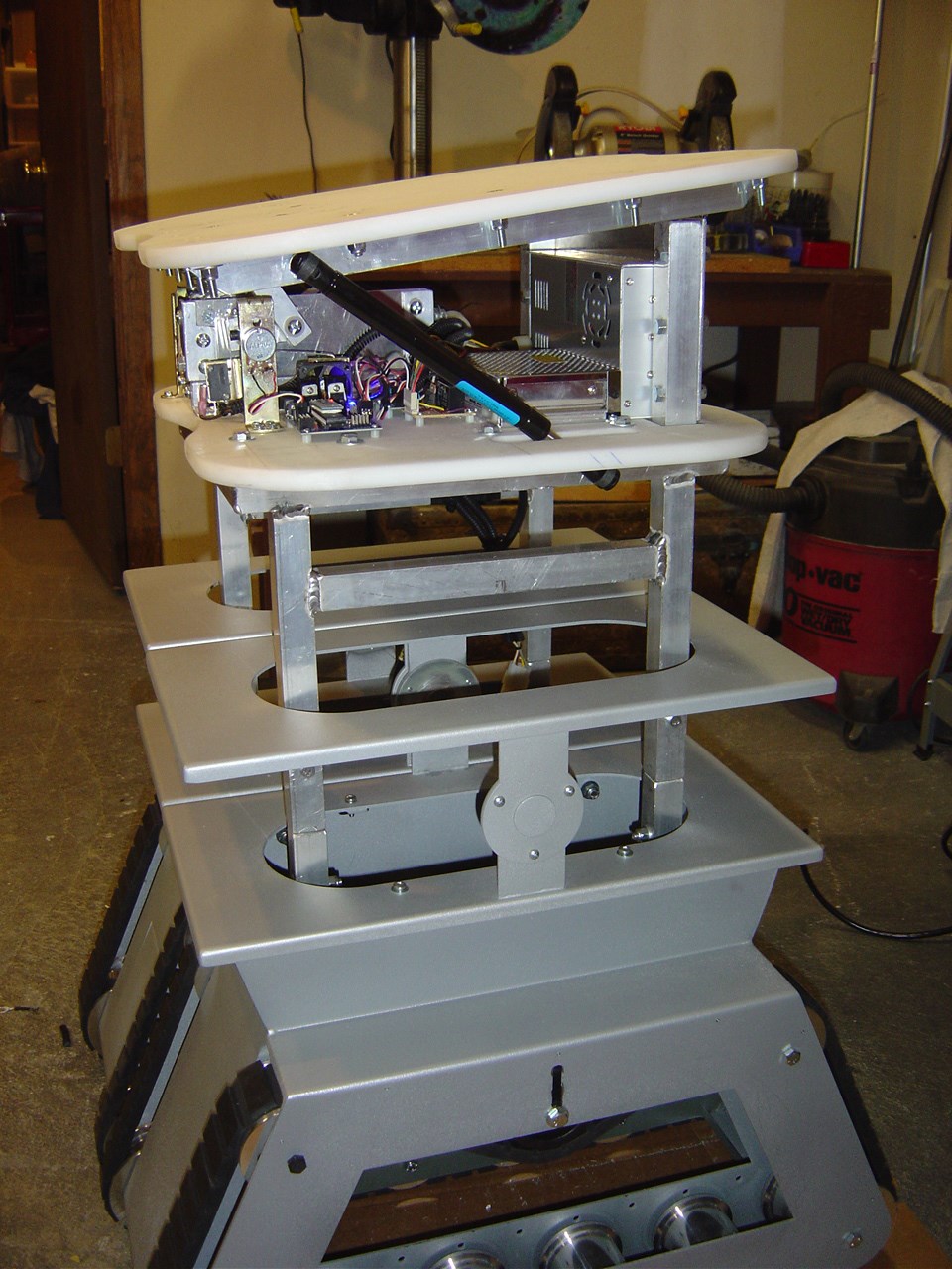
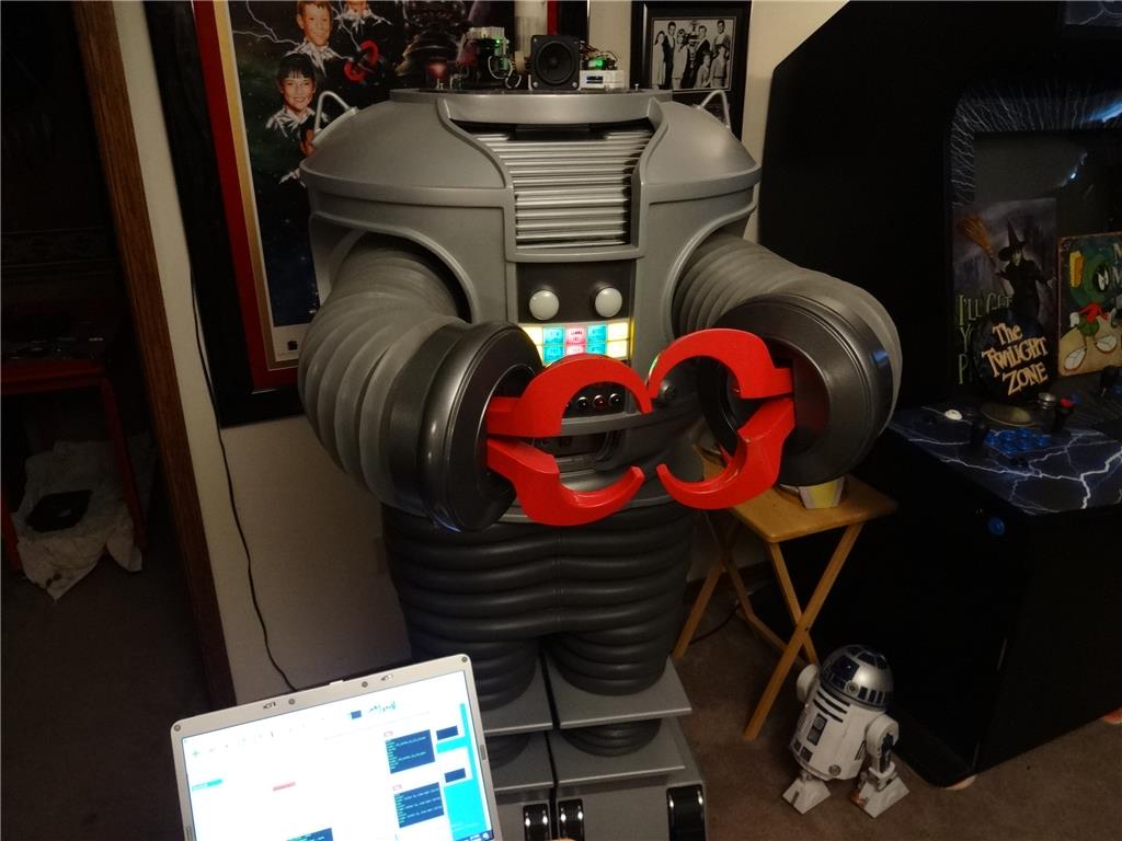
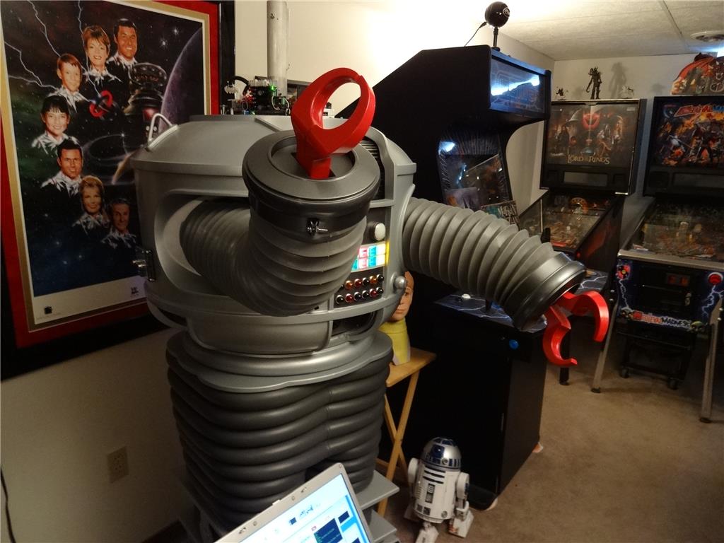
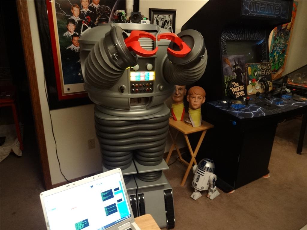
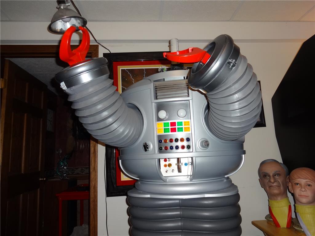
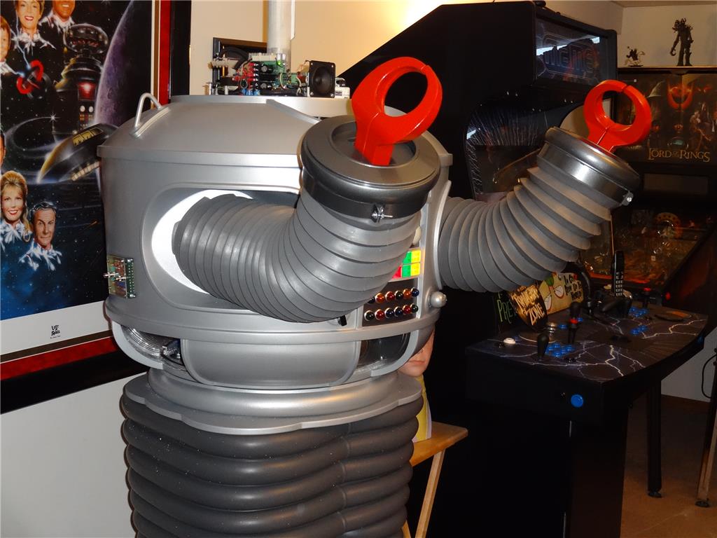
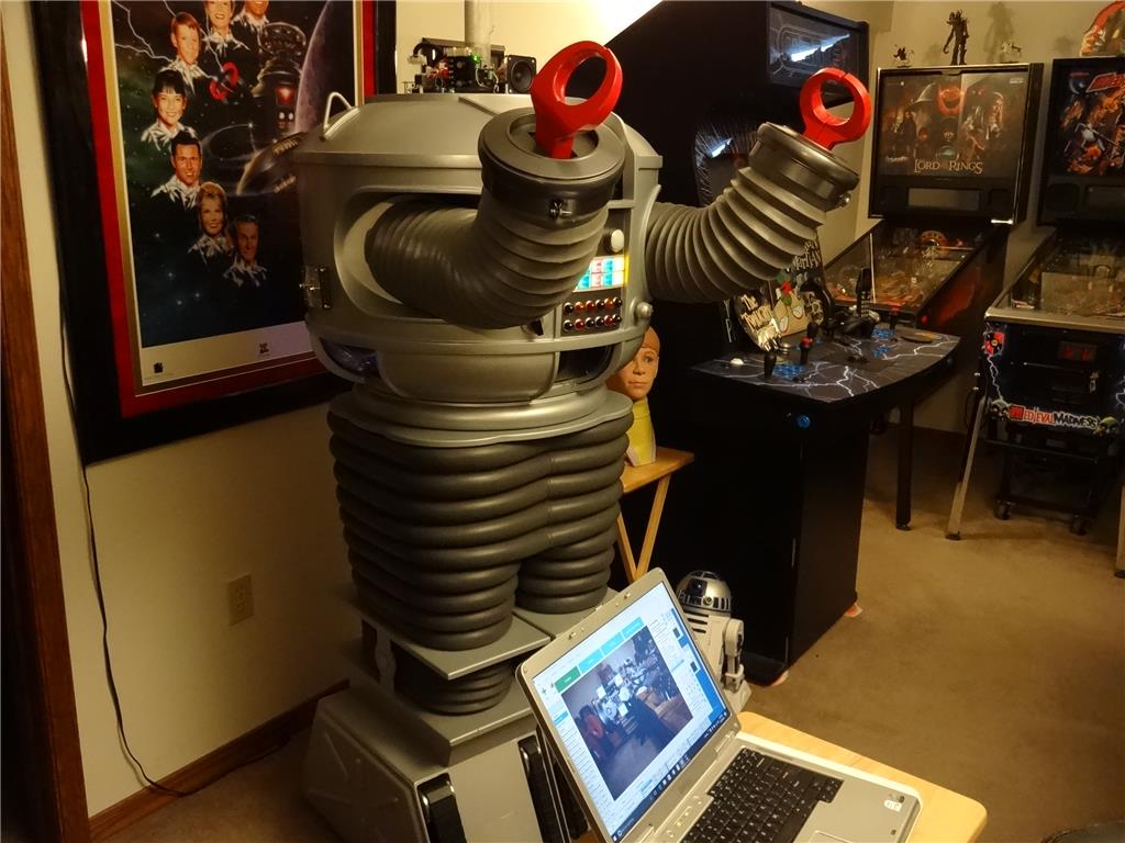
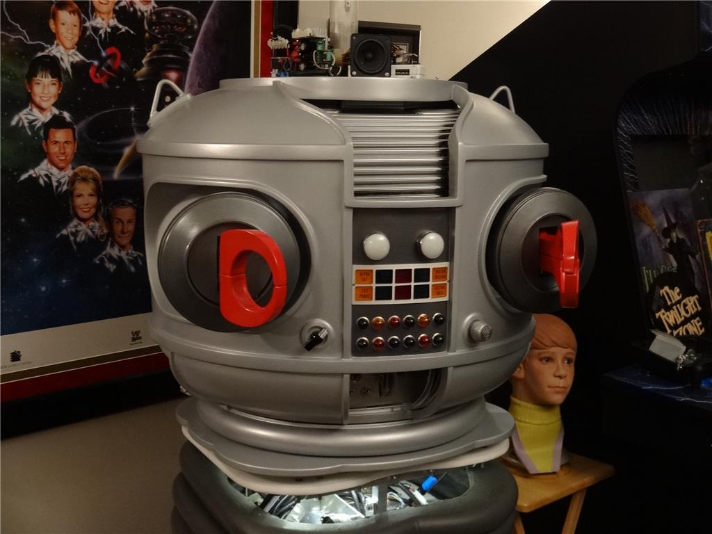
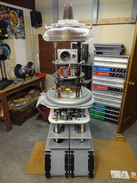
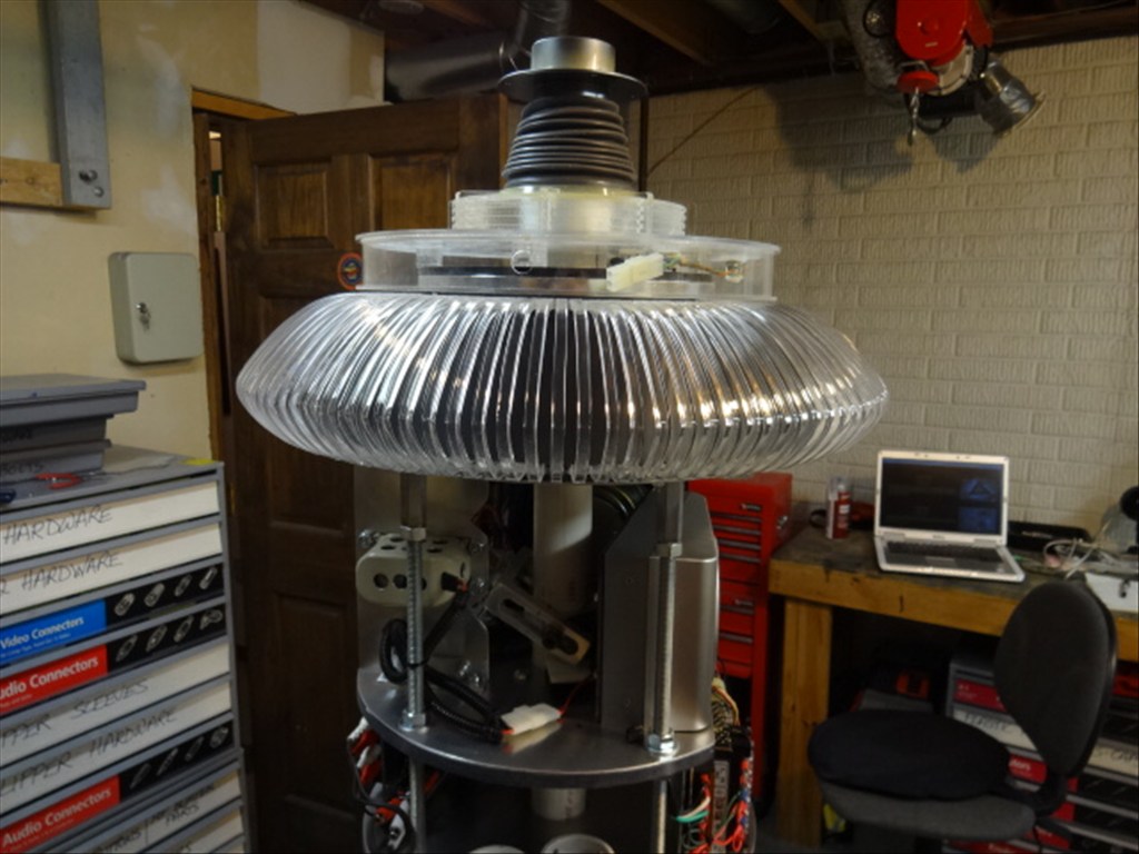
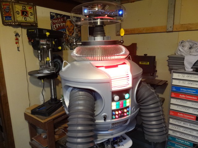
EDIT 8/2/13: Just realized I have no good pictures of how my B9 will look when complete. Here's one of the actual TV robots from the 60's TZ show Lost in Space and one recent shot of where I'm at with my build over 1 1/2 year after I started. Enjoy:


Thanks, Dave Schulpius
Discover more robots

Ericez's Rori The Coffee Robot For Movie
Robot56's Just Another Omnibot

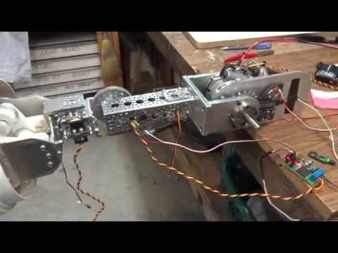
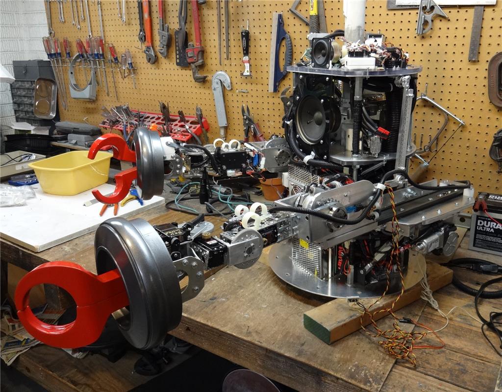
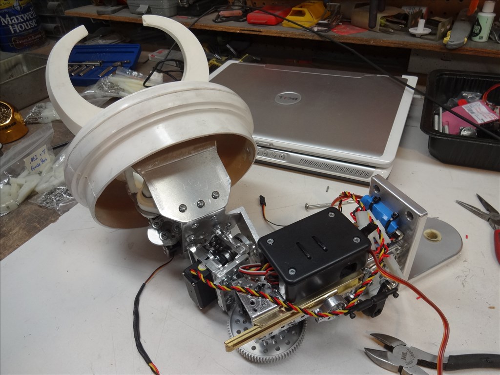
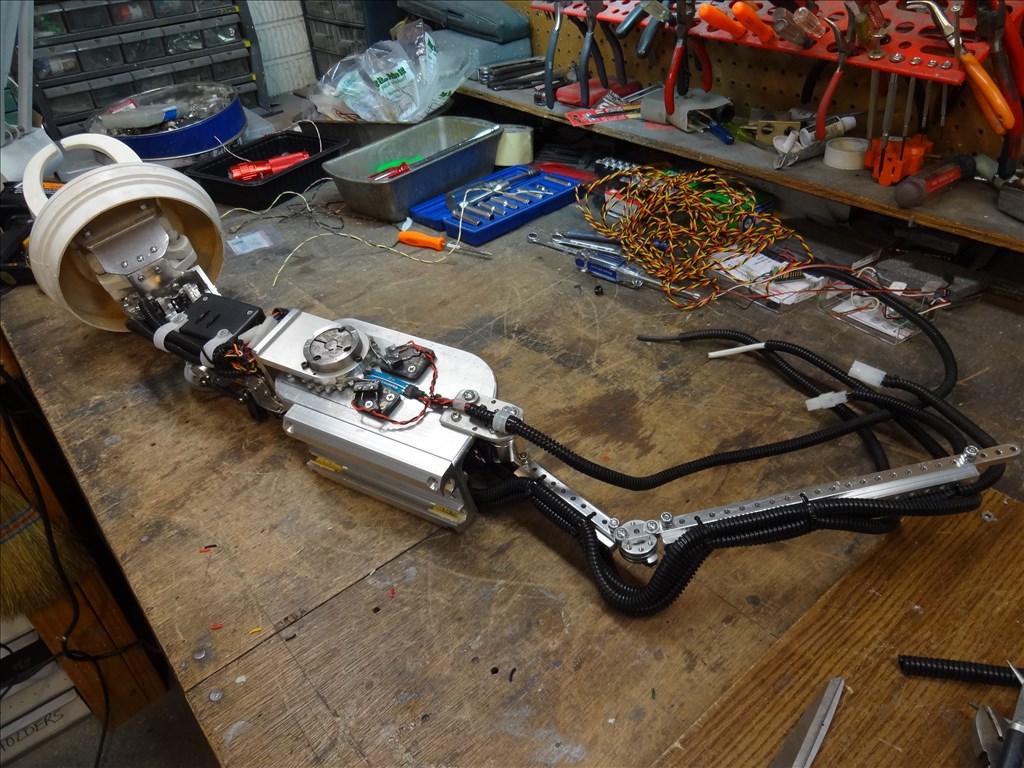
I have some pictures of my prototype for the arms. It is still in a very rough stage, but you may be able to get some ideas from it.
Let me first start by explaining this. My brother and I are working on this together. He currently is a trash collector. I drive for a company that hauls hazardous waste. Until recently, when work was scarce we would often haul tractor trailer loads of demolition from transfer stations to the landfill. We both keep our eyes open for anything that can be salvaged for the robot. My cellar if full of auto parts, small appliances, discarded street signs, sheet metal, too many cordless drills to count, etc.
I say this because my design is partly based on using parts that I have on hand. I kind of look through the piles of junk and figure out how to incorporate them together into something that might work.
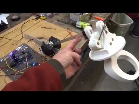
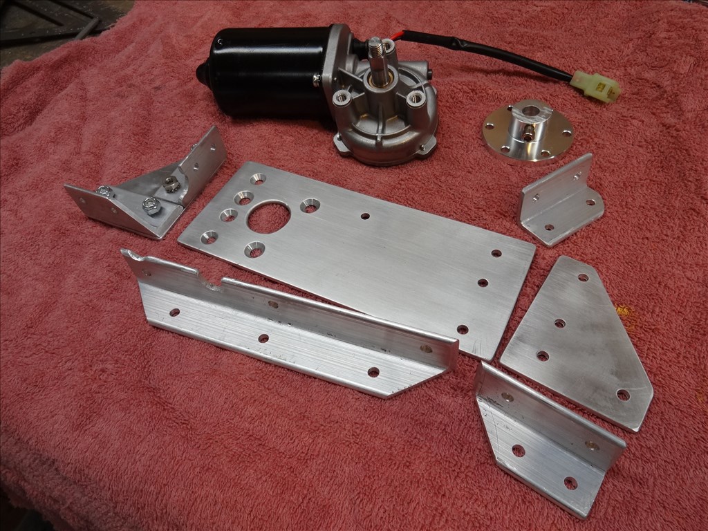
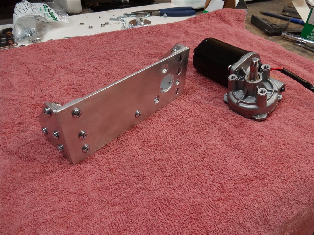
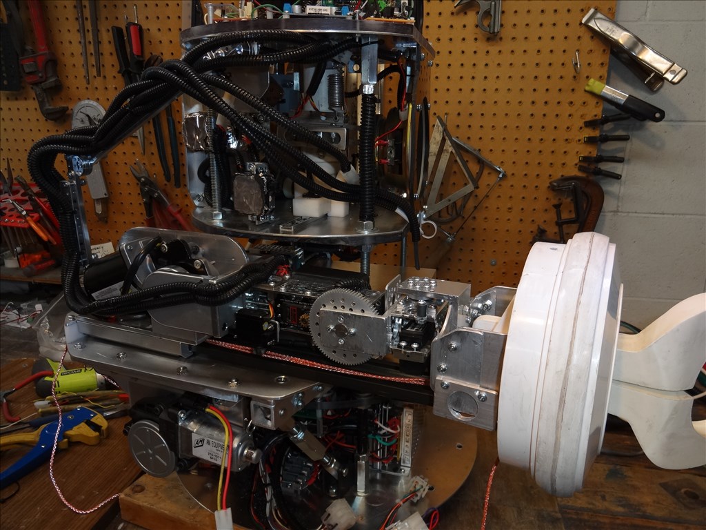
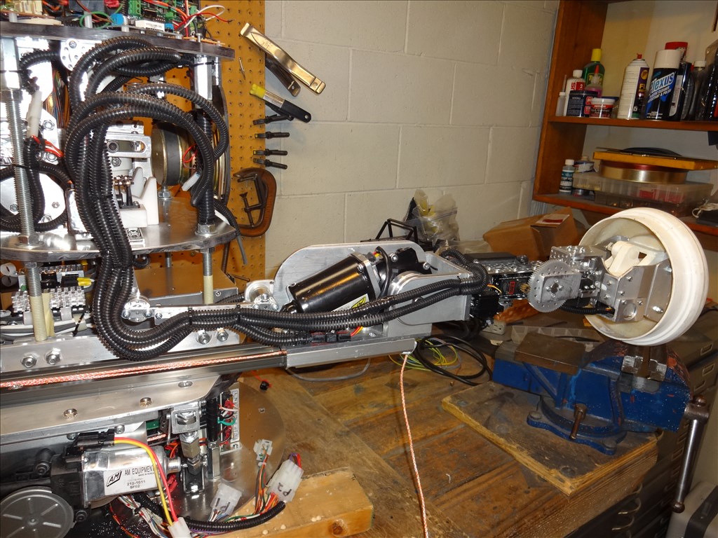
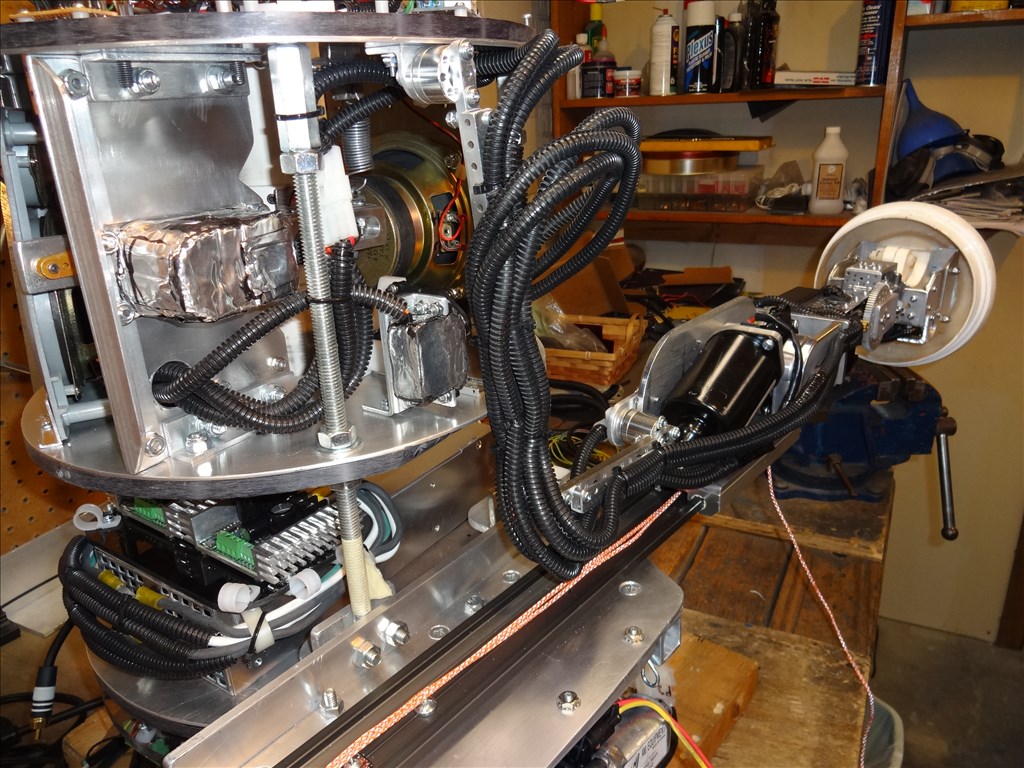
The arm will consist of a "shoulder plate" that will be on a sliding mechanism in the torso to slide back and forth. Currently it is made of MDF. I will replace it with 1/4" aluminum when I get the bugs worked out. When it is all the way forward it will be flat against the back of the arm socket. The motors to move the elbow joint are mounted on this plate. They kind of fit around the arm sockets inside of the torso. The scribbled sharpie lines that you see on the front are where I traced around the inside of the arm socket. The elbow joint is just far enough out to clear the socket.
The idea is to keep the weight of the motors inside the robot. I am not sure if this will work for you Dave. You already have a lot of space taken up inside your torso. I am going to get the arms in first, and then work everything around them. You may be able to make it streamline enough to fit.
To move the plate, I have a pair of automotive electric window tracks. I will mount them with the motors low and in the back of the torso to offset the weight of the arms. I am not sure if I will use drawer slides, or just put holes on the plate and have it slide on rods of some sort.
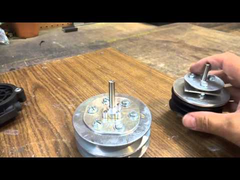
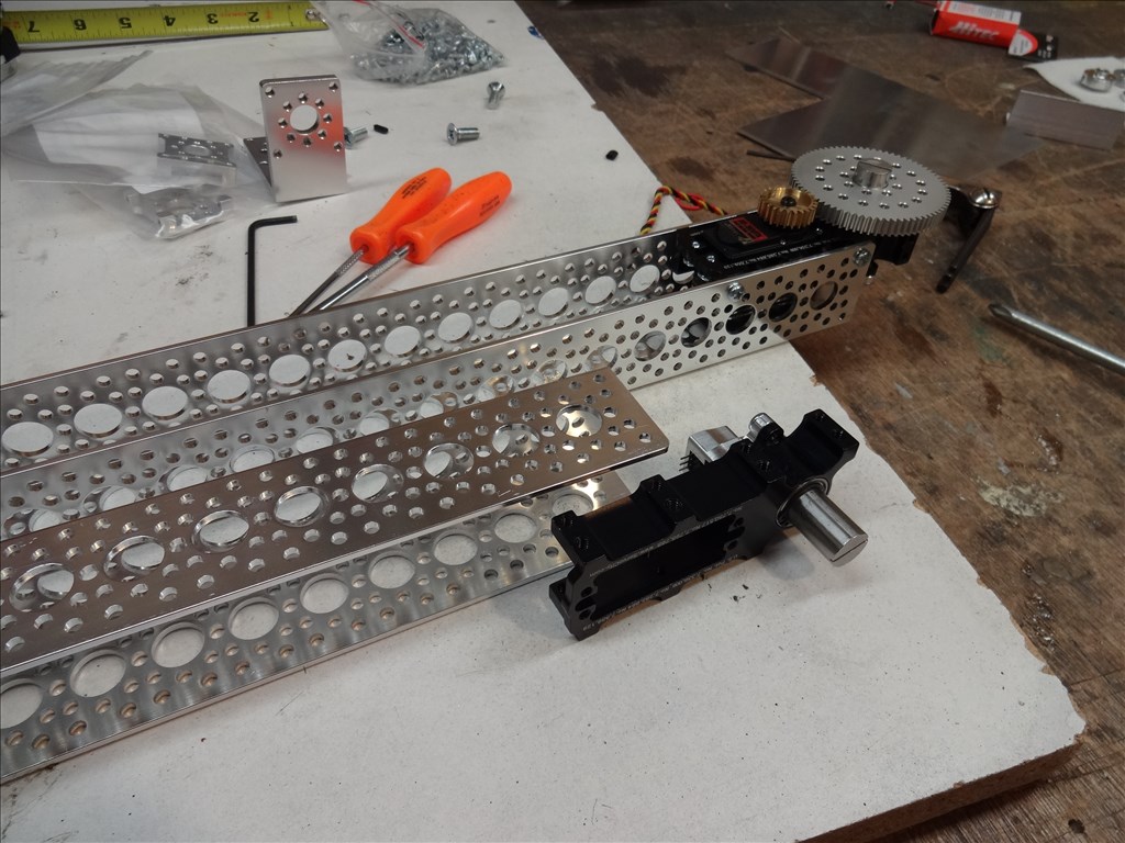
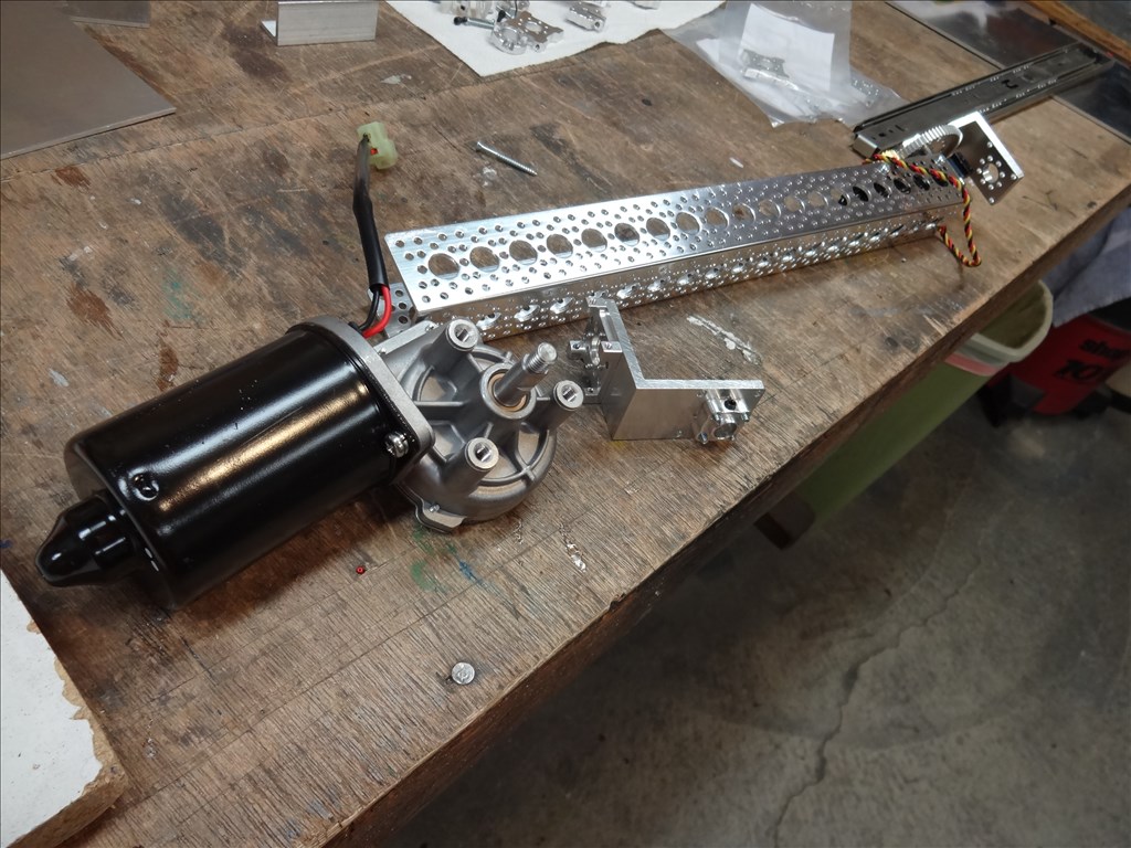
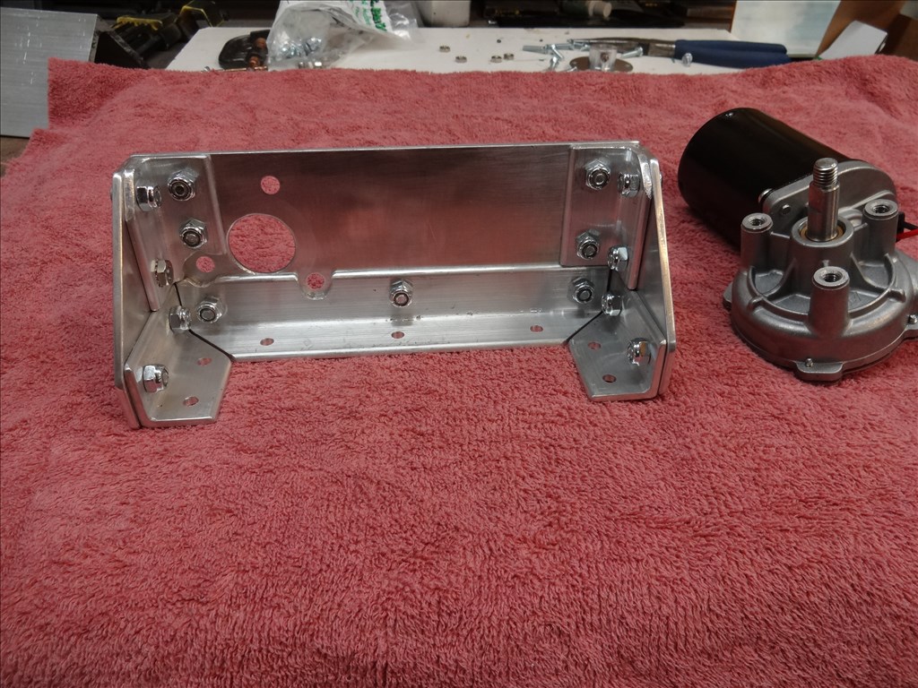
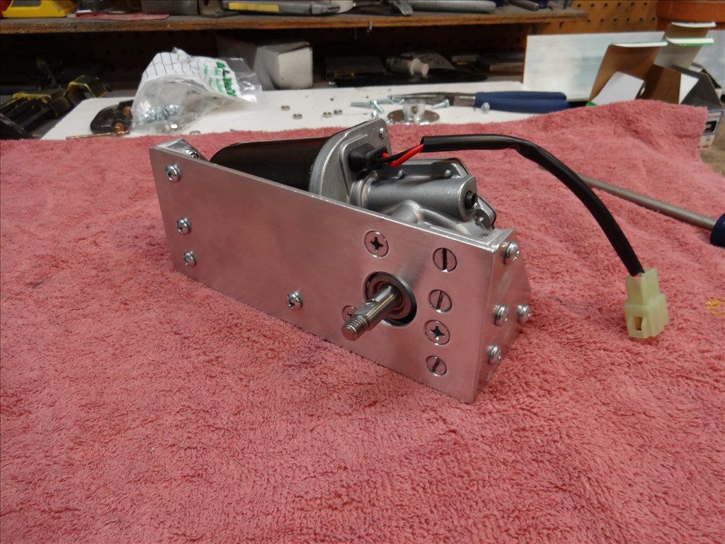
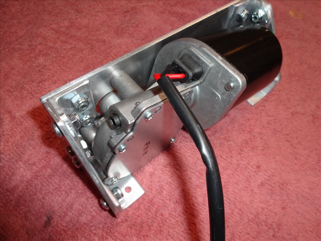
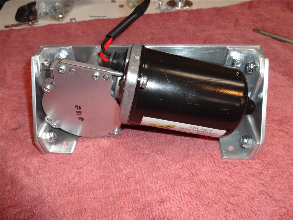
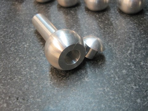
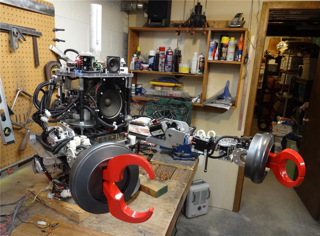
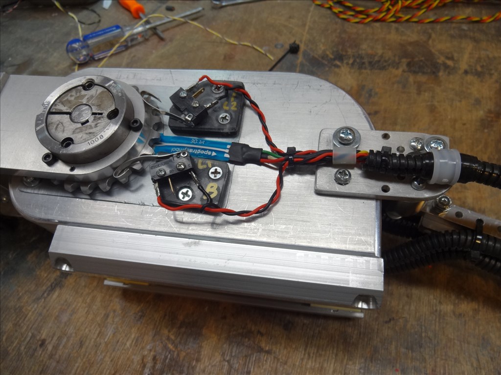
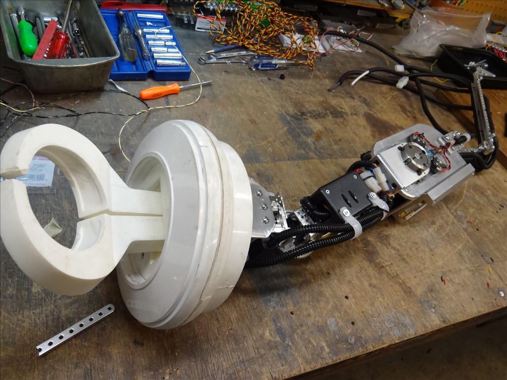
The elbow is a universal joint from a steering column. I am using them because I have a matched pair of them. This could actually be replaced by a short, stiff, spring if one wanted to go that route. The cables are thicker than they should be, and they are attached to makeshift spools in a haphazard fashion right now, but it works pretty well. Like I said, it is kind of a proof of concept right now. The windshield wiper motors seem to move it at about the right speed and torque.
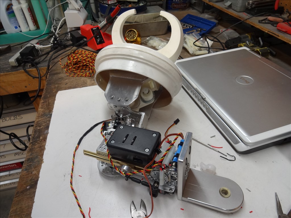
The arm itself, as you can see is a collection of PVC parts. It is lightweight but strong enough for what it will be doing. If anyone is interested in the details I can explain what parts I used and how they fit together.
I do plan on putting a wrist joint out on the end of it. It will only pivot up and down. To move them I have push/pull cables that will be powered by motors and levers inside the body, again to keep the weight off of the arms. To open and close the claws, I could also use small cables, but actuators to do that would be fairly light. I haven't decided whether or not they will be in the arms, or in the torso.
Finally, to rotate the claws, I will need small motors in the claw mechanism. I do not see how to avoid that.
It is still a work in progress, but I know that you are trying to get ideas for your arms. Perhaps this will help.
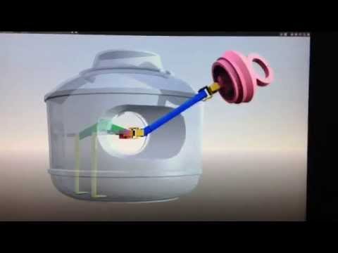
(I am also including an early concept cg diagram that I made before I started).
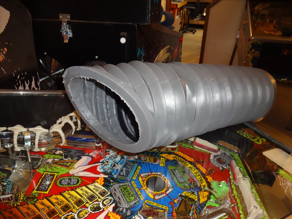
@ Danger! Brilliant engineering and use of what you have there to use! I love the idea of a universal joint for the elbow and PVC as a support system. The Round material will allow movement without snagging on the bellows of the arm. Looking at screen shots of where the elbow actually flexes on the robot it's not really too far out. I'd guess about 5" past the opening. Take a look:
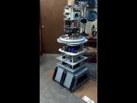
I also like the cabling. That should help the arms to move an any direction. I had been thinking of this myself but worry about snagging on the inside of the rubber arm and nor having room. Perhaps I can stream line but I'll still to figure how to remove the whole thing through the arm hole. When I lift the torso off over the central support system it just passes by each shelf. I should have plenty of room in side the torso though of I can remove the unit through the 5 3/4" arm hole.
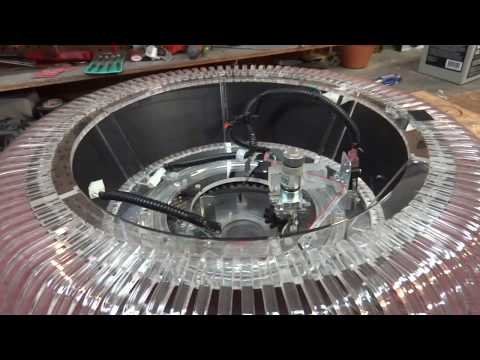
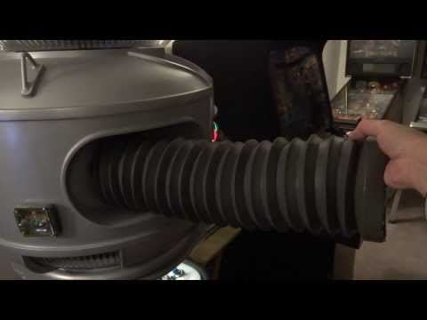
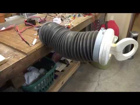
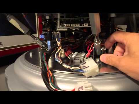
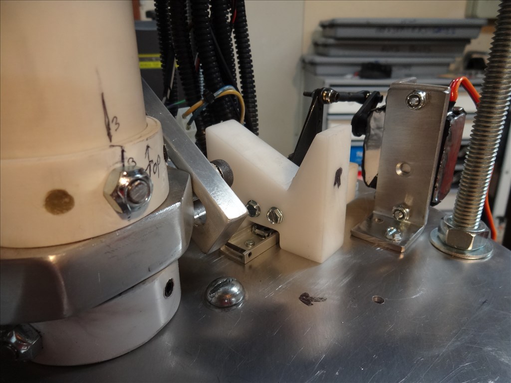
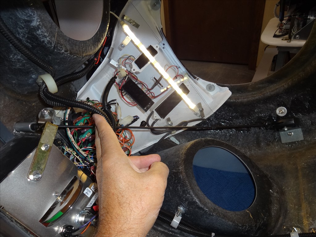
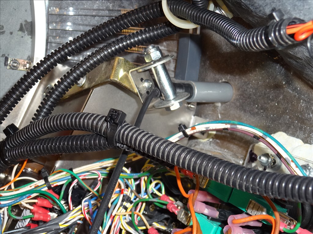
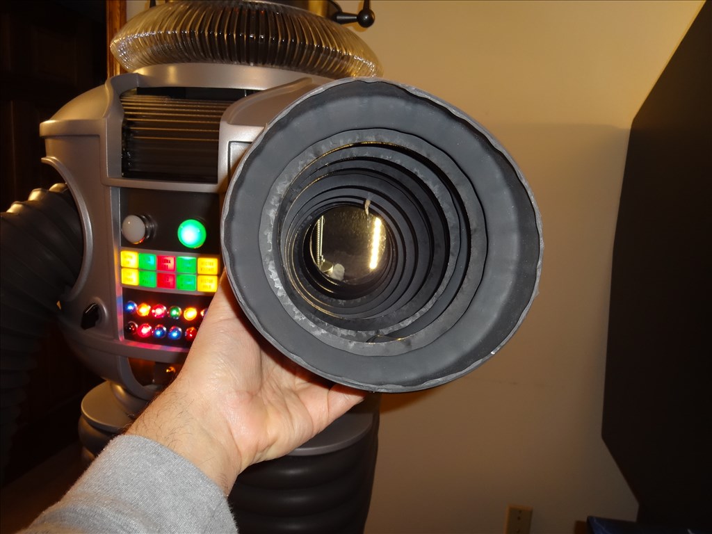
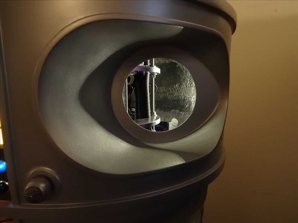
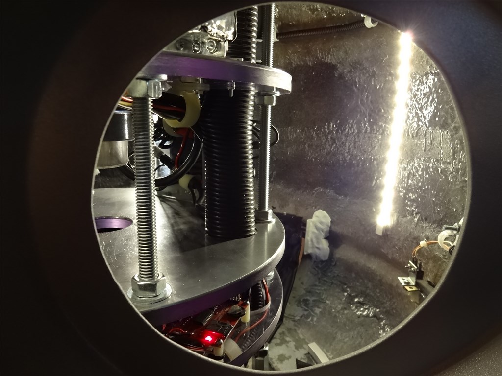
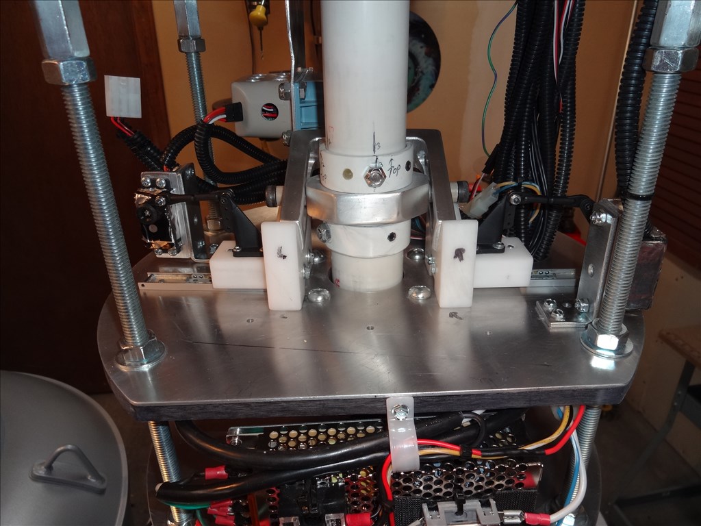
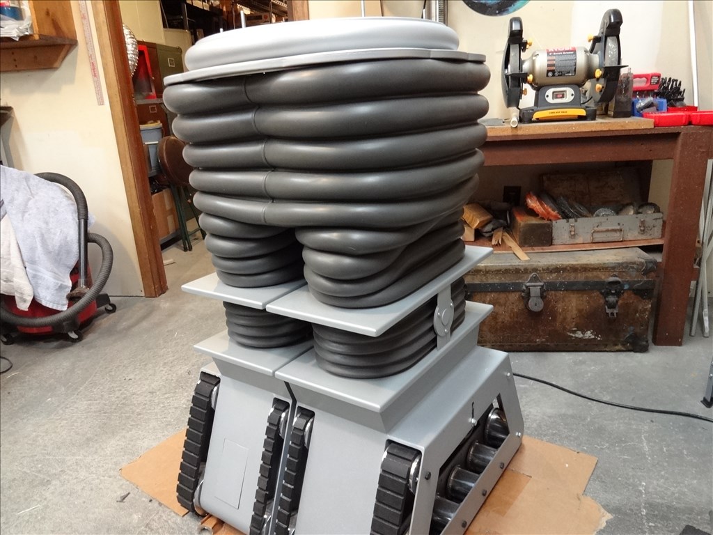
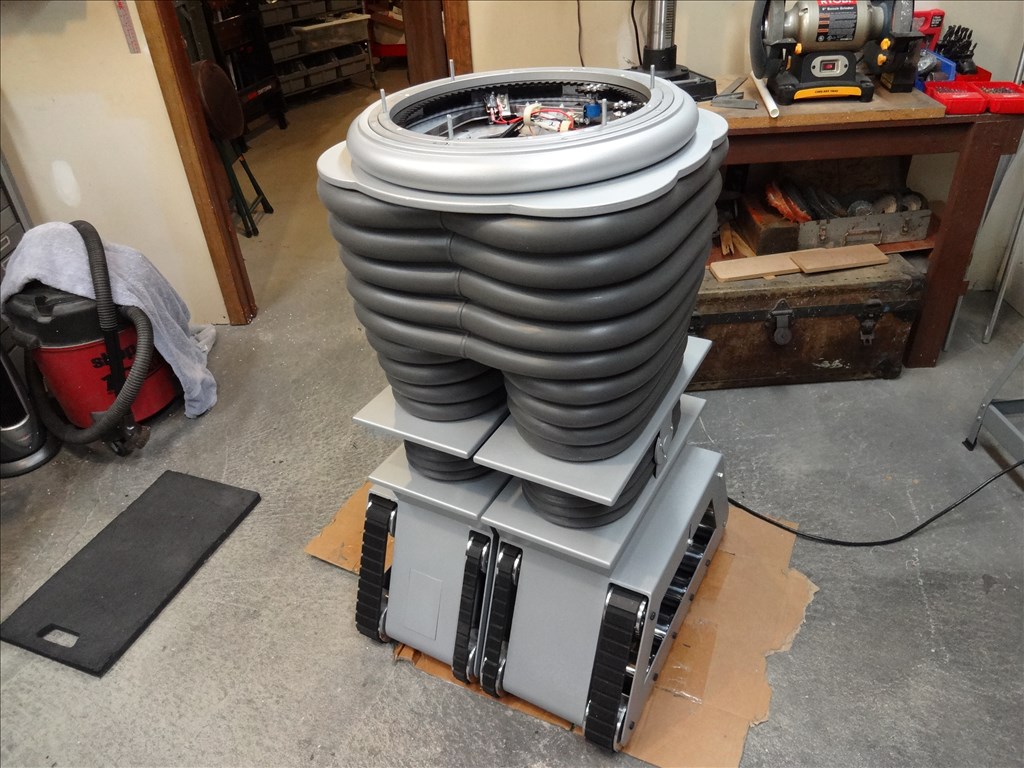
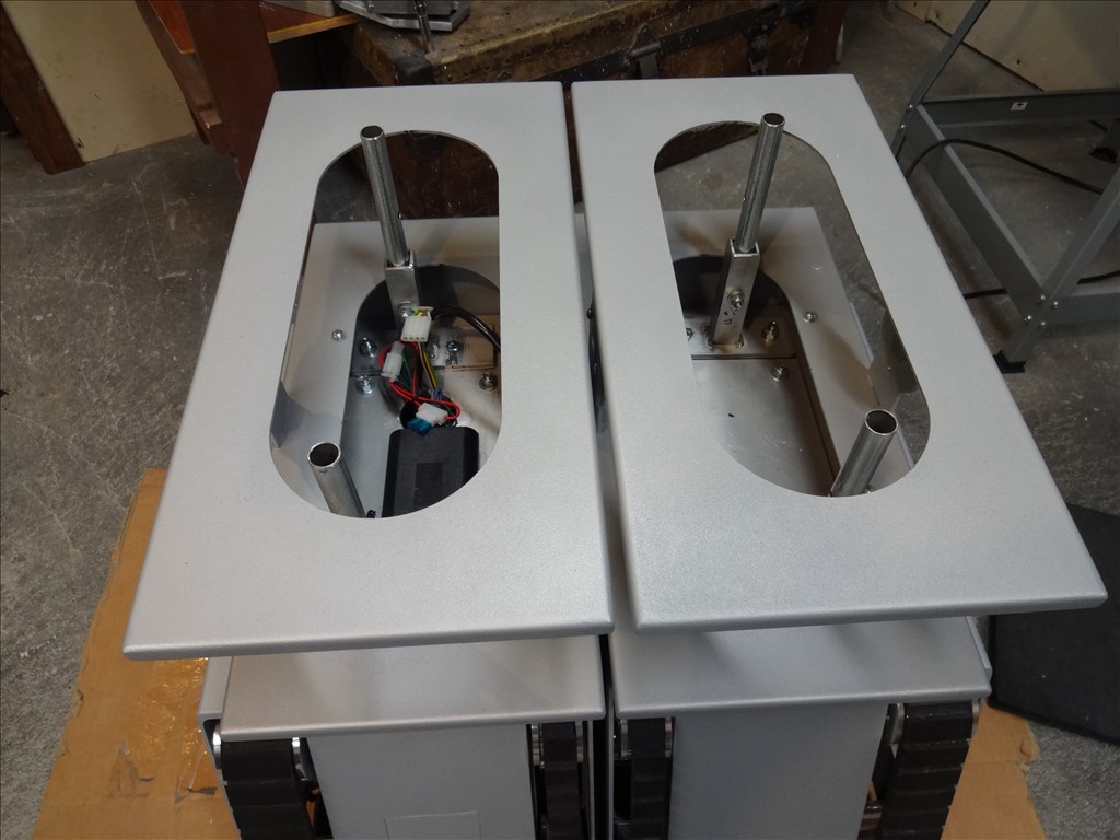
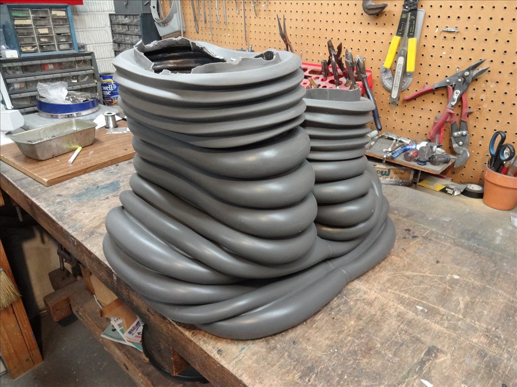
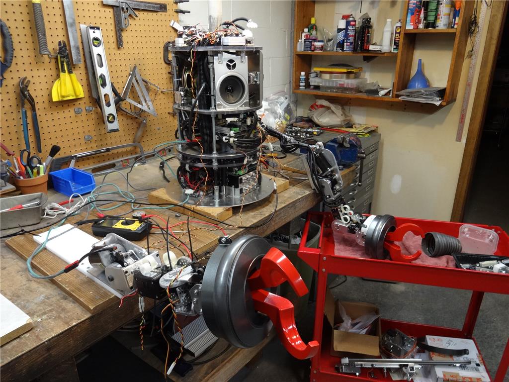
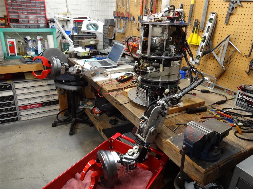
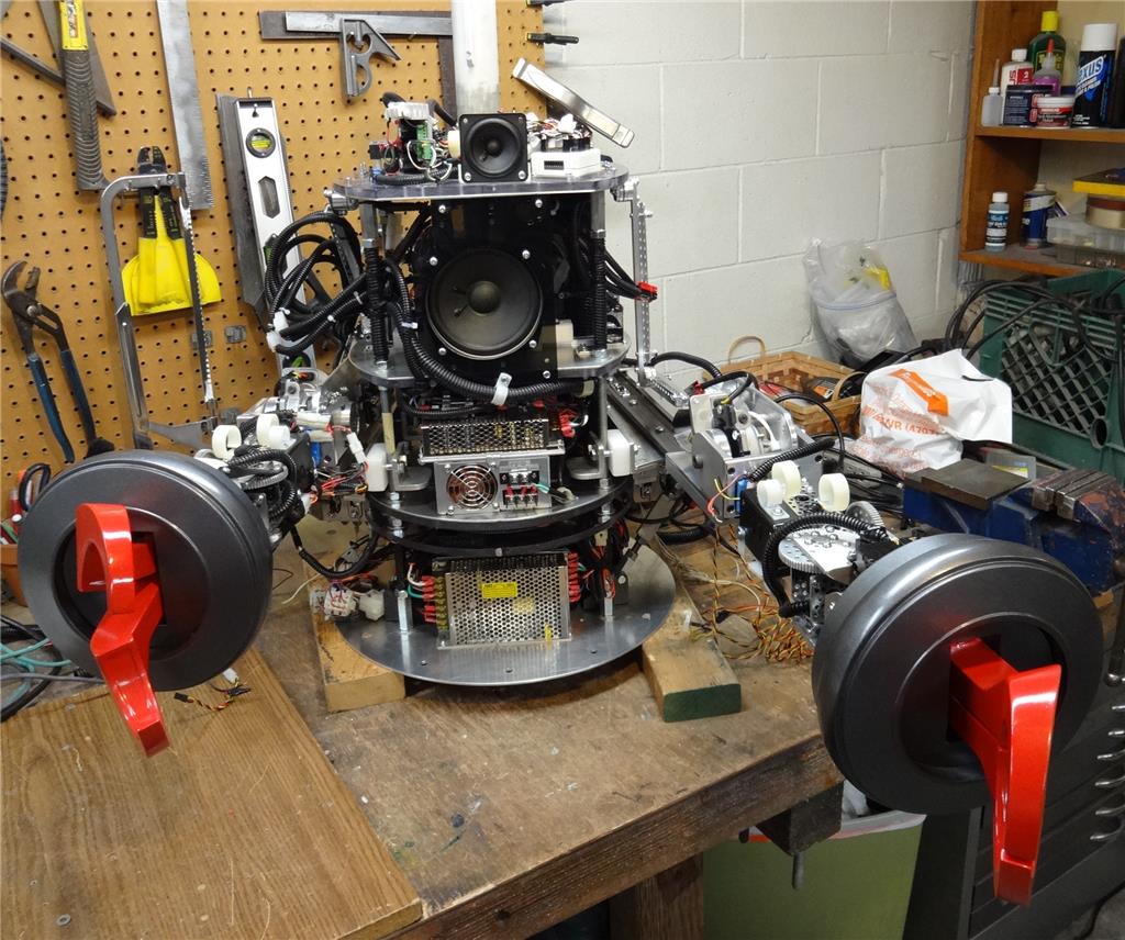
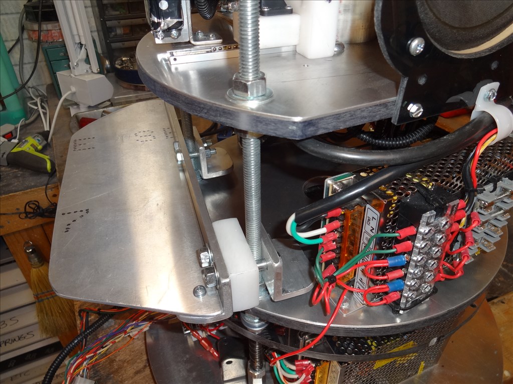
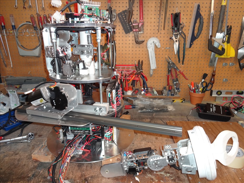
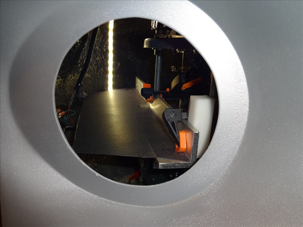
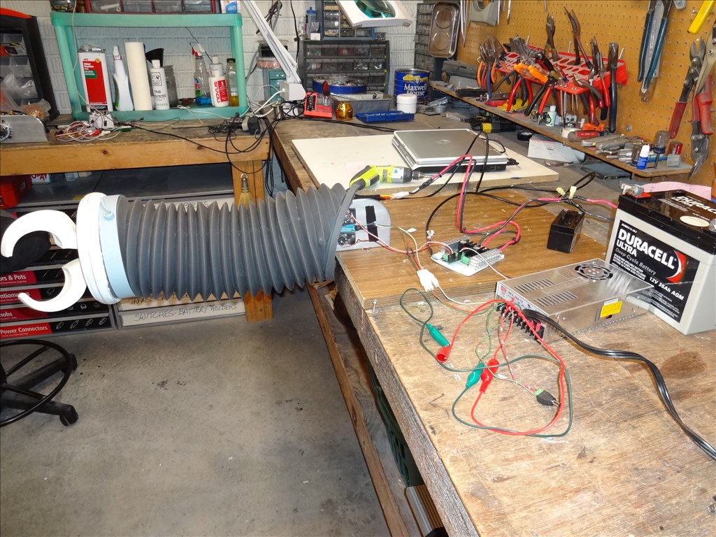
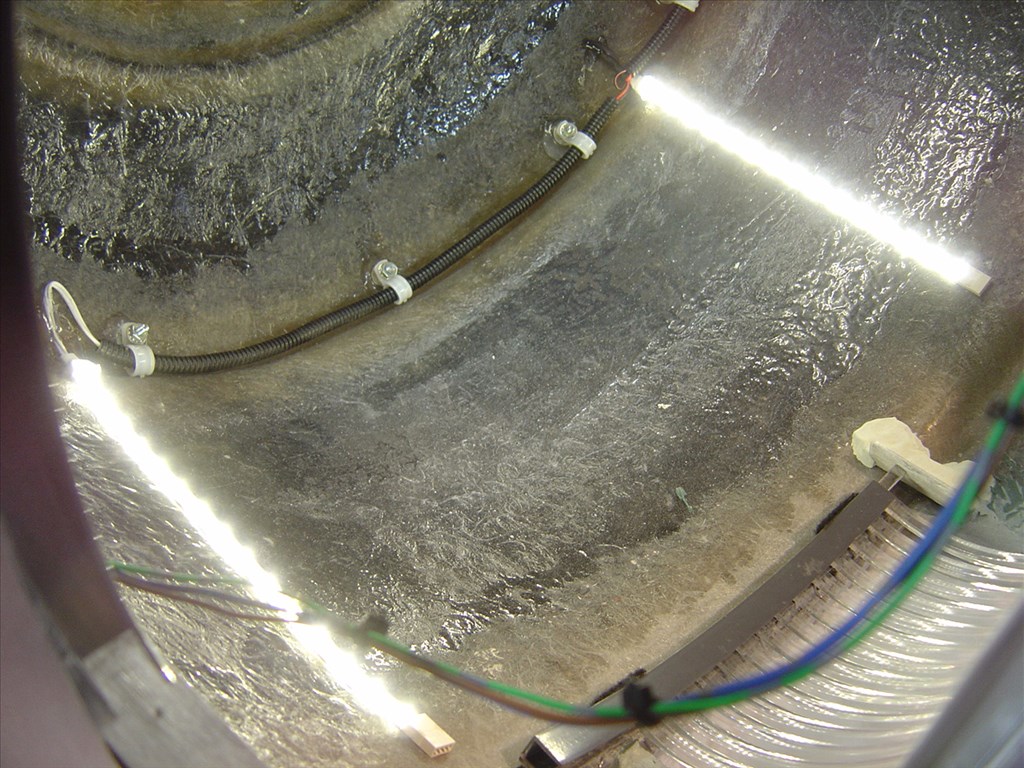
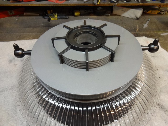
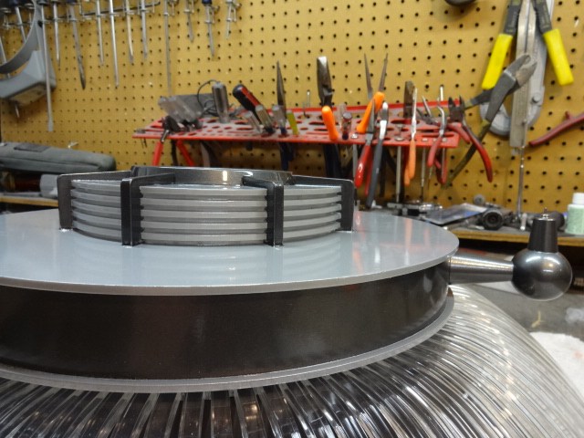
@Rex, Here are the measurements and some more pics of tolerances of what I have to work with:
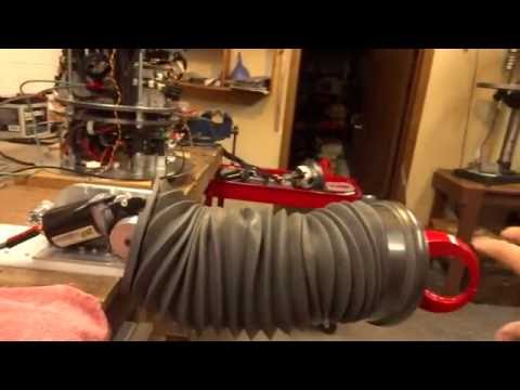
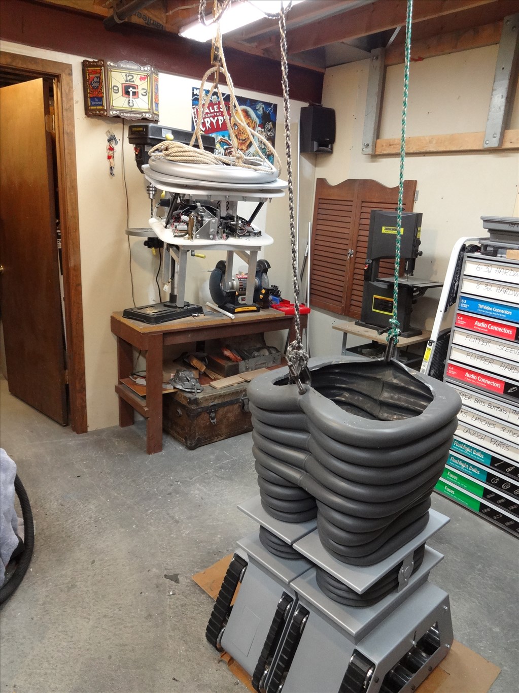
-Inside diameter of rubber arm: 5" -Length when fully retracted - 8" -Length when fully extended - 18" -Distance from torso arm opening to the elbow bending point - I'm guessing about 5" -Distance from elbow to the wrist joint - About 13" -Mounting method to robot torso - Will mount directly to a shelf of the CSS or it's threaded rods. -How much room is there inside the torso for mounting shoulder motor: Depth of torso - 11" to 17" depending on where I measure from arm hole to rear radius of torso wall Width of opening between CSS & Torso wall - 7" at widest point Depth from bottom of arm hope to bottom of torso - 9" but most of this is unusable. -Arm opening - Perfect 5 3/4 round hole. -Does elbow need to bend 90 degrees? - Yes or as close to as possible. -Does shoulder need to rotate more than 90 degrees? - No, Just up and down about 30 degrees or so.
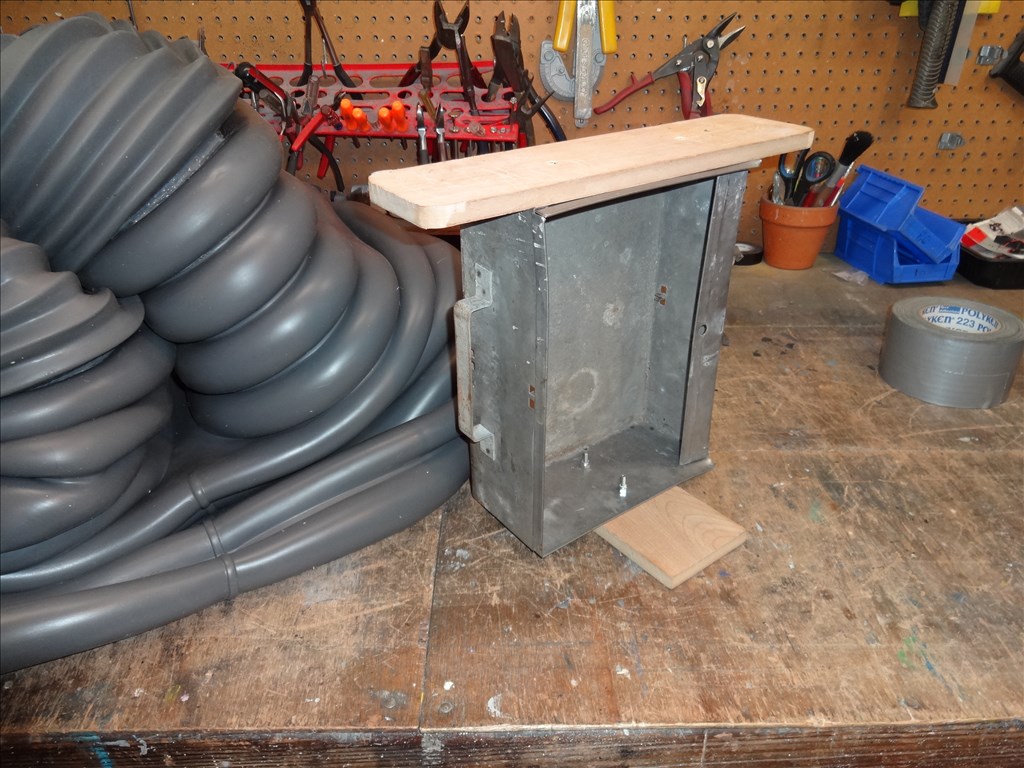
Inside diameter of rubber arm: 5"
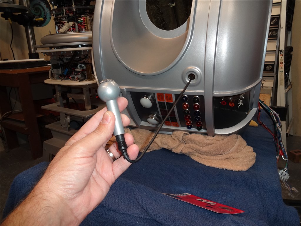
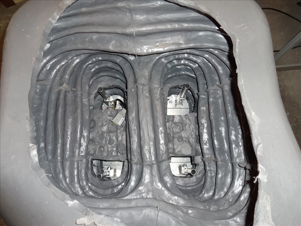
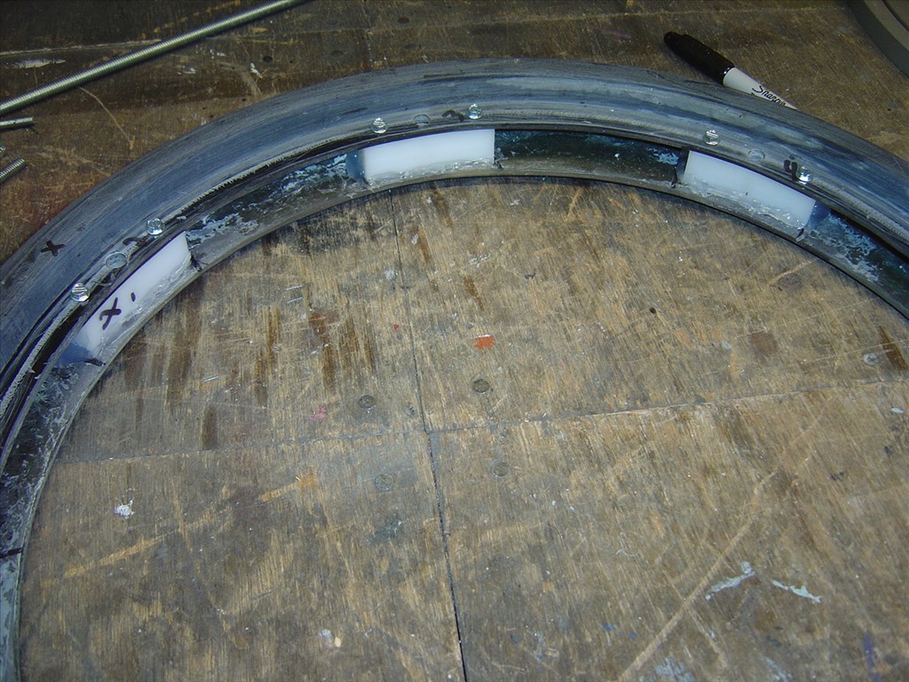
Rubber arm is held on by it's own flange
Arm fully extended at about 18"
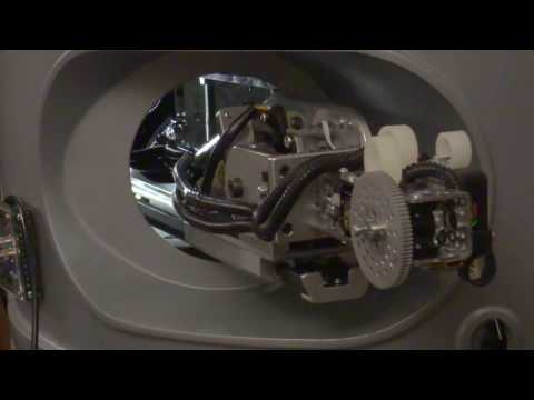
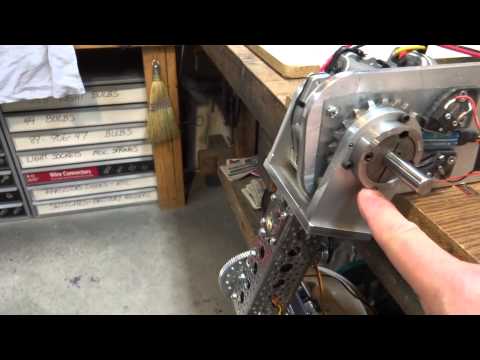
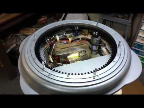
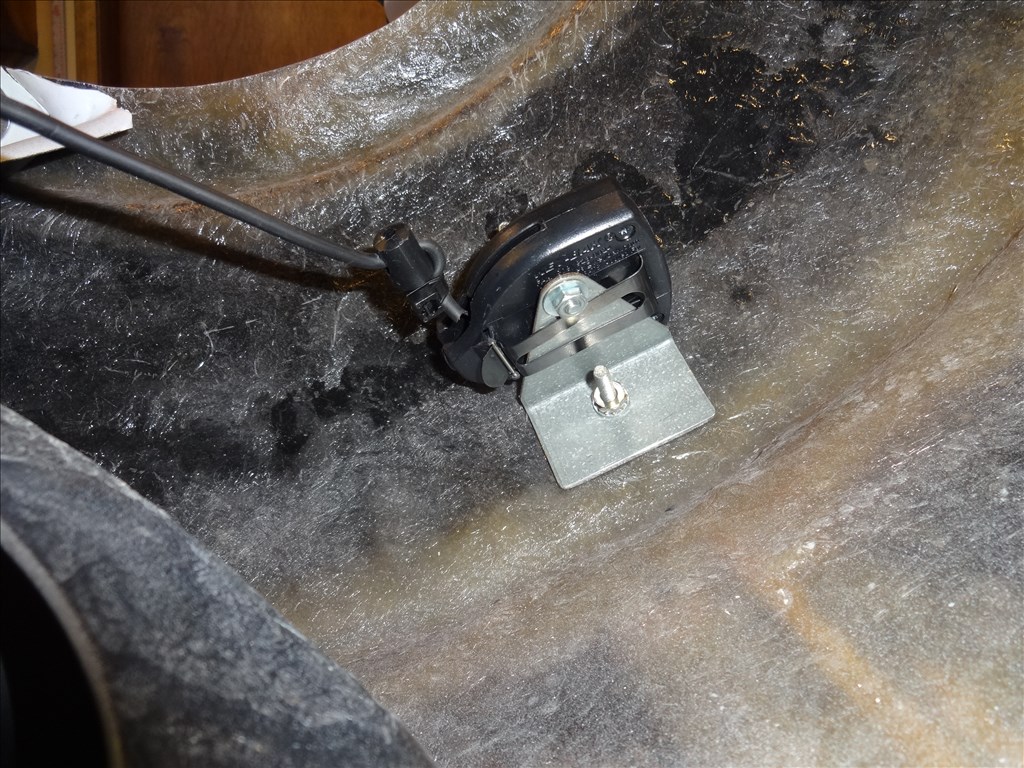
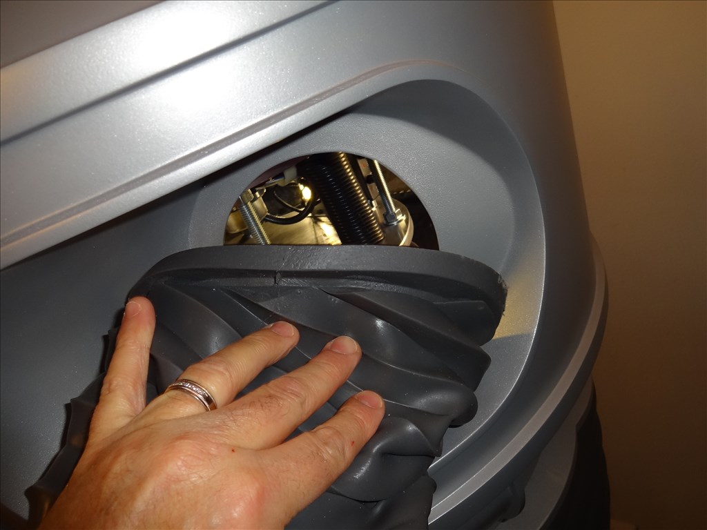
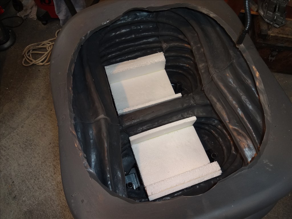
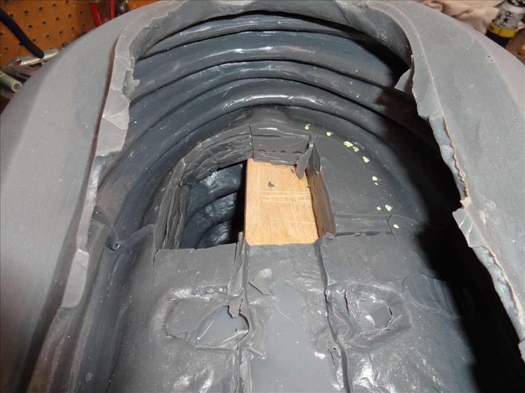
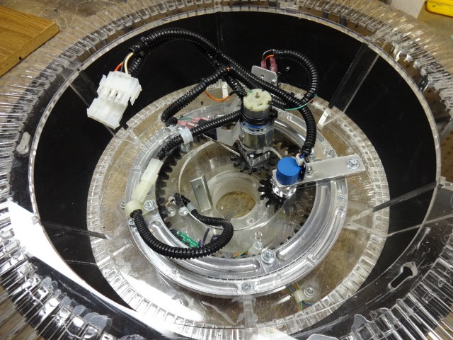
A view of the area where the arm will attach
I want to attach the arm unit to the either a shelf or threaded rods of the CSS
Hope this is all clear. It's great getting help from you guys. Three heads are a lot better then my one feeble mind.
Thanks again!
Thank you for the compliments Dave. I think that my measurements for where the elbow and wrist are, will be about right. I do not know how tall Bob May was, but I am 5' 6". When I stand in front of my robot my eyes about line up with the collar, and my arms with the armholes. I suspect that he was about my height. I got inside my torso and stuck my arms out of the holes and got the measurements for what I have so far.
Incidentally, I did some experimenting with the arm as it is now. It does not move as fast as a human arm does, but at about the speed one would expect from a robot (perhaps two seconds for a full swing from top to bottom). It can lift a five pound weight at the end of the existing arm without difficulty. That was running off of a small battery charger. He may do better with a real battery. He won't be shoveling snow, or moving furniture, but he will be able to shake hands or pass out beer at a cookout.
Hopefully you'll invite me to one of those cookouts. I'd love to get served a cold one by your B9.
BTW, what's your measurement from the torso arm hole to the elbow?
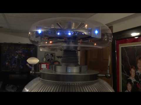
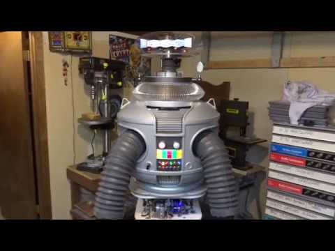
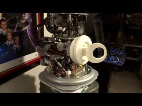
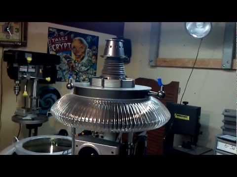
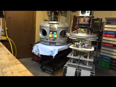
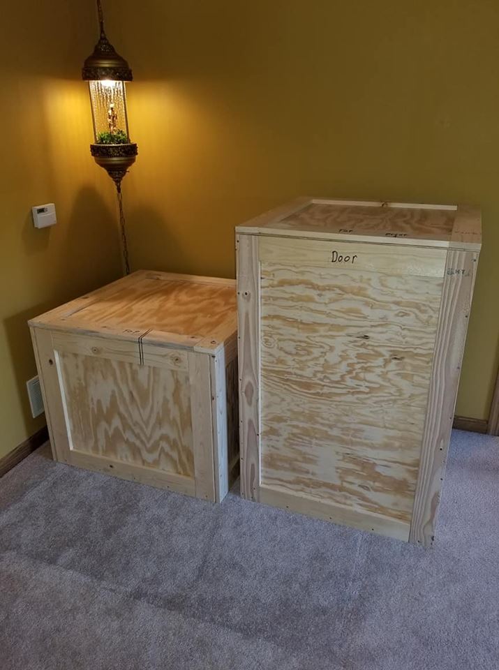
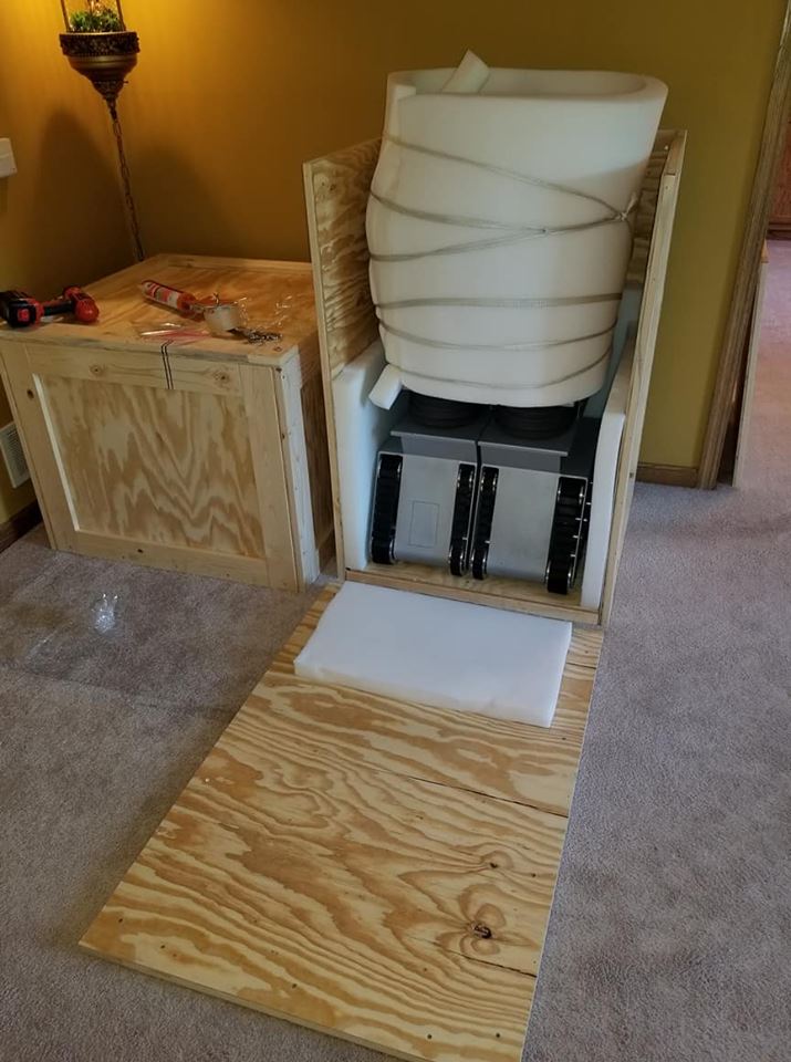
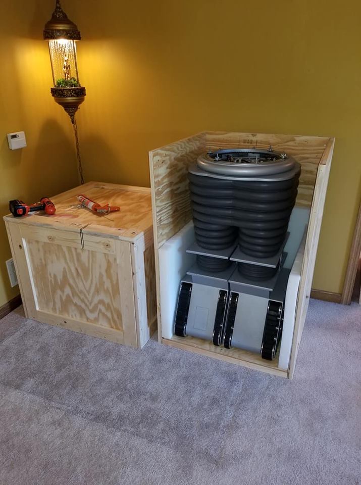
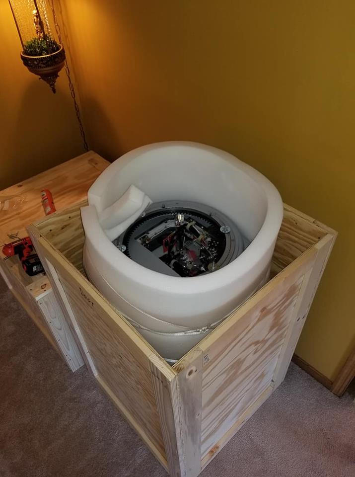
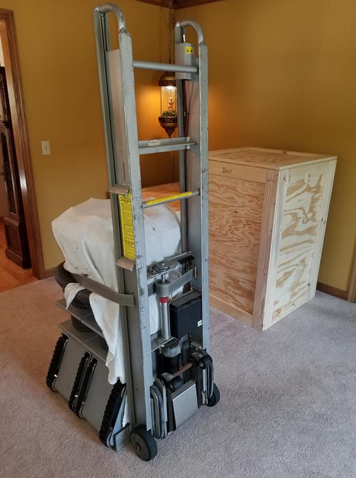
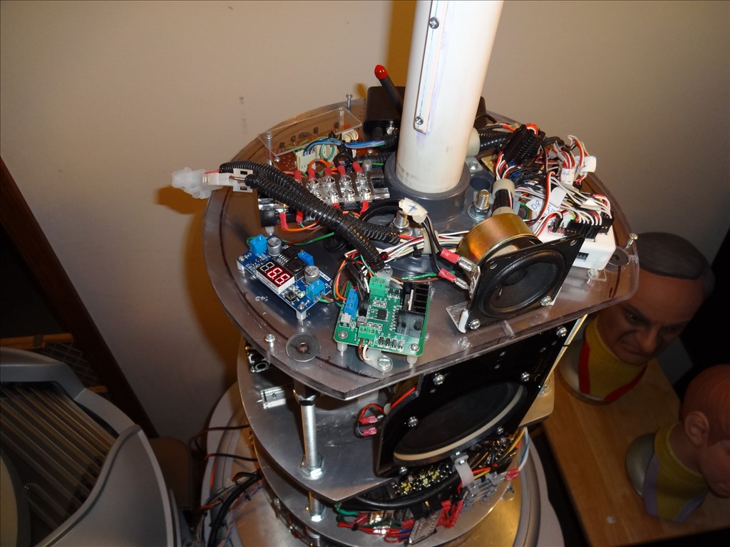
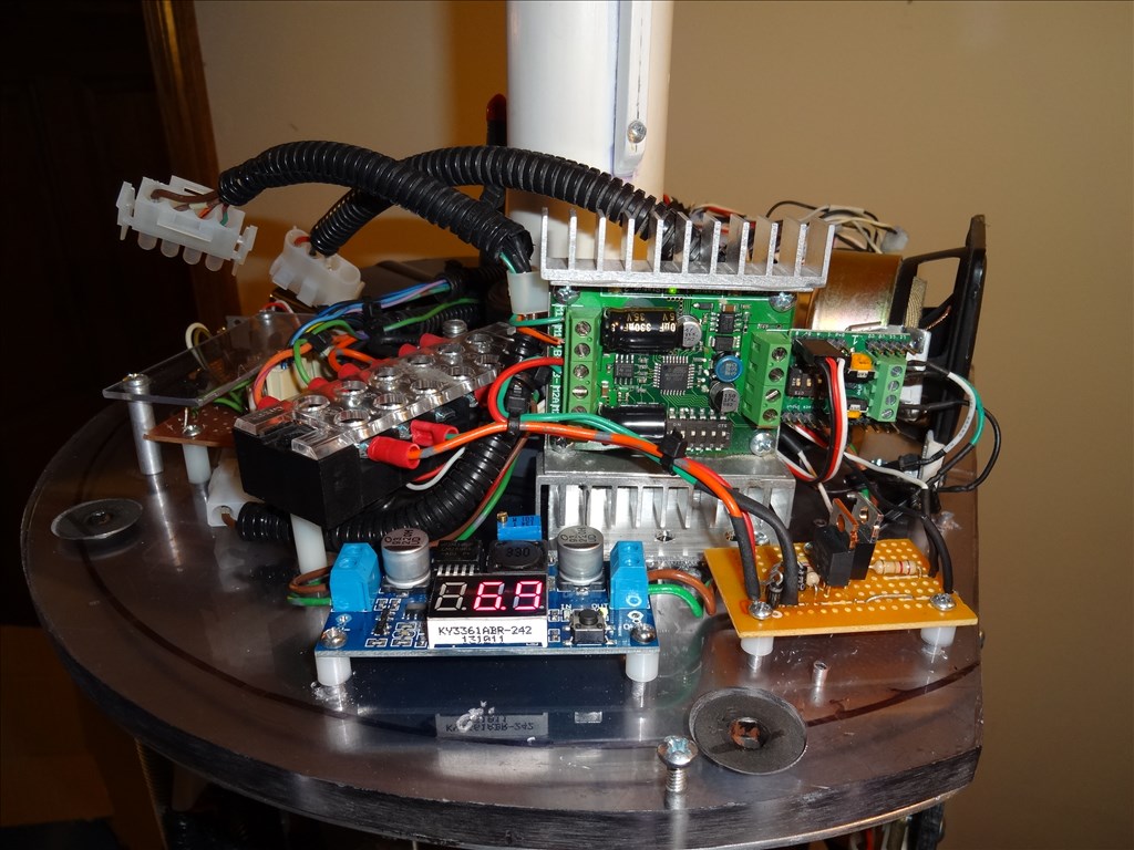
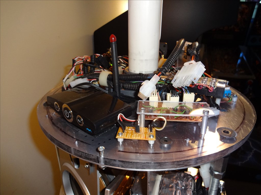
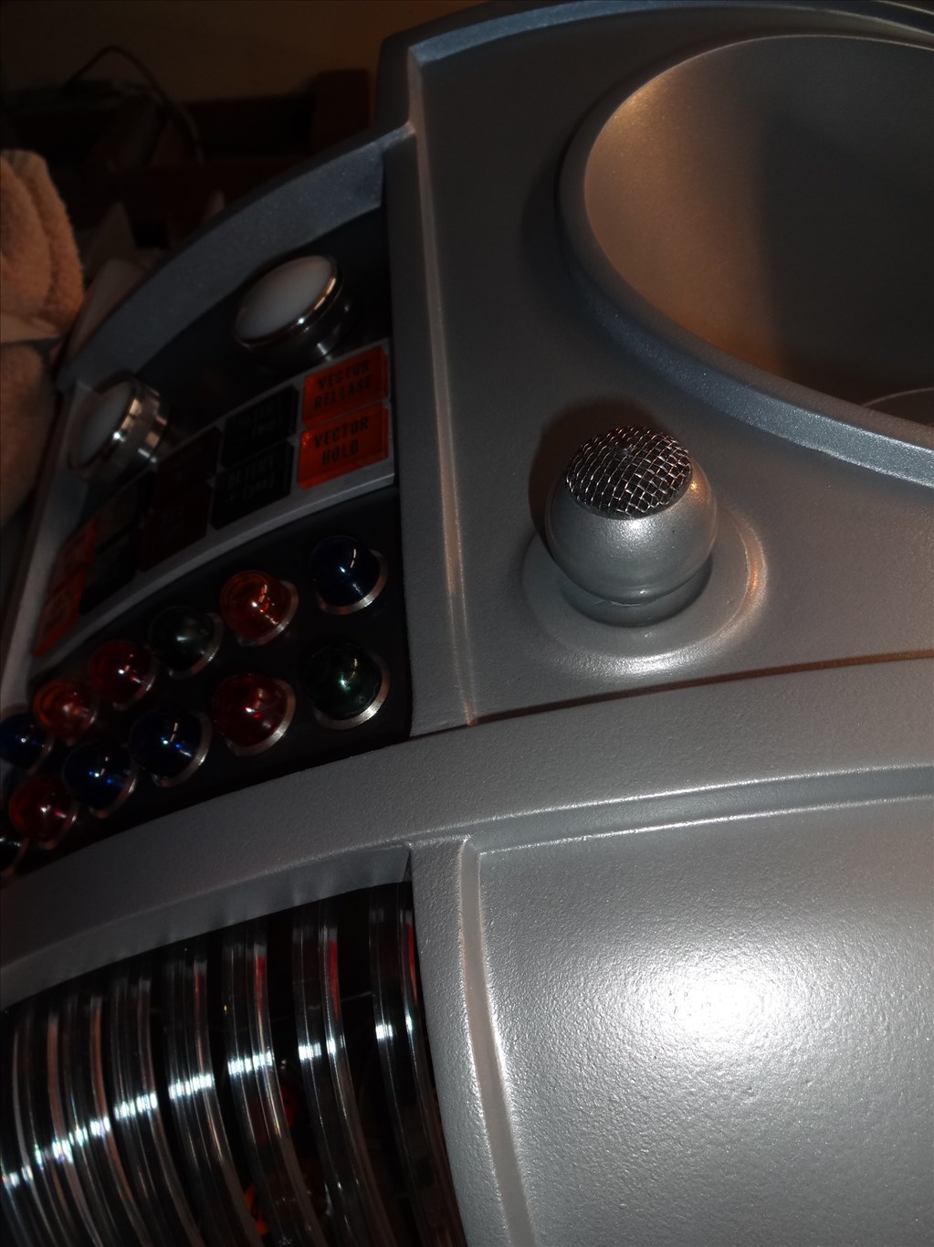
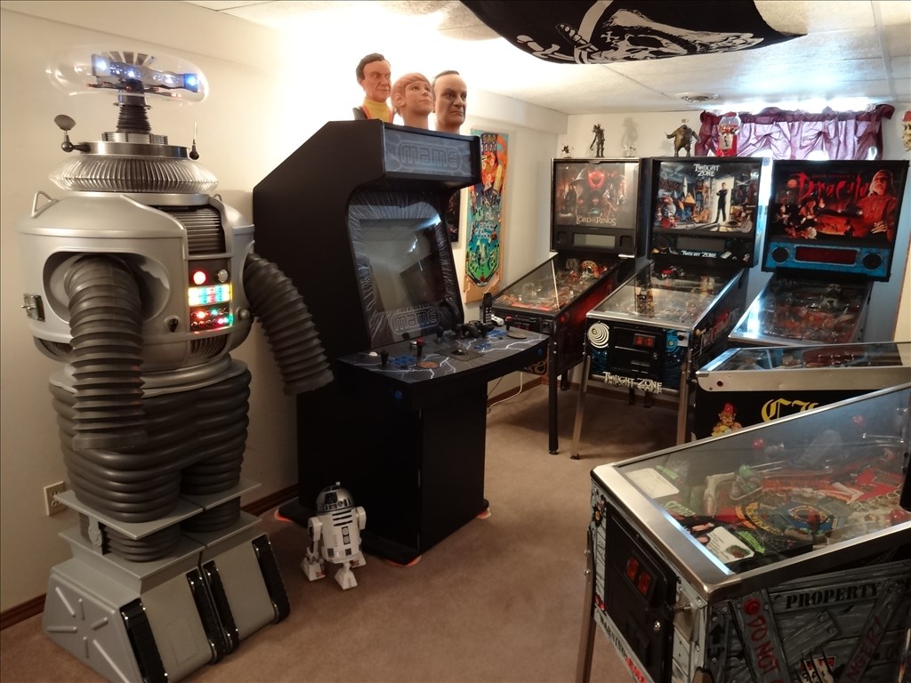
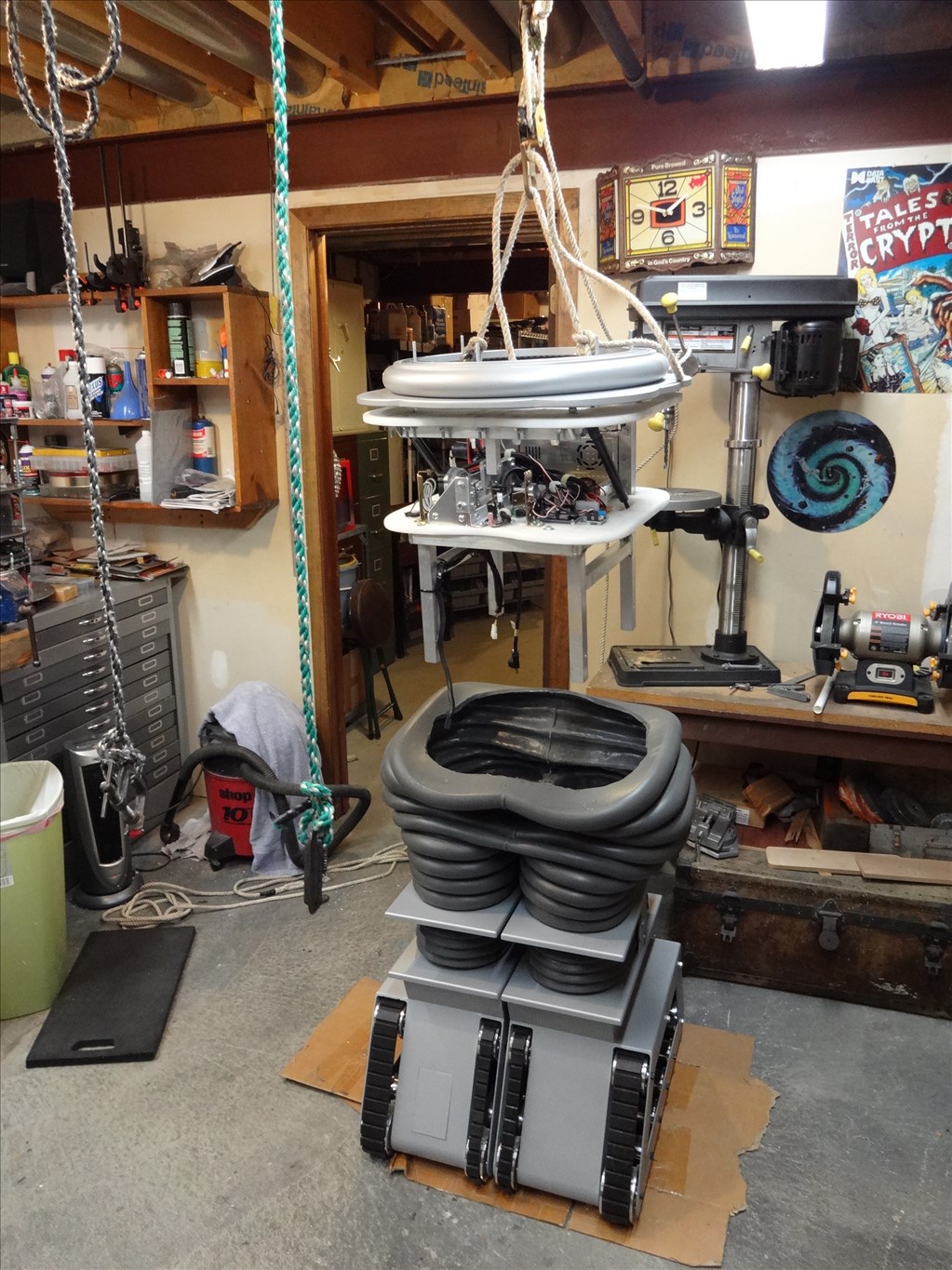
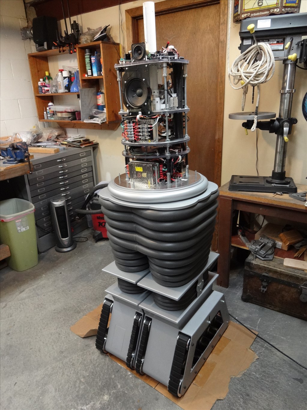
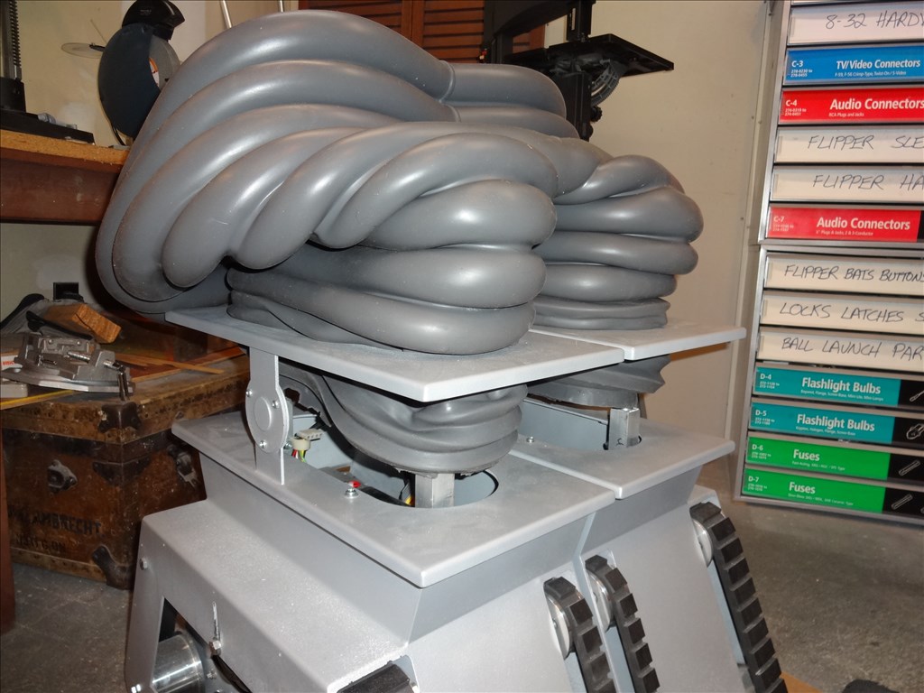
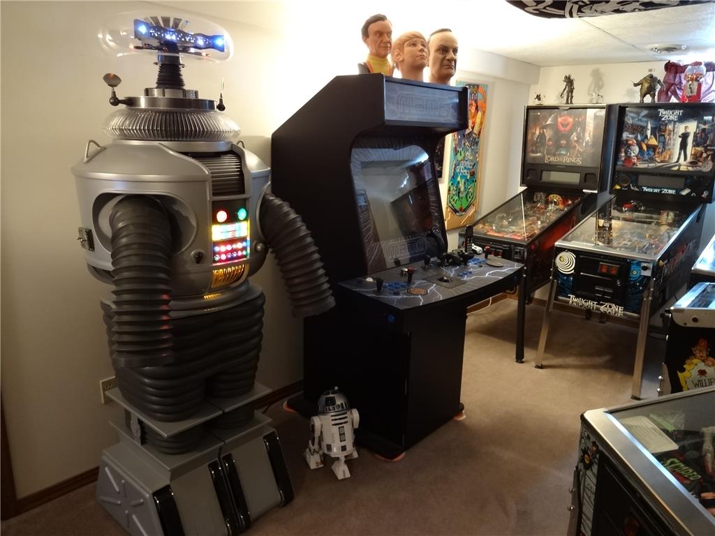
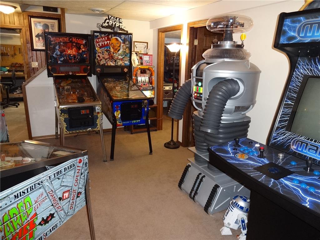
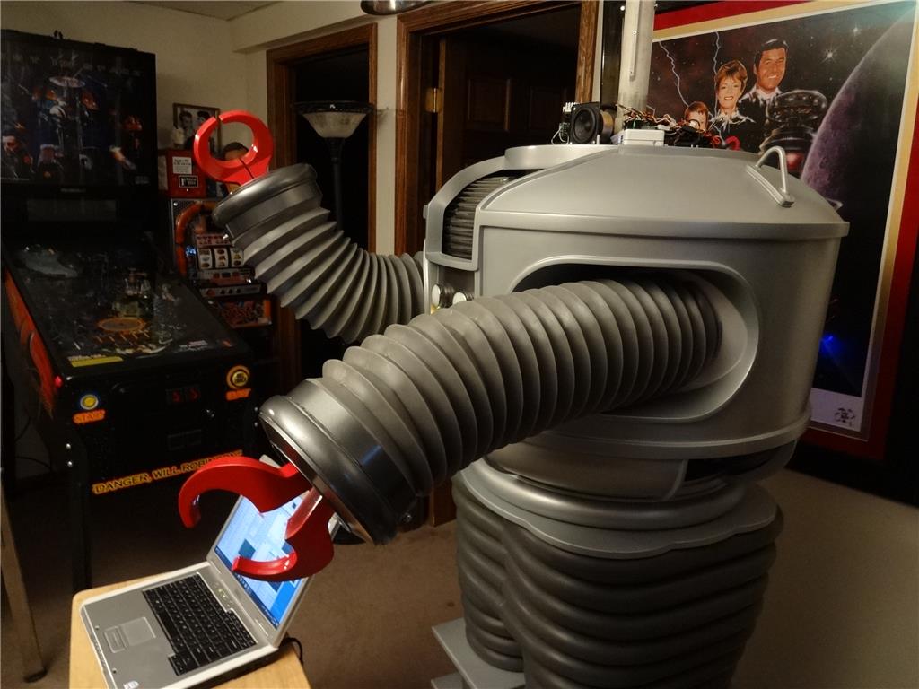
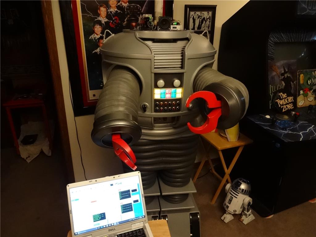
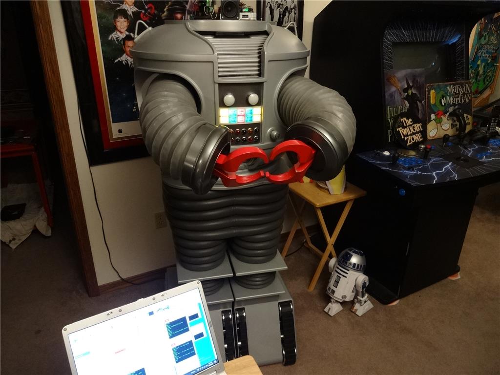
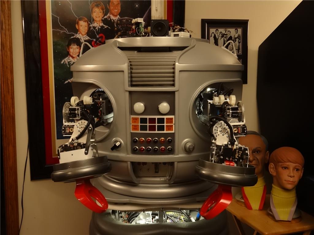
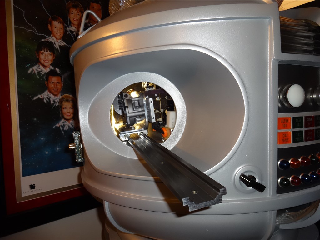
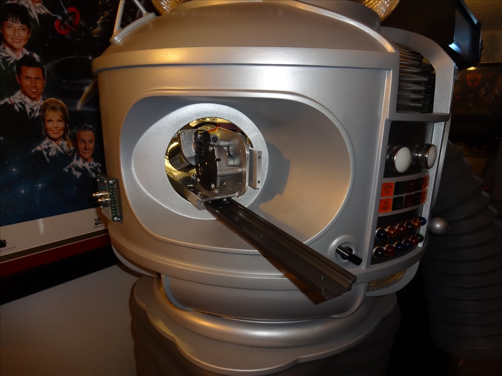
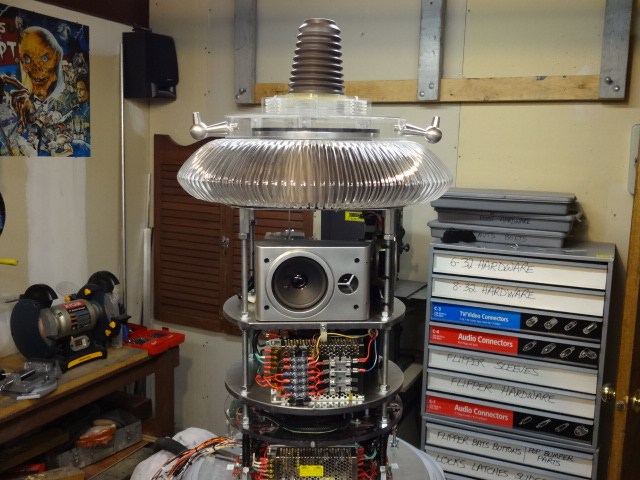
A few months ago I moved B9 from the shop in his temp home in my game room while he awaits his arms. Looks like he kinda like it standing among the other classic items:
Those heads are kinda creepy!
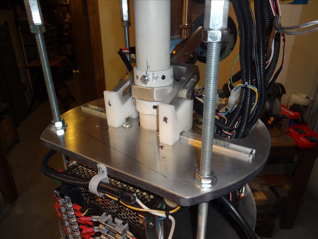
Dave I am still looking for the pictures of the shoulder joint for Magnus. Until then I will post a crude Microsoft Word drawing of it. I hope it is clear enough to follow. I think we have a different idea of shoulder joint movement. The one I have for Magnus travels in an arc. I think by your statement earlier you are wanting an up and down type movement of about 30 degrees? Even though this may not work for your robot it may serve to give you some ideas. I am in process of trying to come up with some new extend and elbow methods.
Thanks for the drawing Rex. I see where your going with this. You show your arms moving back and forth like they are waving to someone. I was talking about up and down movement but perhaps your idea and design could be incorporated also. Your drawing is very clear and helpful.
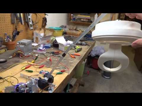
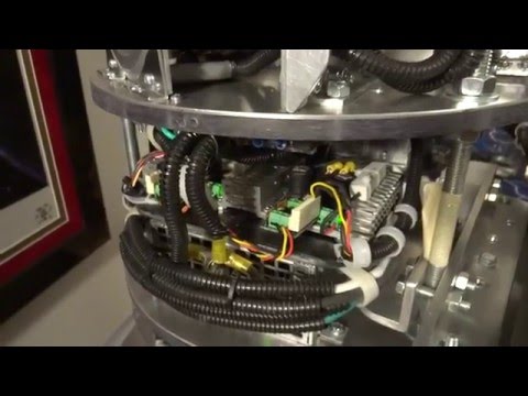
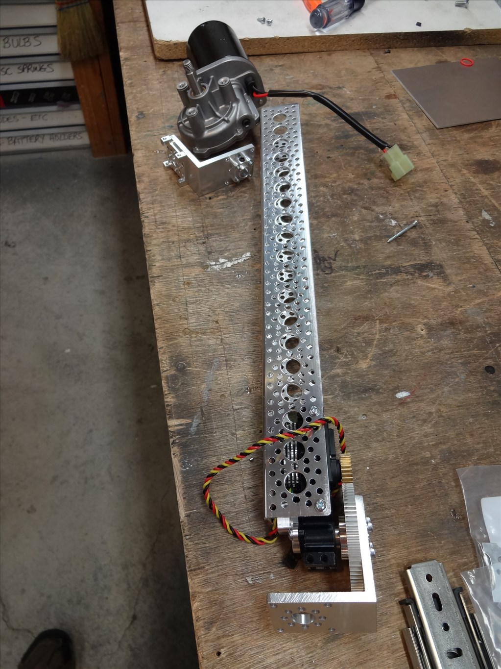
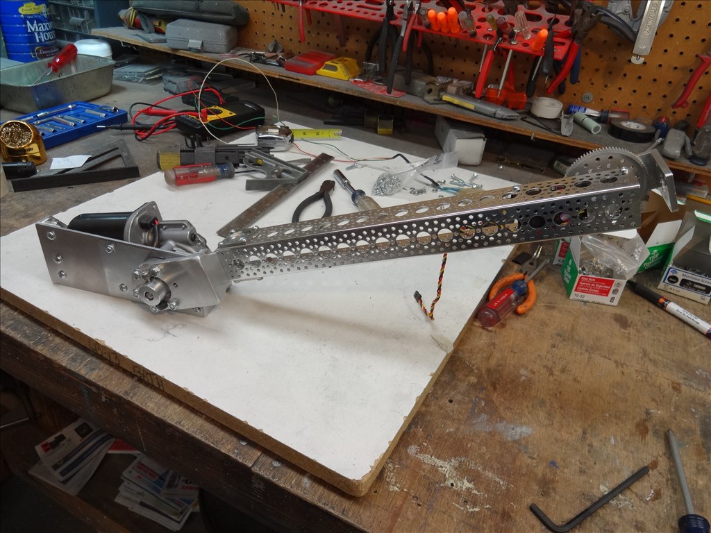
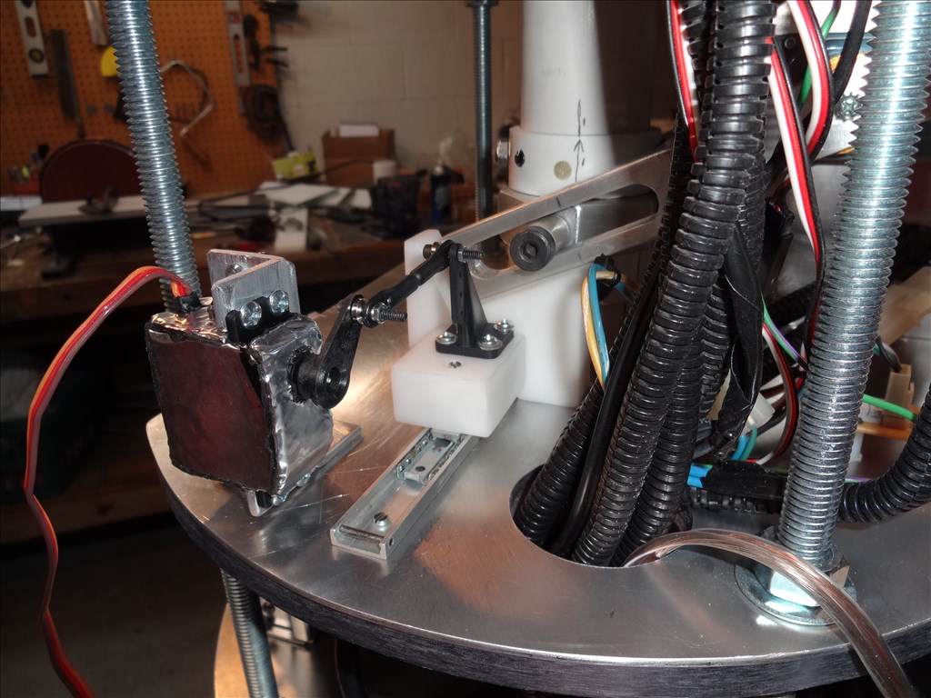
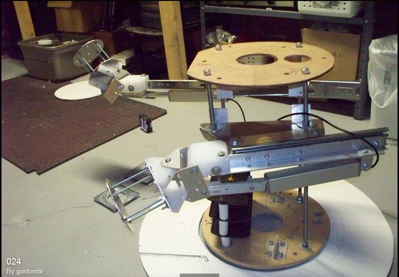
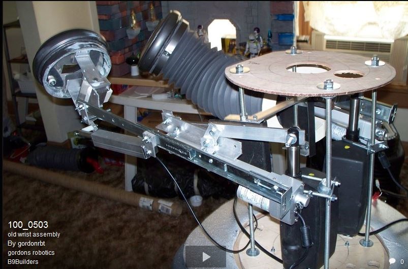
I was pouring over pictures on the B9 Builders Yahoo site and found a recent addition of an arm build that may be just what I'm looking for. It looks like it moves in all the needed directions except up and down but that my be easily added. The best part is it looks like the builder is close to my location so I may be able to meet with him. Here's a picture:
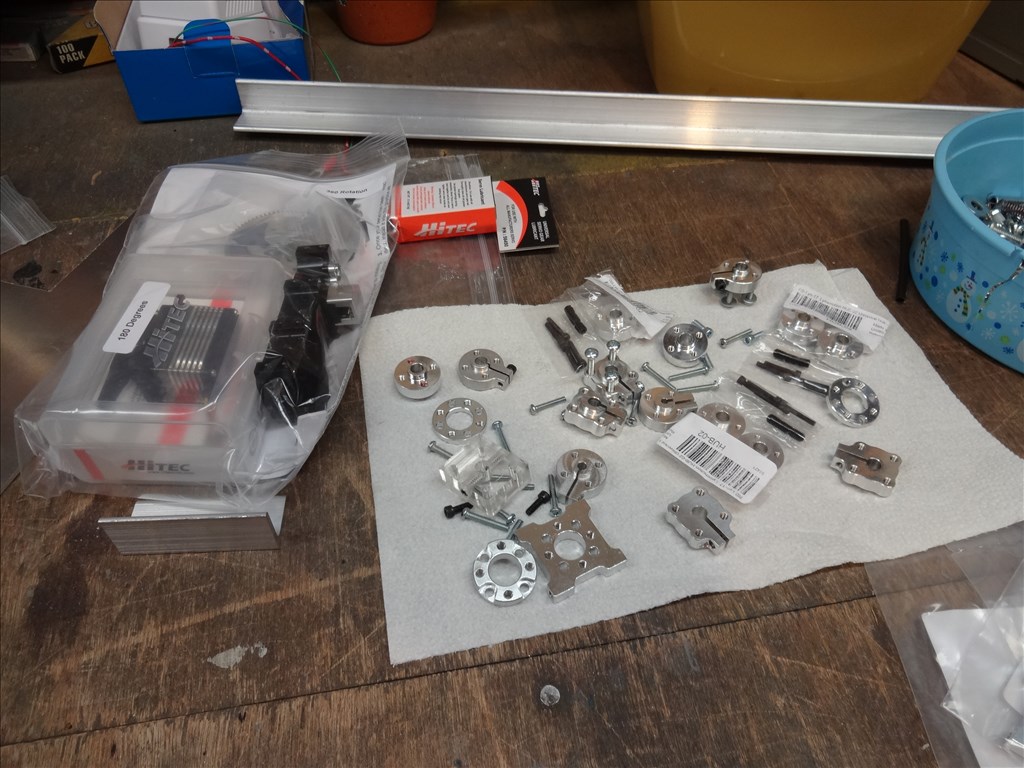
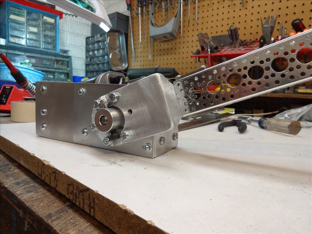
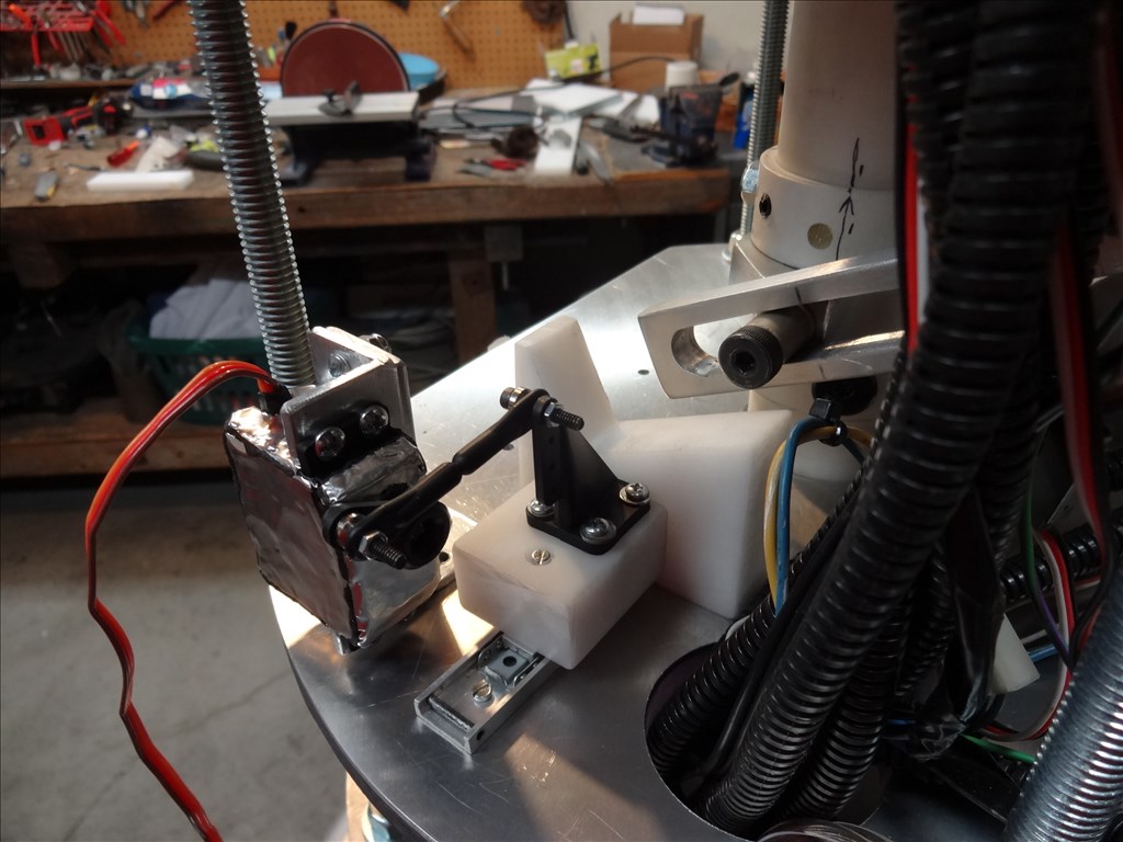
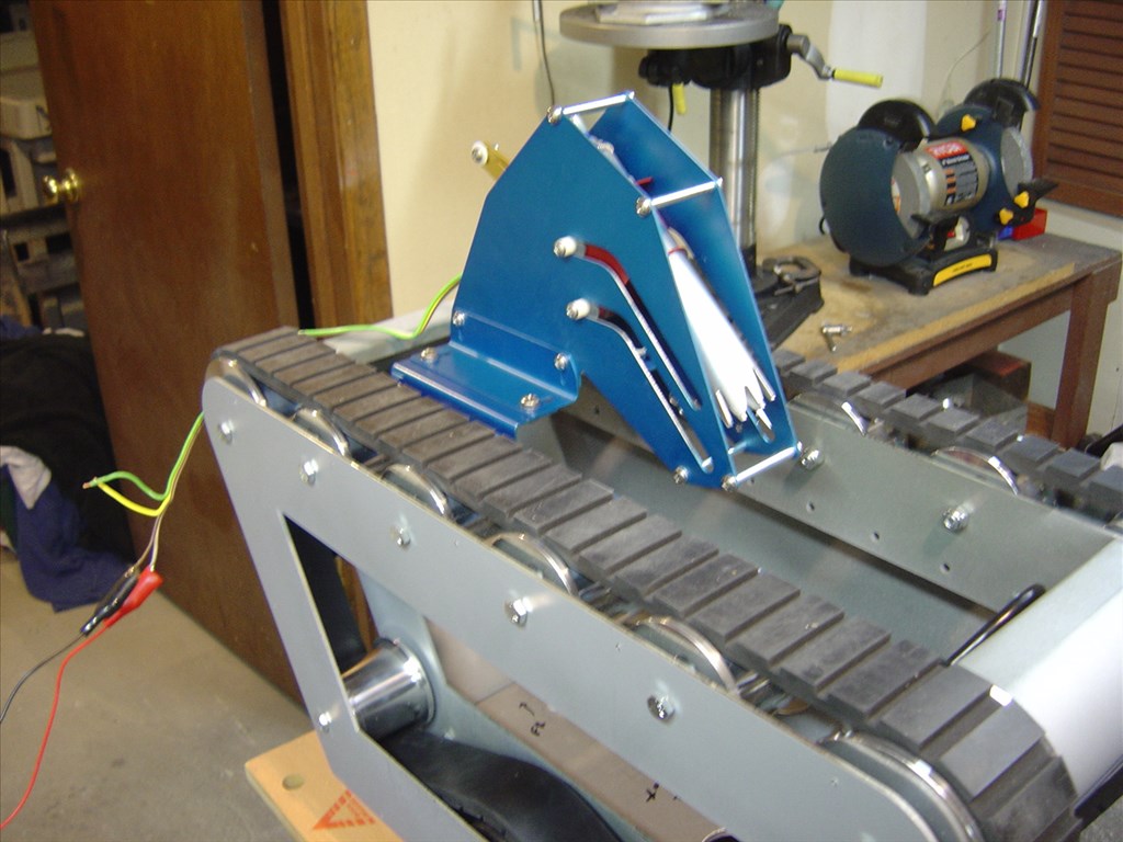
Here's another version by the same builder. Not sure if it's 1st or 2nd gen:
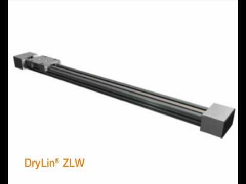
Seems most of the in and out action is handled by Linear Actuators.