
Hello everyone,
I would like to share the new custom firmware available for EZB 4.
Currently i'm beta testing the firmware fixing and polishing the code.
I'm still open for ideas, please comment.
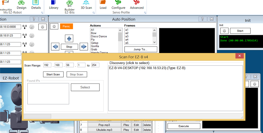
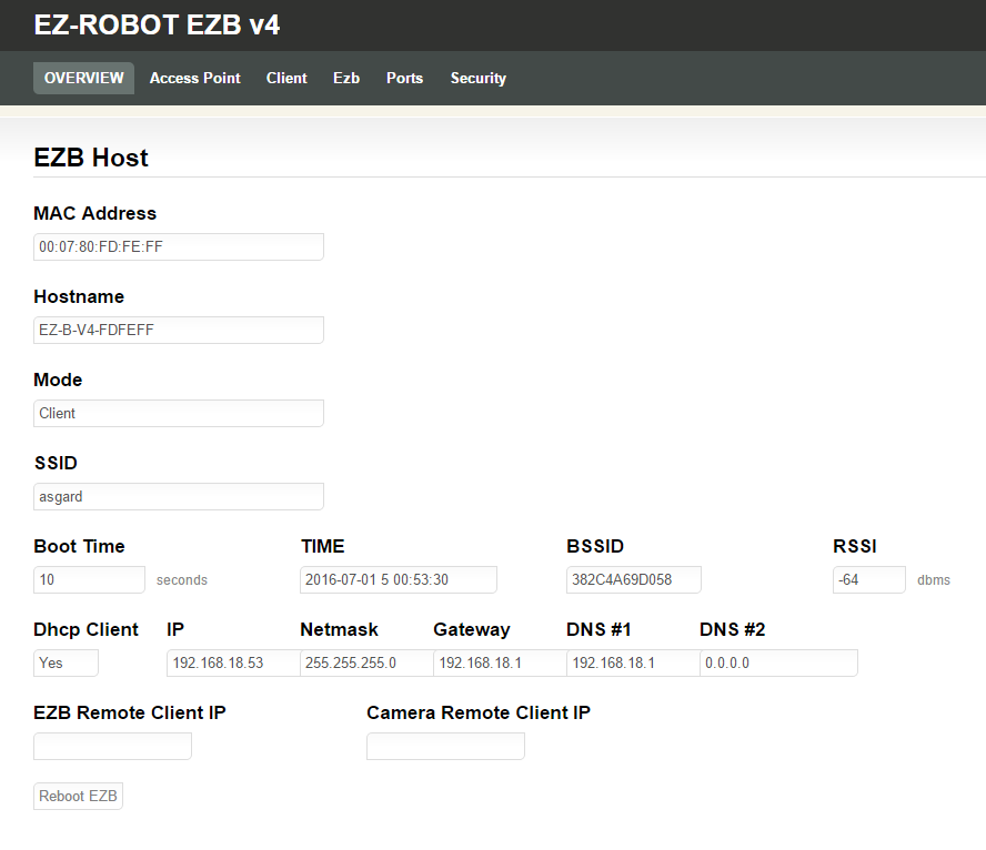
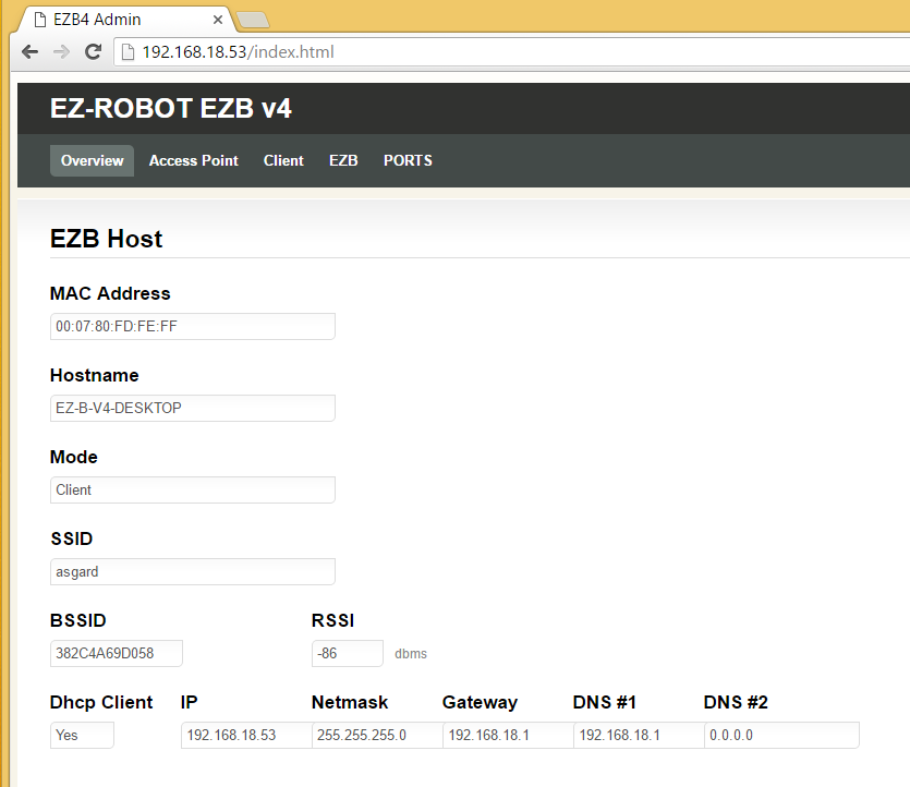
- Initial screen:
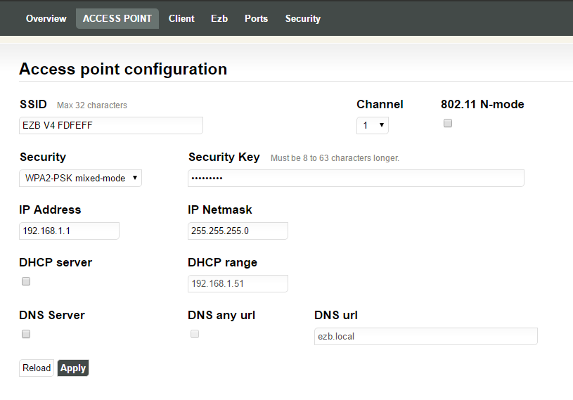
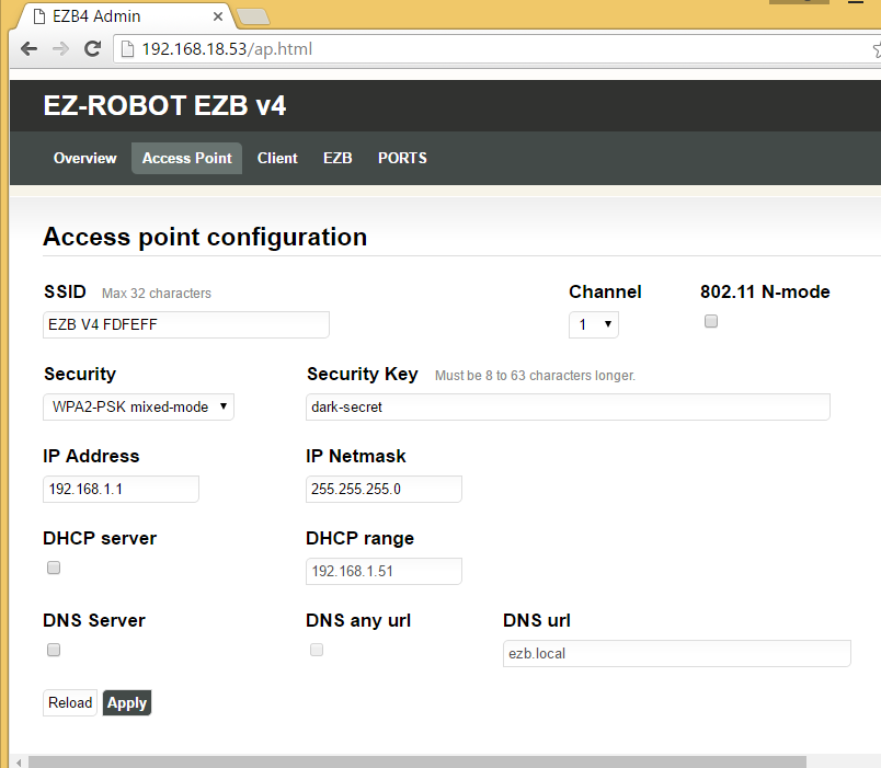
- Access point configuration:
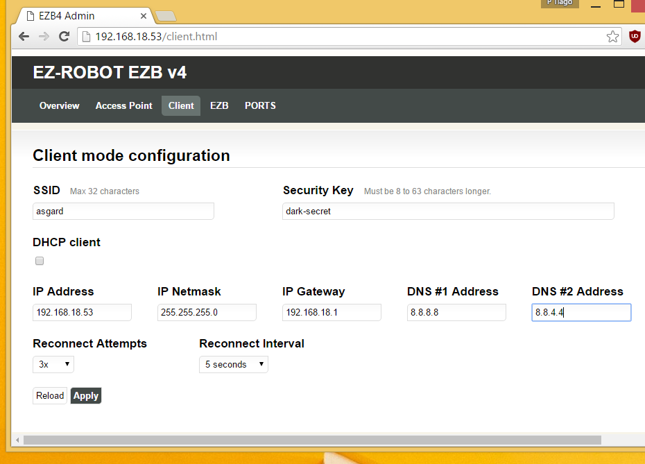
- Client/Station mode configuration:
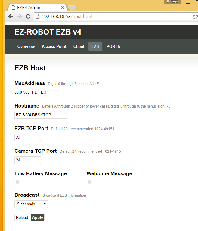
- HOST/EZB configuration:
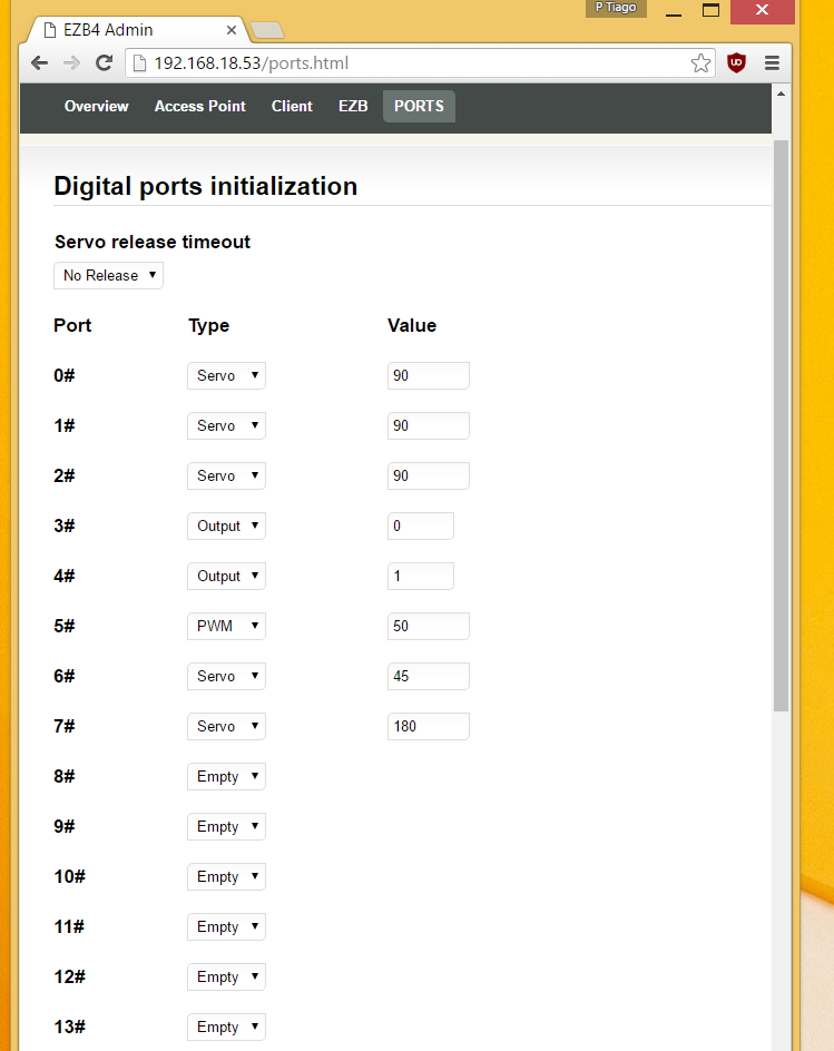
Ports Configuration:
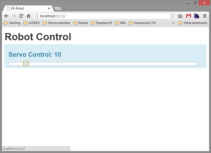
Tools
Working in progress
I will describe in another post the new features.
By ptp
— Last update
Discover more robots

DJ's Omnibot 2000
Omnibot 2000 converted with Synthiam EZ-Builder and EZ-Robot kit: servos, camera, speech, glyph vision, autonomous or...

DJ's Ips (Indoor Positioning System)
Positioning system for ez-robots after years of work and many trials, now heading to manufacturing for scheduled summer...
Pirumpi's Ez-B, I Would Like You To Meet Nodejs
Control EZ-B robots from web and phone using a Node.js module via Synthiam ARC TCP interface with jQueryMobile and...

Awesome job PTP!
I would have shared the broadcast protocol if you still need it
Alan, thank you for the break down. That makes perfect sense.
@DJ
Thanks, regarding the broadcast protocol does include the camera port ? I tried different combinations and no success.
another question for you or Jeremie:
As you know when the PIC32 lockups (i2c or other conditions) the red led is on.
does exist a byte cmd sequence to restart the PIC32 ?
Is the PIC32 MCLR pin available in the PCB ?
there two pins x1 x2, are those clock pins ?
i would like to build a firmware option to reset the PIC32.
If no byte sequence, and the PIC32 MCLR pin is available i can connect to one of the WF121 digital ports.
Ports configuration is a great feature!
Sorry @PTP I didn't see this post until today.
It's actually when the STM32 on main board locks up that the red LED stays lit.
Sorry I don't know but @DJ might.
Yes, MCLR is broken out to the first pin of the programming header
X1 and X2 are "extra" pins made available from the STM32. There were broken out for future projects but haven't been utilized yet.
The PIC32 is the wifi module that you are programming, and it does not lock up with the red led.
The red led is connected to the bottom board STM32. When the red led comes on from incorrect i2c communication, there is no software recovery. You will need to reset the power on the stm32, as it cannot be done via software.
As for the ezb broadcast, here is the protocol...
Transmit those packets every 3-6 seconds to 255.255.255.255 (0xffffffff). For udp broadcast, be sure to use socket option SO_BROADCAST
@DJ, Jeremie: Thanks for coming back to the thread, i know you have a lot in your plates.
I wrote it incorrectly (PIC32) i wanted to write ARM
@Jeremie:
Arm board:
The NRST pin (7) is not accessible, 1)i see a capacitor C13 connected to GND and NRST 2)i presume the NRST is connected to the VCC, but i can't guess if there is a resistor between VCC and NRST ?
If there is a resistor, i can safely pull down to do a reset. The idea is to restart the ARM when is in lock mode.