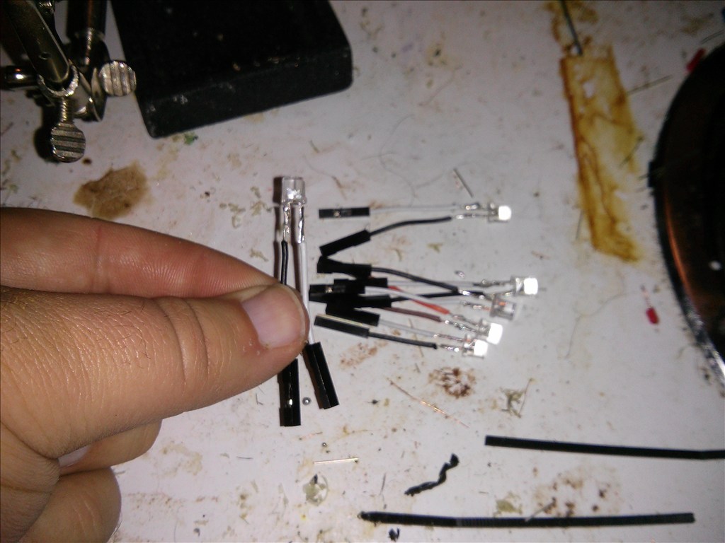
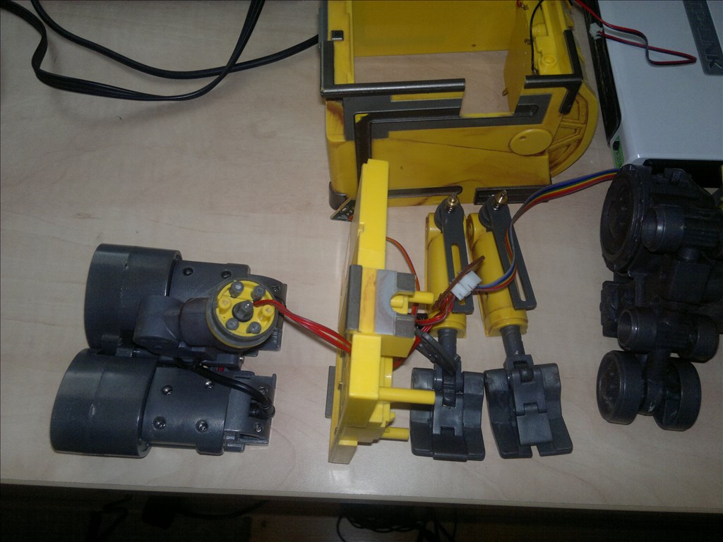
During my last setup with a h bridge I was frustrated and wish I could see if the ports were active at the time they were triggered but I don't have enough hands to hold a meter , not short something out and still toggle ports to troubleshoot my setup. So I wanted to share this idea. All you need is a servo connector or jumper cables. Cut off the red wire. Connect a left long lead ( pos) to the white and short lead to ground Ta DA! Easy

By jstarne1
— Last update
Other robots from Synthiam community
Moviemaker's Sunshine Is Back In Town
Well after many months of waiting and being sick, SUNSHINE is back in town! She stands four and a half feet, with her...
Donesvarc's Wall-E From Czech Republic
The first real but not main reason for Wall-E construction was that my son loves movie Wall-E and the second one was...
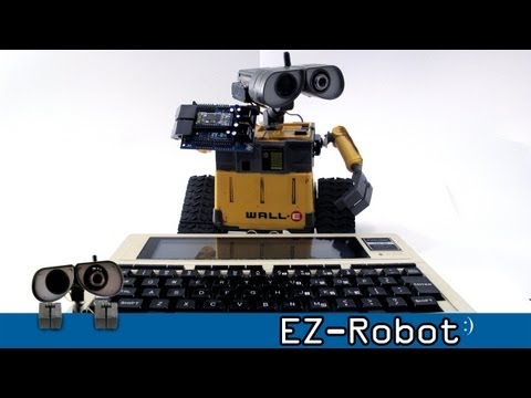
DJ's Trs-80 Model 100 Controlled Wall-E
<div class="embed-responsive embed-responsive-16by9"><iframe class="embed-responsive-item"...

https://www.youtube.com/watch?v=XzhVm3WWyy0&feature=youtube_gdata_player
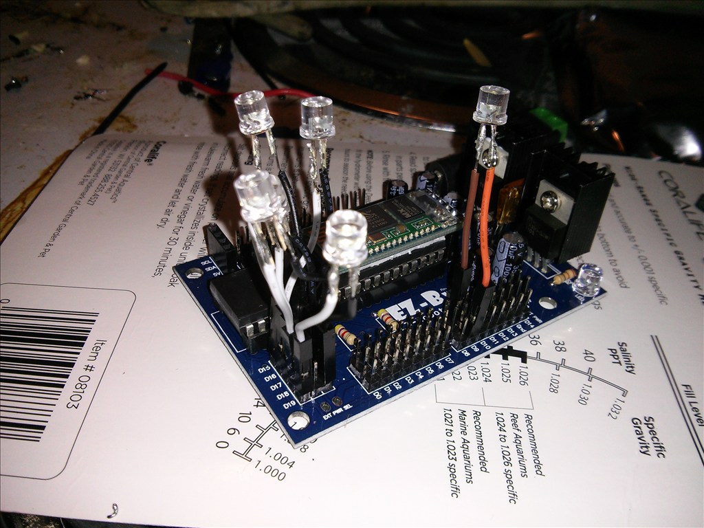
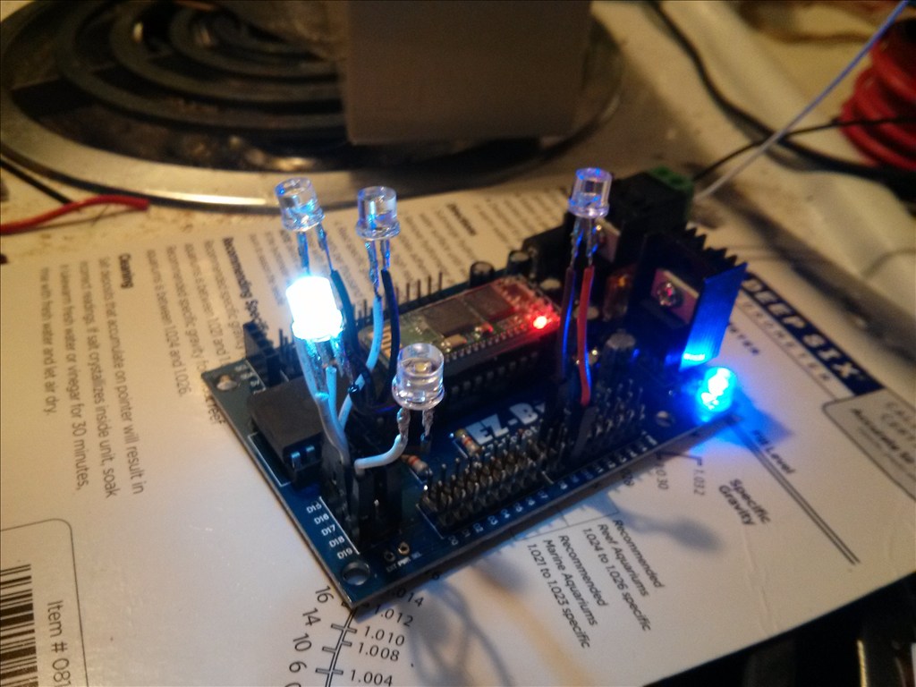
Thank you Josh! for your generosity . The LEDS use very little power for testing UNLIKE servos, like I am using. :)
Wednesday, 20 March 2013
Good Morning Jeff Starnes, aka jStarn1 !
Also, Your long list of projects is MOST Impressive !
If You would like a FREE Roomba to Hack, please call me ?
I would enjoy Chatting with you about EZ-B's !
Thank You & Best Wishes From Phoenix,
DougPope@cox.net, 602-246-1246(H)
P.S. I am still trying to purchase a Full Set of OSMO's, Both 400 & 500 Series for our local Washington High School Robotics Club ?
This is a great idea Josh!
Great idea Josh. Seeing the light come on is nice and makes it easy to troubleshoot. I should make me up a rig like that. What I usually do not all to free up my hand is too cut the female end off of a servo extension. Then I use an alligator clip jumpers to attach my meter. That is nice because I can see exactly what voltage I am getting. Sometimes it's important to know how much voltage you have and if it is positive or negative.
By the way did you ever get your H Bridge working?
A few H-BRIDGES comes with leds on board, 2 leds per channel MOSTLY L298 types But still a good idea JOSH ,i havemade test lights like that to check my arduino and basic stamp boards
Also anyone needs some leds i have more then 100 of them and free
A thumbs up Josh Nice idea !
I'm considering making a whole board that plugs into the ezb and can test them all at once. Thanks guys for the compliments. I try to do things that are simple enough to repeat with a few pictures. ;)
I made at work a pcb testers that checks all outputs on a board after it get stuffed called "pins of nails tester",but for EZB would be to hard and some testers i added vacuum.
BUT how i check mine very easy is using a breadboard, a meter and a few leds ,its simple easy and fast
I see you didnt use a resistor to limit the current,what will happen it may burn out the outputs.
ON 5 volts you need 470 ohm to 510 ohms,some do use 330 ohms but not really good led gets very bright and not needed ,its only to test the output.
not light up the whole house .LOL
Why would anyone need a resistor? Just to bring 5v down to 3 volt?
thats not the problem resistor is not for voltage its for current,simple ohms LAW even at 3 volts you run the circuit at you still need a resistor to LIMIT the current
Ohms law.. OK I'm not going there. It works for me and they draw under 25ma max for ezb digital port.
Hey Doug , I would love to have a room a that would be awesome! Of course I would EZ robotify it ;). I'll message ya tommorow its time for bed here.
If it works for great.but still its not the correct way to do it,look at the circuits on the internet is shows to use a resistor,second leds mostly made for 10 ma and you arer driving at 25 ma more then twice the current so its bad for for the led too.
this is what dougpope ask too Your LED-Jumpers idea is GREAT ! What limits the LED Current to 5 or 10 Milliamps ?
Ohms law indicates - Amps is limited by the resistance of the circuit at a given voltage. For current to increase so would voltage input and its works in reverse as well. Lower the voltage input and current will lower as the resistance of the circuit remains the same. There's no reason for a resistor in this device.... In this case a led does not draw more than the current rating of ezb digital outputs. Lets not make a simple and easy to use tutorial get complicated for no good reason for a new user that does not understand ohms law and its uses. okie dokie
ok,just trying to help you from a burned led, when driving a led at more then the correct current it will burn out I only bought it up because of dougpope comment and his is right about it too. :)
JOSH hope to see some photos of your designs to check all the pins on the EZB ,could help others thats not much into electronics and would make it easy for testing the outputs too.
Oh no I never got that h bridge to reverse so I tossed it . I'm moving this week so I have not done much work with all the errands.
WOW thats wierd JOSH mine works great when i hook it up.
By the way that h bridge was faulty , the right side could not reverse but everything else worked so I tossed it. I'm going to buy some directly from ez robot it feels like money better spent ;)