


Day 1 (4th August 2015)
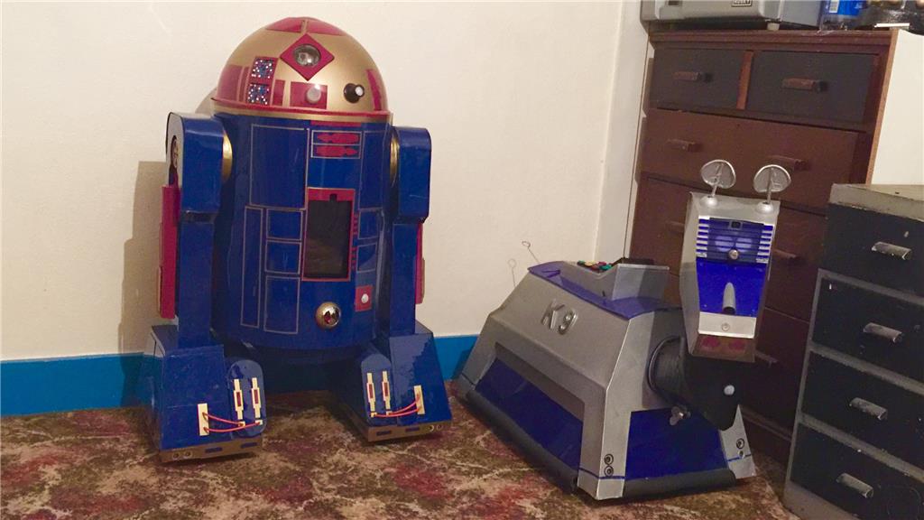
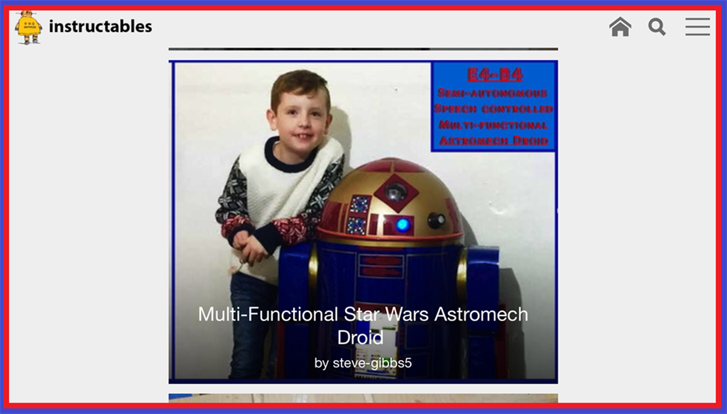
So after throwing around a few ideas for a new project to sink my teeth in to, I decided to go ahead and do my own version of an Astromech Droid, rather an Astromech "Smartdroid". With K-9 being one of my all time favourite on-screen robots, R2-D2 was (and still is) just as much of an all time favourite of mine so building one of my own droids is a logical step for me. As my other robot showcases where posted when the majority of the work was done, this will be a build diary of sorts, with updates throughout the build.
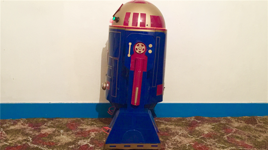
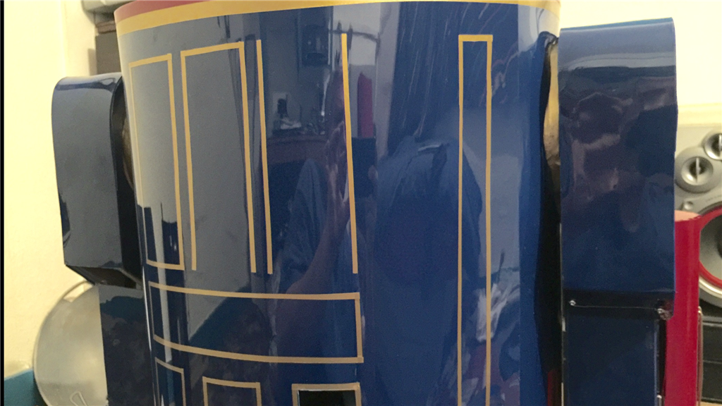
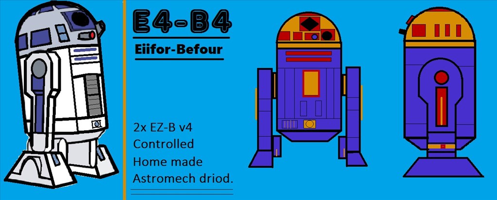
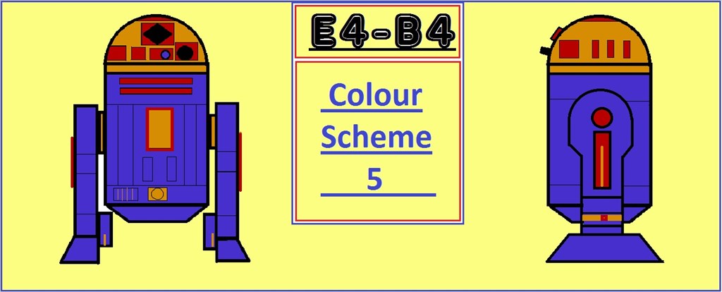
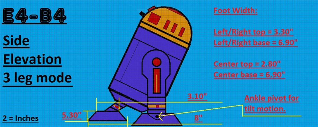
So wanting to get back to building, I had a few ideas floating around for my next BIG project and the thought about doing an R2 style robot came up a few times in the past (the blueprints I drew up that I've posted are 3 years old and was for an R/C version), and after encountering a few design issues for a large custom robot (which I will get back to one day), it was @Robot56's fantastic Astromech Droid project that was the final push for me to decide what direction I should go. There are so many great scale replica Astromech builds around that people have done, but much like my K-9 2.0 build, I want to stay away from doing an exact prop replica build and do a custom build with custom paint job (as seen in the blueprints) while still keeping with the overall original design.
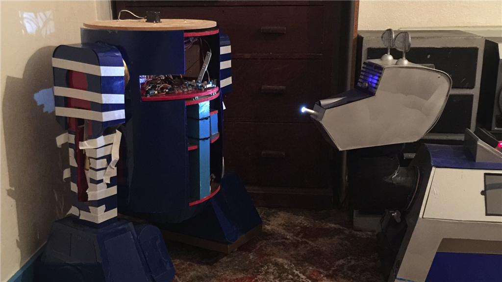
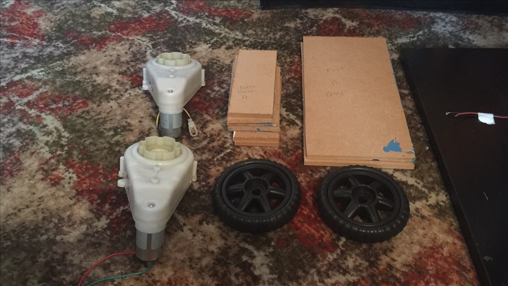
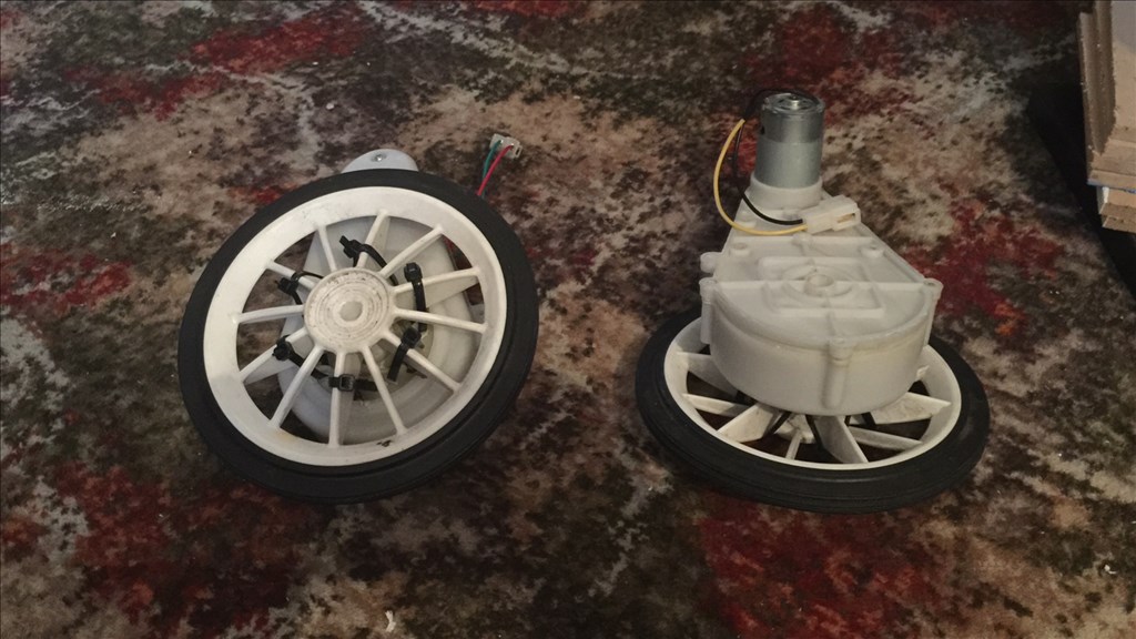
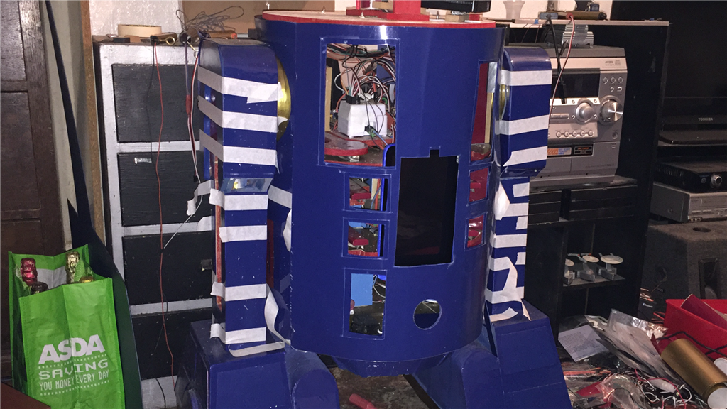
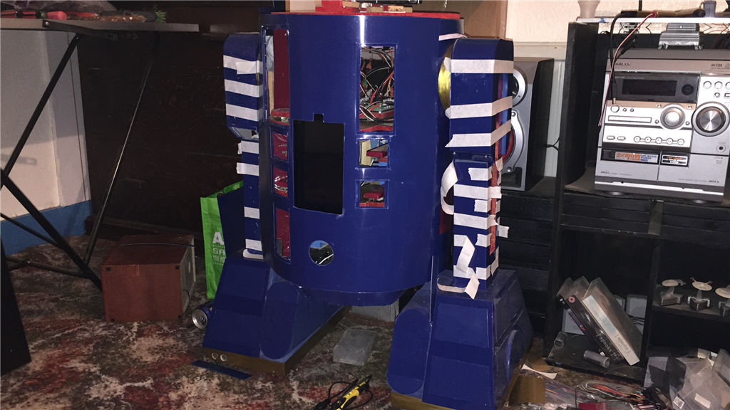
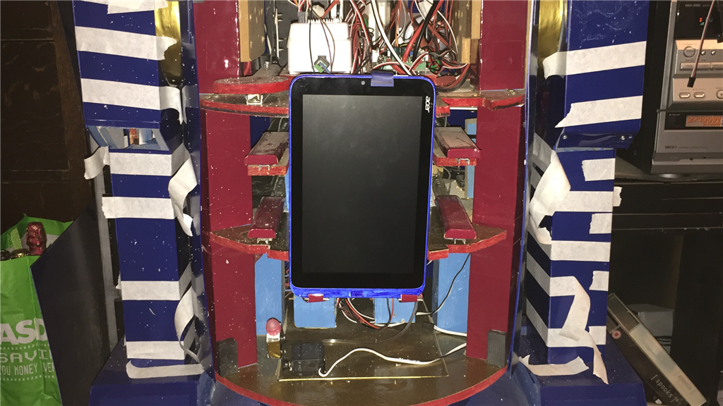
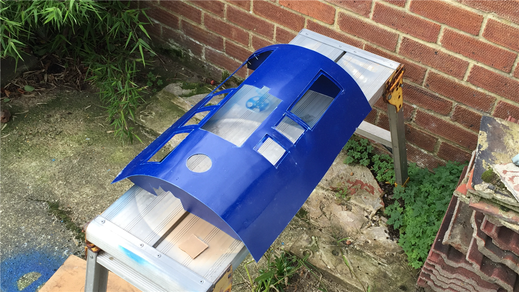
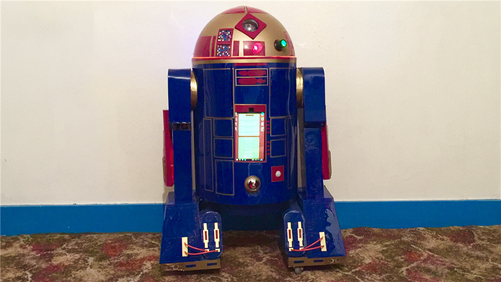
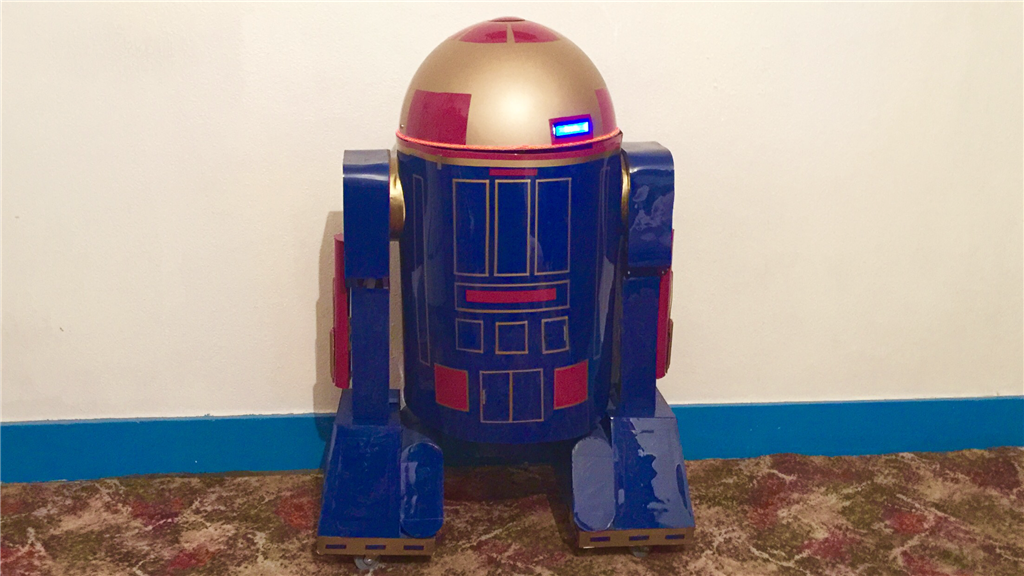
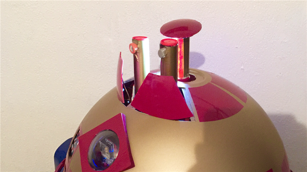
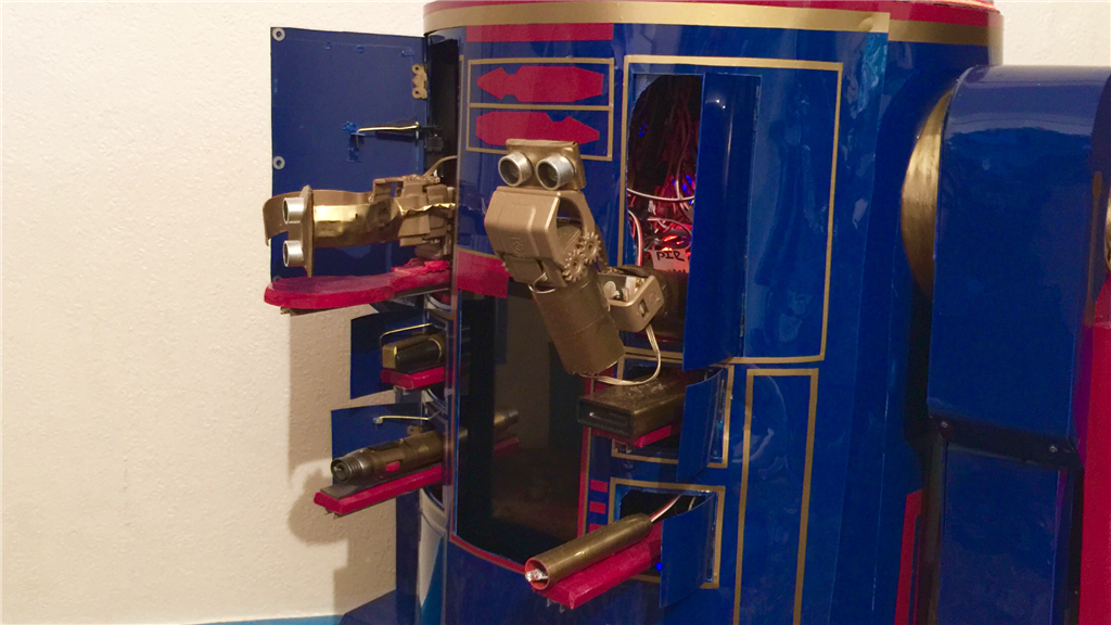
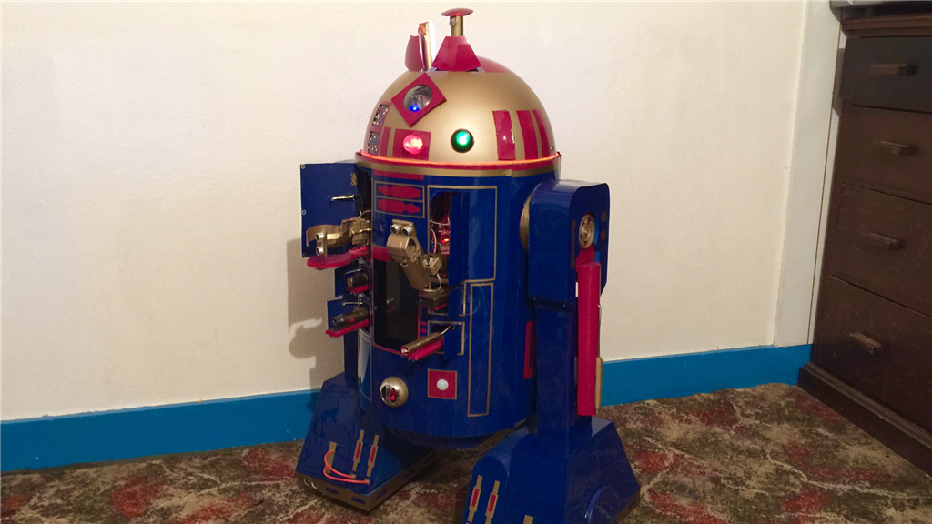
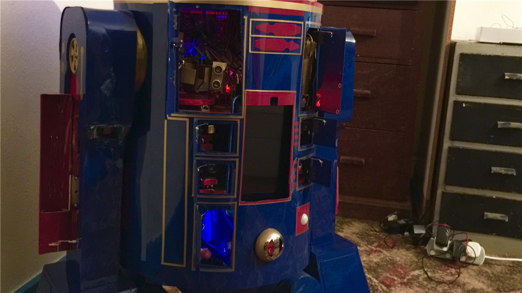
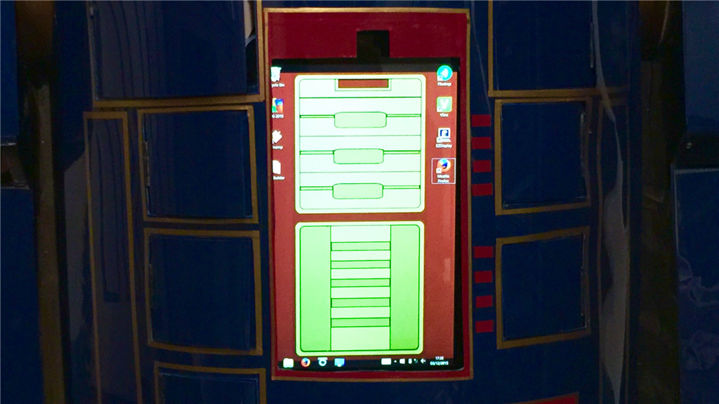
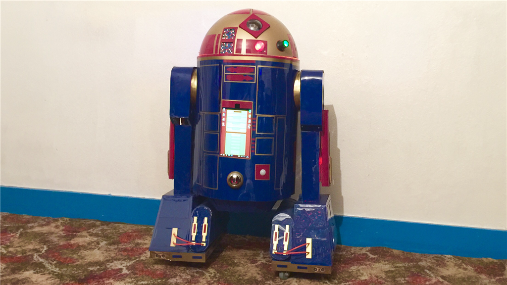
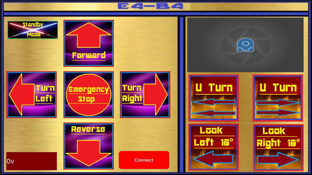
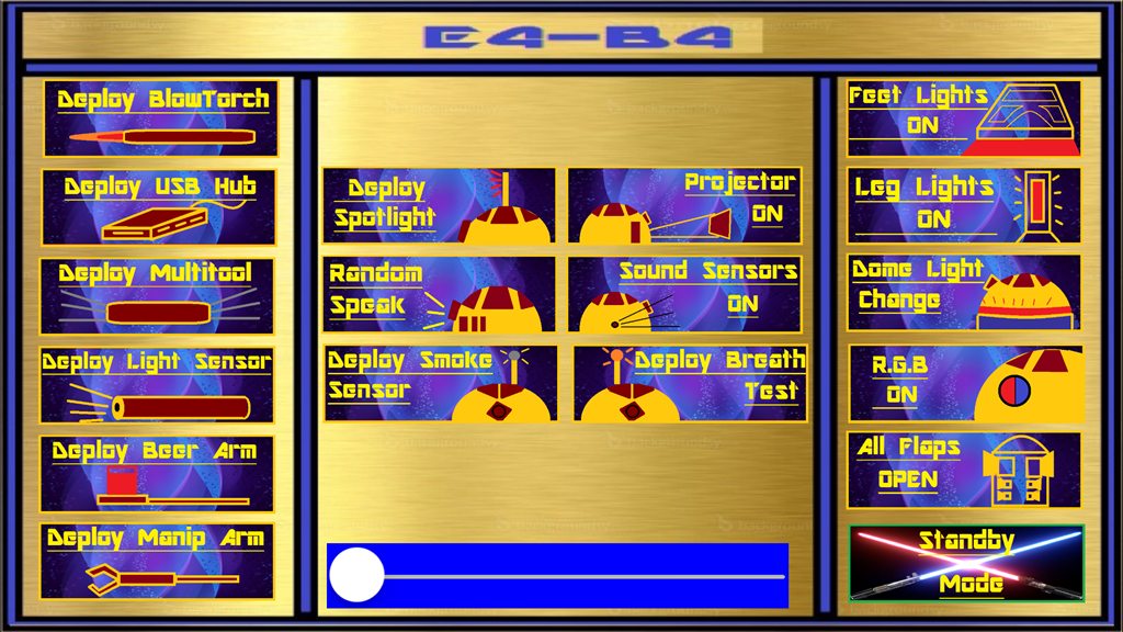
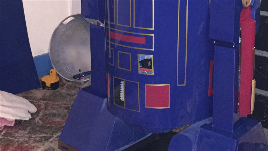
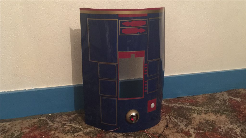
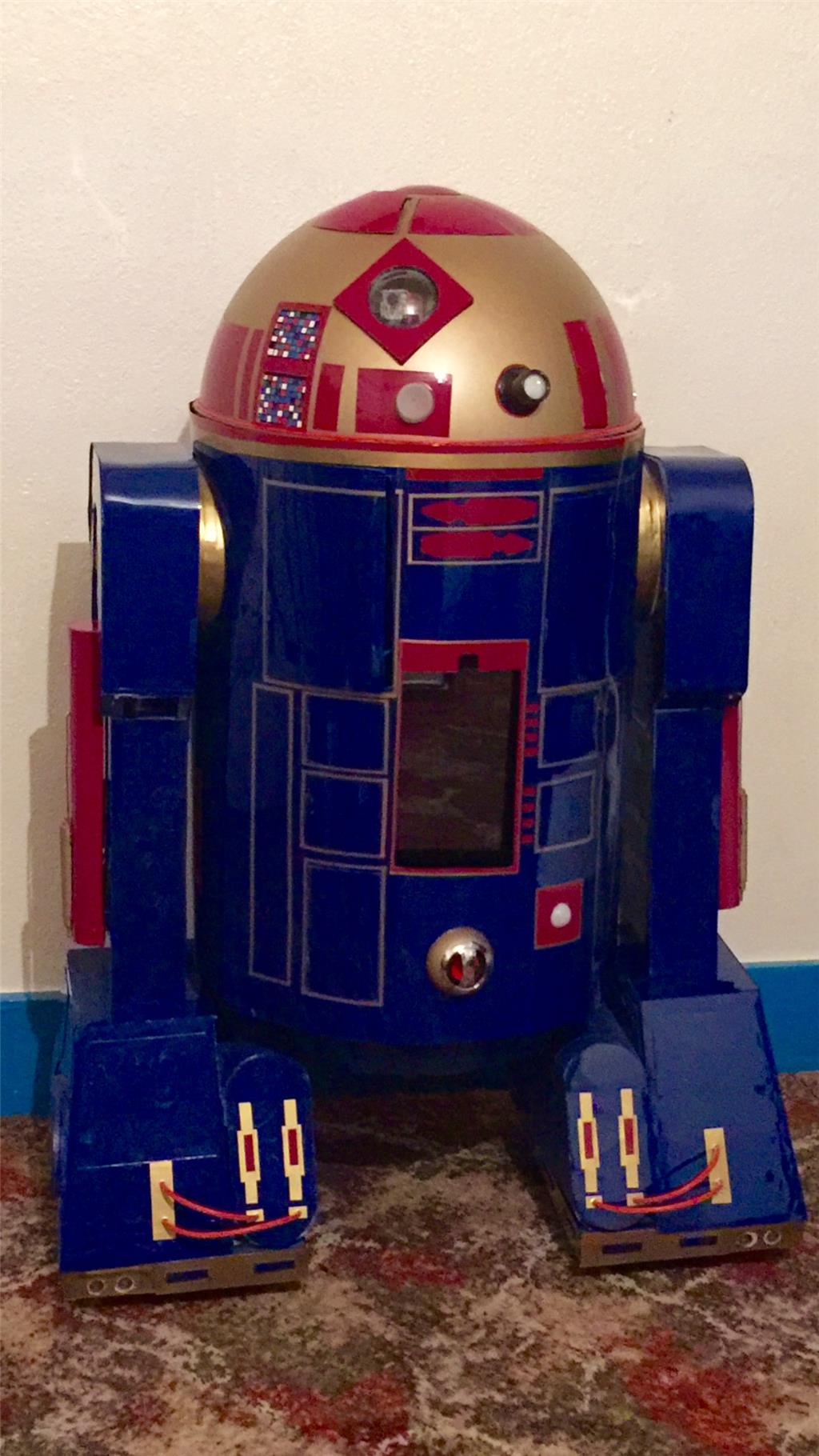
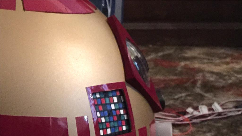
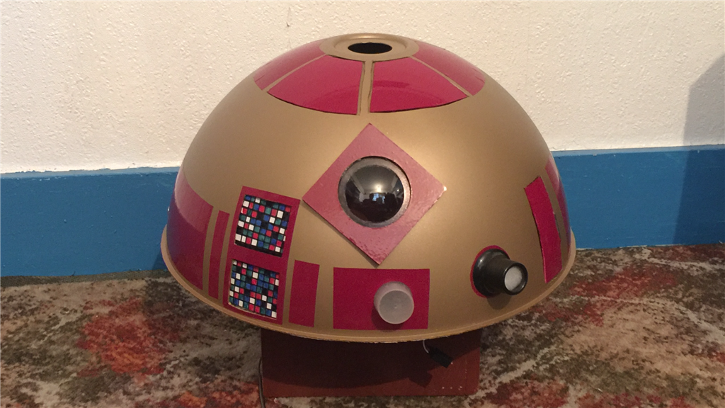
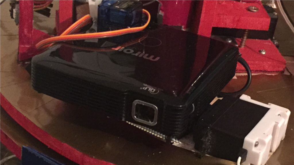
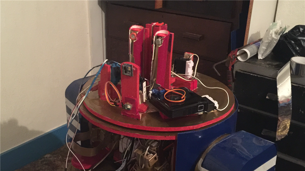
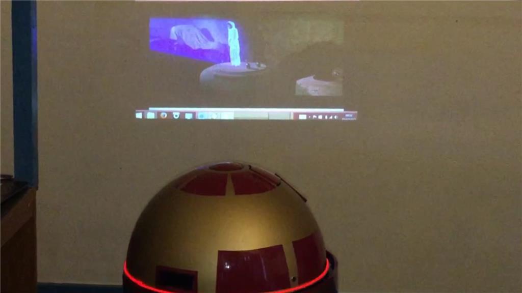
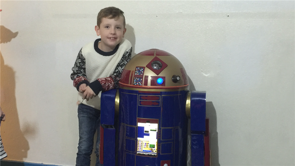
So what's with the name E4-B4 (Eiifor-Befour)? Well its kinda based on the EZ-B 4, of which this little'ish guy will have two of them. One master v4 to control motor controllers, ping sensors, v4 soundboard, camera and sensors, while the 2nd slave v4 will be used for all of the servos used as well as additional sensors. E4 will be mainly built using MDF with a plastic covering, and movement will be powered by 12v 30 watt gearbox/motors for the drive system. The "burtt acoustic signaller" and system ventilation vents on R2-D2's chest area (the two silver square'ish panels) will be replaced on E4 with a tablet PC, and the Optical Holographic Projector in R2's head will be something similar to what E4 will have, using a portable projector like the Aiptek or the Pico Genie, so no holograms... yet.
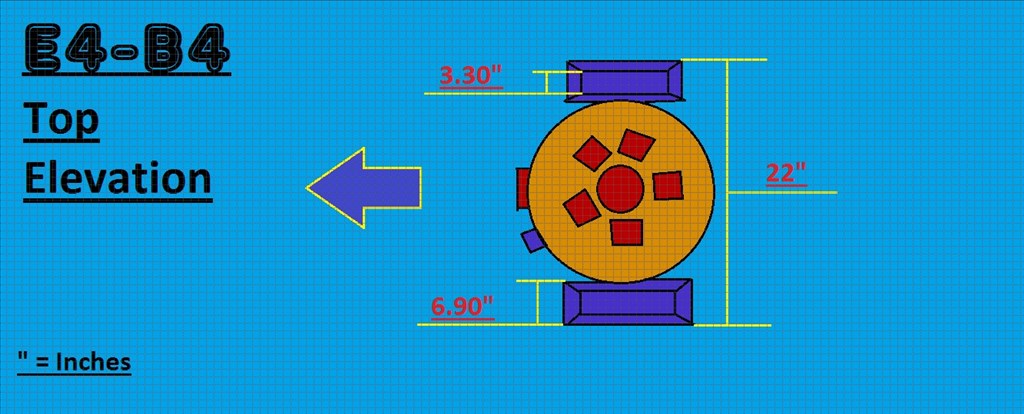
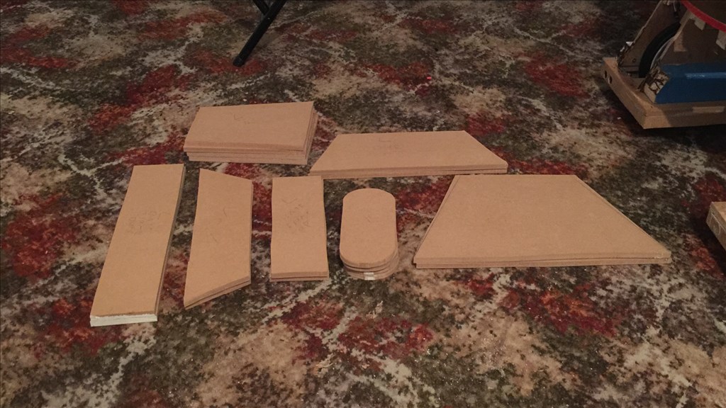
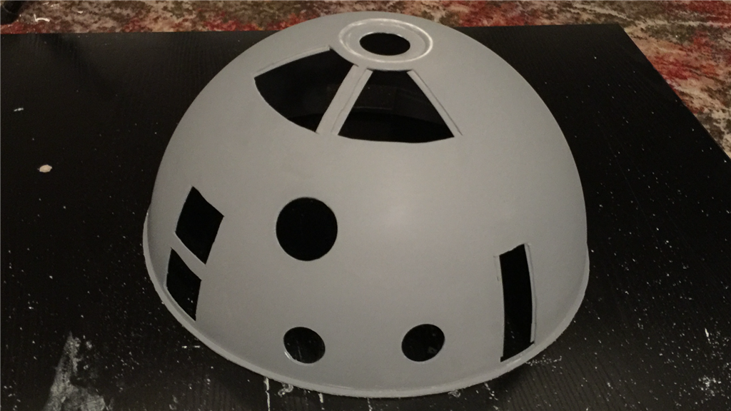
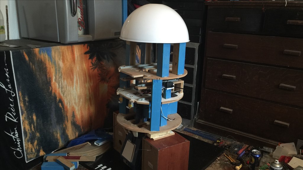
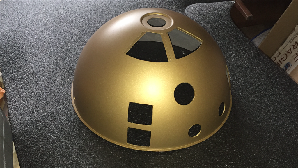
The dimensions will be slightly smaller than the original prob, but not by much so E4 will be plenty big enough. I'm intending to fit a few useful tools that he will be able to deploy, and of course have the fully rotating head which will have all kinds of bells and whistles. I have some of the MDF sheets and 2x4 wood lengths for the frame already, and the motors and head dome (lampshade) should be with me sometime this week, so it will be power tools at the ready. I'm in no rush to finish this project, but I am aiming to have E4-B4 pretty much finished by this December.
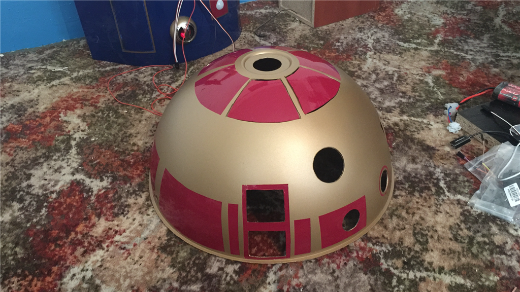
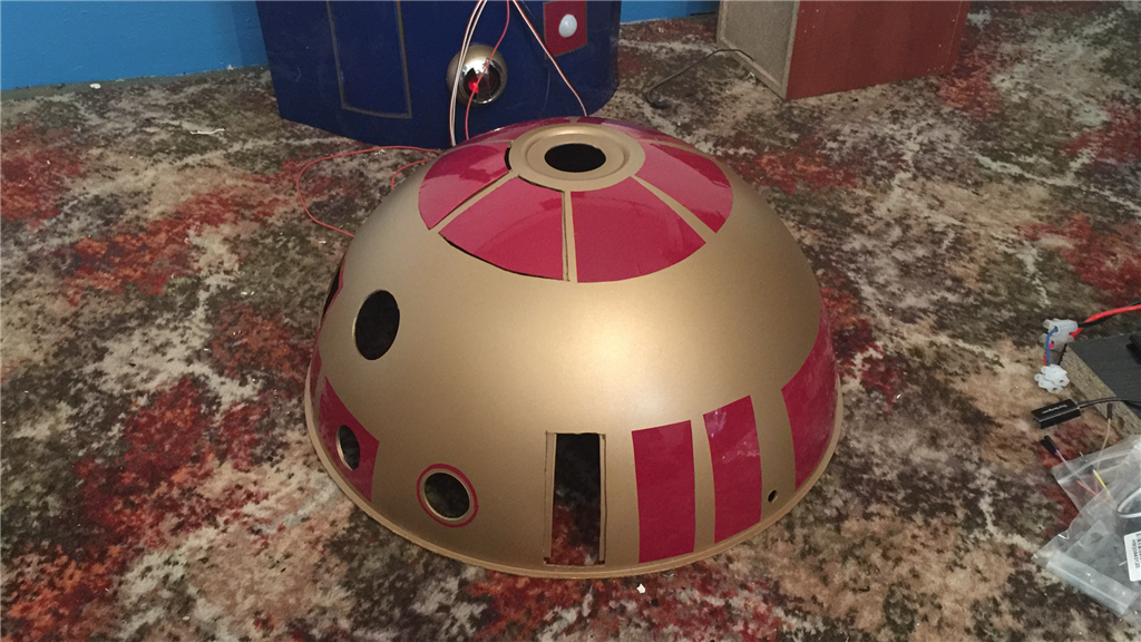
I will posting lots of photos and few videos throughout the build process, so I hope anyone reading will find this build dairy interesting and enjoyable. And as always, I'd love to hear your thoughts and suggestions (especially on the colour scheme). Anyway thanks for reading, and let the build begin...
Steve.
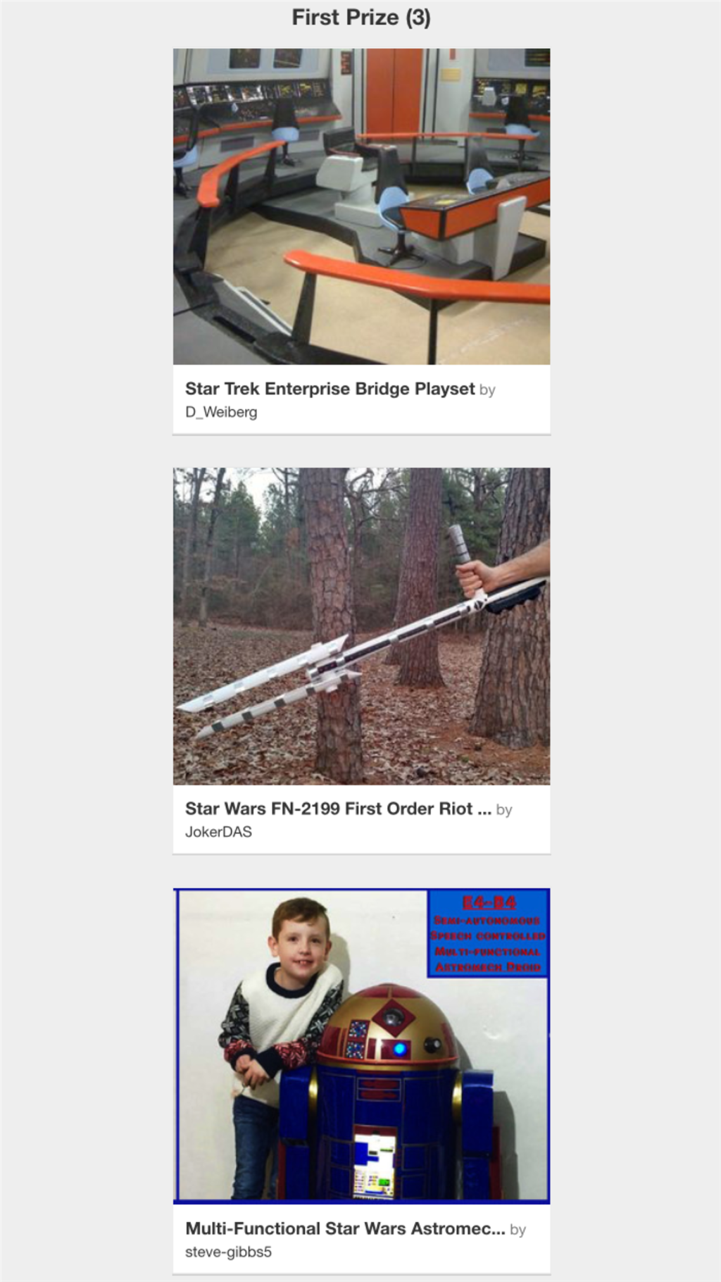
Discover more robots
Peterfrisch's It's Yellow, It's Boxy, It's .... No Wall-E...
Herg62123's Omnibot 5402 Project - Code Name: Minion 8

@robot56.
Thanks dude. Yeah, I got lucky with our temperamental UK weather yesterday, so I managed to get a lot of cutting done. It should be nice today as well, so I should be able to get a lot more done this afternoon.
Day 7 (11th August 2015)
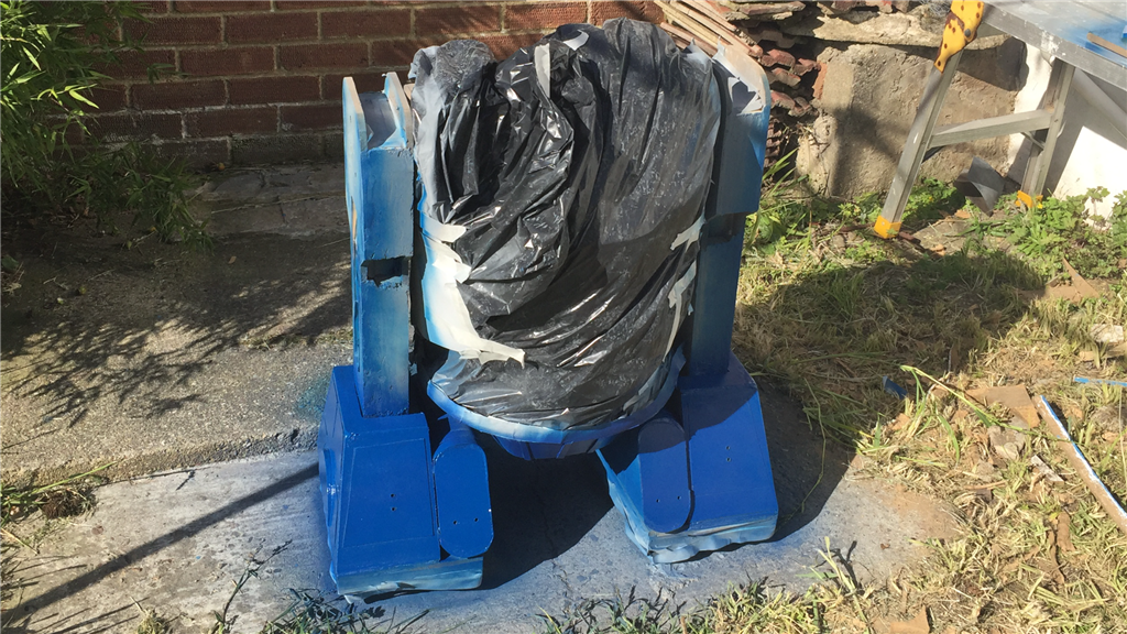
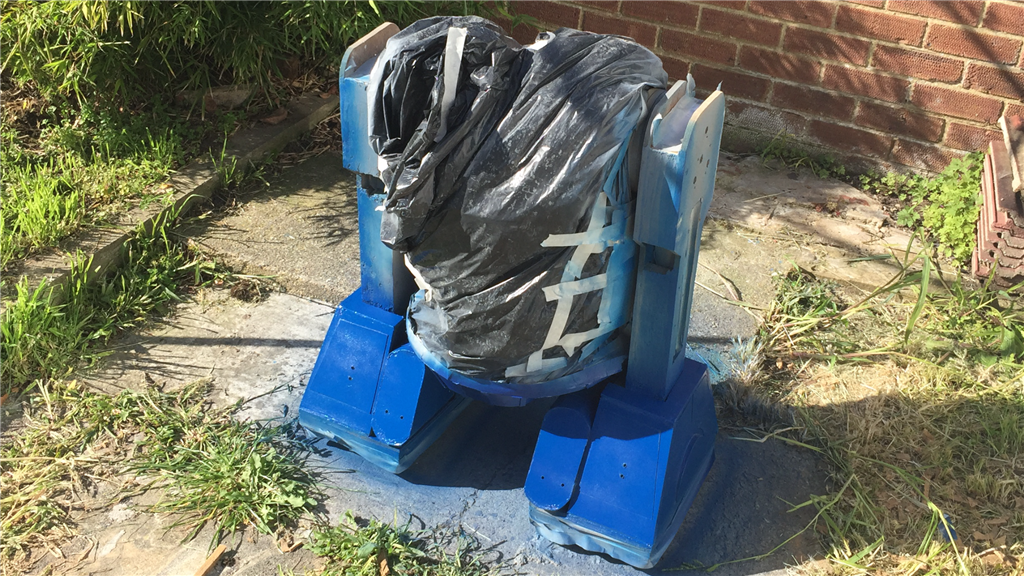
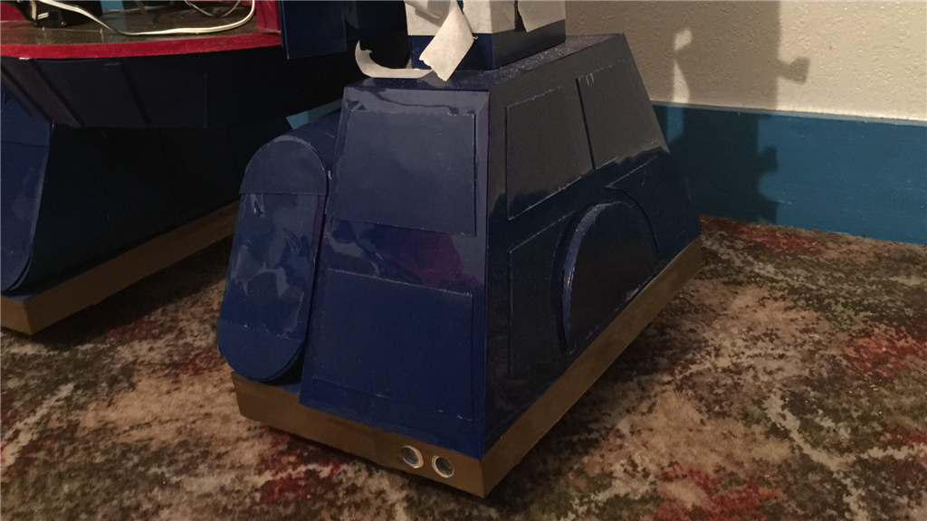
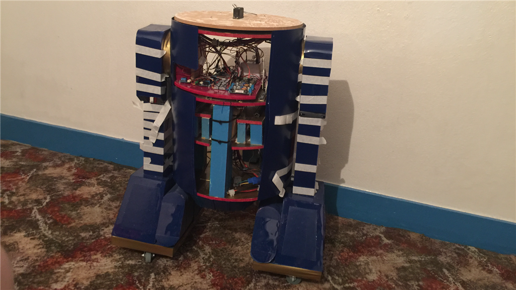
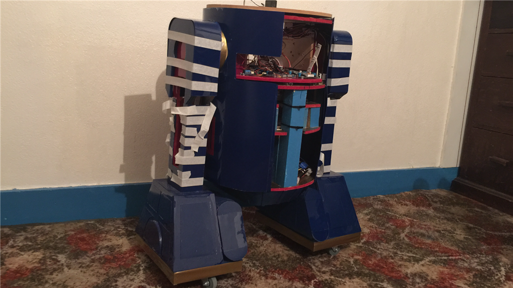
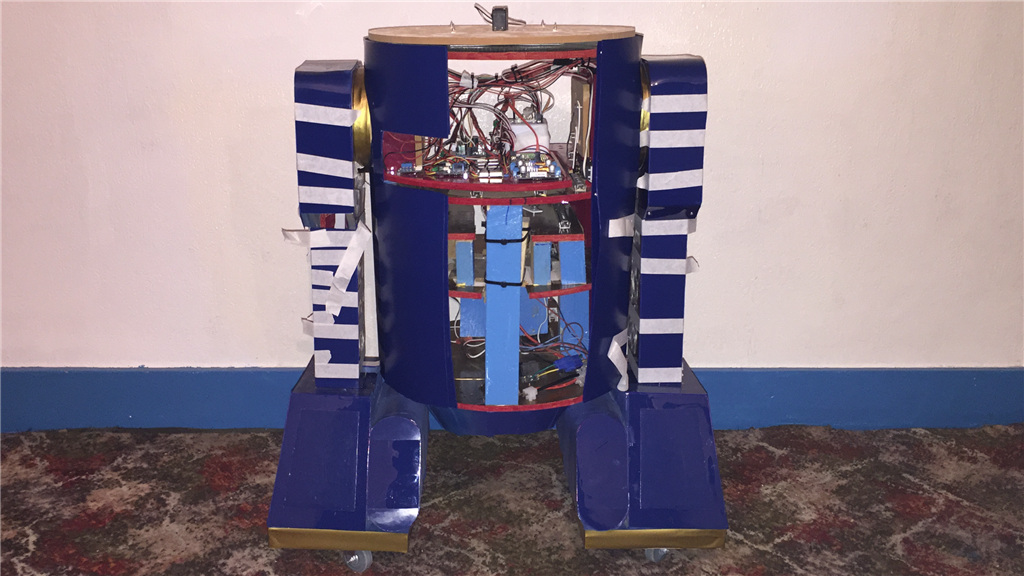
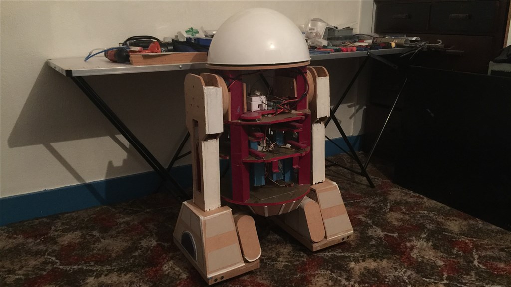
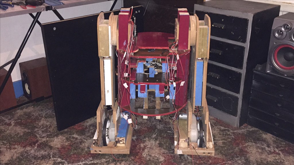
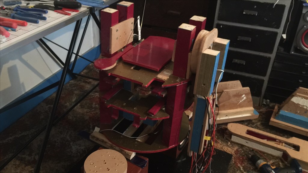
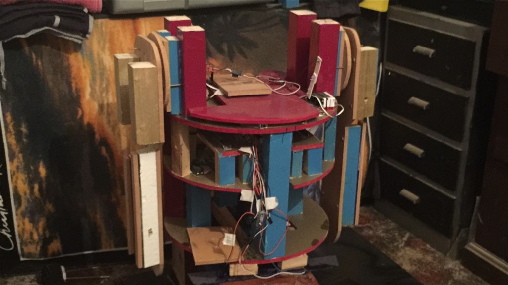
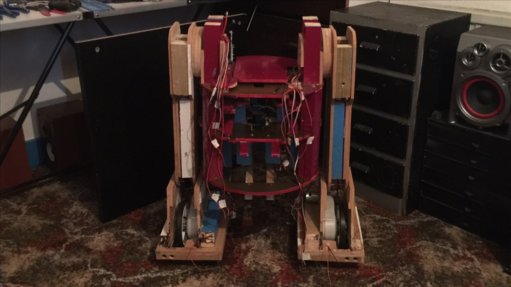
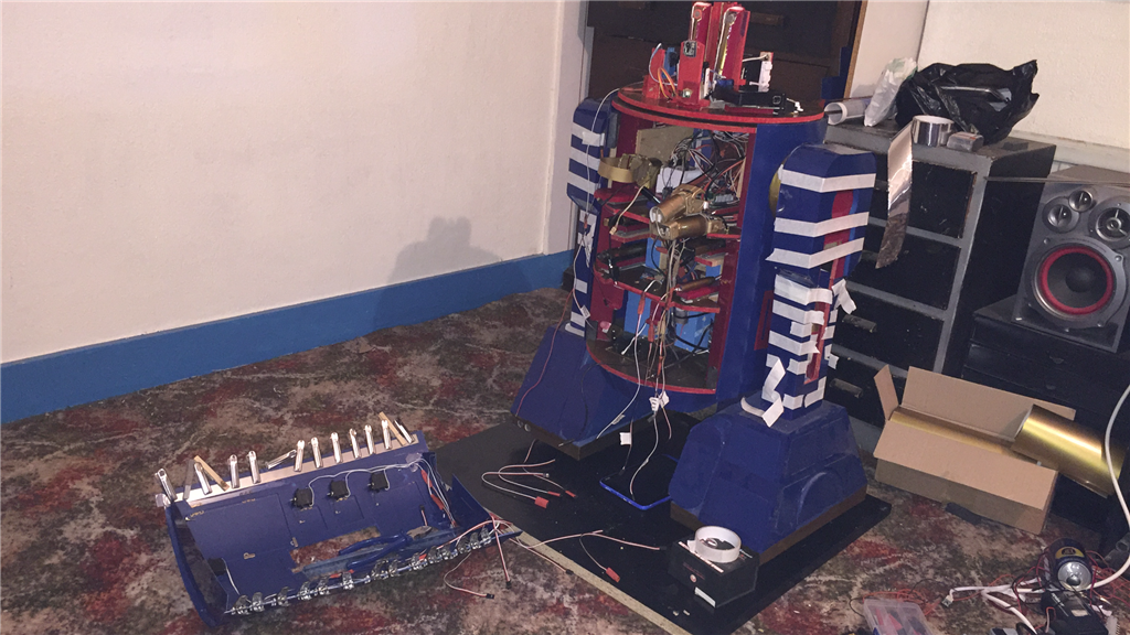
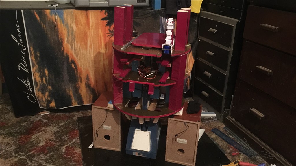
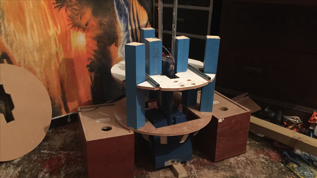
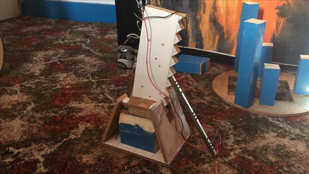
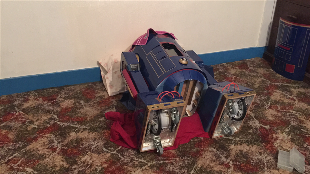
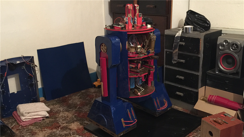
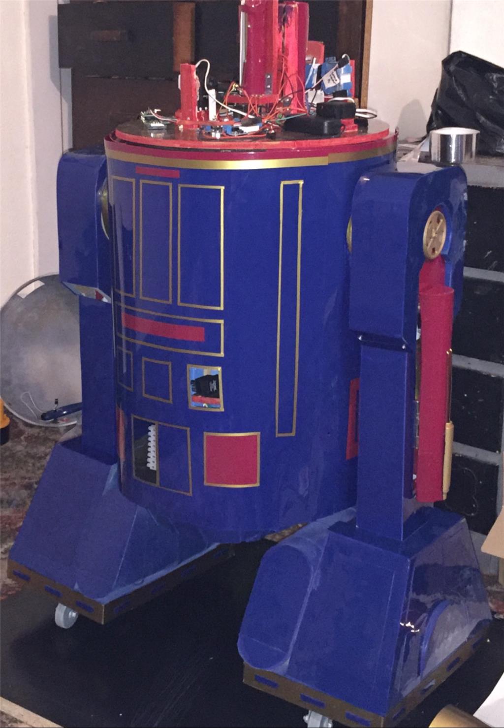
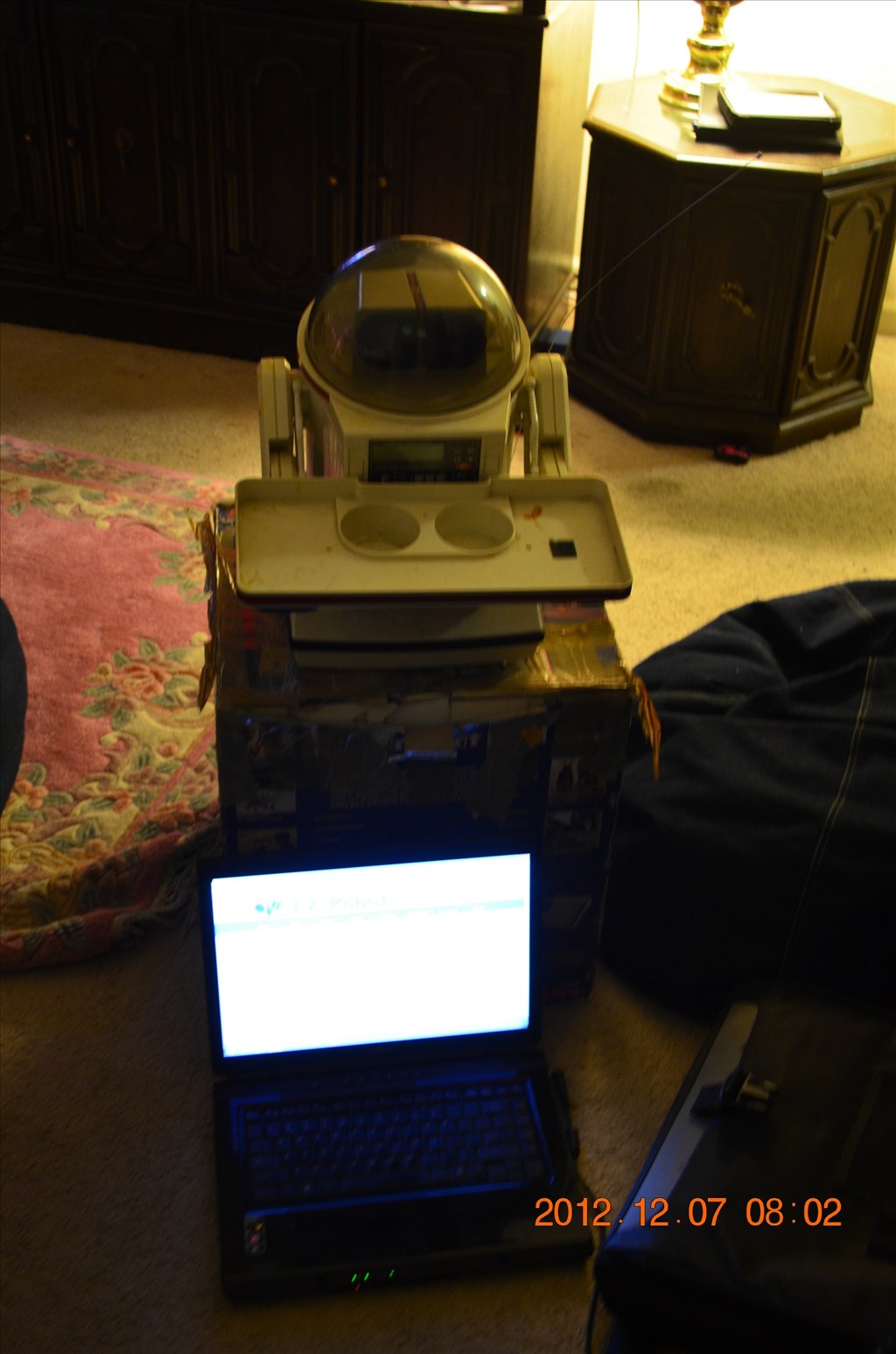
Well, I managed to get a bit further into the build over the past couple of days, and the base is pretty much done. So here is what I've completed so far.
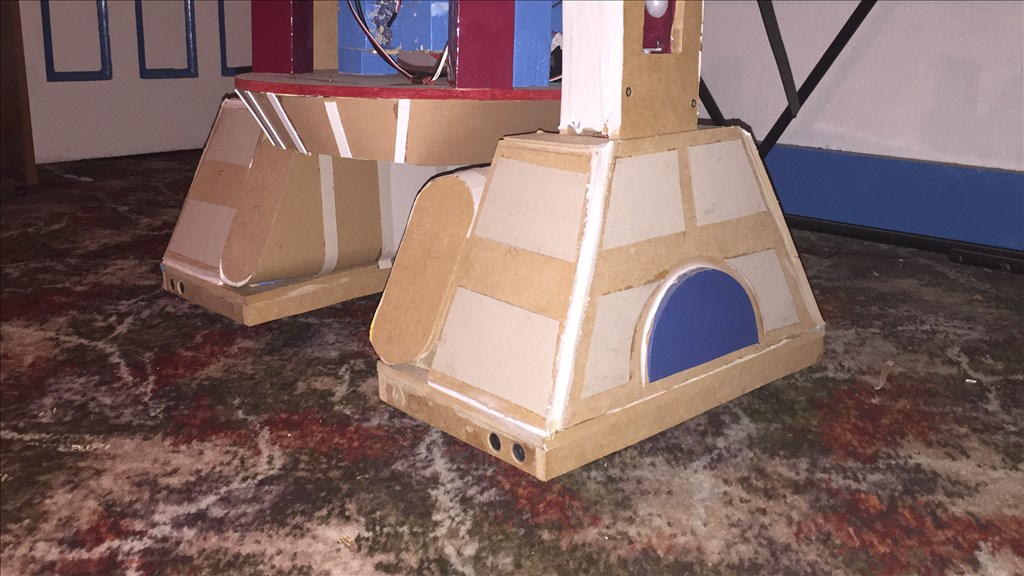
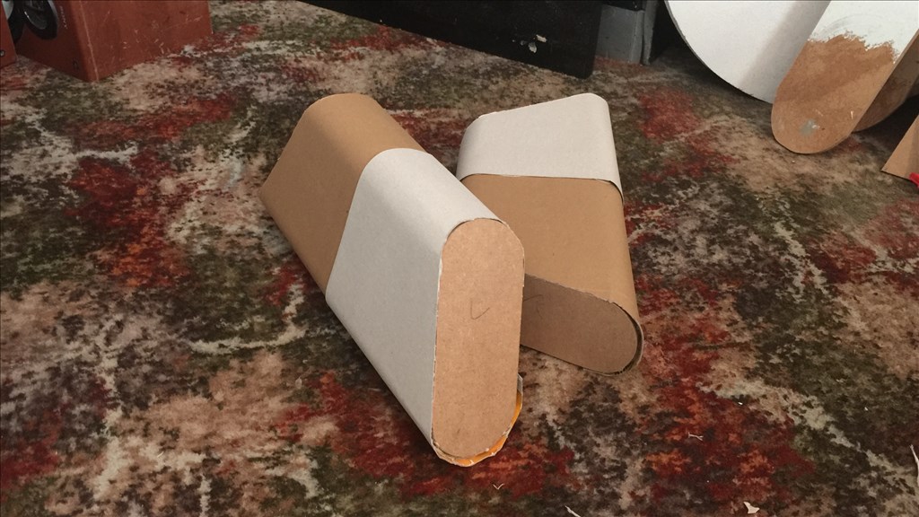
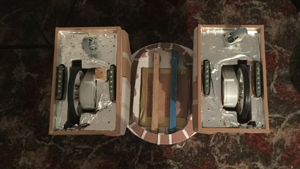
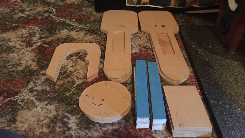
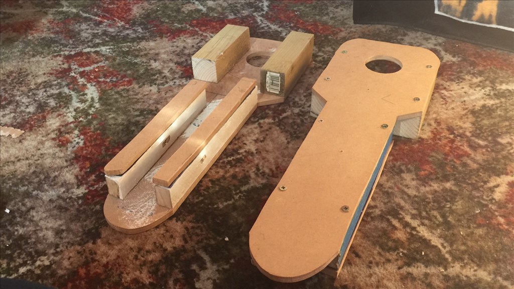
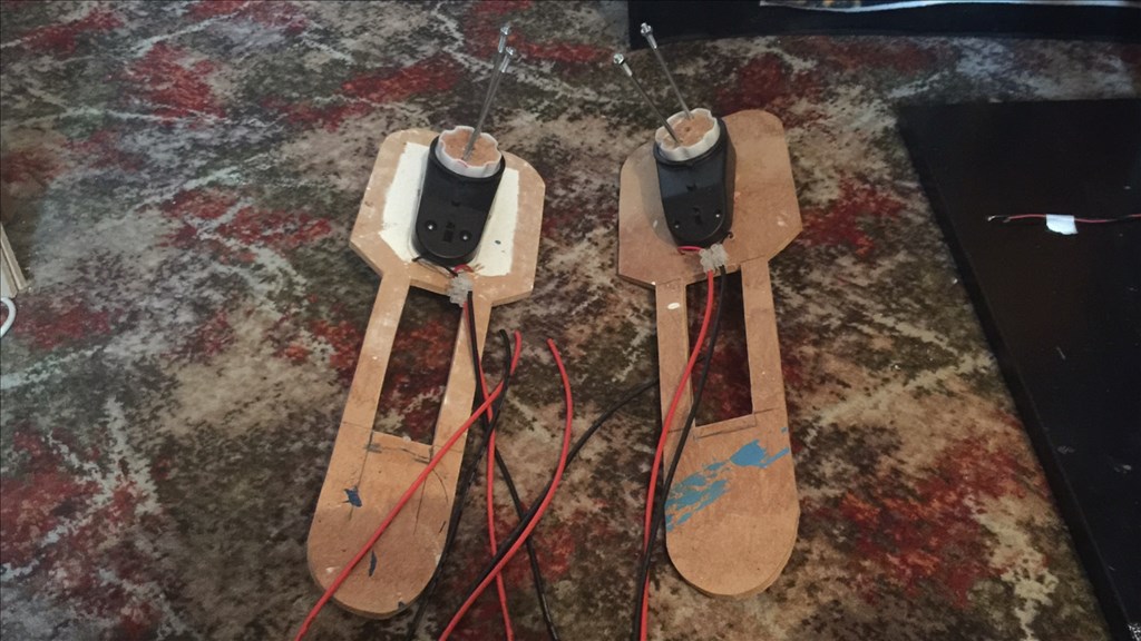
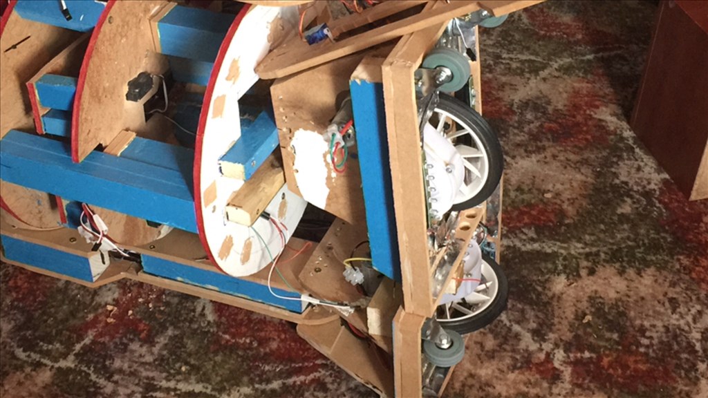
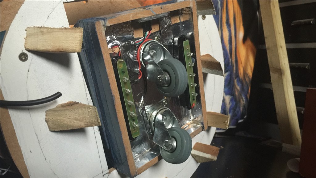
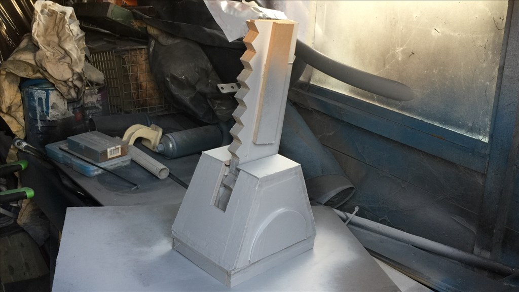
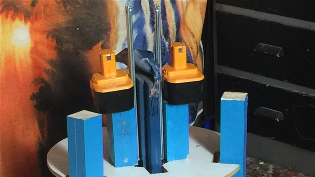
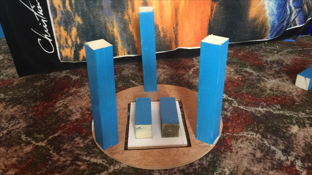
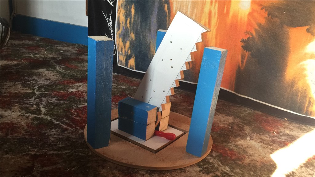
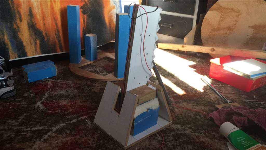
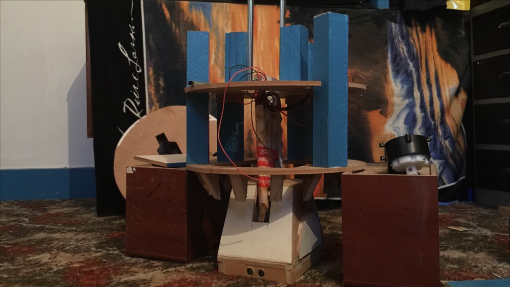
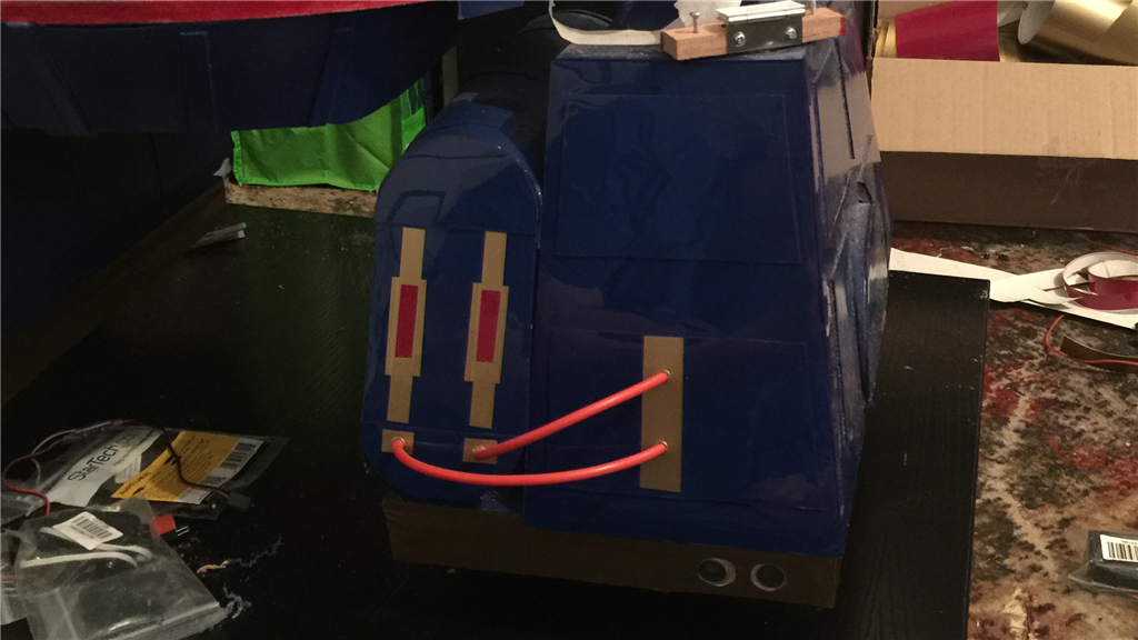
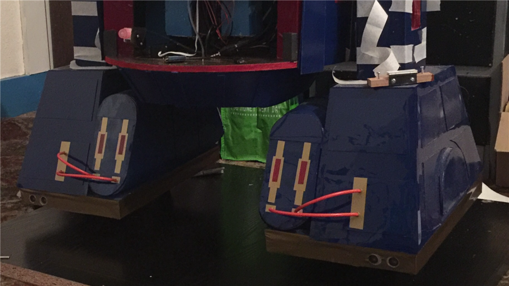
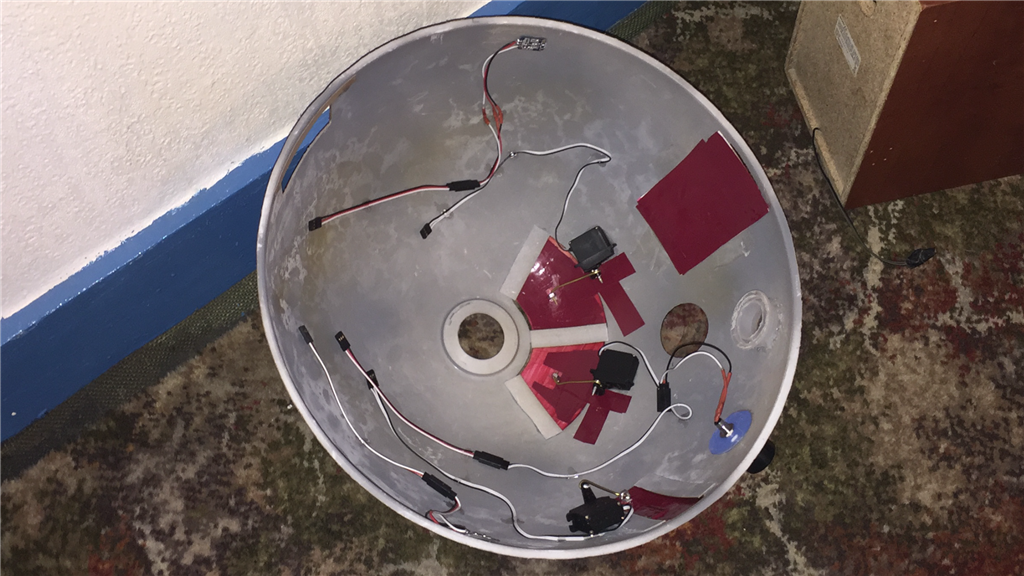
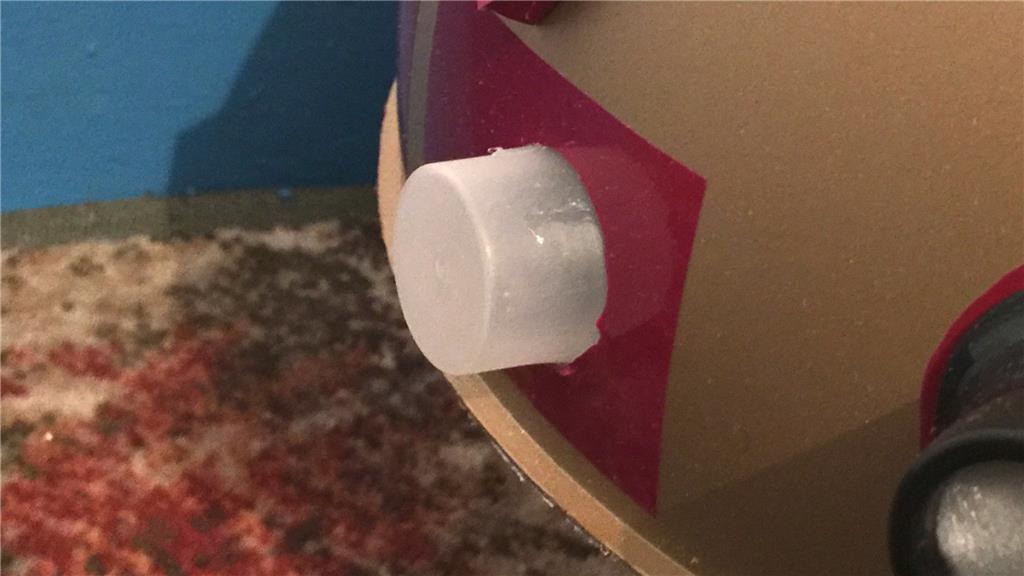
First off, I concentrated on the centre foot. I put the framework in for the foot to add weight and will act as supports for the foot side panels. I then added two stabilisers to the top of the foot to reduce side to side pivot play and keep the leg straight. Then I added the front and rear panels.
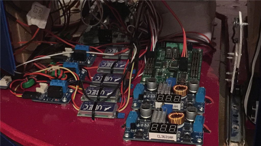
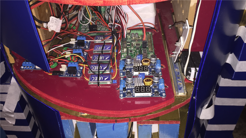
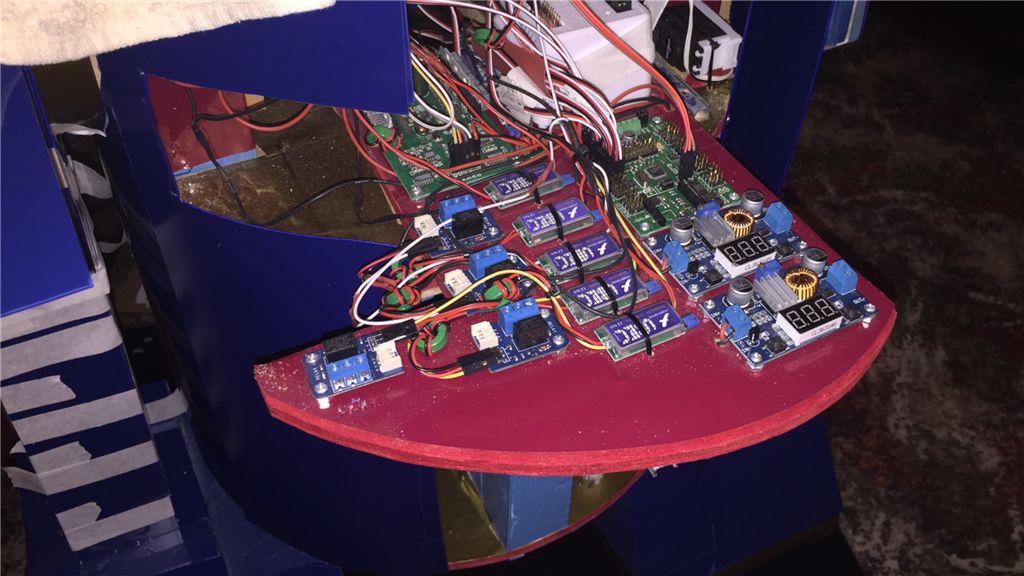
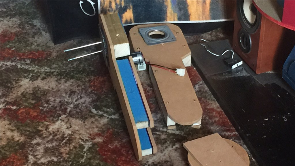
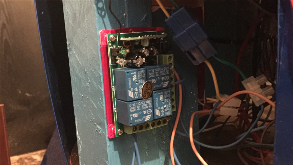
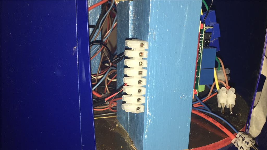
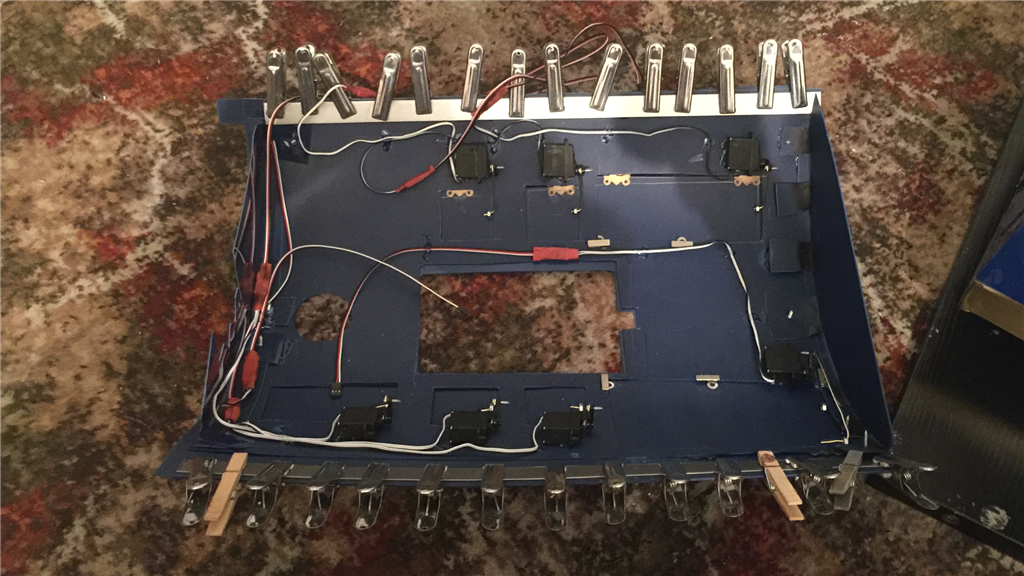
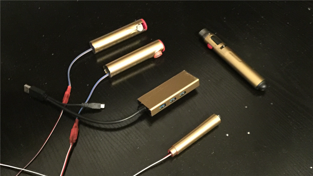
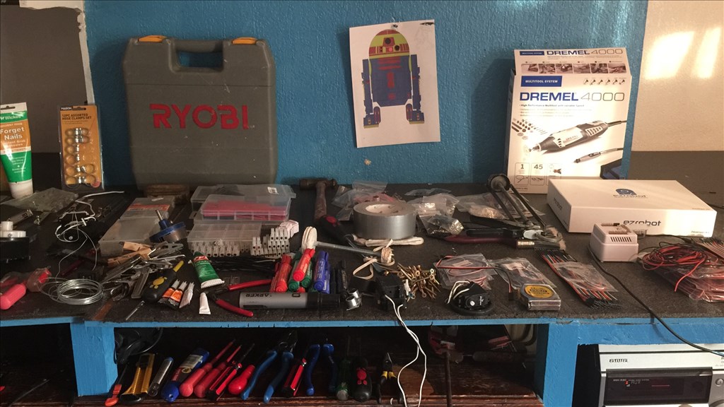
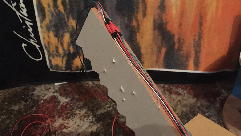
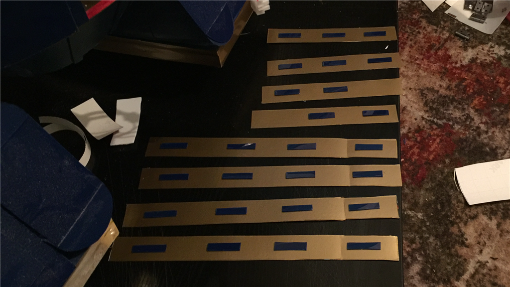
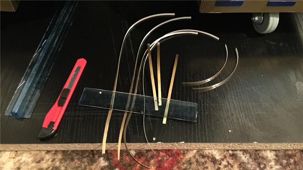
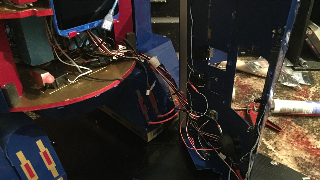
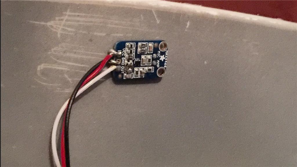
I've also started on the first part of the electronics. Actually, all I've actually done was to trace some wire which I will be using later.
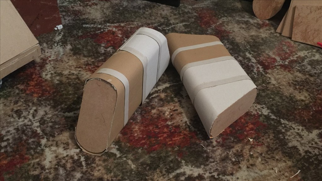
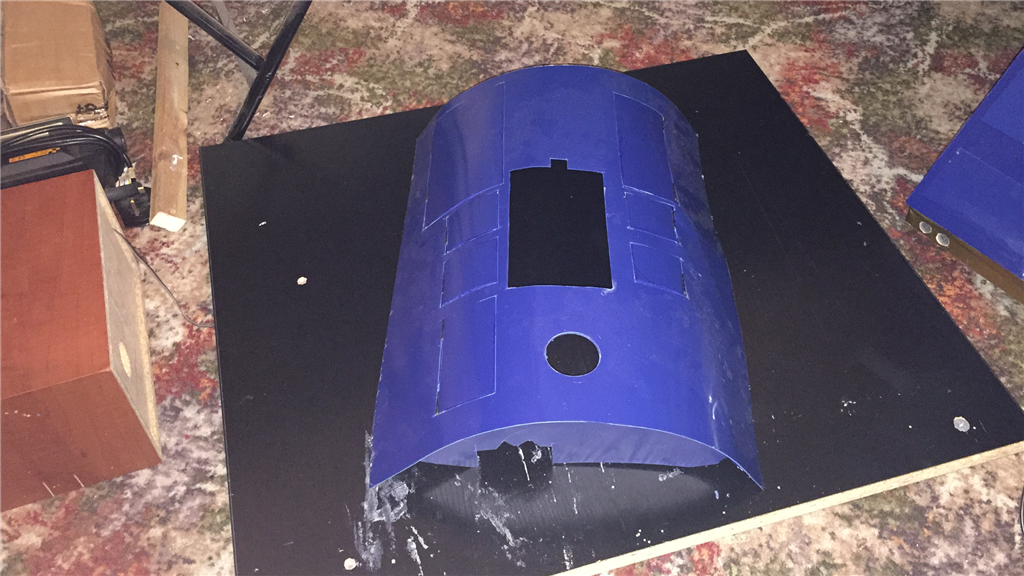
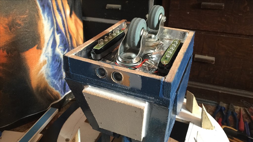
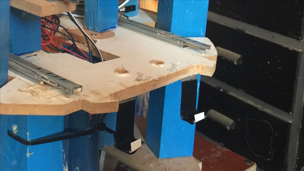
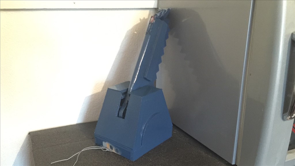
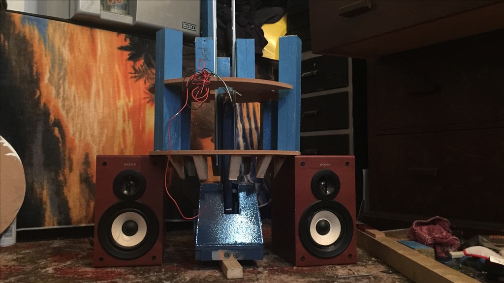
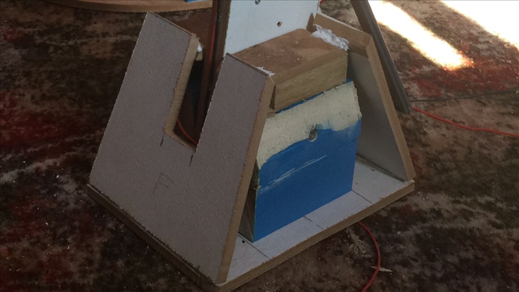
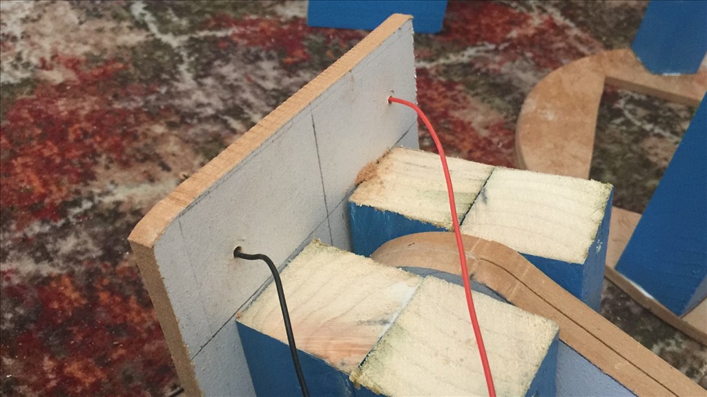
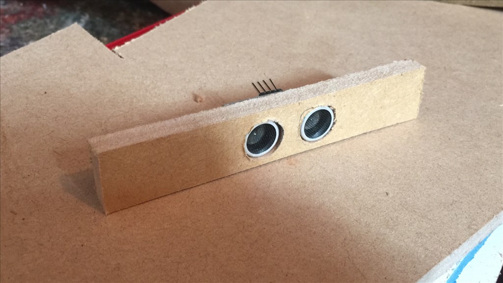
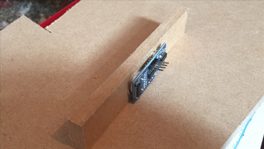
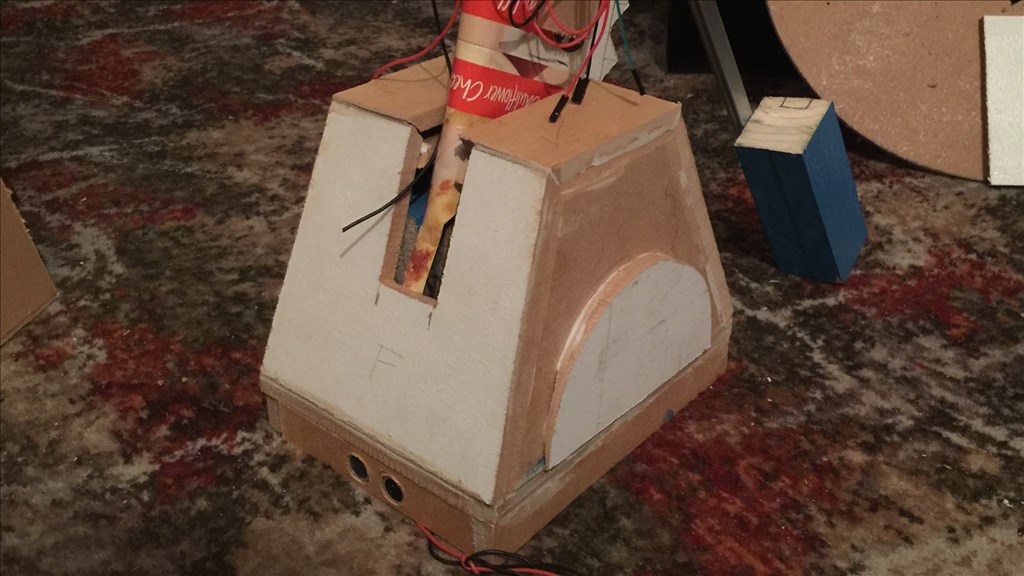
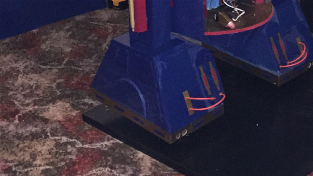
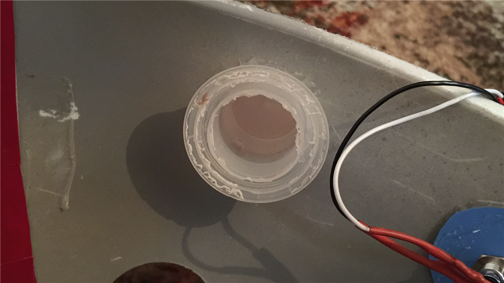
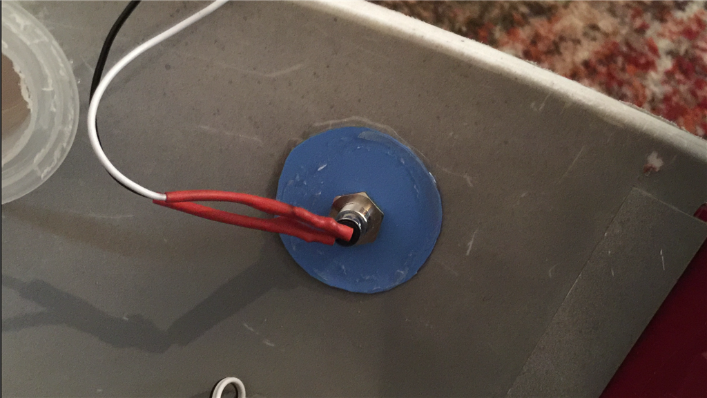
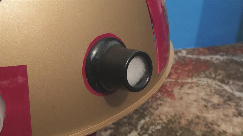
Carrying on with the electrical theme, I have now cut and attached the lower foot skirts, with the front skirt panel housing one of 6 ping sensors that will be installed in E4.
I added a few dabs of silicone and traced the wires to the front of the leg.
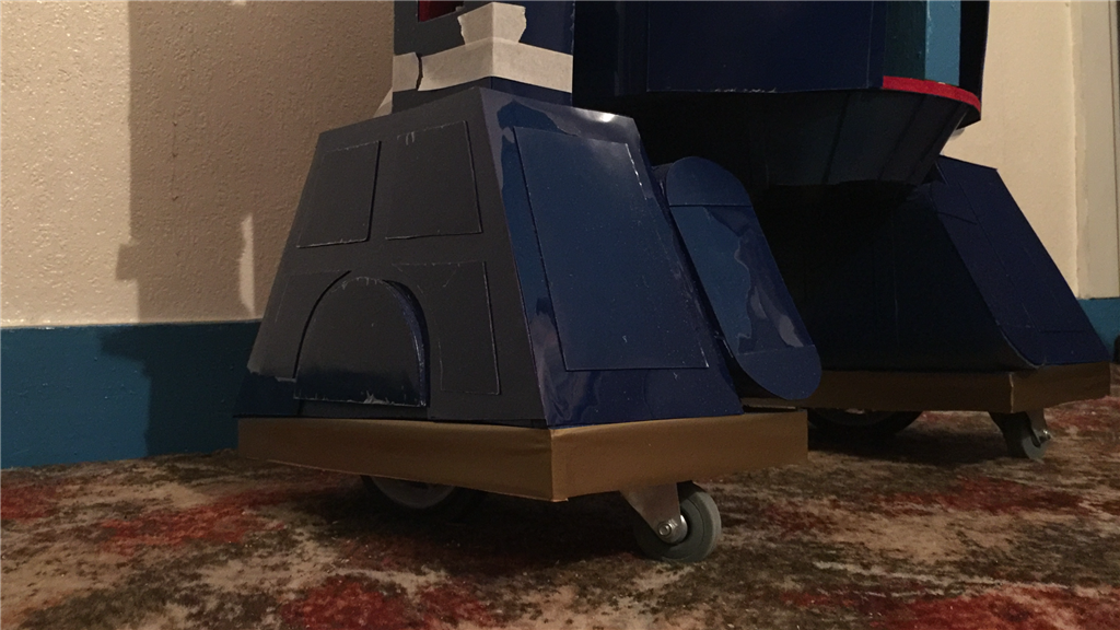
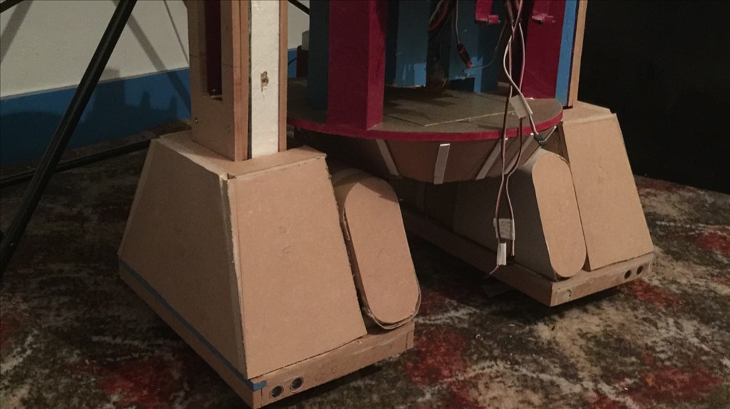
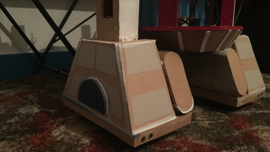
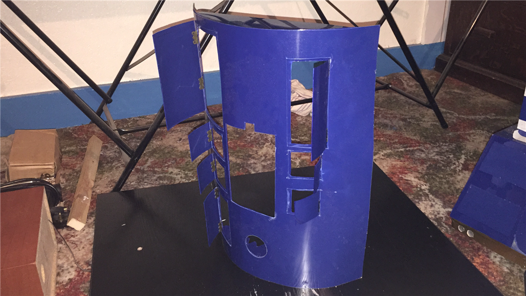
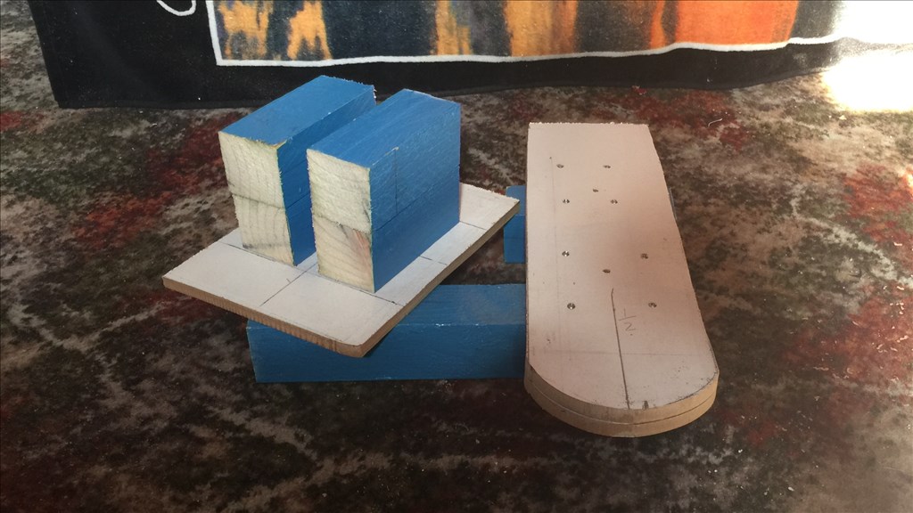
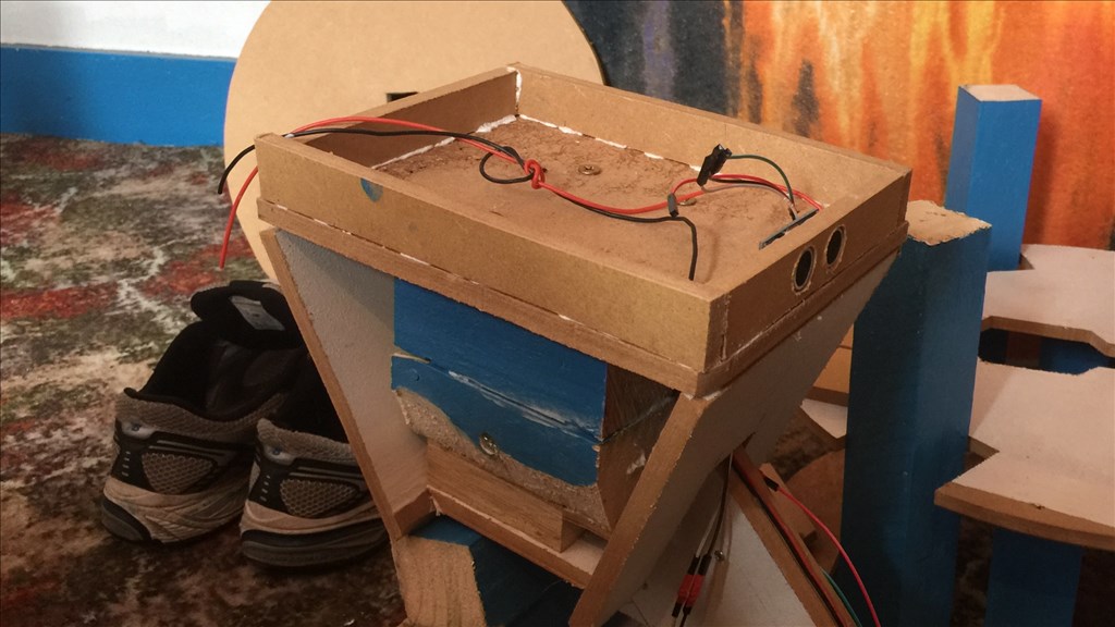
To finish off the main build of the front foot, I added the two top and side panels along with some detailing. The foot is now pretty much ready for paint and a few final details.
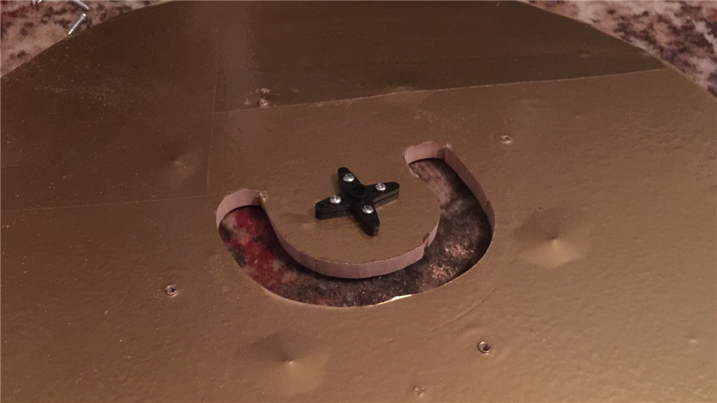
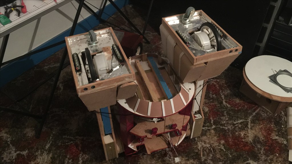
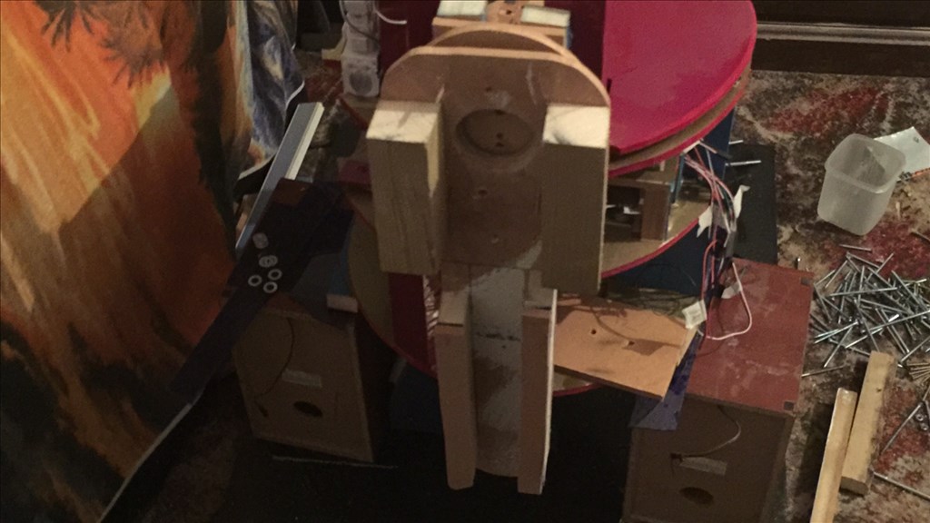
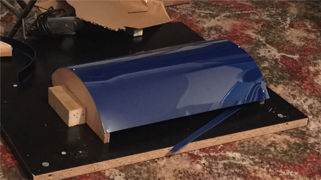
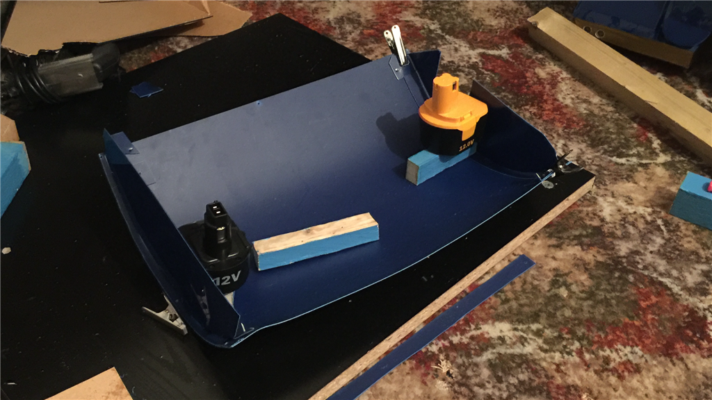
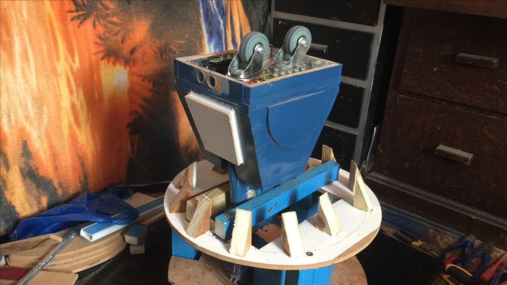
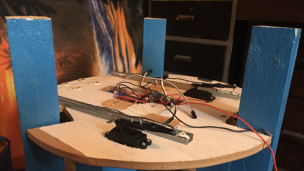
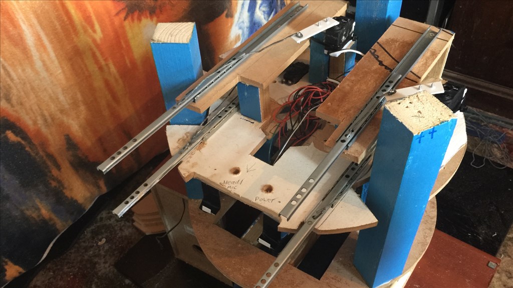
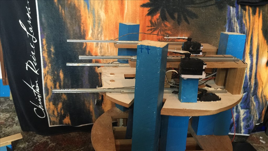
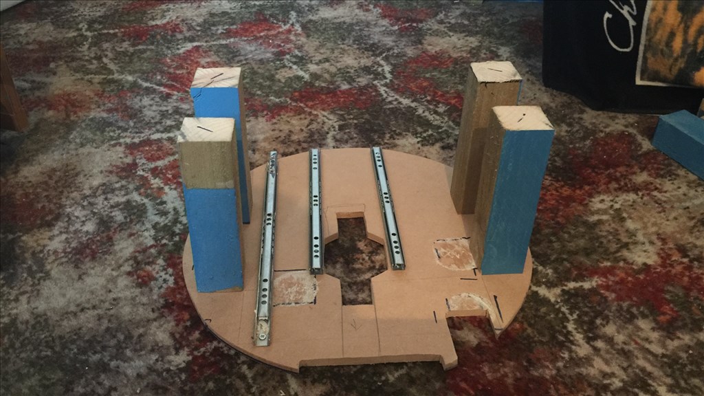
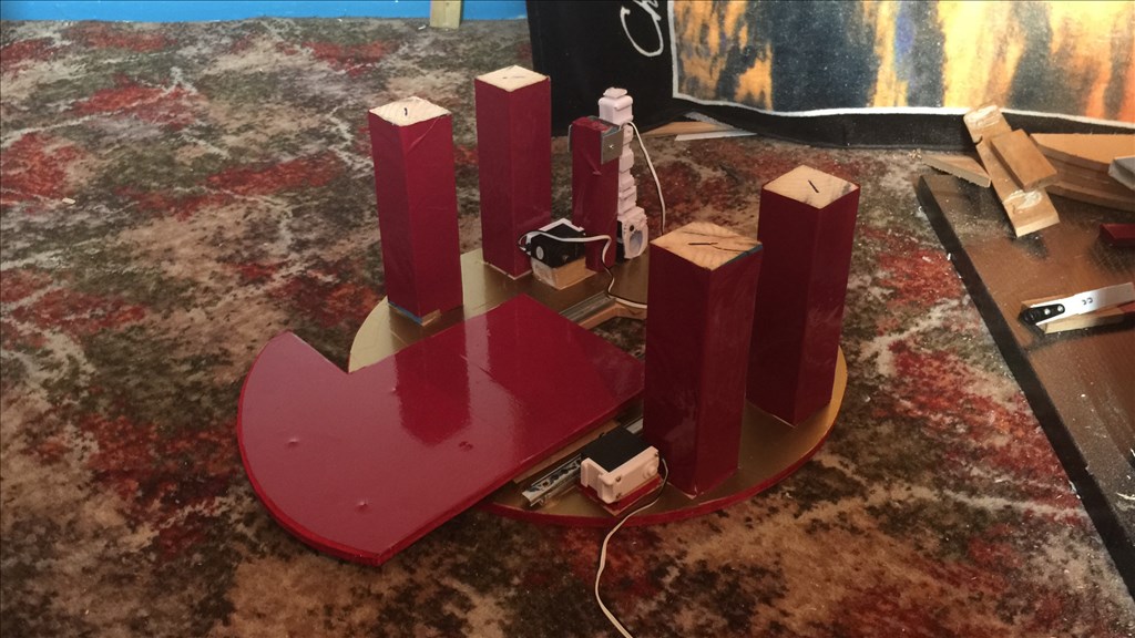
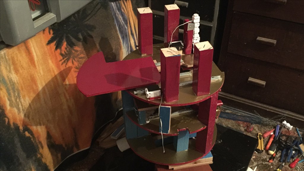
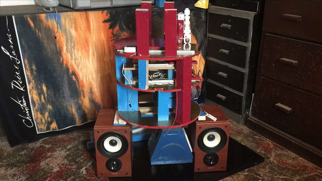
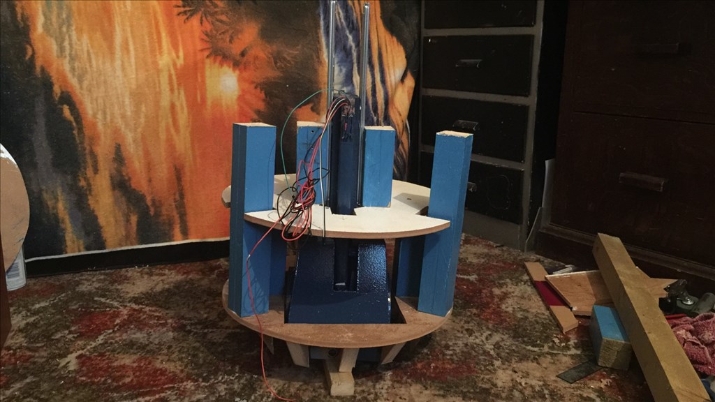
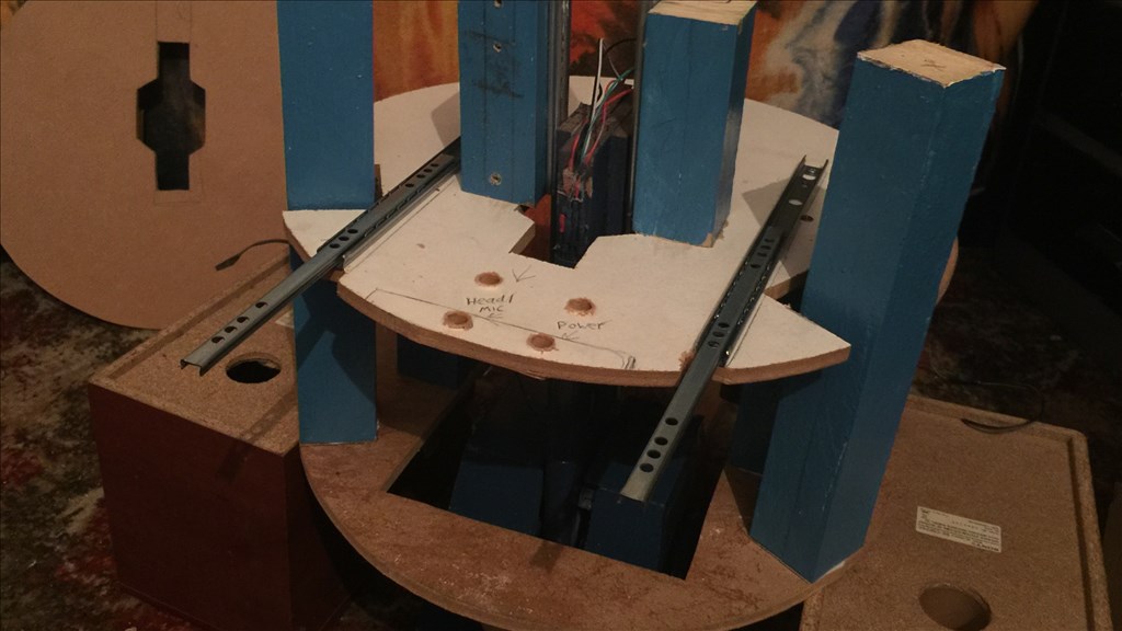
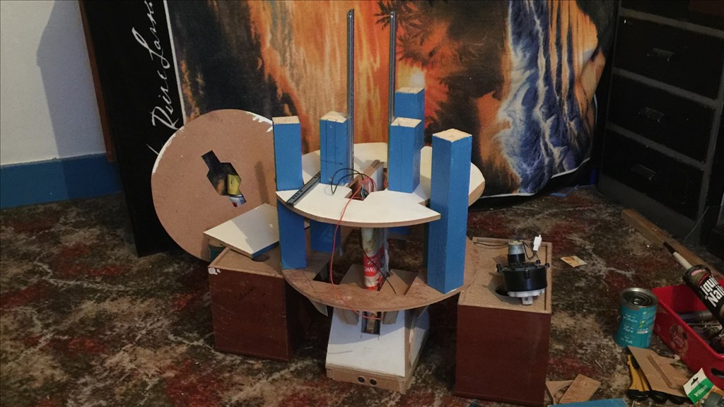
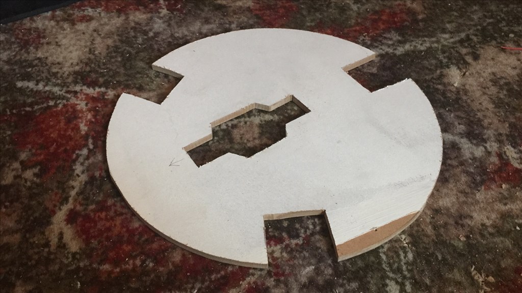
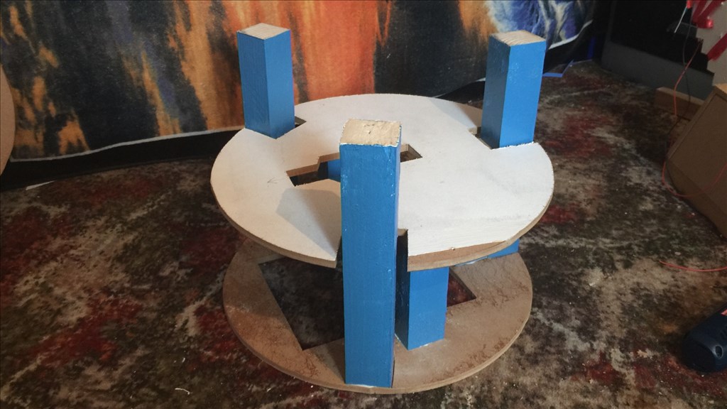
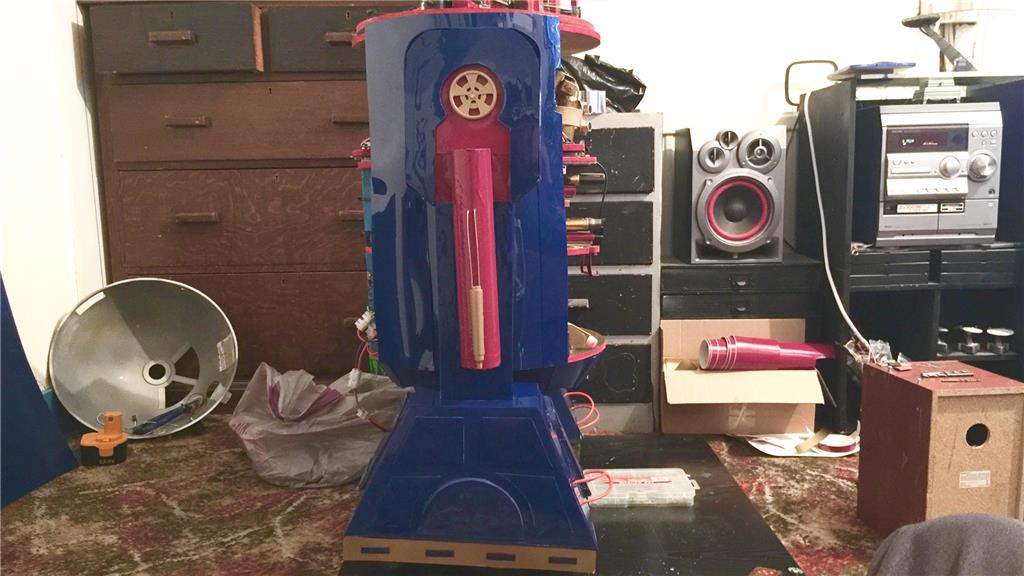
The next job was to cut an upper base panel and attach it to the body frame. This will support the foot mechanism.
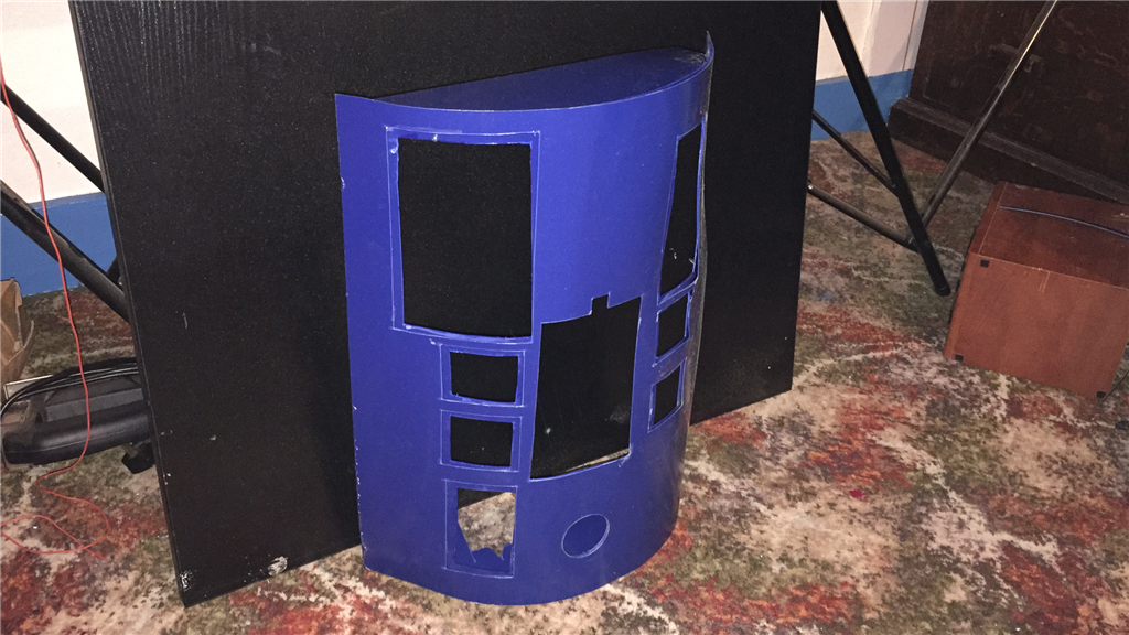
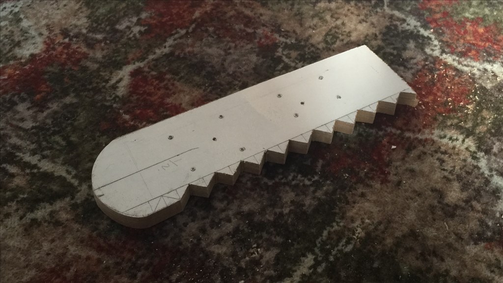
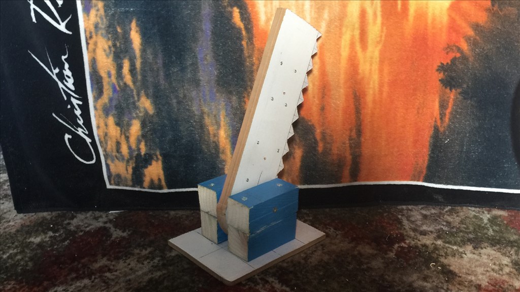
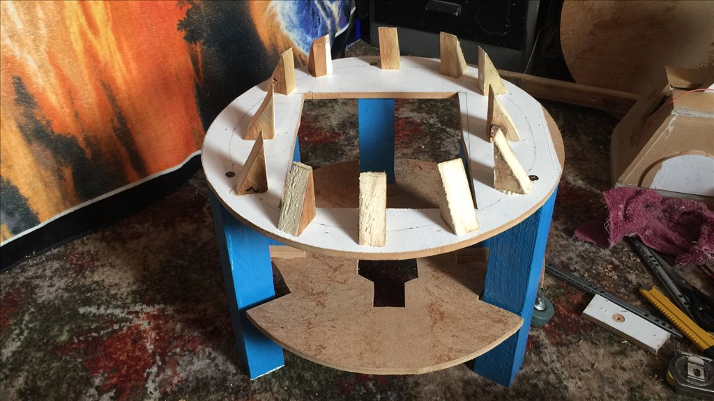
For the start of the body skirt, I cut out twelve 2" triangles to support the skirt skin which I will attach later.
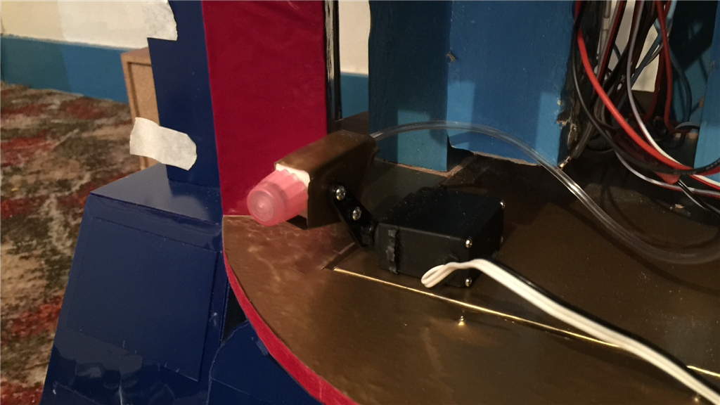
So that brings this update to a close. I've changed the idea of the "gear" system to raise and lower the centre foot, and instead decided to go for a pulley system with a servo interlock. This should be less strain on the motor, and I'm not 100% convinced that the gear assembly idea will work very well. Once the foot is painted, I will fix it to the body and look at fitting the motor when it arrives.
That's all for now.
loving your build and am following it avidly. I just have a thought on the ping in the foot, read somewhere that ping sensors don't like being too close to the floor because they can sometimes read the floor as an object. so give it a test to see if it's ok.
@bborastero.
Thanks for your comment. So far things seem to be going well and I'm enjoying this build so far and I'm glad you are enjoying the diary.
Also, thanks for the tip on the ping sensor. Bearing in mind that I'm sill yet to fit the caster wheel which will raise the ping up a bit from what's currently shown in the pictures, I will take your advise and test it to see if there are adverse effects. I can always relocate it higher up on the foot which will be an easy fix and will blend in with the final detailing.
What "scale" is this build, approximately?
@Zap.
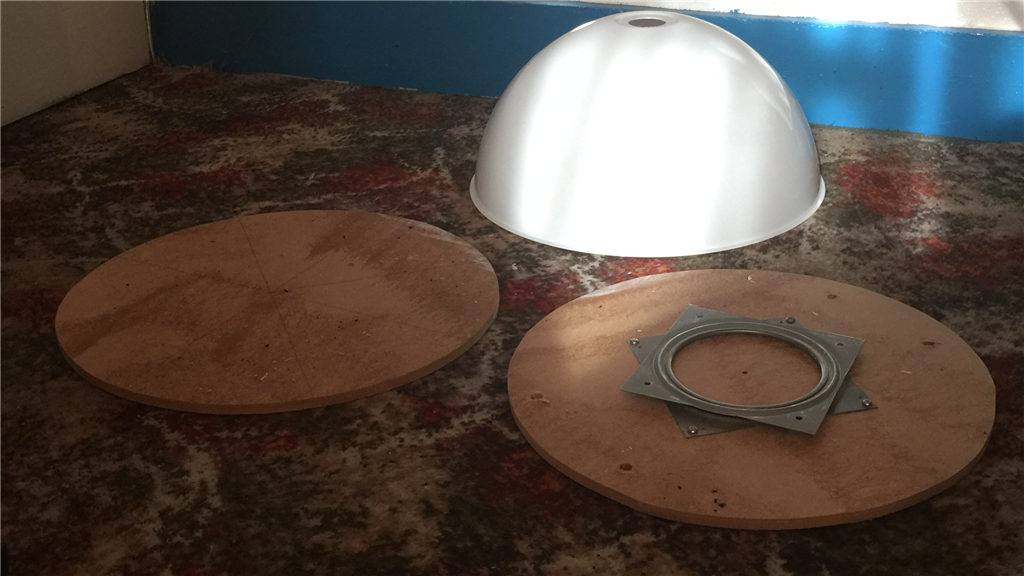
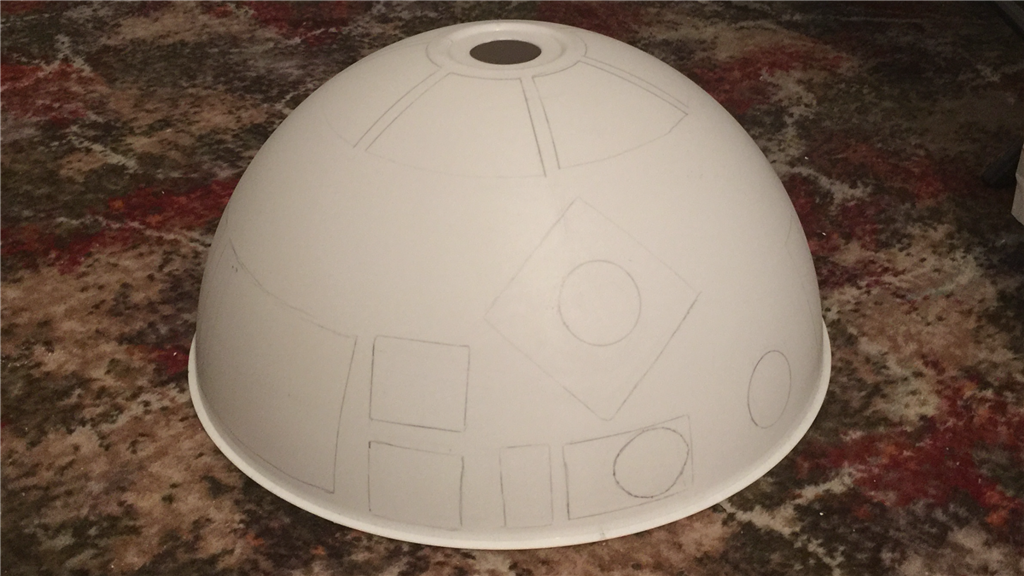
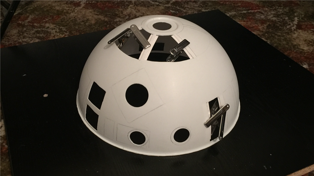
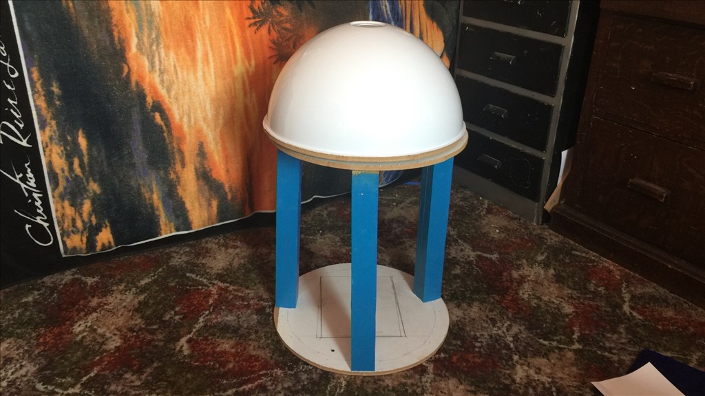
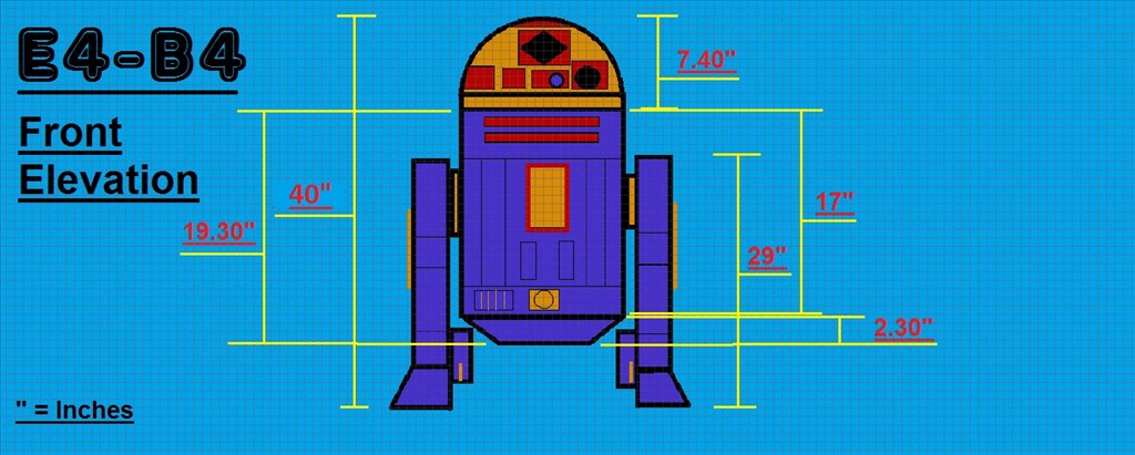
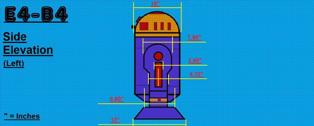
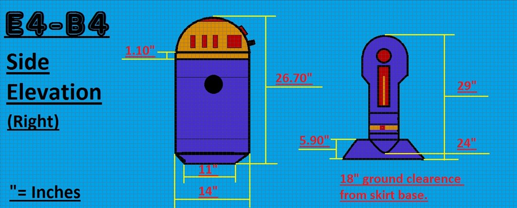
I'm going by some full size 1/1 prop build plans I found online a while ago, minus 2 inches here and there. The reason for the slight size change is the dome is normally referenced at about 18" diameter, and I have one at 16", so he won't be much smaller than a full size prob build.
Ok, that's cool. I was going to point you at some half scale 3D printed astromech detail parts but I think your build is too big for that.
@Zap.
Ahh, that would have been cool, but like you say, they would be a bit small. No worries though as its a custom build and not a replica to give him some individuality. Thanks anyway though. I appreciate the thought.