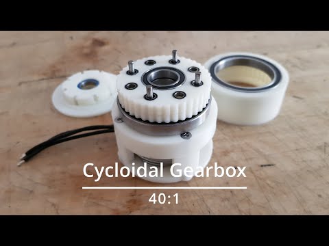

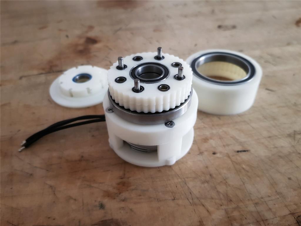
This is a WIP of a cycloidal gearbox with a reduction ratio of 40:1. It is driven by a Tarot 4108 brushless motor, in theory it should have almost zero backlash...
By Mickey666Maus
— Last update
Other robots from Synthiam community
Jdvann's My Dog
Dog (Droid On Guard): low-cost Dagu 4WD DIY robot to ward off boredom and help stave off Alzheimer's by keeping the mind...
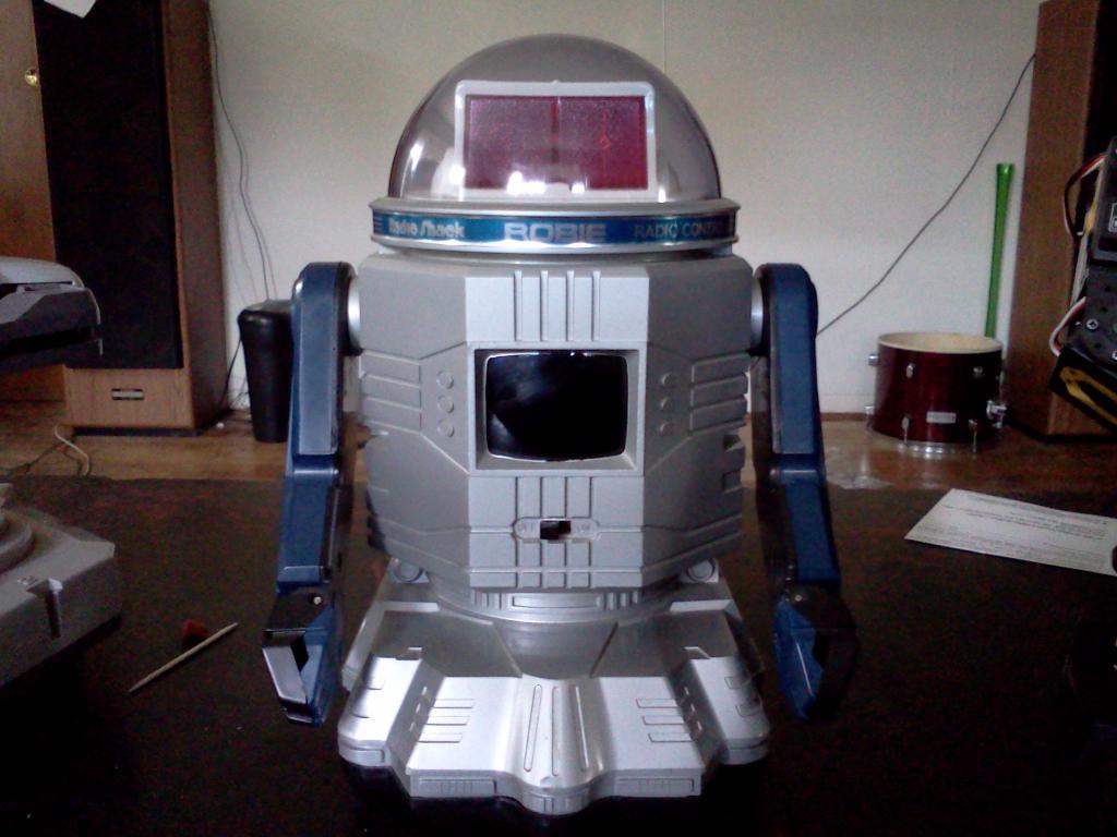
Kenny's Radio Shack Robie Meets Roomba
Convert a vintage 1984 Radio Shack Robie into a Roomba-mounted retro cleaning robot with ez-b, camera, and custom arms.

Robotdude's Lieutenant Commander Data
Data replica entertains ReStoring Data clients in Vancouver - head/arm SM-S8166M servos on EZB, face/motion tracking,...

Awsome. Looking forward to your progress on this. Do you know what your final torque will be when you on complete?
There is a lot of math behind it that I really do not understand. But I guess from kv value of your brushless motor, you can calculate the torque constant.
https://www.fxsolver.com/solve/
So the Tarot S 4108 should have a torque constant of 0.02512 Nm/A
Also you can calculate the revolutions per volt applied... The Tarot S 4108 has 380 rpm/volt or 39.79(rad/sec)/volt There is an online converter for this! https://lucidar.me/en/unit-converter/rad-per-second-to-revolution-per-minute/
So once the gearbox is working I will need to measure the amps the motor draws under load, but lets consider 2.5Amps... 0.029 * 2.5 = 0.0628Nm
By multiplying a gear ratio of 40, the ideal torque on the output is 0.0628*40 = 2.512Nm
But I really don't know much about all this...so please if anyone here knows better correct me before I blow up the next Power Supply!!
Interesting I tried the Chinese to english translator but it didn't work. WTF:p
Great job and that looks like mine. I have some bearings on order because I has to use ones that were 'closeish' on my first prototype. Interested to see how this goes. If you don't mind I will plop a few pics in this thread. Just an interesting side note here. I had a college prof ask me about how much torque a Newton meter is. I had no idea. He told me that a newton was equal to an apple. So imagine holding an apple on a 1 meter weightless stick. Remembered that all these years.
Have you guys ever seen this from James Bruton? I’ve seen real commercial products of elastic actuators recently and they’re really great.
Something like this can be 3d printed and use 2 springs. One on either side... I got it from this document: prismatic-sea-paine.pdf
@Perry_S yes please!!!
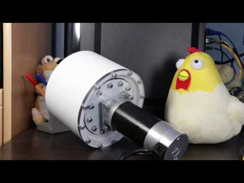
Actually I thought, I'll just throw my actuator in this thread to start the discussion!!
I got it working now, but the vibration is really heavy...lets see if I can reduce it some more!
What were your issues?
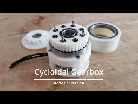
I will put together some links for Cycloidal Gearboxes that I used to build mine...
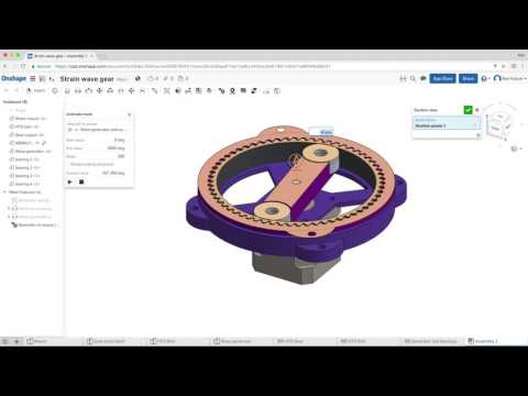
Which CAD software are you using?
I will upload all the .stl files once I got that gearbox ready!
@DJSures that looks great!! I am also following quiet a few quadrupets, James Bruton has two versions that he is currently working on...seems like elastic actuators are a big deal, when it comes to building a walking robot!! Super interesting!!!
Well - yes, walking robots can benefit from elastic actuators. However, I can see how they can be used for al joints and replace servo motors. I can envision a modular design that can replace a servo using an elastic actuator with a spring for the force measurement.