
jp15sil24
Wheel Slip Impact On Navigation
I am experimenting with navigation using my WheelBot and am considering modifying it into a telepresence robot. Currently, I'm utilizing a combination of the following ARC skills: Continuous servo Movement Panel, Better Navigator, Joystick, Camera Device, and RPLIDAR (Model C1). I've enabled the RPLIDAR skill parameters: use NMS and fake NMS pose hint event, and I'm using the pose hint source with Hector in the Better Navigator skill.
In one of my tests, the robot successfully navigated a 1.5-meter course and returned to its "home" position. However, during a second test, I noticed only half of the return path was visible. Normally, the entire return path should be displayed in green (refer to the LIDAR image below).
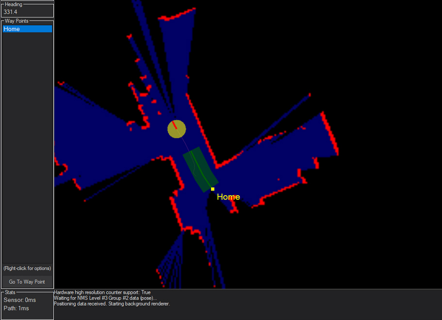
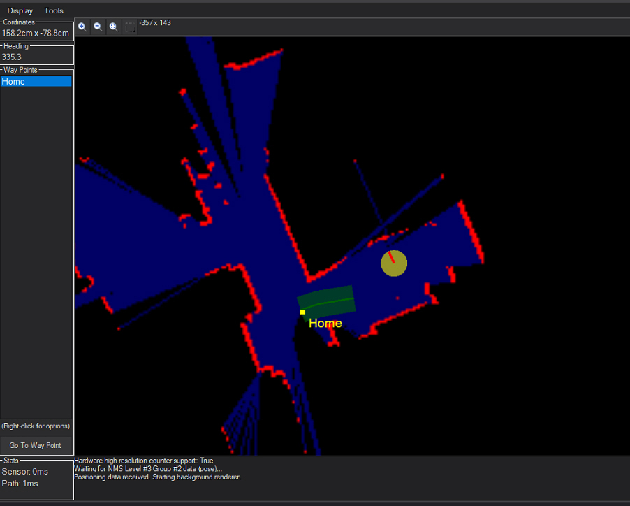
It appears that some information was lost during navigation. In another test, the yellow dot representing the robot was correctly positioned but then suddenly shifted to another location, as shown in the second LIDAR image.
The original position was similar to the photo above (LIDAR Image 1).
I'm not entirely sure if my observations are helpful in explaining this behavior, but I wanted to share them. My floor is tiled, and I've noticed the robot’s wheels sometimes slip, slightly spinning in place. I do not have encoders on the wheels. Could this affect navigation accuracy?
If wheel slippage is influencing navigation, could someone explain how wheels without encoders affect navigation?
If it's not related to the wheels, could you please provide some guidance on how to address this issue? I'm considering adding spikes to the wheels if this might help. Thank you!
Related Hardware (view all EZB hardware)
Related Robot Skills (view all robot skills)


ill make a try asap with your settings.
Oh the robot has no rear view. A little less than 50% of the scan is missing. The trouble with how slam works is gonna be a problem. Slam tries to determine where the robot is on the map by looking for distance measurements that position it within the previous map.
when a huge part of the data is missing, there’s no easy way to identify the location. Specifically because there isn’t enough stored map data to compare against.
use a Dremmel and cut a hole in your holder behind the lidar.
when I get home I’ll take pics of my setup on one of my robots that has a camera and sensors above the lidar. That will give you ideas.
ok. I will see your design and modify mine.
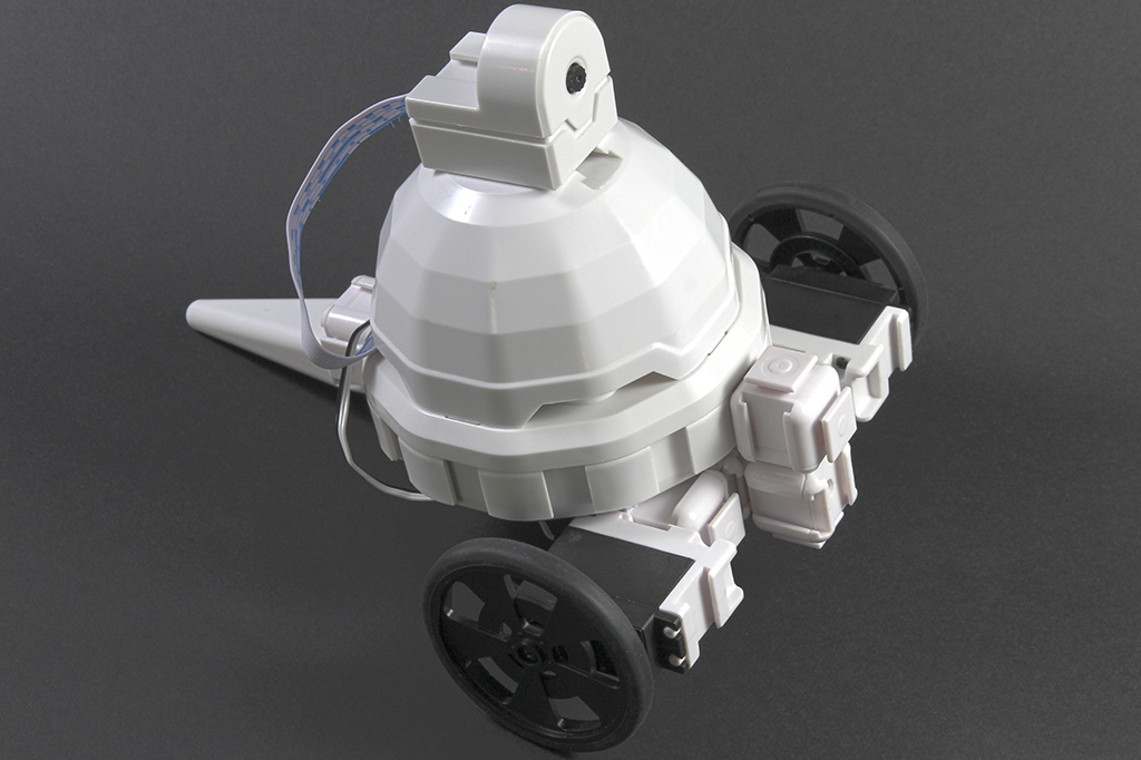
I’ve modified my robot’s design based on the example shown in the video "Add LIDAR Navigation to a Robot." I’ve attached some photos for your reference.
At the moment, I’m unable to test the navigation because of a power issue-my battery shut off unexpectedly, and now Windows won’t boot. I’ll need to resolve this problem first before I can begin testing the navigation features.
I really hope the new design is correct, but please feel free to point out anything
That does look closer to what DJ might have been referring to. It is a holiday weekend, so no one is really around.
I do have two concerns about your change.
many thanks for your help . I will modify according to your recommendations. I always thought the position of the t265 is not that critical, just facing the front.
Oh yeah that’s good suggestion from support. It’s crazy how important the measurements are - until you realize that a small error in the math continues and grows over time.
The t265 is okay but I don’t use it often. I find it really starts to drift. Sometimes I’ve seen a drift of 20-30 cm over a short period of time. The problem with the drift can usually be resolved if using the last option (I think) in the pose hint type in the better navigate. I think it’s the last, I can’t recall top of my head.
but the last option uses the difference between the slam and the external (t265) and keeps the difference for the next time.
Yeah - Dynamic is what it's called. This is from the Better Navigator robot skill manual page.
However, I'd first ensure the lidar works correctly by using "Hector" as the pose hint type because that will depend entirely on the lidar's positioning and scanning. The lidar's map will be the best option for determining where the robot is on the map, without using external sensor data. Once you get that dialed in correctly, you can add additional sensors. For example, only add one sensor at a time to ensure they complement each other.
If you do use Hector as the pose hint type, don't have any other odometer pose data being sent into the NMS, or it will confuse it.