Asked — Edited
Resolved Resolved by Herr Ball!

Can The Iotiny Be Made Into An Openai Chatbot Connected To ARC?

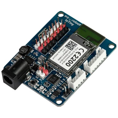
Can the IoTiny be made into an OpenAI Chatbot connected to ARC? My thought is yes based on everything I have seen on this site so far but I still have a few questions I hope can be answered.

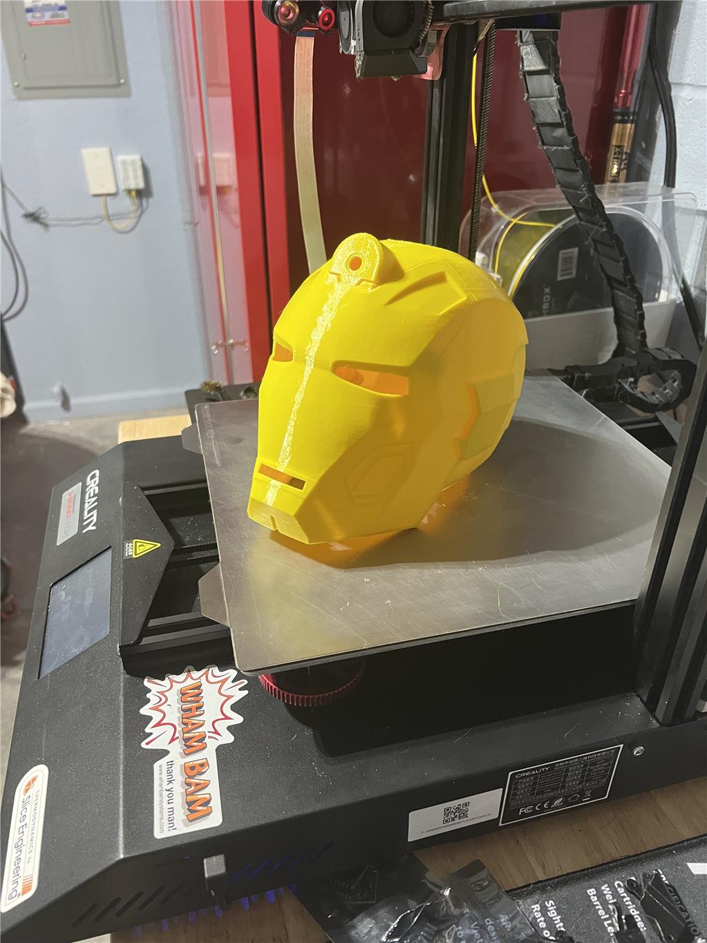
Goal is the following: Make a Robot head using the IoTiny connected to ARC over wifi with a EZ Robot camera attached to it and a speaker for audio out. Two 3V LED’s connected to the ADC ports to make the eyes light up and some type of LED/RGB setup for the mouth to to come on this. User-inserted image

I want to use the following skills

  1. Openai Chatbot robot skill with audio out going to the speaker on the IoTiny.
  2. Bing Speech recognition robot skills taking audio commands from a headset to the ARC PC.
  3. Camera Cognitive skills

Here are a few of the questions I have

  1. Does the IoTiny speaker out need to have and audio Amp added to it like stated by Jeremie "There is no DAC breakout on the IoTiny but you can solder to the left side of C11 if you'd like to run the audio to your own amplified circuit. Or can your just add a TDA2030A Audio Amplifier Module to the existing speaker pins?

  2. For the mouth I want to be able to do something like the following on the IoTiny also.

Check out the following video: https://www.youtube.com/shorts/M9N4cfYbx5A

This is a project Derek Levesque and what he used was MAX7219 Dot Matrix Module 32x8 4 in 1 LED Display Modules for Arduino Raspberry Pi Microcontroller with 5Pin Wires and then created some nodejs/raspberry pi (ubuntu) code like the following. It looks like I would need to EZ-Robot I2c 8x8 RGB module the question I have is there a way of programming it to do the same type of thing based on the OpenAI’s Response?

So DJ/Jeremie or anyone else, I would love to hear your comments.


Related Hardware EZ-B IoTiny

ARC Pro

Upgrade to ARC Pro

Unlock the true power of automation and robotics by becoming a proud subscriber of Synthiam ARC Pro.

#1  

Yo! When I go to the above link Question 2. It states the video inst available anymore.  Would like to see what you wanted to do? I did have a LED array setup, that was years ago though?

PRO
Synthiam
#2  
  1. load arc

  2. connect to iotiny

  3. add open ai chat robot skill (configure it as per instructions with an open ai account) (https://synthiam.com/Support/Skills/Artificial-Intelligence/OpenAI-Chatbot?id=20207)

  4. add bing speech recognition robot skill (https://synthiam.com/Support/Skills/Audio/Bing-Speech-Recognition?id=16209) - edit the robot skill and use the ControlCommand() to send the $BingSpeechResponse variable to the AI Chat Bot robot skill

  5. If you want a mouth to move, then add the Talk servo robot skill (https://synthiam.com/Support/Skills/Audio/Talk-Servo-v2?id=19940)

Done. It should be about 14-16 clicks of the mouse

#3   — Edited

I have updated the video showing how I want the mouth to work.  So DJ no extra amp is needed for the IoTiny with a larger 2" speaker on it?  Also DJ the mouth does not move I want it to work like the video I attached.  Can you provide more input on doing that type of thing in ARC?

PRO
Synthiam
#4   — Edited

Probably use adc on an arduino from a servo port run by talk servo to turn on and off leds by the value

I don’t know if you need an amp. You’d have to check and see.

#5   — Edited

Quote:

So DJ no extra amp is needed for the IoTiny with a larger 2" speaker on it
If you are looking for a good full sound you will not like the quality of the sound coming out of the Iotiny (or and EZB for that matter) with any kind of speaker attached to the speaker output pins. Just my opinion if you're looking for a nice robot voice.

I'm not a speaker guy and have not tried to attach any larger speakers to the Iotiny other then the very small one that it comes with it. I do know you need to match your impedance between the speakers and amp or you could have problems. I have read that you can have problems even if your impedance is matched with the wrong speaker. You can burn out the speaker coil and the output. Here are some things I found:

Quote:

But let us assume you already have a sound system with speakers with the correct impedance. There is another way speakers can damage the amplifier. And it usually starts between the listener's chair and the amplifier. It works like this: The listener pumps up the volume way up. The amplifier does not like it. It starts to peak and distort (clipping). While this is happening, the listener is just enjoying the loud noise coming out of the speakers. The loudspeaker drivers coils start to heat up. They heat up to the point they start to melt. This brings their impedance down to dangerous levels until it shorts the output of the amp. When this happens, suddenly there is pandemonium on the output stage of the amp. The components do not like it very much and become uncooperative. They decide to heat up and crack. And there you are. You have some blown speakers and by osmosis a blown output stage.
More specific to your question, having an underpowered amp connect to a big speaker:

Quote:

Interestingly, it's more common for speakers to be damaged when they are used with an amplifier that is underpowered, rather than being overly powerful. The reason for this is quite simple. If an amplifier is underpowered, you're more likely to crank up the volume to high levels to increase the loudness.
Here's a good easy read article for you to help make your decision: Can Speakers Damage an Amplifier? Here are the Facts! Here is the big take away for me in the above article: 

Quote:

For speakers to damage an amplifier, the speaker’s impedance must be lower than the amplifier’s impedance. Most power amplifiers are designed to drive speakers with an impedance between 4 to 16 ohms. However, several factors can cause a speaker or a set of speakers’ impedance to fall below the amp’s acceptable impedance range.
I don't know the specs of the Iotiny onboard amp and how high you would have to raise the volume of the speaker to get a good sound but once you match the impedance I think it would be safe to experiment.

If you just want to keep it clean and fast and take all guessing out of this, solder a breakout circuit for a stand alone amp to C11 and a ground like Jeremie mentions. If you connect an amp to the output pins you will be connecting to the sound output "after" the onboard amp. Connecting to C11 should connect before the onboard amp. At least that's the way it is on the full sized EZB v4.

#6  

@Dave, thank you for your post I kind of think I am going to need do the solder connection to get the quality and volume needed.

@DJ,  The other issue I have is I need a way to connect the Mega to ARC using Wifi which was another question I posted here.  What I was trying to do is provide everything with the IoTiny.  If I connect and LED to the talk servo port would it flash/flicker based on what is being said?  What I am looking for is also kind of like how the B9 chest light flashes when it speaks.

#7  

Hey smiller29

You mentioned above about a LED and Talk Servo. Just wanted to show you something that might interest you?

Link: I made this years ago and it turned out good. By that I mean it worked good. There is a video at the bottom of the page. That will show you if it would work for your needs. I ran it off a Arduino Pro. The problem is I don't know if it ran off a mic next to my speaker like in this article or if it was connected to my EZB? It seems like it should not be that hard to connect to the EZB. Having a Brain Fart here ... lol. I will dig back into the past on my PC (lol) and look for the circuit. Go down the page to the mouth assembly. Just throwing it out there. Good Luck!

#9  

Herr Ball,  that looks like it could work thanks for posting it!

#10   — Edited

If you can't use a wifi shield on your mega perhaps you could get a Arduino Mega 2560 REV3. It has built in wifi.

Arduino Mega 2560 REV3

I just don't know if Synthiam's flash firmware will work on this new MEGA and take advantage of the wifi. I've never flashed anything and turned it into an EAB.

#11  

@Dave,  The firmware for Mega to ARC/EZB support is not updated I have another question posted on the site asking if that could be updated but have not seen any feedback on it yet.

On another note Dave how did you make the B9 chest light flash when it speaks.?

PRO
Synthiam
#12  

What do you mean the firmware for the mega ezb/arc isn’t updated? It’s a reliable and great working firmware that doesn’t need an update. What update to the mega are you expecting?

#13  

DJ,  What I meant was the Mega firmware was not updated to support Wi-Fi connection to ARC at this point to Dave’s post.  My other Question I posted in another thread is asking if anyone has made a firmware update that can allow the Mega attach to ARC over WI-FI like you did with the ESP32 firmware.

PRO
Synthiam
#14   — Edited

You can always try that with esp32. Just use the esp32 as a uart relay and connect it to the mega rx0 and tx0 pins

or you can modify the mega firmware to work with the mega wifi variant. It’s a pretty rare unit but the documentation for their wifi api should be easy enough. Look at the esp32 firmware to see how it’s done. It might be close

#15  

@DJ,  I am going to try to update the firmware myself using the DFRobot Gravity I/O Expansion Shield for Arduino v7 and the DFRobot ESP8266 Wifi Bee module.  I really want to be able to use the mega connected to ARC over Wifi.  Can you confirm if I can still use the serial ports on the Mega with the current firmware?  I want to be able to connect other Arduino's to them.

#16   — Edited

@smiller29,

Quote:

On another note Dave how did you make the B9 chest light flash when it speaks?
The B9 Robot Builders Club has a member/vendor over in Australia, Steve Neal, that makes a small board that interfaces with an amp that will trigger the flash. Don't let the fact that he's over in Australia put you off. I've ordered several of his boards and they arrive in a week or so. Our builder members have started using his little board because they not only work great, are easy to adjust but work better then what has been commercially available in a long time.

Now, here's the thing. This board has a 12volt input for power and a 12 volt output along with a trigger wire to send a signal for the flash. I've not used this board for any other purpose other then to get a neon to flash. A neon setup requires a special transformer installed after the board that will accept the 12 volt from the board to transform it into a high voltage pulses when the trigger wire sends a signal. The transformer will then deliver a pulse to the neon to get the flash.

Cost plus postage: Fully Assembled: $35 Assemble Your Self Kit: $21

I've talked to Steve many times and he has stated that this board can be used for other types of lights to get a synced flash from an audio source. You eliminate the neon transformer and change the output wiring. However again, I've never done this and don't know the proper connections. If you are driving LEDs I would imagine the proper sized resistor would have to be used to knock down the 12v to a useable voltage for the LEDs.

If you are interested I can reach out to my friend Steve and get the proper instructions on how to use this board in your application. He is very quick to respond and get the order posted. He offers these boards already assembled (takes longer to get shipped because he has to solder it al together) of as a kit that you can assemble. I'd need to know what light source you are using and what device (if any) you have it hooked to. Feel free to contact me through email but posting here would probably benefit other builders.

So, here is a link to his vendor page in our B9 Robot Builder's vendor area. You will find a lot of info about this board and how it's used in the B9 Robot build. Again, remember Steve says it can be used in other applications. You'll also find wiring drawings that show how to wire it up to an audio source and the B9 chest neon. There are also a couple videos on that page showing how it works and how to install it. The install video on that page was made by me.;)  :

For some reason when use Chrome and click on an embed a link I place in this post it takes me to a page that says "Page Not Found". So copy and paste this address in your browser. Hopefully that will take you there.  http://www.b9robotbuildersclub.com/pub/parts/B90658/index.html

Here is the embedded link to the above address that does not work (for me) for some reason: http://www.b9robotbuildersclub.com/pub/parts/B90658/index.html

I'll go ahead and reach out to Steve and check a few thing out for you on this. I've been wanting to catchup with him anyway.

#17  

Dave thanks for the information I will take a look.

#18  

Hi Steve, For my inmoov I used a tiny with a 2" 2-ohm speaker. I was amazed at the volume and quality. I printed a small enclosure for it that fit into my inmoov head. If I can ask, why do you want to use a Mega? Do you have plans to expand. Everything you are looking for can be accomplished with just the Tiny plus it has wi-fi access already built in. For lighting I like the neopixel rings, There is a control here for them.

#19  

Hey Dave, I wouldn't mind looking into getting one of those boards too, sounds very interesting. I tried the links above but all I get is "unsecure web site".

#20  

@Dave I also am having the same issue with the website.

@Perry_S. In this project I have 40+ servos to manage and currently one Seeed Studio XIAO&6050MPU I need to connect to a serial port on the Mega to send XYZ data.  The original plan was not to use ARC at all and just code everything and build a Bluetooth controller to operate the robot.

The real goal of this project is to get the robot walking and stable.  But looking forward If that can be done then I would also like it to do more and ARC would make that easier in the long run.  So currently the plan is to put the IoTiny in the head, with camera, a speaker and Seeed Studio XIAO & Mic to make the mouth work.  This will all be connected to ARC to support the OpenAI, Speech, and Camera skills.

The Mega  is going to be the main logic for movement control.  The plan is to use inverse kinematics formulas to develop the walking gait need. All of the other servos will be connect to a 32 port RTRobot board and the Mega will send the commands to it also by Serial port.  So I need the three serial ports on the Mega.  Because this guy is only like 4ft tall he does not have a lot of room for electronics and batteries.   We designing an added backpack to try and put stuff in there.  Anyway I hope that helps to give you more of an idea.

Note I always love to here other ways of doing stuff because this is still very new to me only being a year into this hobby.

PRO
Synthiam
#21  

I think the mega is suitable but I’d probably consider only one wifi point and a wired network across all other arduinos. Implemented like the stepper motor robot skill.

You don’t need them all to be Megas. Just connected together with one long serial network.

as for the mega controlling the legs, write a bit of code that uses an imu to maintain an inverted pendulum (there’s example code in the balance robot on here). Once you do that, create a few functions in the mega that have to robot walk. Finally, have those functions triggered by arc

you don’t want to offload the balancing act to ARC or any external processing (like a computer). You need the balancing to be a tight loop on the microcontroller - without exception. The time between measuring the sensor and adjusting the servos needs to be as low as possible. And I mean low. Like a millisecond or 2 -  not over wifi or serial. It needs to be on the microcontroller.

#22   — Edited

Quote:

"unsecure web site". @Dave I also am having the same issue with the website.
Ugh, we sometimes have this happen with people trying to access the clubs website. I don't know why and I guess I need to look deeper into it. However, I assure you that it is safe to proceed. I've maintain this site for many years and know it to be safe and secure. So if you still want to view the site then you'd have to look at the bottom of that waning screen, click on the "proceed anyway" link (or something like that) and then OK the trip on the next screen. Sorry.

I really think this voice interface board is a wonderful tool to use when you want to sync a flash from any kind of light source to an audio source. It's inexpensive, small, reliable, easy to use and well made.

Here's the response I got from Steve last night when I asked him about using this board with LED's and not being triggered by a transformer linked to a neon:

Quote:

Yes my board is simply like a switch that is triggered by an audio input and will happily run LEDs. All it really does is simply supply what ever voltage you put into it at the output terminals in sync with the audio. You can defiantly run the LEDs with 12 volts with the appropriately sized resistors, actually the board only supplies to the load whatever voltage you put into it. I think it can work as low as 9 volts but I've never tested that. I have attached the power connection diagram and if you look at figure 2 it shows how to connect an LED strip to the board. This is actually the method I use to test the boards when I make them. I hope this answers you question, please let me know if I can help further.
So, if you are still having trouble getting into his vendor page on the B9 Robot Builders website I'll post the most pertinent info and links below:

Contact:  Steve Neal Email for questions or to order: Steve.B9@bigpond.com

Ordering: The Neon-Voice Interface Board V1 can be ordered as a fully assembled completed board ready to plug in and enjoy. It comes with detailed easy to follow instructions complete with clear diagrams to make connecting to your robot a breeze. For the more adventitious, the board can be supplied as a kit you build yourself. It comes complete with the Neon Voice Interface V1 blank board, all the components required, easy to follow assembly and connection instructions and of course, diagrams. Each component will be labeled with a designator number that corresponds to the footprint labels on the board.

Price: Fully Assembled: $35 Assemble Your Self Kit: $21

Here is the power circuit. Remember to adjust the output voltage with the proper value resistor if your light source is rated for less then the input voltage:

User-inserted image There are many ways to connect a sound system. Steve supplies many diagrams to assist. Here is one that may make the most sense for robots using one sound source: User-inserted image

#23  

DJ,  I was going to try to connect the Mega to the Iotiny's Wifi AP as a client if I can and have the Seeed's hardwired to the Mega.  I was wanting to build out the EZB mega firmware to basically do what you are talking about.  But first I need to get the Wifi stuff worked out in the firmware.  I have to tell you this Xbee ESP8266 and Mega setup has been a challenge understanding where and how to program it it looks like some code needs to go in the xbee and some in the mega but I can't seen to figure it out yet but I will get there I hope.  LOL

#24  

@Dave,  that is cool but I need to be at less voltage the method Herr Ball provided basically does the same thing so I am going to go down that path because it looks kind of straight forward.   I ordered the supplies to give it a try anyway...  Time will tell if it works as planned.

#25  

That's cool.;) . There has been other people asking about this too so maybe this info will help someone. I have no skin in this game with this sound interface. Just want to help.

What voltage will you be running at?

#26  

@Dave for that part of things 5-7.4v is the plan but like everything else that could change. xD

PRO
Synthiam
#27  

I really dislike xbee. I avoid it at all costs so can’t help you much there.

#28  

DJ. Are you saying it would be better to just order a mega with the Wi-Fi on board?

PRO
Synthiam
#29  

It would probably be easier to have onboard wifi. And less hardware required

#30  

I just want to thank everyone for their input it has been a big help once together I will post a video.

PRO
Canada
#31   — Edited

I wish I had been on here earlier! I took a bit of a longer break this holiday season to look after my kids and nephew who had an extra week of vacation.

I wanted to mention that I've had great results with porting the IoT speaker to make it louder. I did a bunch of experimenting and found a decent method of 3D printing a small chamber that increases the sound from the speaker by at least 1.5 times. It also deepens the sound, bringing out more of the lower-frequency bass tones. I was pumped by how full the music sounded with porting. I will officially measure it when my decibel meter arrives next week to see how much lower it goes.

The TS4902 amplifier chip on the IoTiny/EZ-Bv4 will put out 0.3W so that's your maximum power output but if you increase the speaker size you will get a louder sound. If you remember those old record phonograph players with the larger cones on them, that's how they amplified sound without electronics.

User-inserted image

You could also use a small electronic board to amplify sound (taking your input from soldering on C11) and you can amplify from the speaker pins (it won't be as clean) but I swear the IoTiny speaker plus a bit of porting is plenty loud!

You'll see this method used in an upcoming product ;)

Here's a cross-section of what I designed (dimensions in mm):

User-inserted image

#32  

Quote:

You could also use a small electronic board to amplify sound (taking your input from soldering on C11) and you can amplify from the speaker pins (it won't be as clean) but I swear the IoTiny speaker plus a bit of porting is plenty loud! You'll see this method used in an upcoming product;)
:p Wow! Exciting stuff!

Quote:

You could also use a small electronic board to amplify sound (taking your input from soldering on C11) and you can amplify from the speaker pins
So, you can solder an off board amp directly to C11 and use the IoTiny's speaker pins? Where would the amp's output attach to? Are you saying "amplify from the speaker pins" of the attached amp?

#33  

@Jeremie I agree, there is a little porting tick to make the stock system perform surprisingly well. I didn't try anything like you show above, just a simple box.

PRO
Canada
#34   — Edited

Quote:

So, you can solder an off board amp directly to C11 and use the IoTiny's speaker pins? Where would the amp's output attach to? Are you saying "amplify from the speaker pins" of the attached amp?
@Dave, sorry I probably wasn't very clear. I meant you could do either/or.

ex1: You could solder a small amplifier board's input to C11 and GND and the amp output to a larger speaker (or to the IoTiny speaker up to 0.5W). The IoTiny SPKR pins would be empty in this case.

ex2: You could solder a small amplifier board's input to the IoTiny SPKR+ and GND and the amp output to a larger speaker (or to the IoTiny speaker up to 0.5W). This method would further boost the audio from the onboard 0.3W amplifier, which would be louder but more static would be present.

ex3: Leave the IoTiny speaker as-is on the SPKR pins and amplify the audio the old-fashioned way with porting:D

Quote:

@Jeremie I agree, there is a little porting tick to make the stock system perform surprisingly well. I didn't try anything like you show above, just a simple box.
@Perry right on, good idea! I'm curious if you have any pics of it. I'm interested!

#35   — Edited

@Jeremie Here is what I did in my inmoov. Just a simple box for the 2 ohm speaker. Made a huge difference.

User-inserted image

User-inserted image

#36   — Edited

Thanks @Jeremie for the explanation. I tried both your example 1 & 2 on a EZB and did not like the results of #2. Like you said, poor sound and static. I ended up #2 and soldered in a pig tail to the proper points on the EZB board and plugged in a 20w amp to it. Gave booming and clear sound.

Your porting box is a wonderful idea. I can validate that this really works! I did do something like this on a Bradford Exchange Nightmare Before Christmas Cuckoo Clock that I redid the sound system on. When I got it I was very disappointed with both the sound quality and the music it played. However unlike you, I did upgrade to a new small speaker and a new amp. After trying a couple different speakers I ended up using a full range laptop speaker. By doing this it really amplified the sound and had a lot better quality. Here's the link to Mouser and the final speaker I used: Speakers & Transducers 3.2 cm (1.3") fullrange speaker, 150 20000 Hz, 220 Hz, 24-5W

I guess my point is that I used the small space inside the clock to enhance the sound like you are doing in your porting box that you've designed. However, even with the new amp and nicer speaker that I used my sound was underwhelming until I placed the speaker inside the clock.

Here are a couple pictures and videos if the process and result if anyone is interested.

User-inserted image

Here is the build video:

Here is the result Video:

#37  

@smiller29, Sorry. I guess I kinda hijacked your thread with my project above. I did however want to point to the speaker I used and validate how sound can be enhanced in many ways.

#38  

@Dave,  All good man BTW I got this clock for my wife for Christmas so who knows I may use your project!

#39   — Edited

Well I ended up using the Sound servo (EZB) skill for the mouth on along with a script to control the LED's and it seems to work really well.  There is a link at the bottom to view a video of it working.  I now have OpenAI ChatGPT3 working, Bing Speech, Camera and Face tracking working and it seems to be working very well.   I also did not have to add an amp the I just added a 2" speaker and got the sound output I needed.

User-inserted image

The following was the script I used:

# Variables (do not adjust)
# $Soundv4Value = auto
$pwmlow = 0
$pwmmid = 0
$pwmhigh = 0

# Main script
# Set the start point for the never ending loop
:loop
# Check the variable from the Sound servo control 
# against a list of pre-determined levels (you may 
# need to change these) and set the PWM value to suit.
if ($Soundv4Value < 10)
  $pwmlow = 0
  $pwmmid = 0
  $pwmhigh = 0
ELSEif ($Soundv4Value < 20)
  $pwmlow = 0
  $pwmmid = 0
  $pwmhigh = 10
ELSEif ($Soundv4Value < 30)
  $pwmlow = 0
  $pwmmid = 0
  $pwmhigh = 20
ELSEif ($Soundv4Value < 40)
  $pwmlow = 0
  $pwmmid = 5
  $pwmhigh = 30
ELSEif ($Soundv4Value < 50)
  $pwmlow = 0
  $pwmmid = 20
  $pwmhigh = 40
ELSEif ($Soundv4Value < 60)
  $pwmlow = 5
  $pwmmid = 25
  $pwmhigh = 50
ELSEif ($Soundv4Value < 70)
  $pwmlow = 10
  $pwmmid = 30
  $pwmhigh = 60
ELSEif ($Soundv4Value < 80)
  $pwmlow = 20
  $pwmmid = 40
  $pwmhigh = 70
ELSEif ($Soundv4Value < 90)
  $pwmlow = 30
  $pwmmid = 60
  $pwmhigh = 80
ELSEif ($Soundv4Value < 100)
  $pwmlow = 40
  $pwmmid = 75
  $pwmhigh = 90
ELSE
  $pwmlow =50
  $pwmmid = 100 
  $pwmhigh = 100
endif 

# Set the PWM with the value chosen above (you may need 
# to change the port to suit)
PWM(0.D4, $pwmlow)
PWM(0.D5, $pwmmid)
PWM(0.D6, $pwmhigh)
# Add any other PWM ports above this line with PWM(PortNo, $pwmvalues)

# Sleep for 100ms to avoid saturation (you may need to adjust this 
# to increase accuracy or increase stability. Reduce the delay for 
# better accuracy, increase for better stability)
Sleep(100)

# Jump back to the start
Goto(loop)

Video of it working

#40  

Hey Dave on your clock mod is there anyway to do it without needing AC power?

PRO
Synthiam
#41  

It’s pretty wild that the robot head looks like Ironman :)

#42   — Edited

@smiller29 ,

Quote:

on your clock mod is there anyway to do it without needing AC power?
Why yes! If you don't convert it to using AC power that makes things a little easier.

If you see on my video at mark 23:20 of Part 1 video I simply wire in a common plugin 5V wall wort converter into the battery compartment. Just don't do that and leave the batteries power everything as is. As you probably already know, there are three AA's in the lower compartment that run the clock and it's animations at 5v DC. From there I have a 5 volt DC to 1.5 volt DC buck converter that powers the clock movement. If you want to keep the clock battery powered just ignore all that. However I do not know how long the batteries will last using my mods.  Keep me posted if you move ahead with this project.

Your current project has turned out great! I Am Iron Man!! LOL.