


hi all
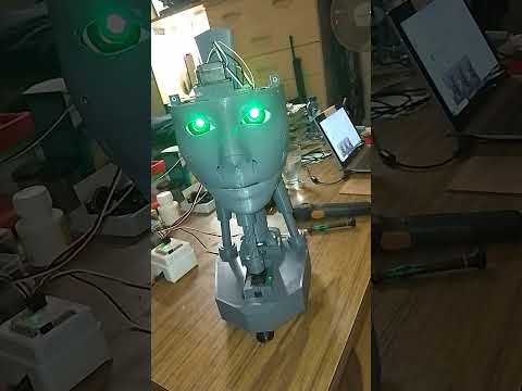
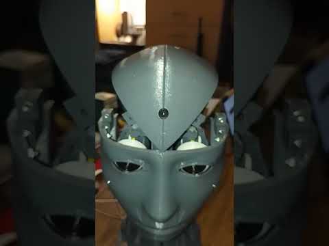
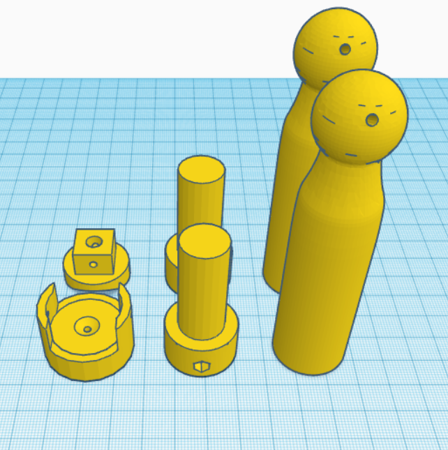
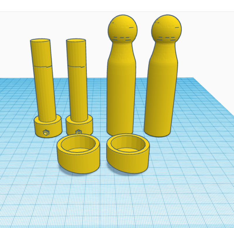
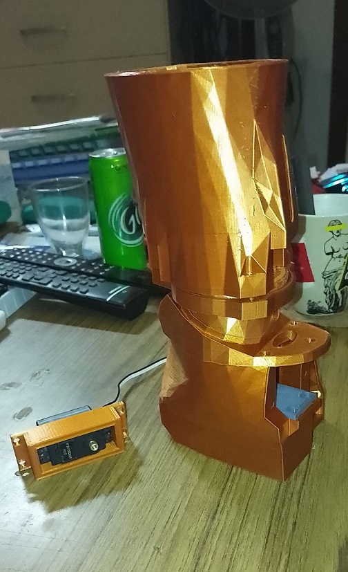
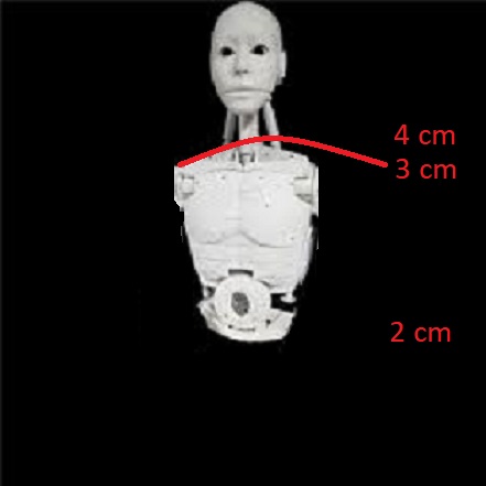
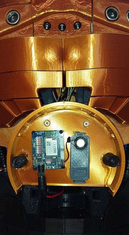
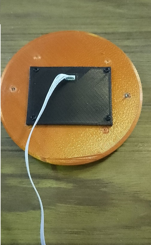
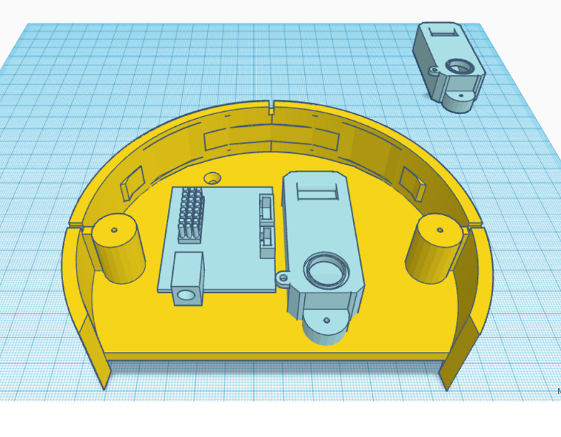
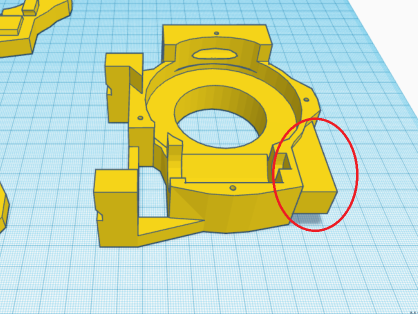
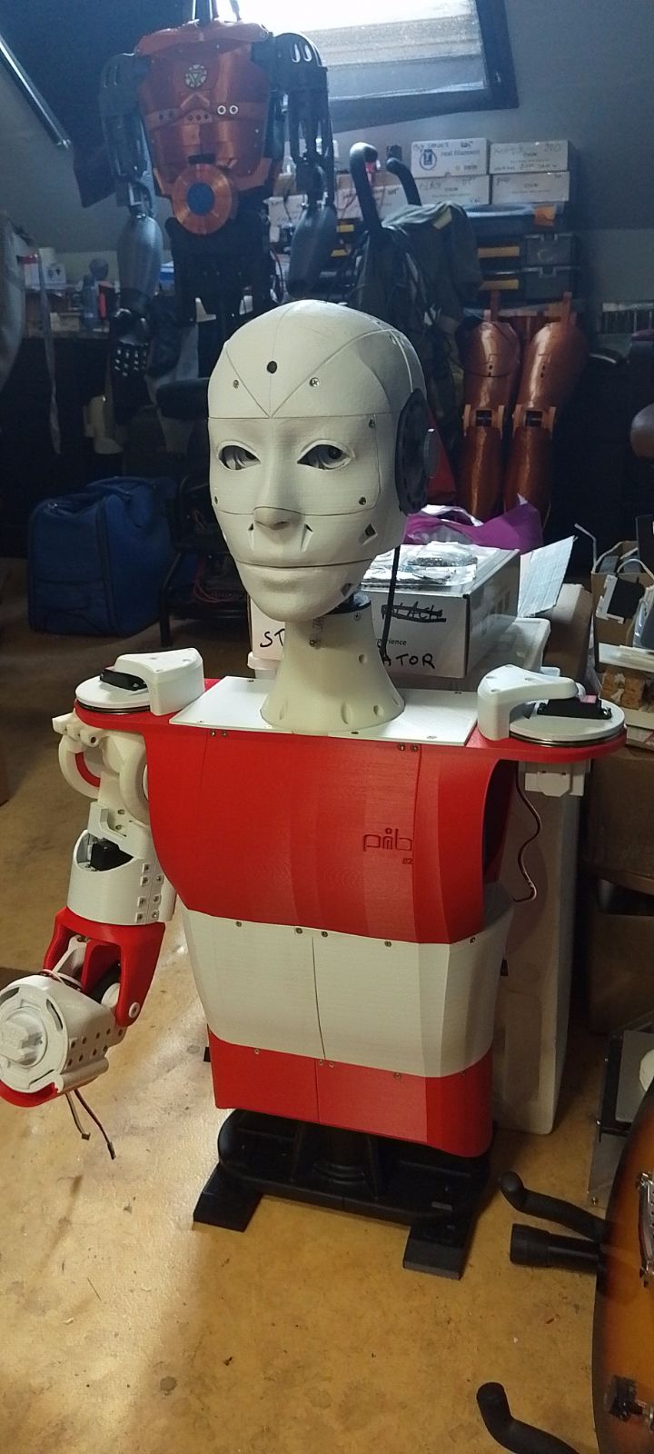
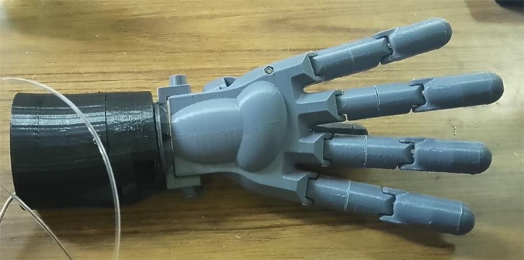
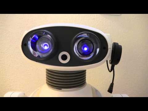
I've created a modified version of the EZ Robot head, featuring both side-to-side and up-and-down (yes) movements. This new design includes an improved base for the head, accommodating three additional HDD servos. There's an option to install two cameras, with the base designed to allow passage for a second camera cable. This setup is ideal for incorporating additional IoT devices or EZBV4, for instance, for LED lighting. Conveniently, there's no need to remove the potentiometer from a servo, as the 1 to 180-degree range provides ample movement. The base height is 7.2 cm.
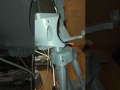
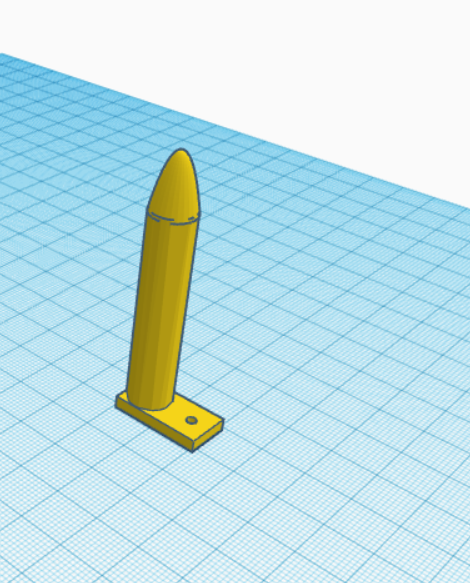
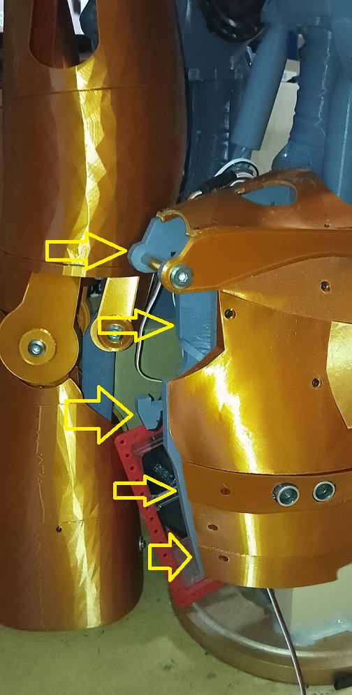
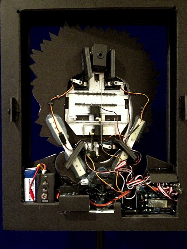
The pistons are original components from InMoov, and the neck base in EZ Robot is correctly designed.
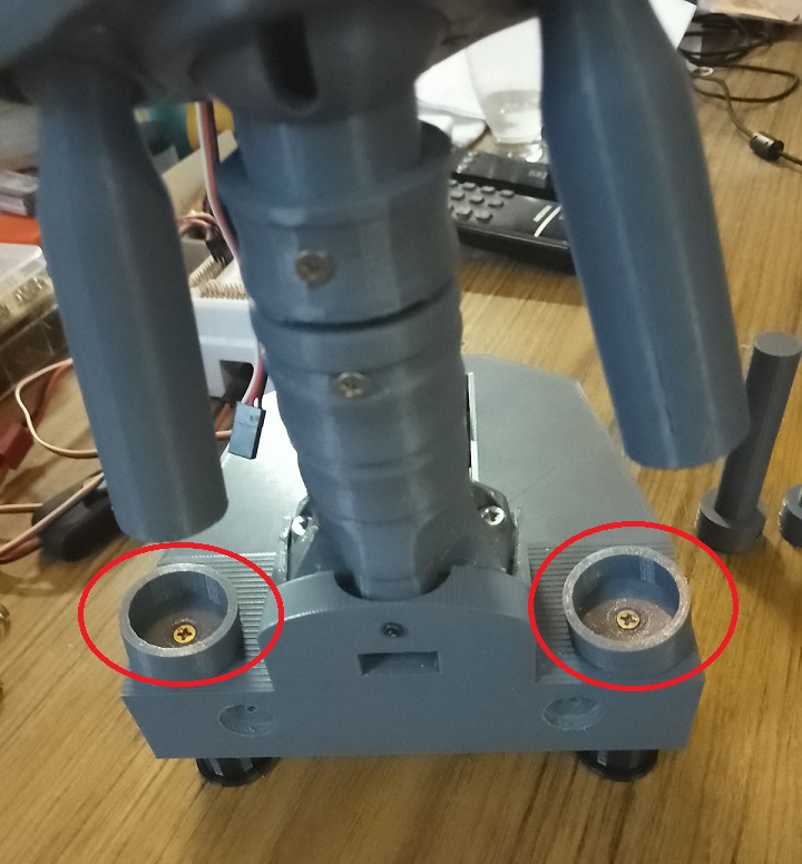
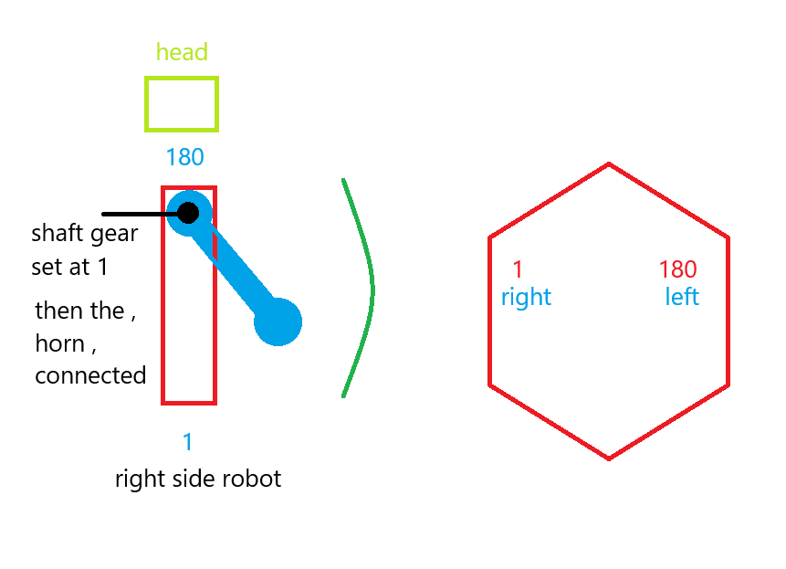
For moving the side pistons, adhere to these settings:
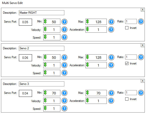
Programming
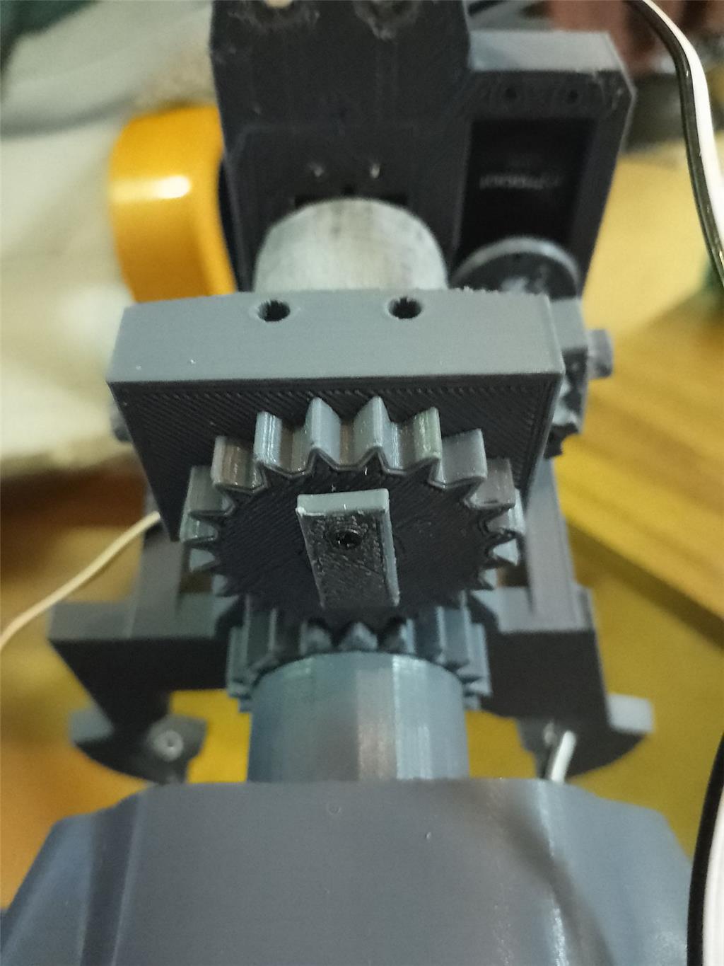
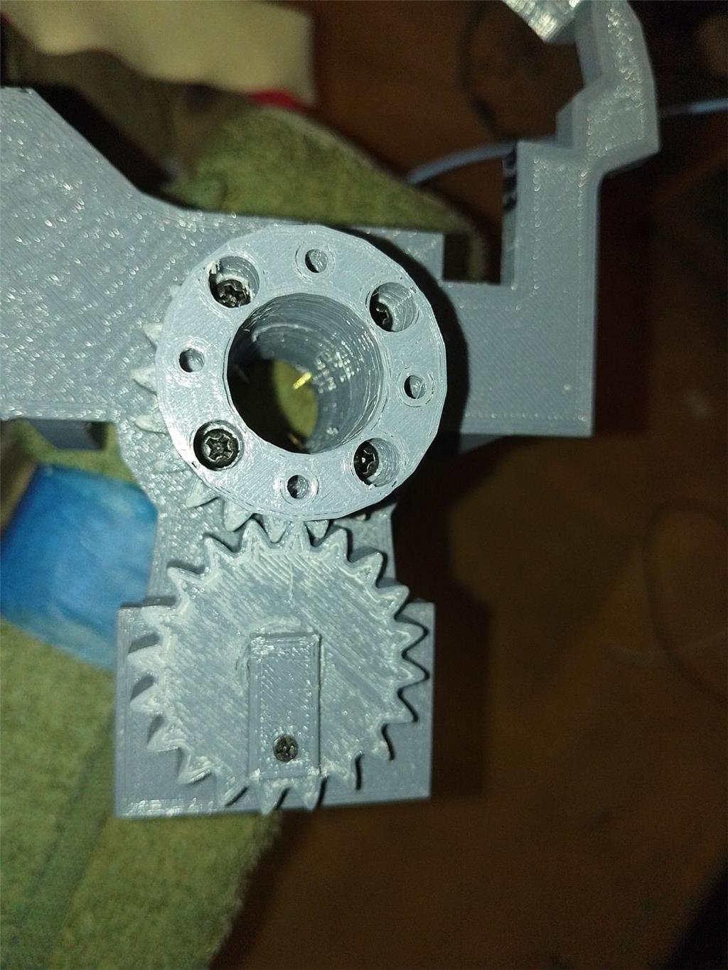
Adjusting the side pistons can be a bit complex. Start by calibrating your HDD servos. Then, align the inner piston with the holes in the piston base and secure it with a screw. For the second side piston, align it similarly, then disconnect the IoTiny. This allows you to manually adjust the previous piston to properly position the second one. The original documentation on EZ Robot is extremely helpful in this process.
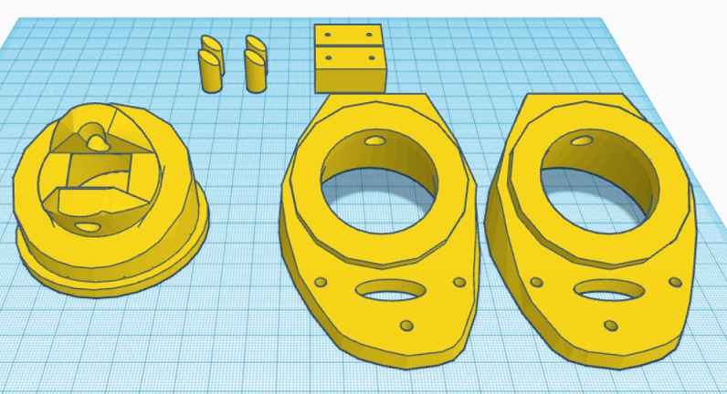
Parts & Materials
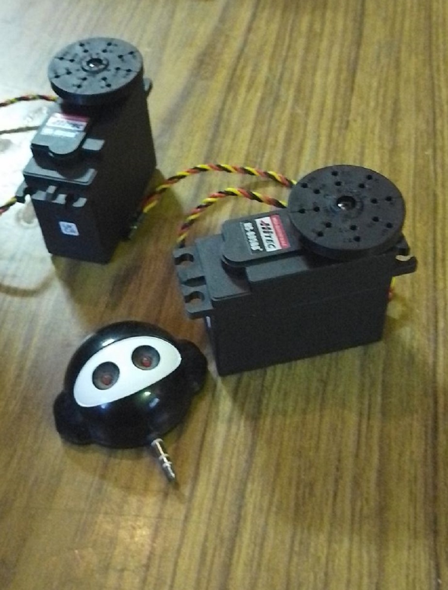
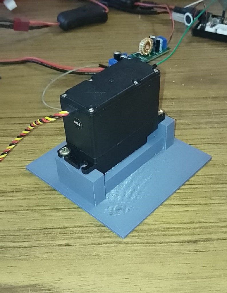
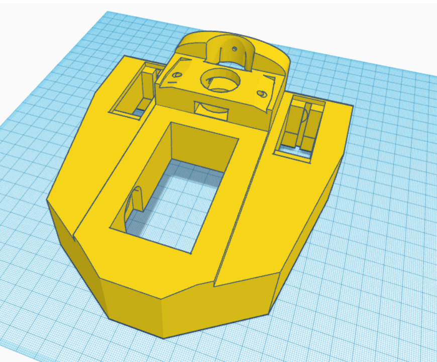
You'll need 3 extra HDD servos and grey PLA filament. The drive shaft parts should be printed with a 35% infill and a gyroid pattern in your slicer for enhanced strength. Other parts can be printed according to your preferences. Additionally, there's an optional neck extension, offering one to three extra vertebrae for more piston movement space. In my experience, the two-vertebrae option works best.
Discover more robots
Lizpoir's Omnibot 200 In Germany
Steve70x7's Robot Albert E

nink
i used just the horizontal window . nothing connected .
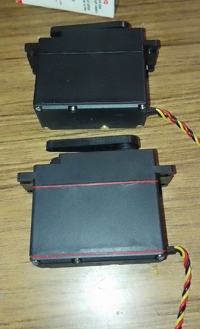
Oh dear bummer. So absolutely a servo problem unless you blasted 100v through the thing. Send them hate mail and ask them to send you another one.
problem solved . servo malfunction.
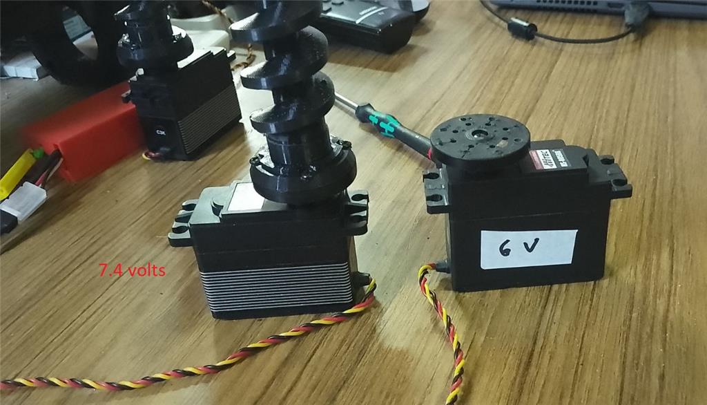
EDIT: I've since learned that 3 cell LiPo Batteries are 11.1V not 7.4V. You could have a 2 cell or 4 cell 7.4V LiPo battery but not a 3 cell. Thanks guys.
I don't understand what cell number has to do with anything but I don't know a lot about batteries. I do know that when you're matching a power source like a battery to a motor or device you need to be able to supply more amps then needed (overhead) and not more volts then what the device is rated for. Also DC motors can run on a lower voltage then they are rated for (within specs). Anyway. from what I know the amperage that a battery can supply and how long they can supply it depends on the cells and how they are wired. As long as you supply the motor with enough amps and not any more voltage then needed (or way to little) you should be good to go.
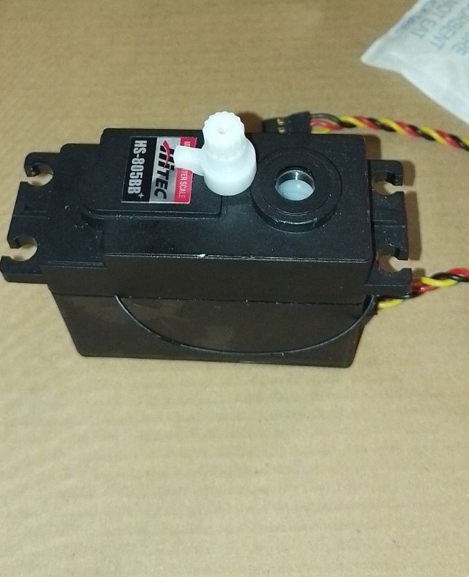
Sometimes a motor in a servo will just burn up. It happens. I just had to replace a $150 HiTec servo in my robot arm. It was mounted in a servo gearbox so there wasn't a ton of torque on it. It had been running just fine for a long time until one day while moving the little motor inside just got hot, puffed up and died. Same thing happened to a different lower cost HiTec servo mounted in a different gearbox in the arm a few months ago.
After reading through a lot of RC (Airplane and car) forums on this subject saw a lot of posts that say HiTec servos can take up to 8 volts. There was also a lot of talk of servo failure rates. Some HiTec servos fail more then others. HiTec seems to discontinue thoues. My higher priced HiTec servo I mentioned above that burnt up has been discontinued.
Again, I'm no expert, just speaking from experience and what I've learned from others. Take my words with a grain of salt. LOL.
Keep up the good work and have fun!!!
2 cell is 7.4v but fully charged and put out as much as 8.3v 3 cell is 11.1v but fully charged about 12.45v.
so if you slam 12v in a servo expecting 7.4v things are going to get a little Smokey.
hi averyone
dave thank you for your opinion . it says allot .
nink
also thank you
dj looked at it and my batt was good . 2 cell 7.4 volts .
hi averyone
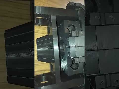
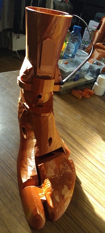
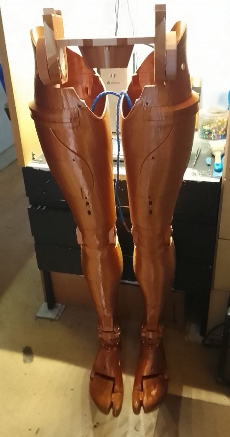
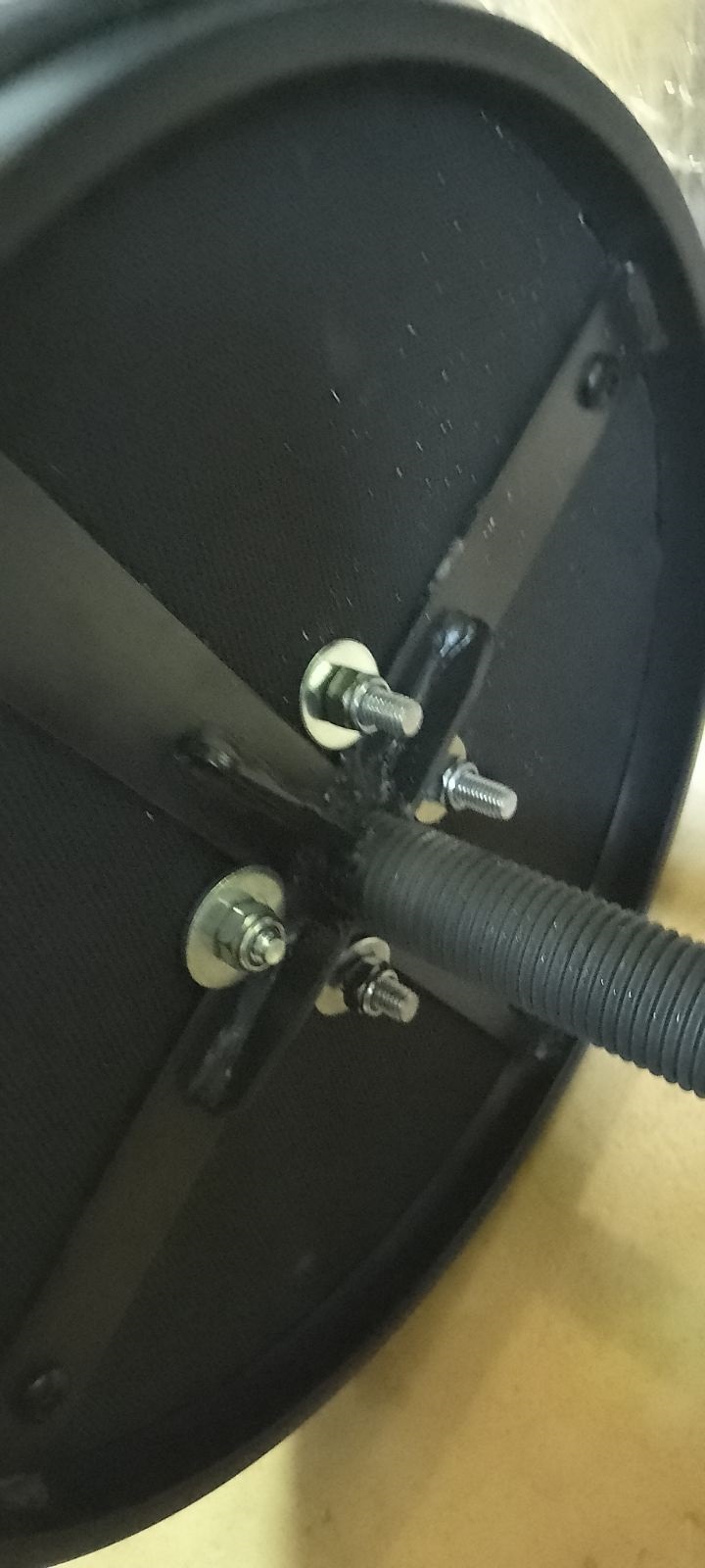
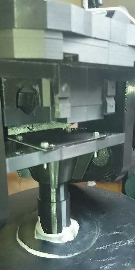
some times you have to print a part to understand why the designer made it that way . the botem plate for the inmoove butt has tapered corners . cause of the front covers . so i made that part so you can use locknut and screws M4 to make a strong bond .
a little video about that .
https://www.youtube.com/shorts/Nz96RGGmDFE
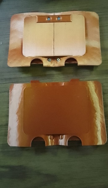
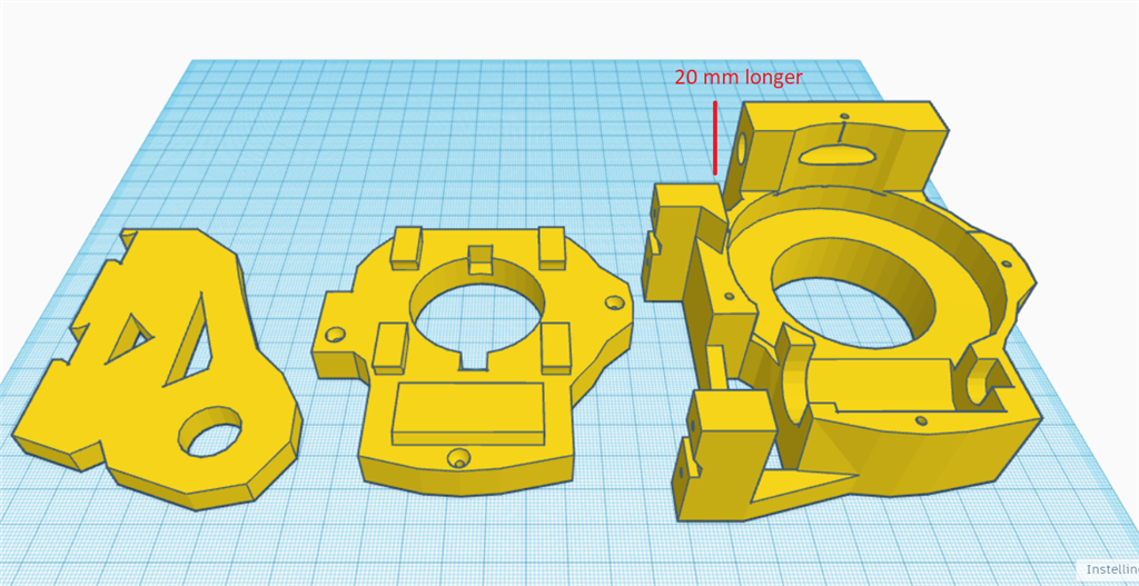
i also extended the side panels to be able to mount a metal plate ontop so the pole, you are using doesn get thru all the way to far .
baseCLOSE.stlRlongside.stlLeftlongside.stl
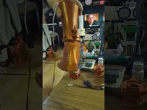
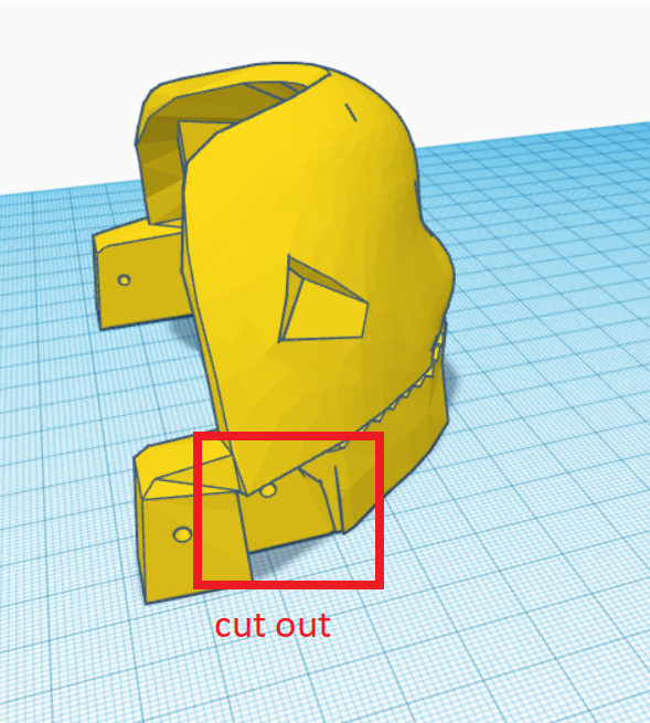
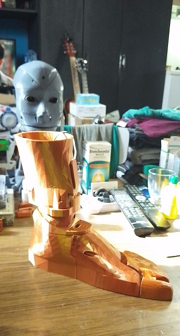
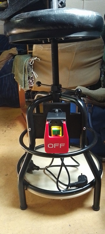
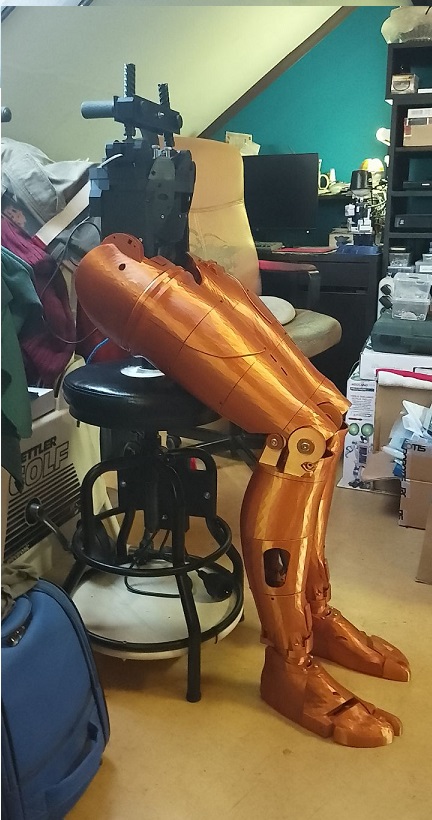
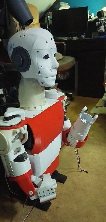
hi all
the final hip is reddy . longer side parts . files from post #55 here a little video how it looks .