


hi all
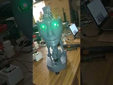
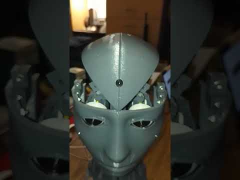
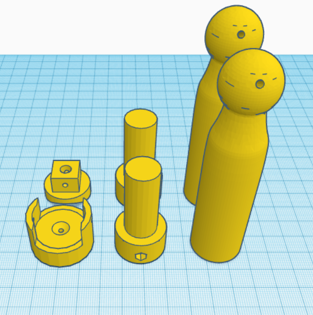
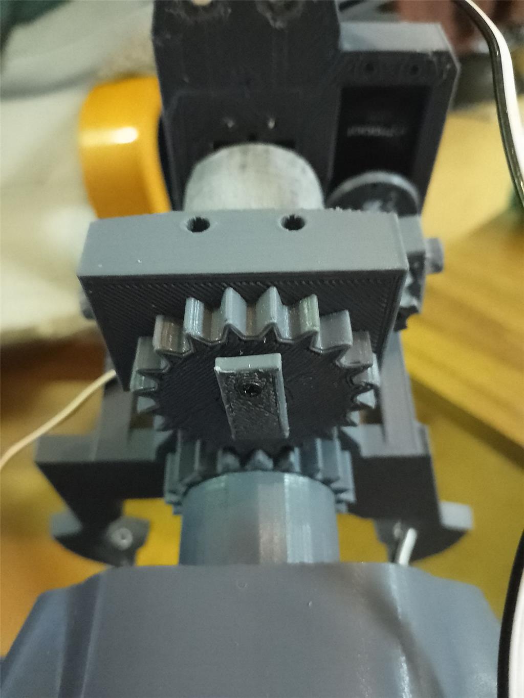
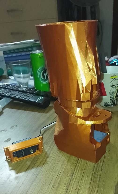
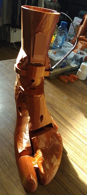
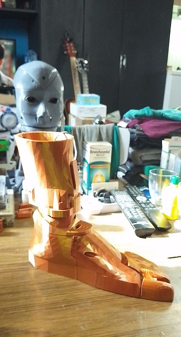
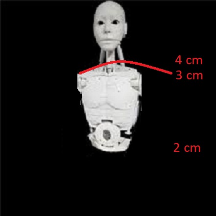
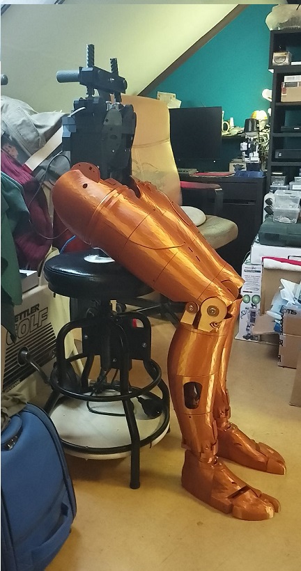
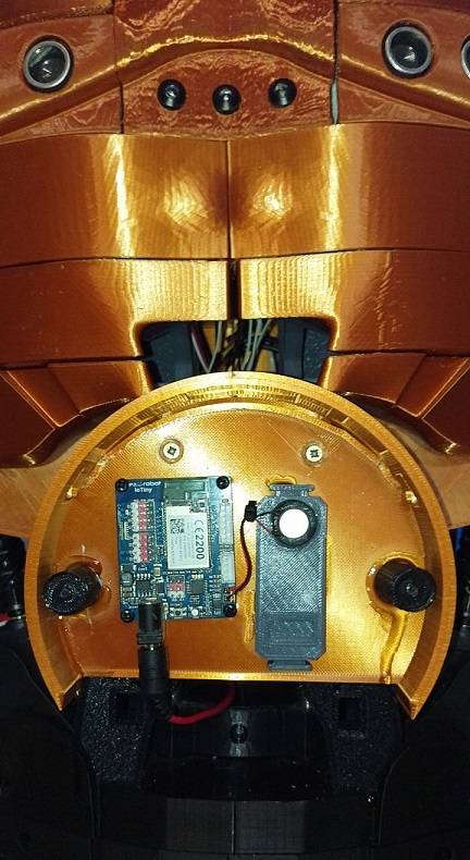
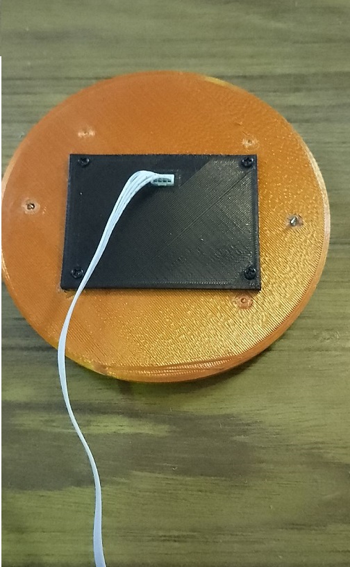
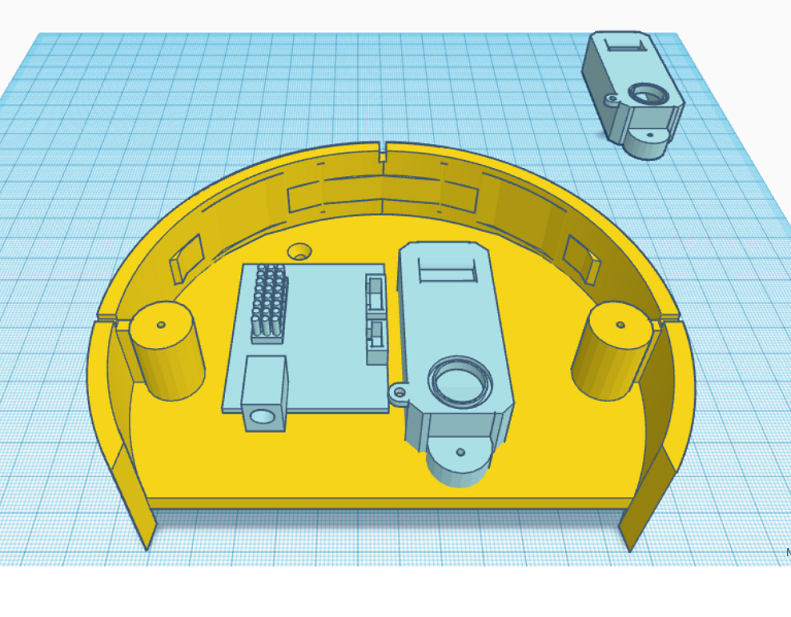
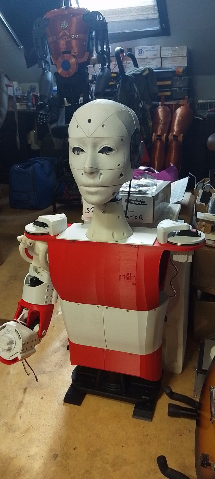
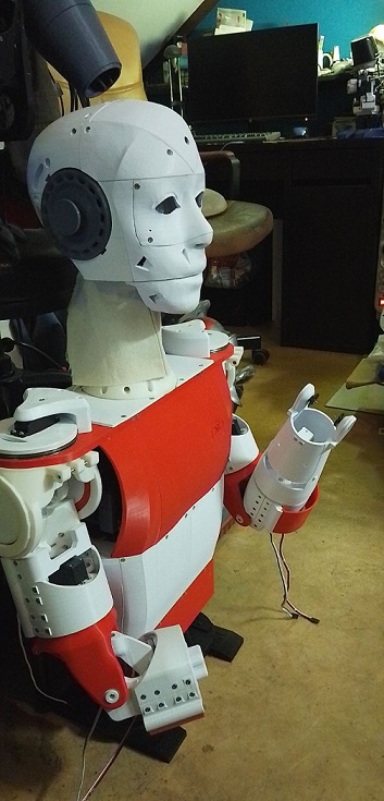
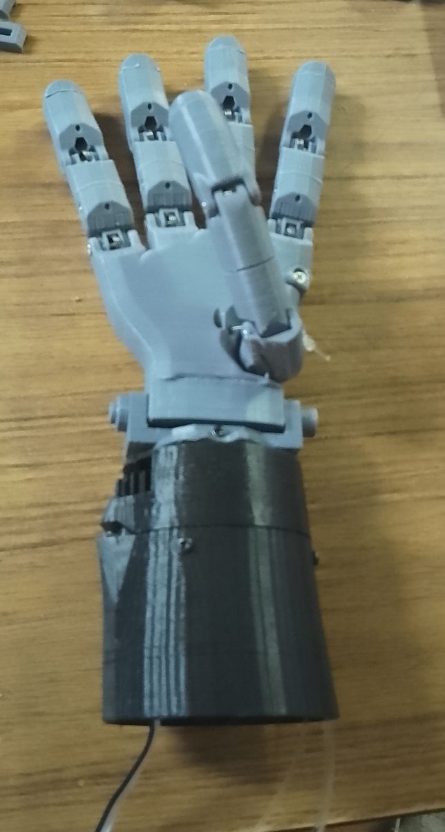
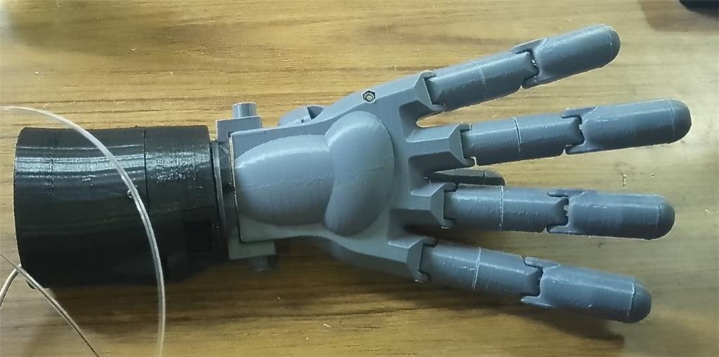
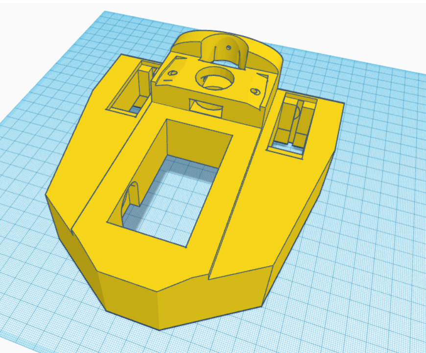
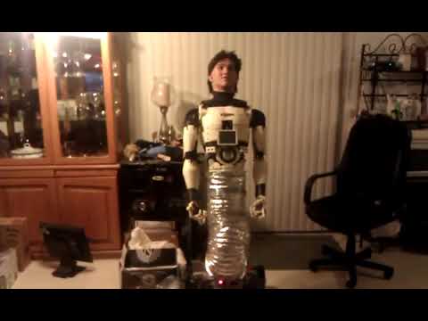
I've created a modified version of the EZ Robot head, featuring both side-to-side and up-and-down (yes) movements. This new design includes an improved base for the head, accommodating three additional HDD servos. There's an option to install two cameras, with the base designed to allow passage for a second camera cable. This setup is ideal for incorporating additional IoT devices or EZBV4, for instance, for LED lighting. Conveniently, there's no need to remove the potentiometer from a servo, as the 1 to 180-degree range provides ample movement. The base height is 7.2 cm.
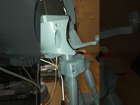
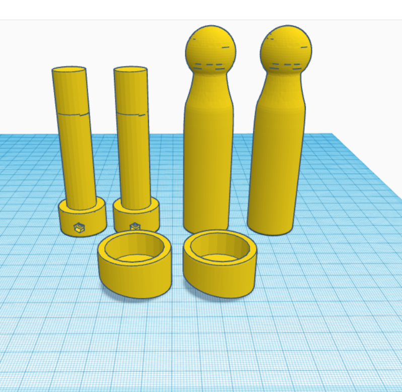
The pistons are original components from InMoov, and the neck base in EZ Robot is correctly designed.
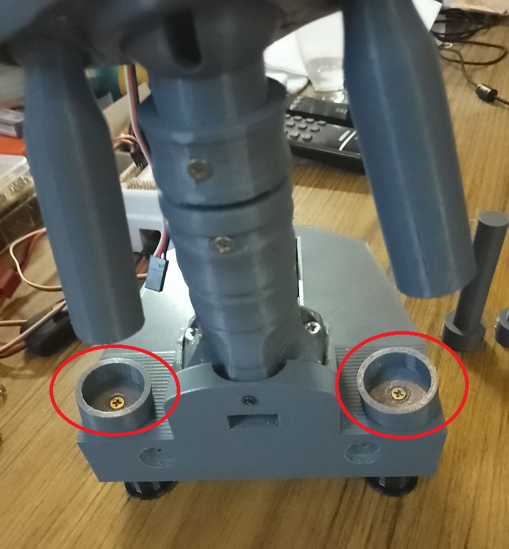
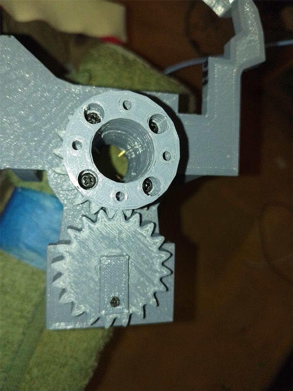
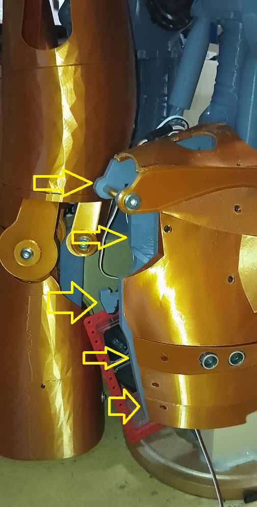
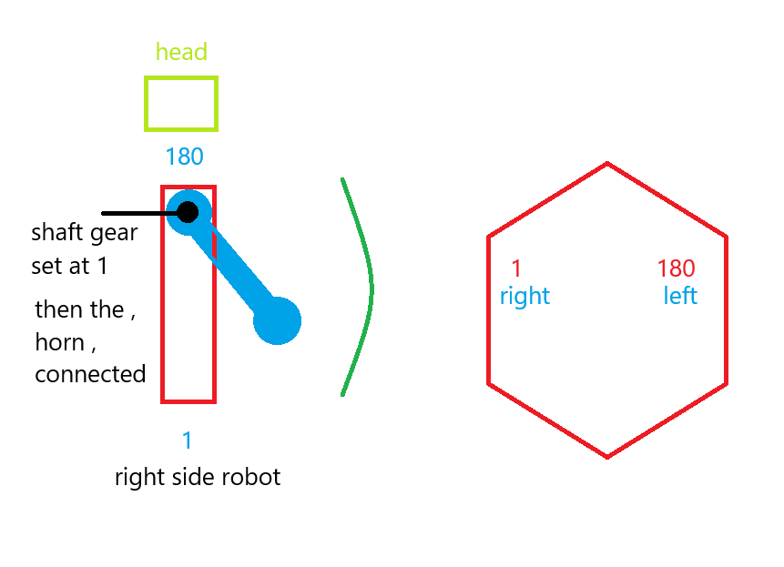
For moving the side pistons, adhere to these settings:
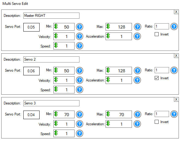
Programming
Adjusting the side pistons can be a bit complex. Start by calibrating your HDD servos. Then, align the inner piston with the holes in the piston base and secure it with a screw. For the second side piston, align it similarly, then disconnect the IoTiny. This allows you to manually adjust the previous piston to properly position the second one. The original documentation on EZ Robot is extremely helpful in this process.
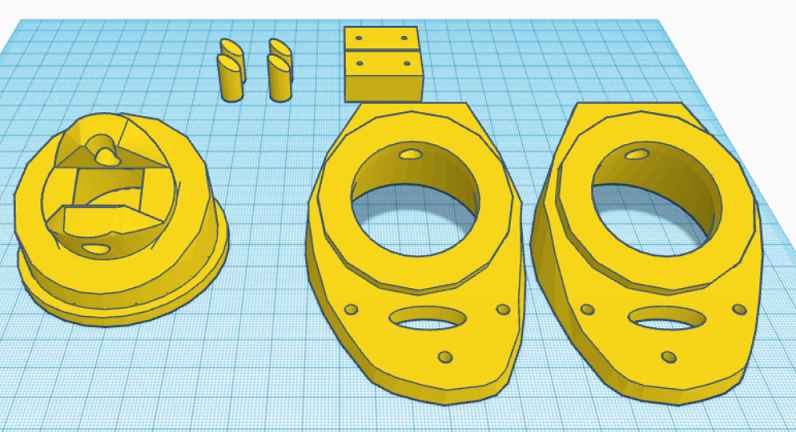
Parts & Materials
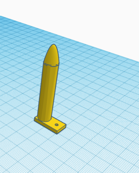
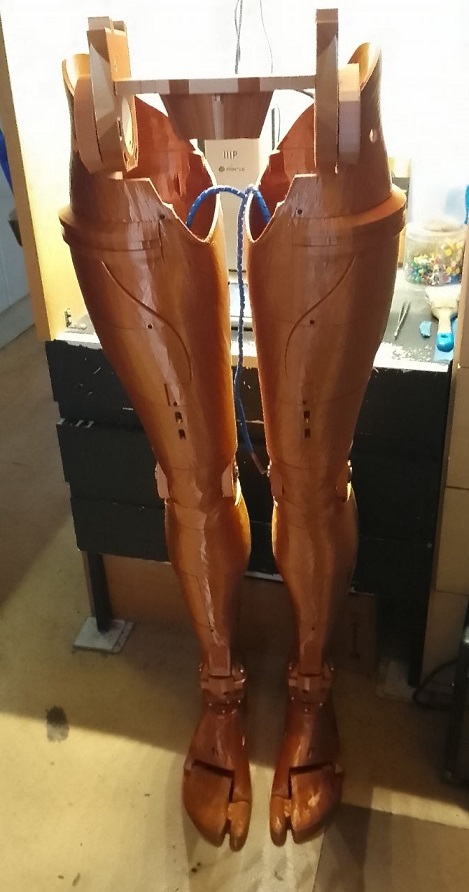
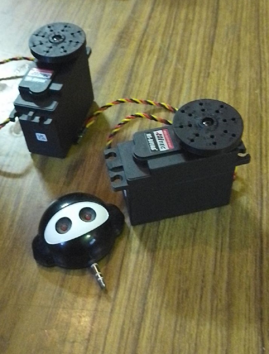
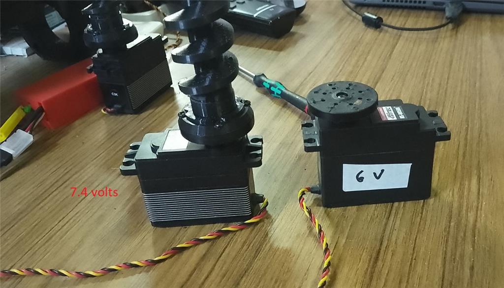
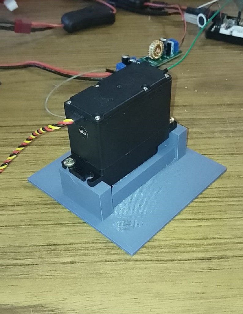
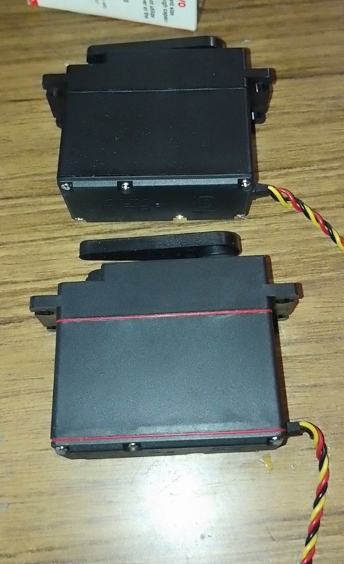
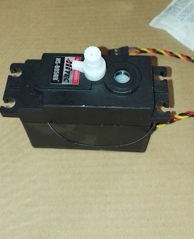
You'll need 3 extra HDD servos and grey PLA filament. The drive shaft parts should be printed with a 35% infill and a gyroid pattern in your slicer for enhanced strength. Other parts can be printed according to your preferences. Additionally, there's an optional neck extension, offering one to three extra vertebrae for more piston movement space. In my experience, the two-vertebrae option works best.
Discover more robots
Redzone's Gideon Inmoov
Ezang's ESP32 And ARC - Arduino And PCA 9685

hi dave
especially when its repetitive work .
the inmoov kit is awesome but there are some flaws in it .
here is one
https://www.youtube.com/shorts/CWZRAYnz90Q
@nomad, you're doing a really great job. You have more determination than I do. i could not make an inmoov. It's good watching your progress.
hi dj
thanks for the kind words .
hi
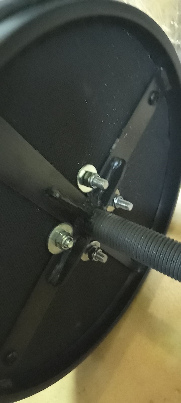
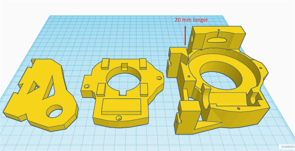
my solution for the shoulder touching . it took 3 times and then it hit me how to do it . make the main connection longer about 20 mm .
a short video.
https://www.youtube.com/watch?v=hZvSzBDTLCc
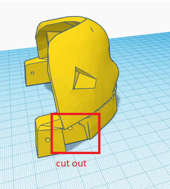
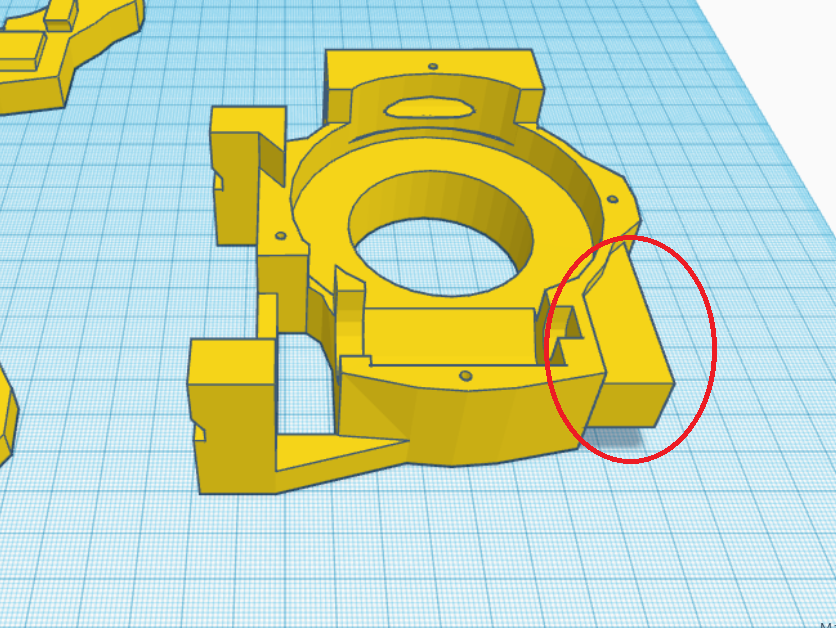
Instead of having the shoulder sticking out farther then the one on the other side, could you design and print a new part with a little indent or notch so it won't hit the body? alternately, could you simply just file down or sand down the area that hits the body?
hi dave
i have added a little stopblock so it cant go in the body . i reduced the outwart to 10 mm . i also use these bolts . they carry the hole arm perfect instead a bolt cause the treath , wil damage the shoulder hole and worn it out .there's a chance i test prunt one , whit just the stopper as you mention . sounds a good idea.
bolts longer
https://www.amazon.nl/Roestvrij-Klinknagel-Connector-Gezamenlijke-Moer-M8-60mm/dp/B0CGR7GW6G?pd_rd_w=BpJf6&content-id=amzn1.sym.402358f9-6ae7-49a1-a41b-aa7d8d607531&pf_rd_p=402358f9-6ae7-49a1-a41b-aa7d8d607531&pf_rd_r=4C758QR47EVFR3N3W0CS&pd_rd_wg=Qr3iv&pd_rd_r=d8673ec5-185b-4499-894a-b1b2e2b0cdf2&pd_rd_i=B0CGR7GW6G&psc=1&ref_=pd_bap_d_grid_rp_0_2_t
hi cool
one part reddy . the shoulder part . the stopper is inplace .
little video.
https://www.youtube.com/shorts/EZhsuZILXCU
hi
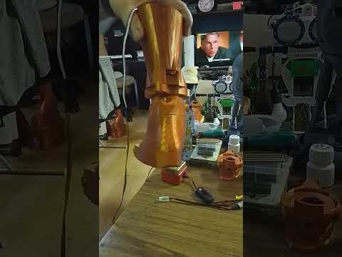
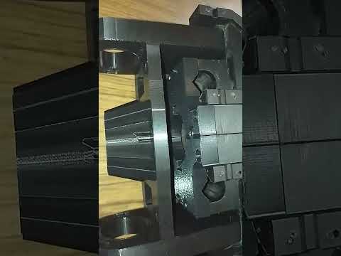
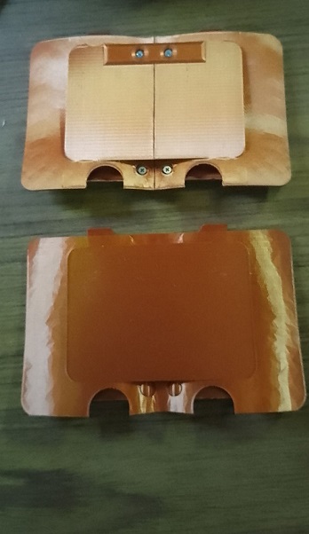
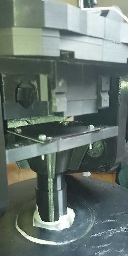
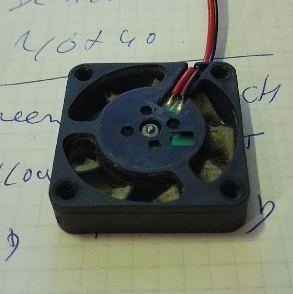
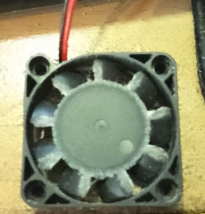
some fan errors detected . fan that hit the housing . cause plastik to thin . or 1 mm to short . the axel comes loose and so comes the fan hit the housing . this was a new fan , it got this problem from the start . i replaced with a new one . i notest the golden 1 MM , is many times the problem . picture . the middel of the fan is bend inwarts .that makes , the axel comes out the case and also the fan itself and hit the housing of the printer .
all the blades are worn out .