


cE9s4PsOgeBQIORwjd5!~~60_1-634818020230156250.jpg)


BO)Lupuc4g~~60_35-634706297915000000.jpg)
LupbT6!~~60_35-634706298769375000.jpg)


C5j!~~60_35-634655044863125000.jpg)


C5j!~~60_35-634659603510781250.jpg)


C5j!~~60_35-634651704046230469.jpg)
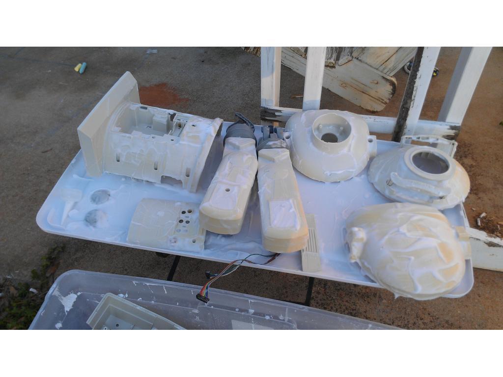
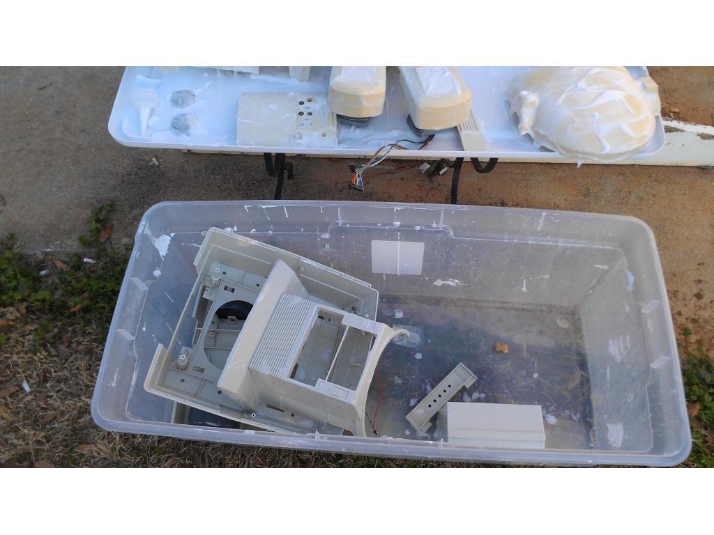
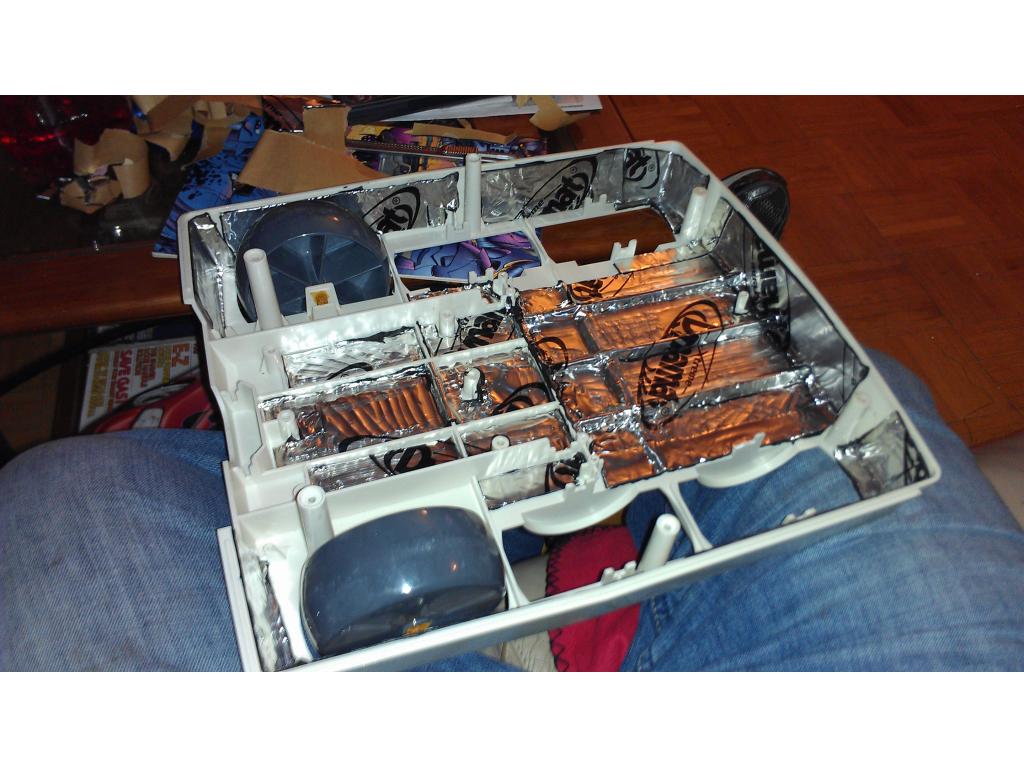
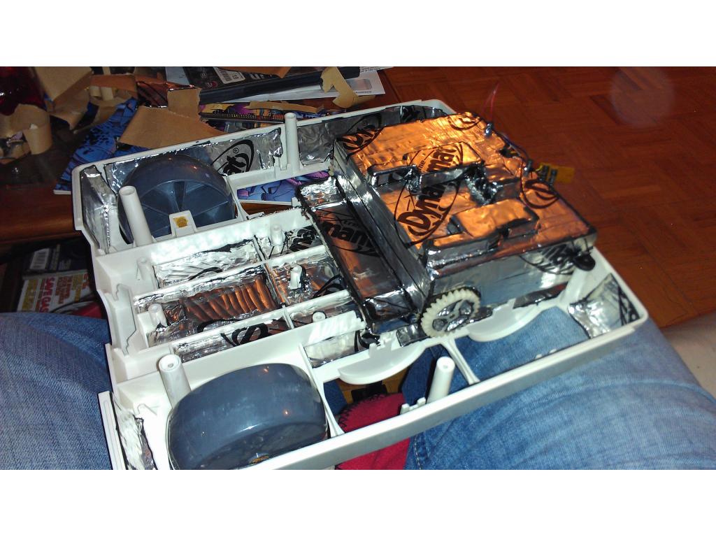
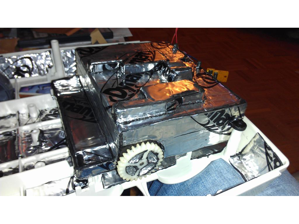


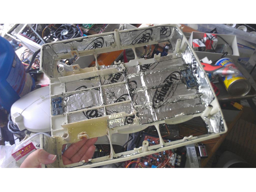


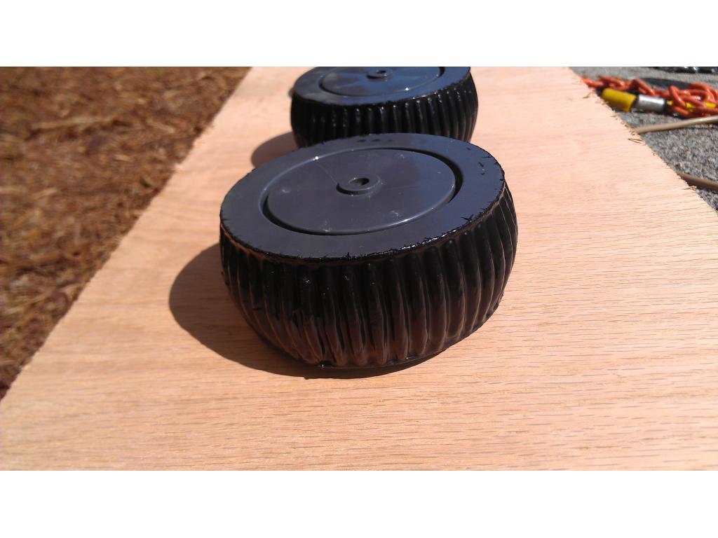

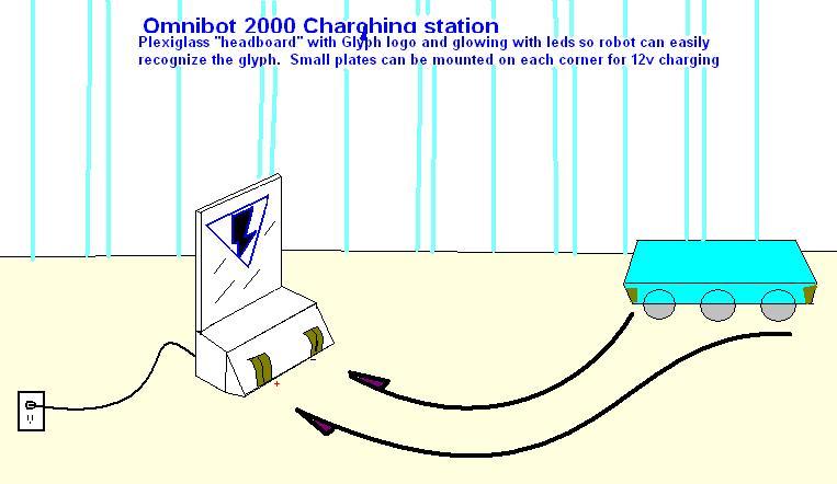
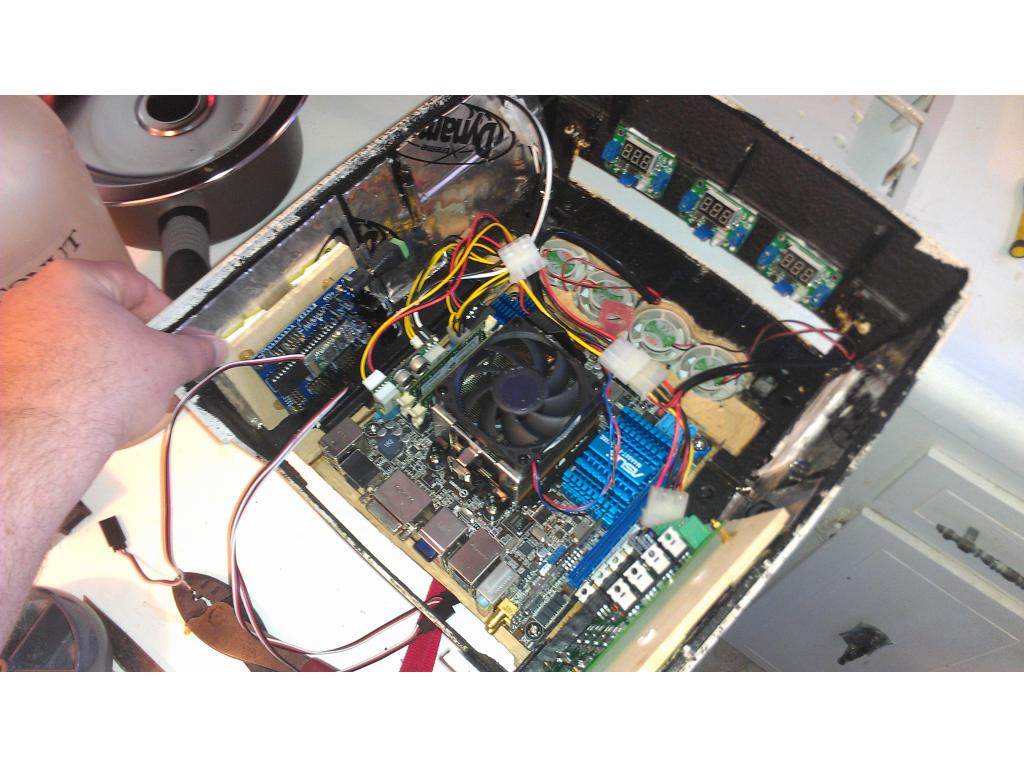


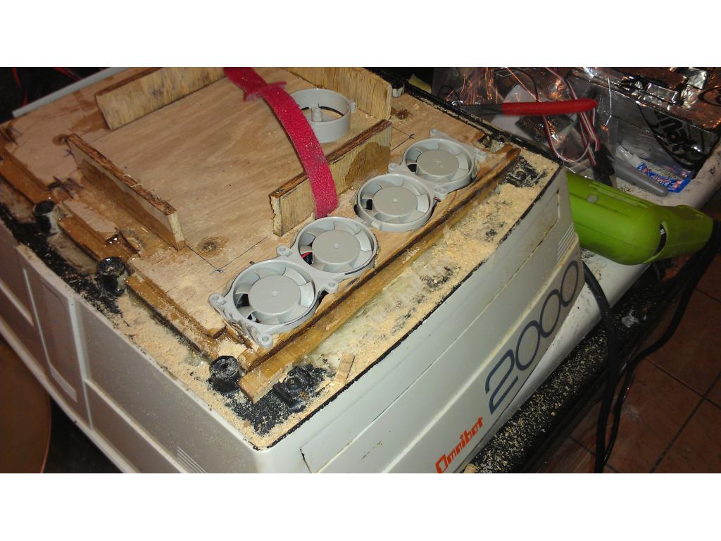
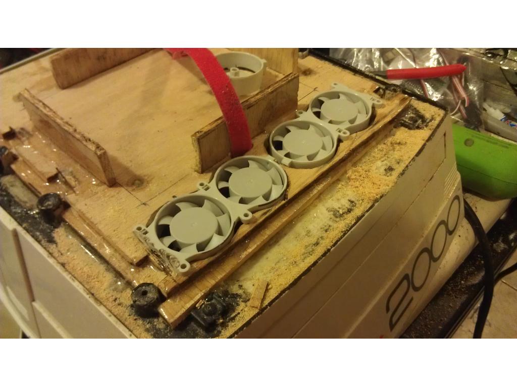

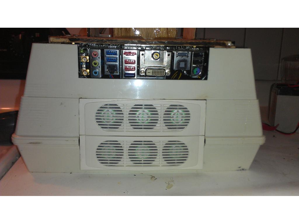


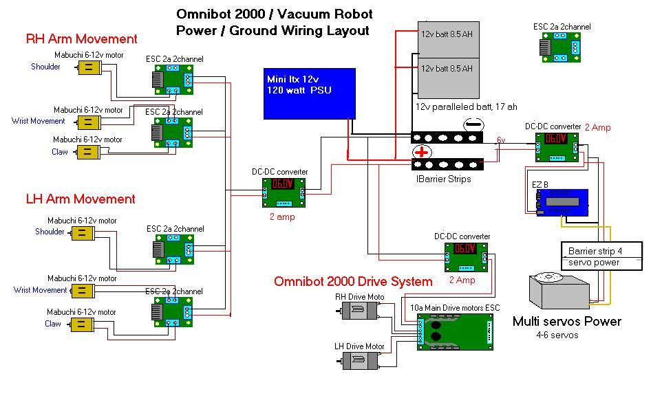

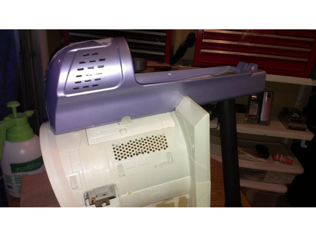
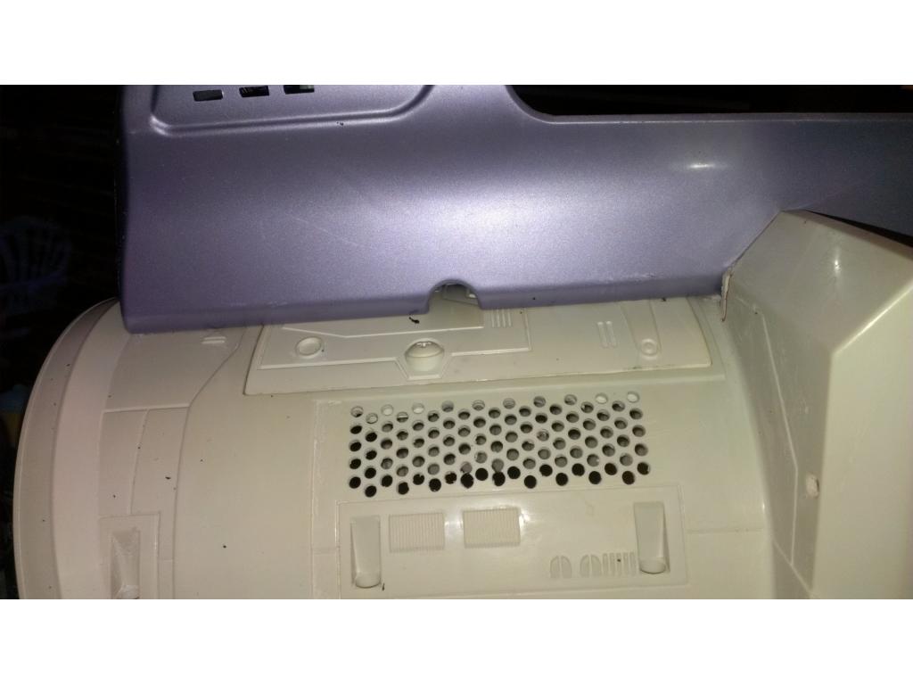
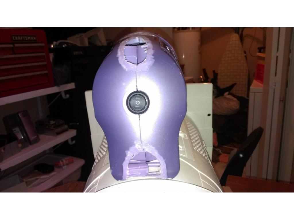
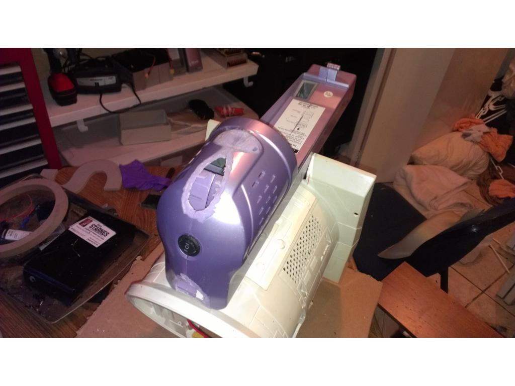

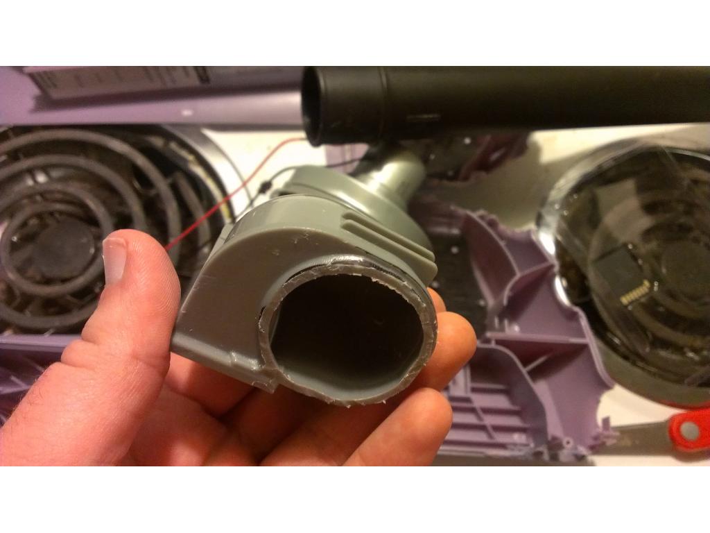
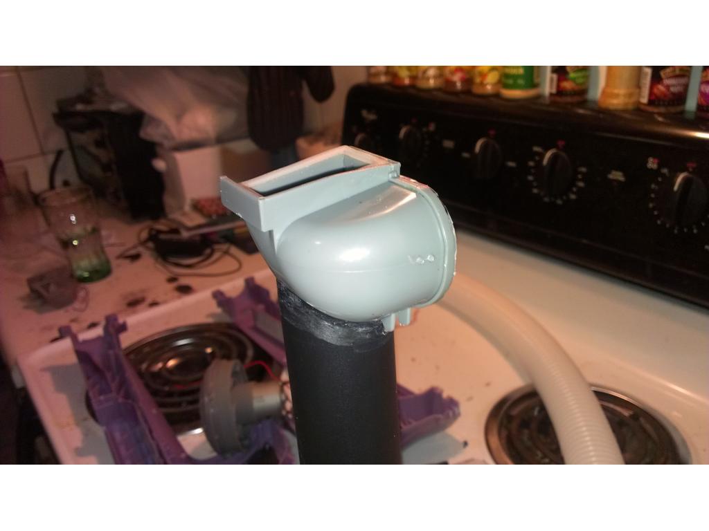
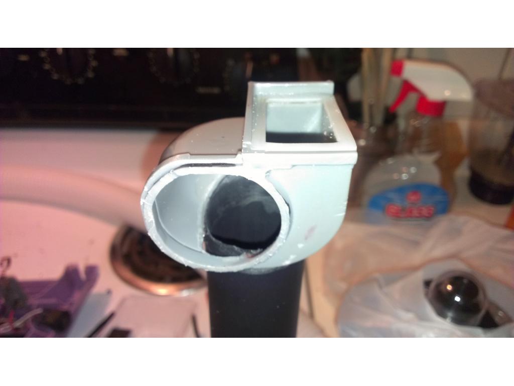
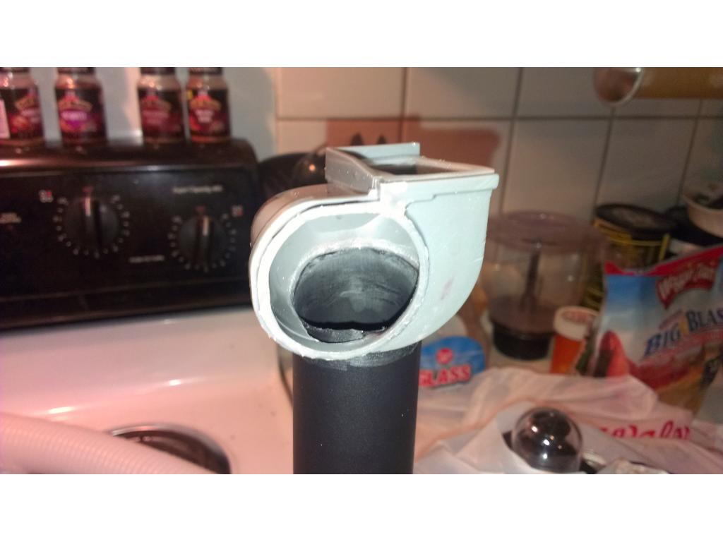
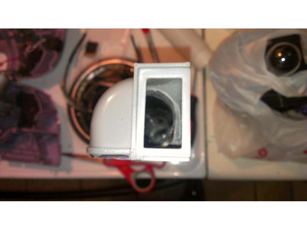
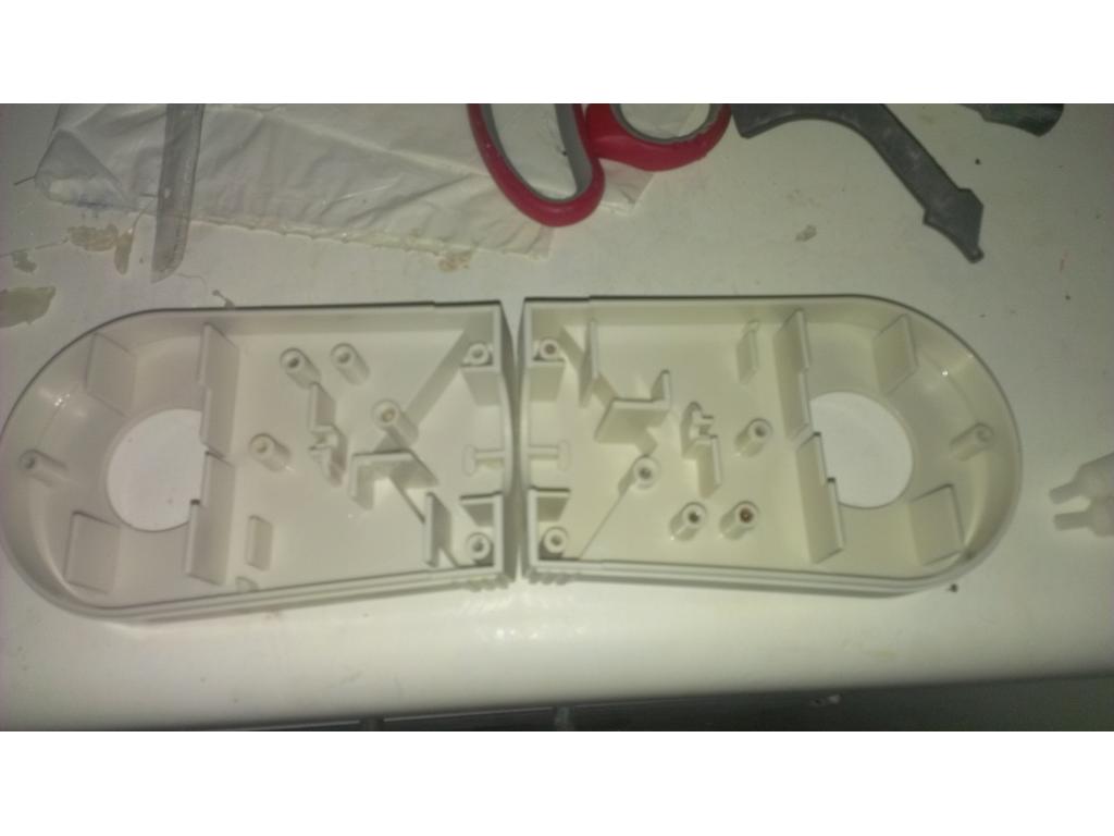

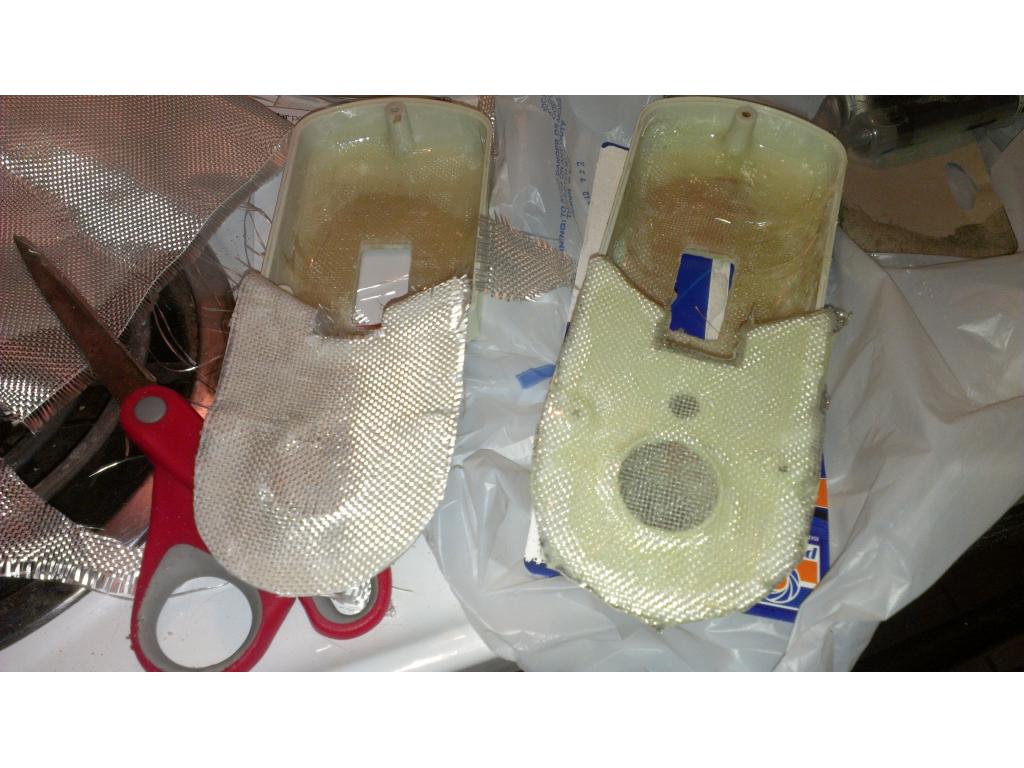

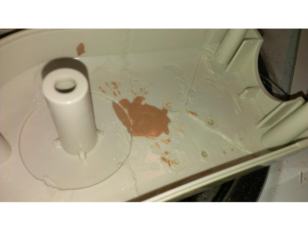
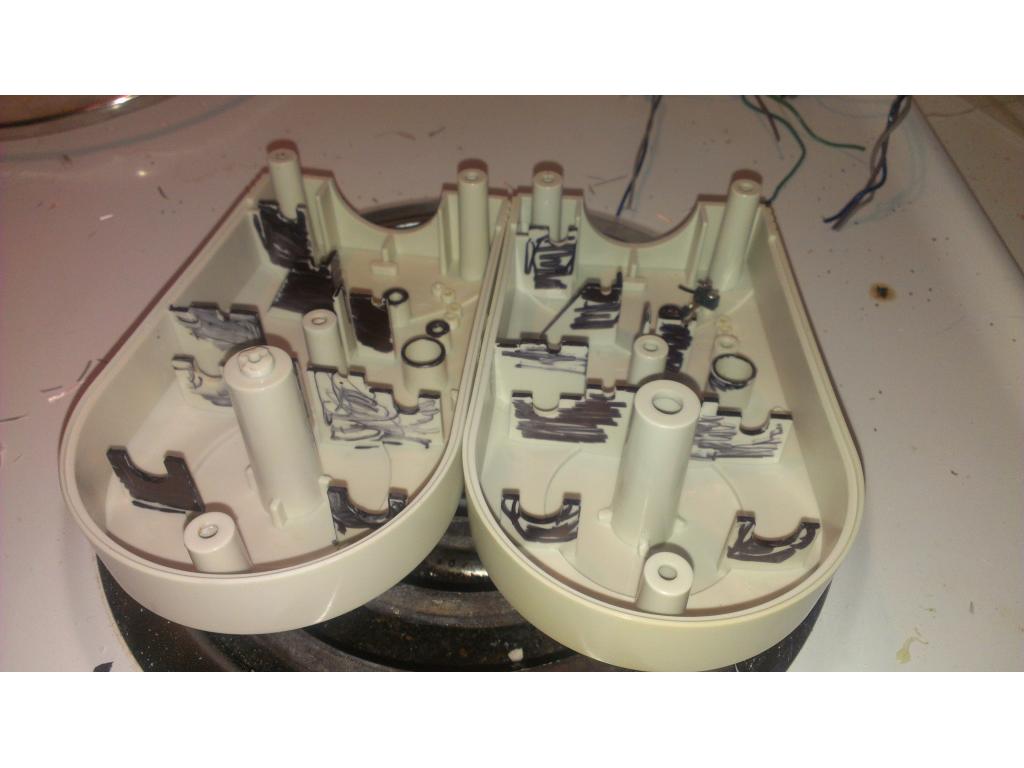
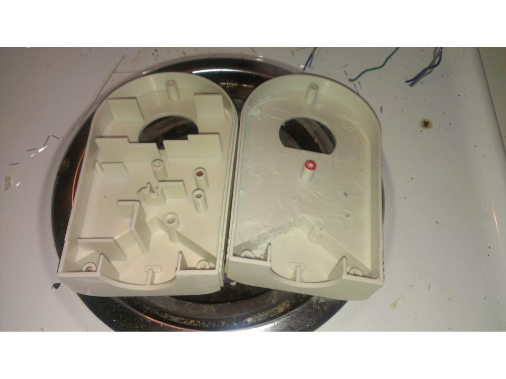
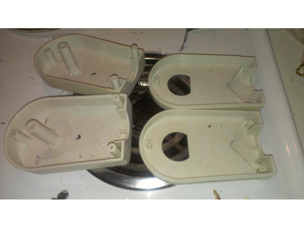
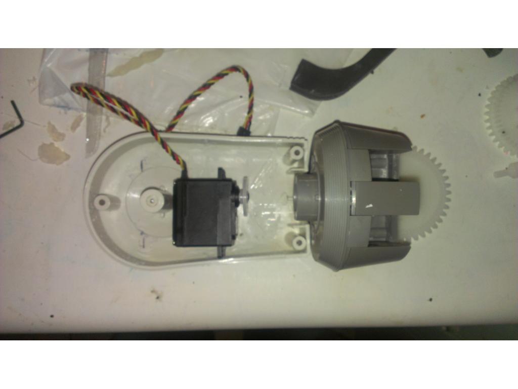
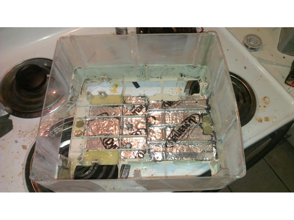

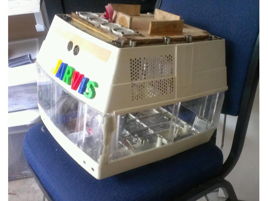
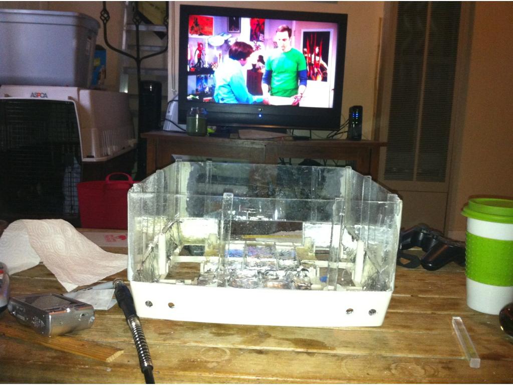
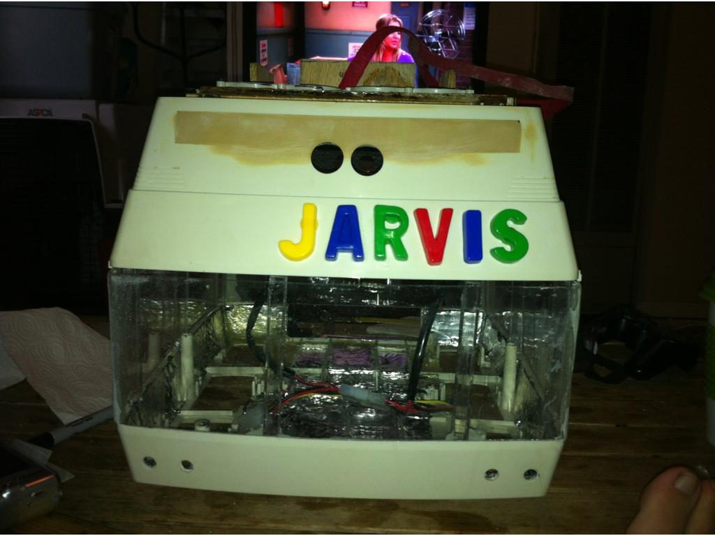
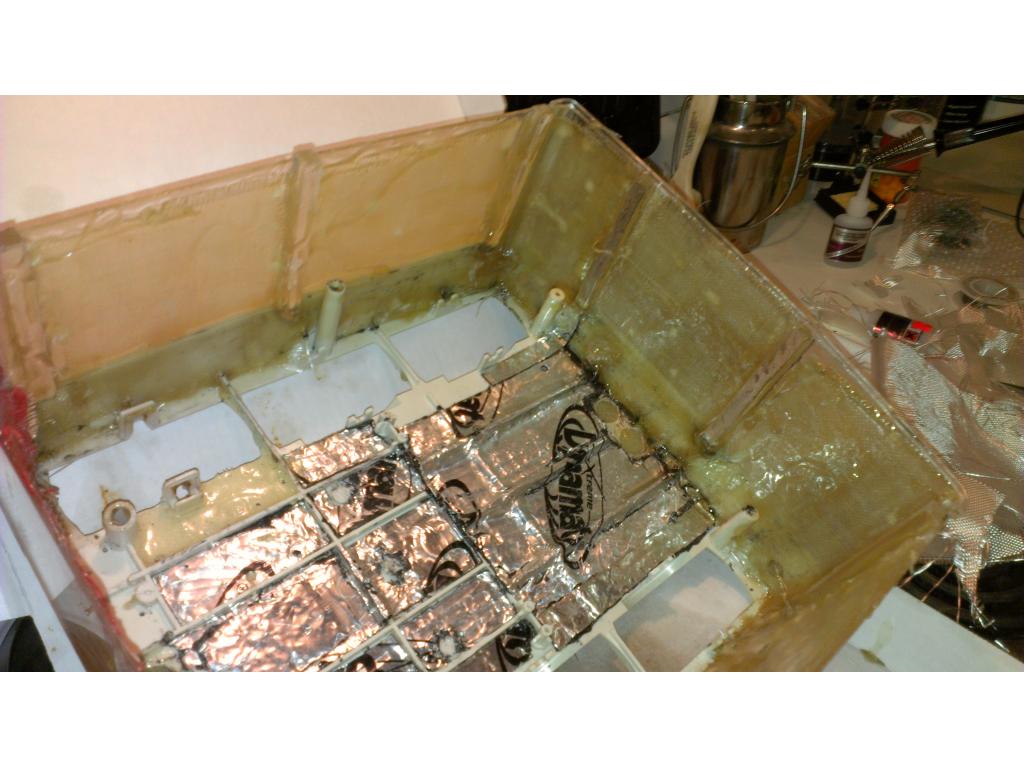
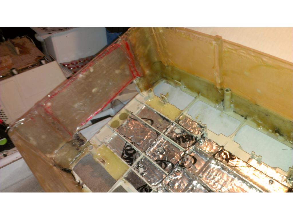
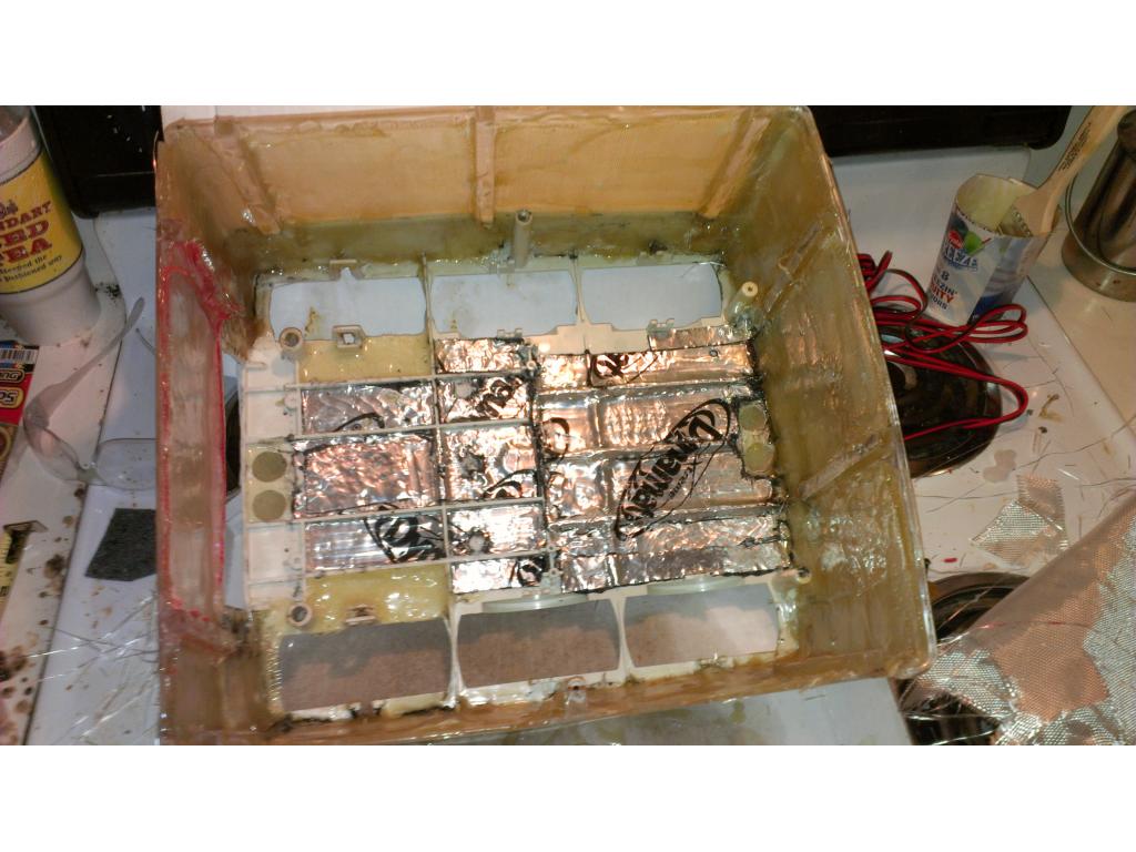


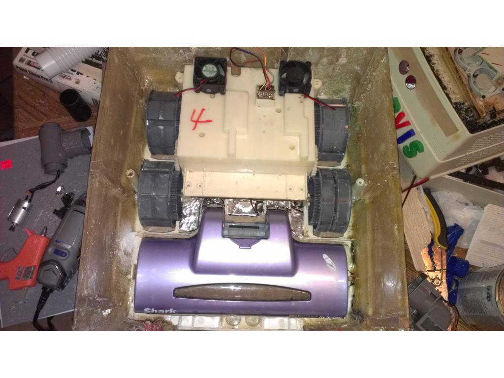
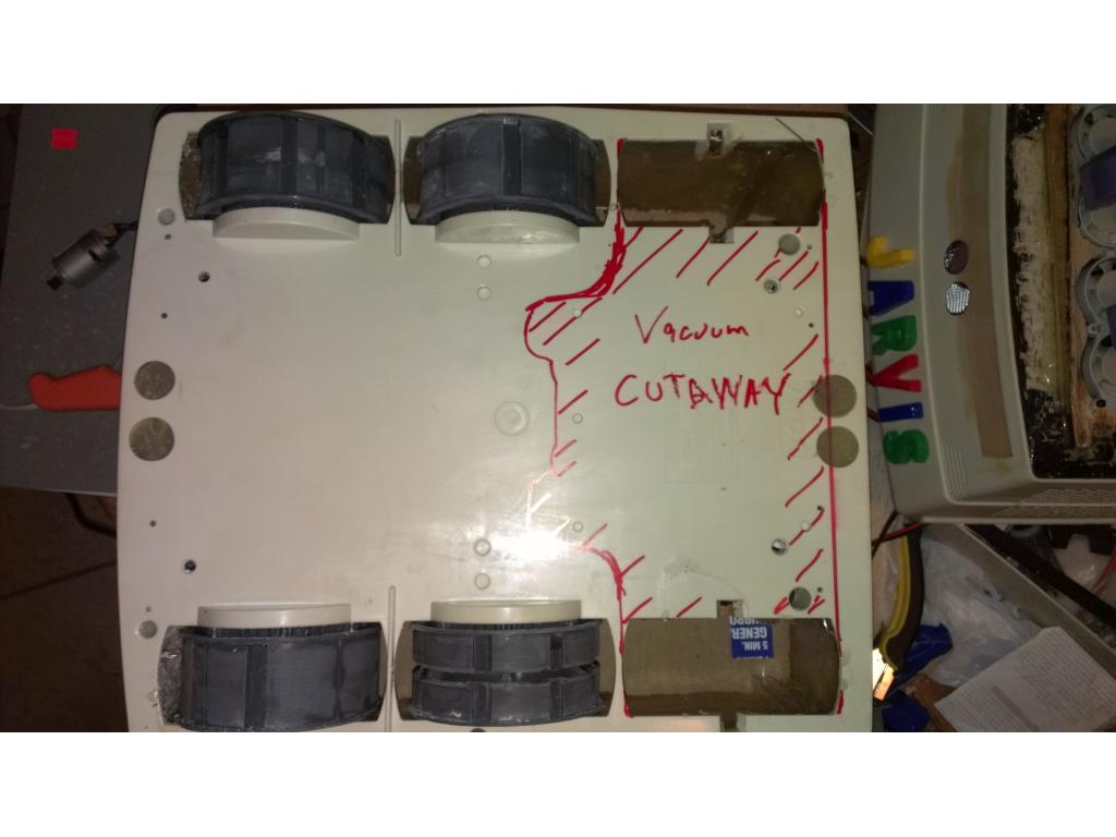
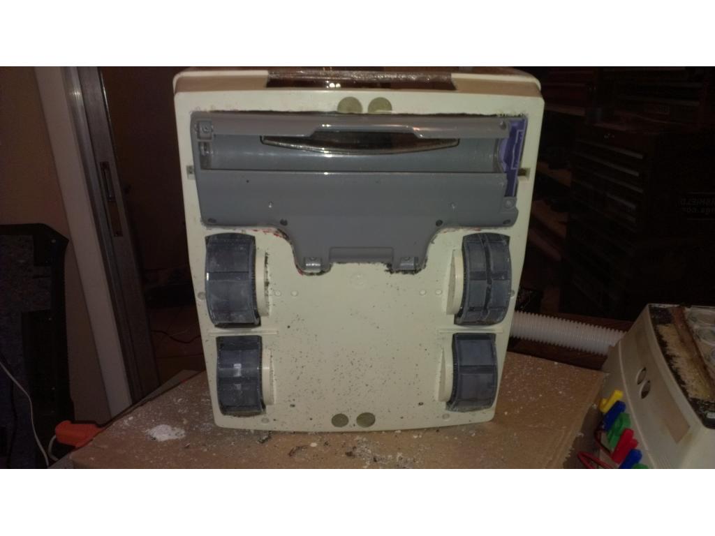
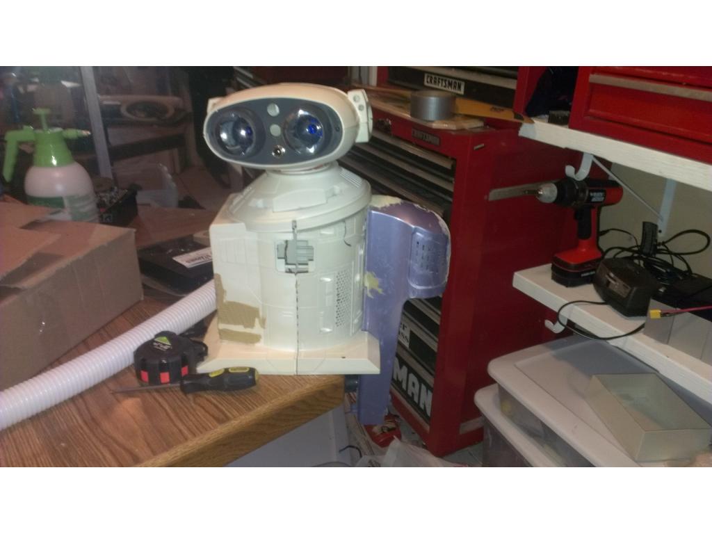
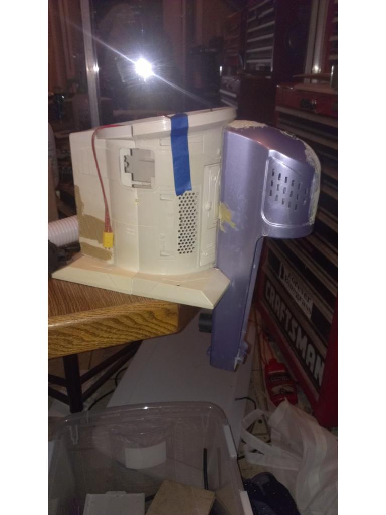

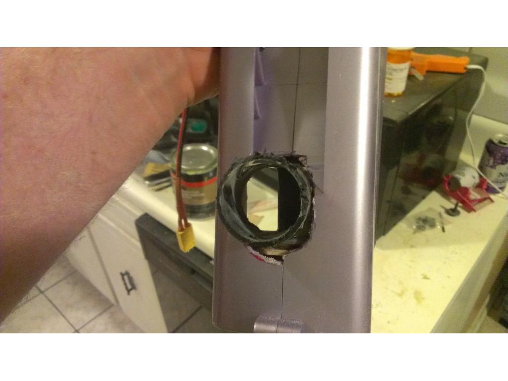


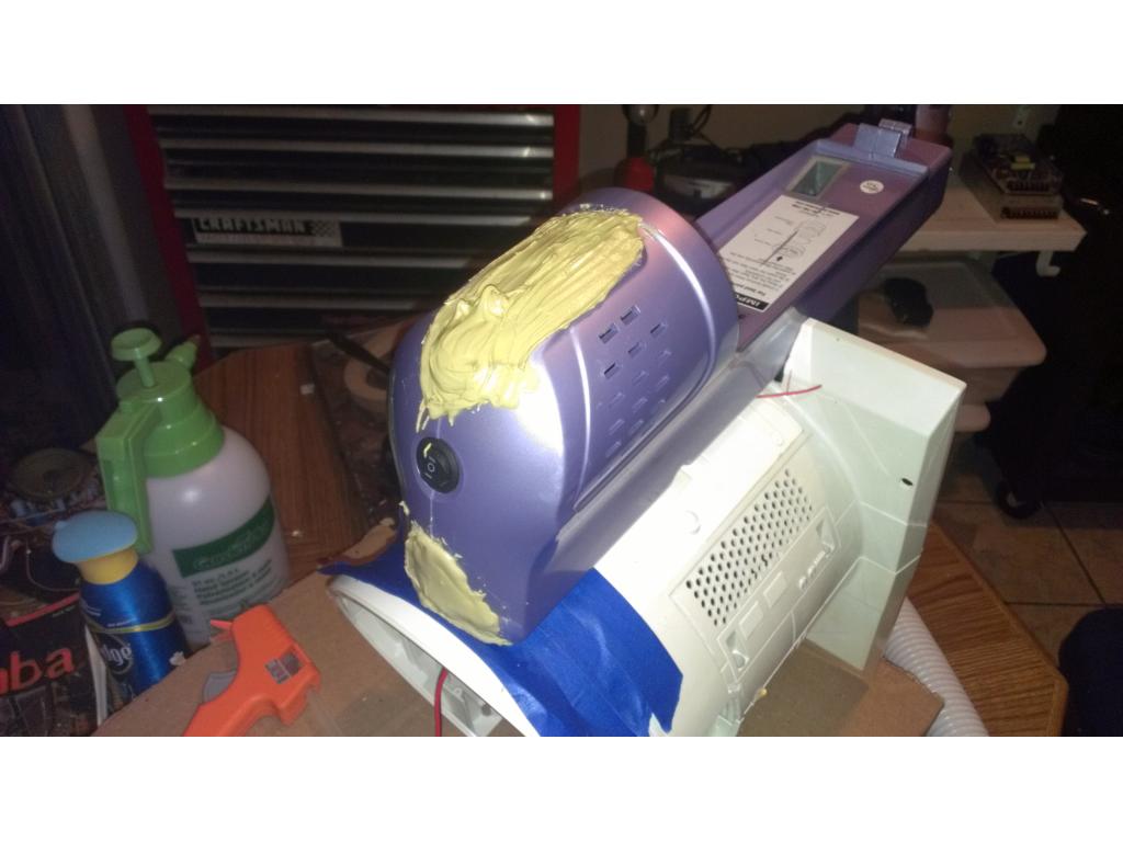
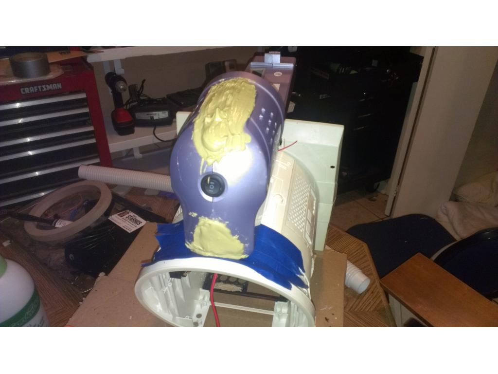

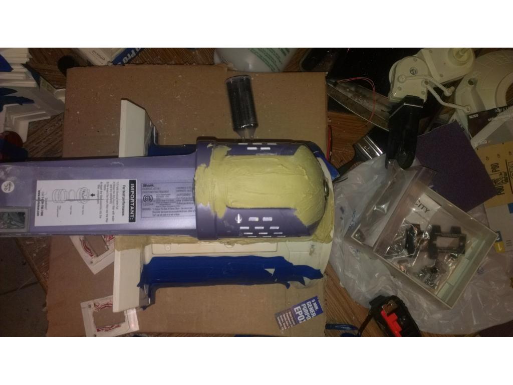
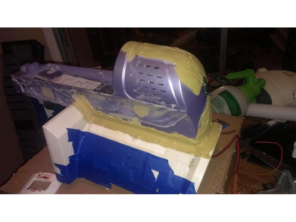
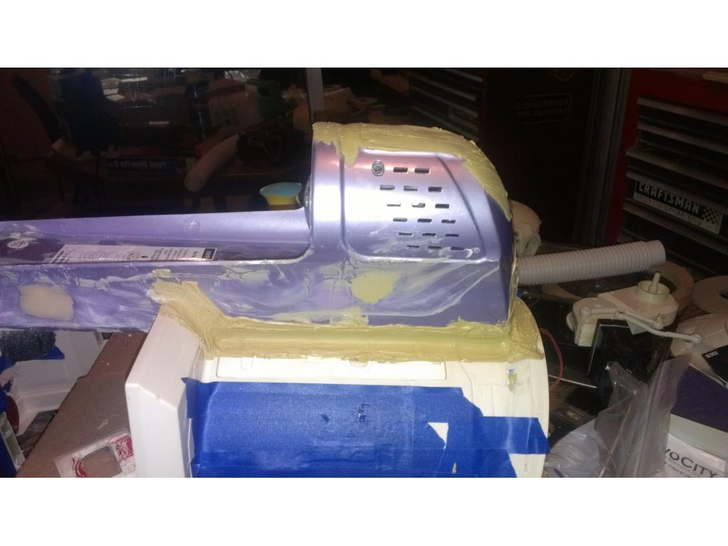
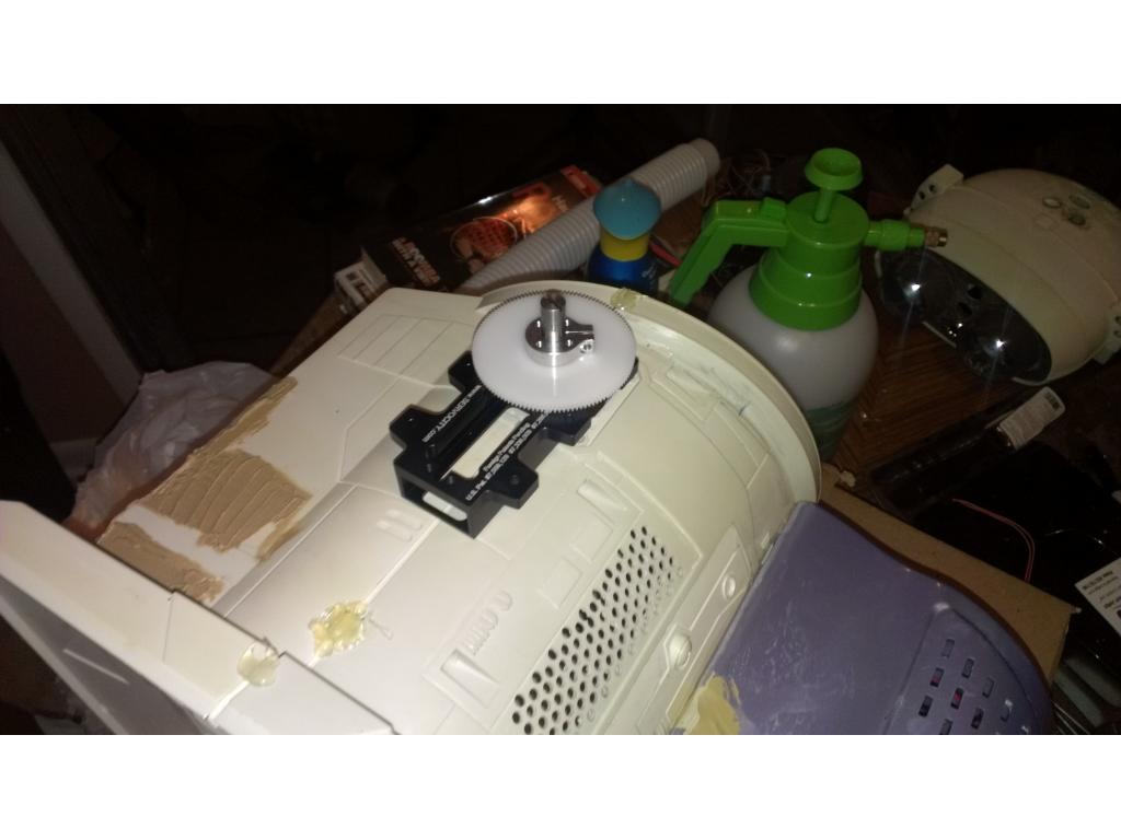
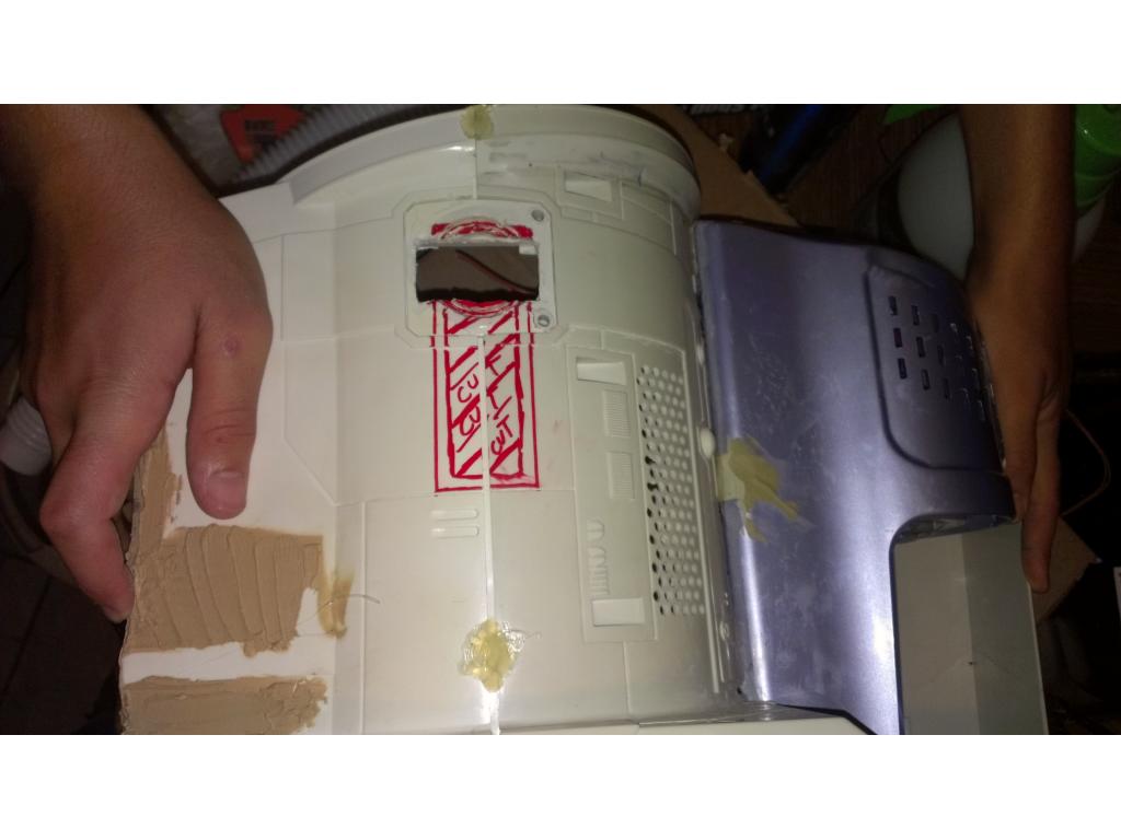
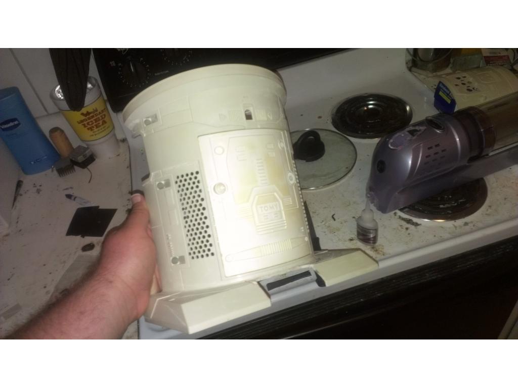
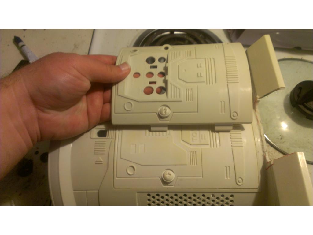
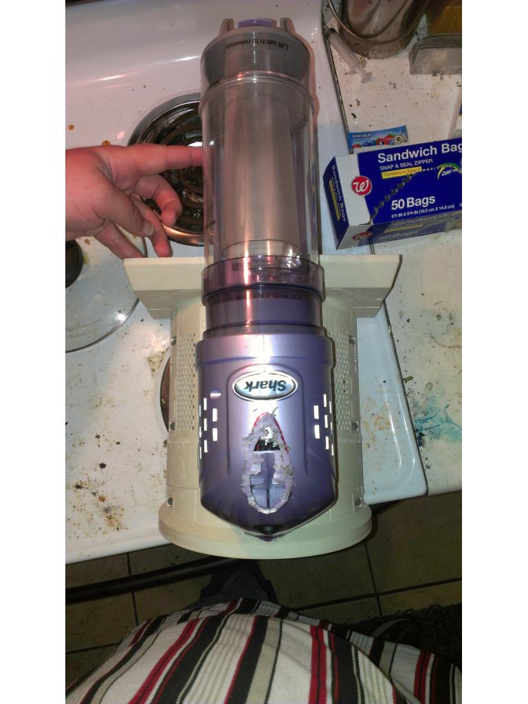
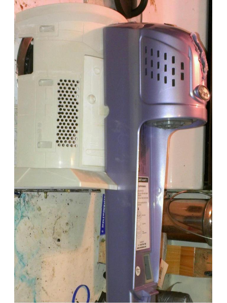
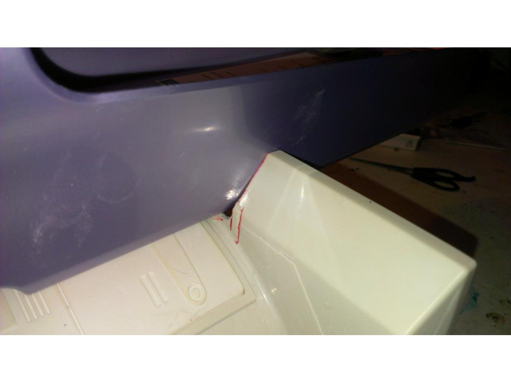
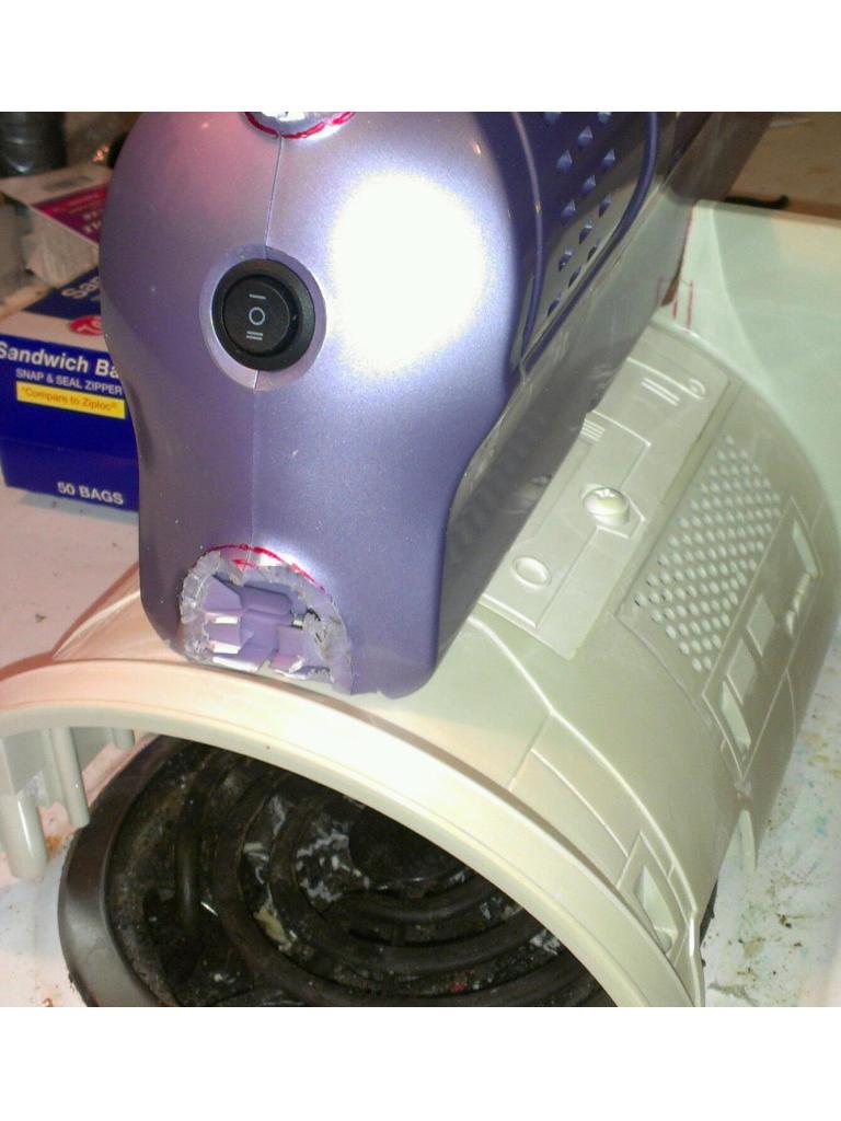
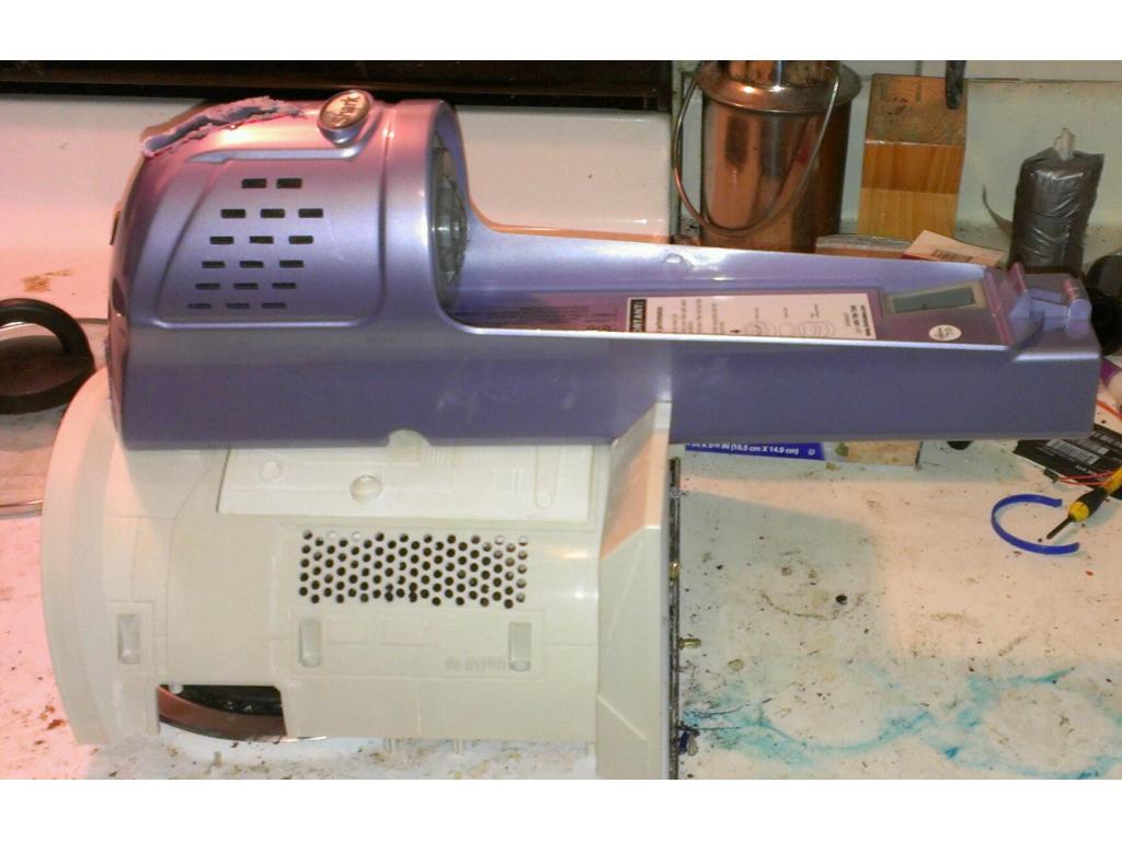

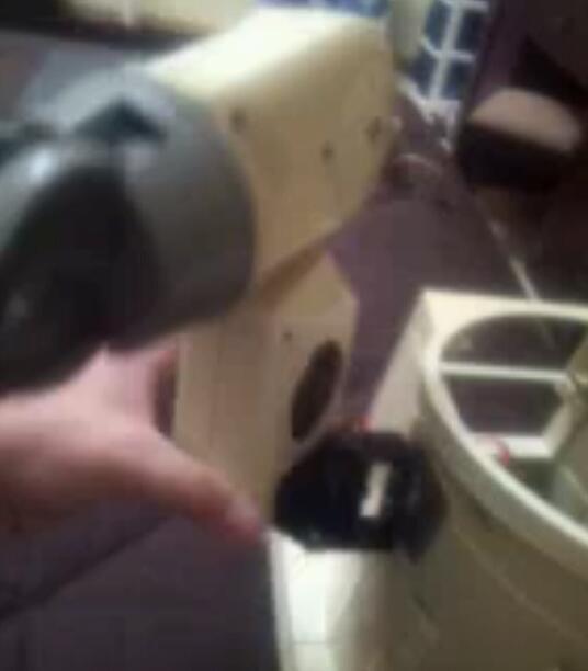


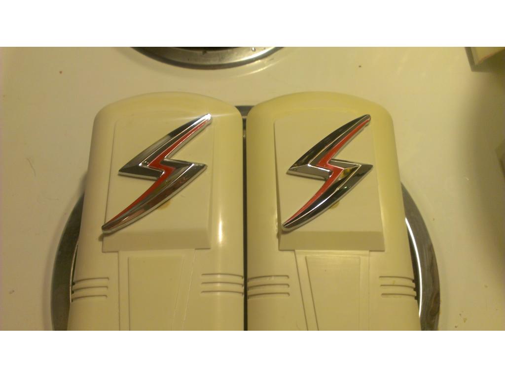
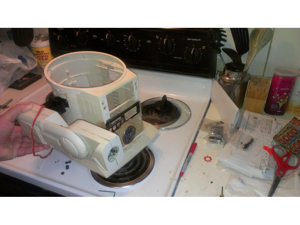
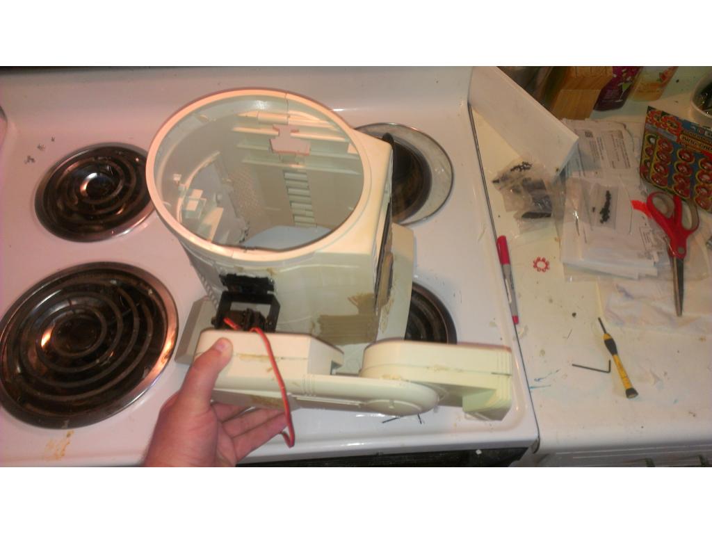

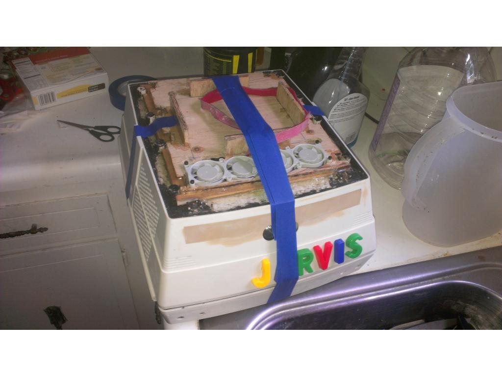
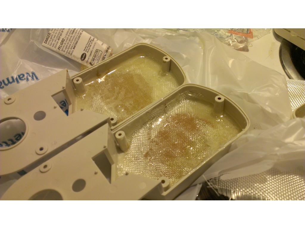
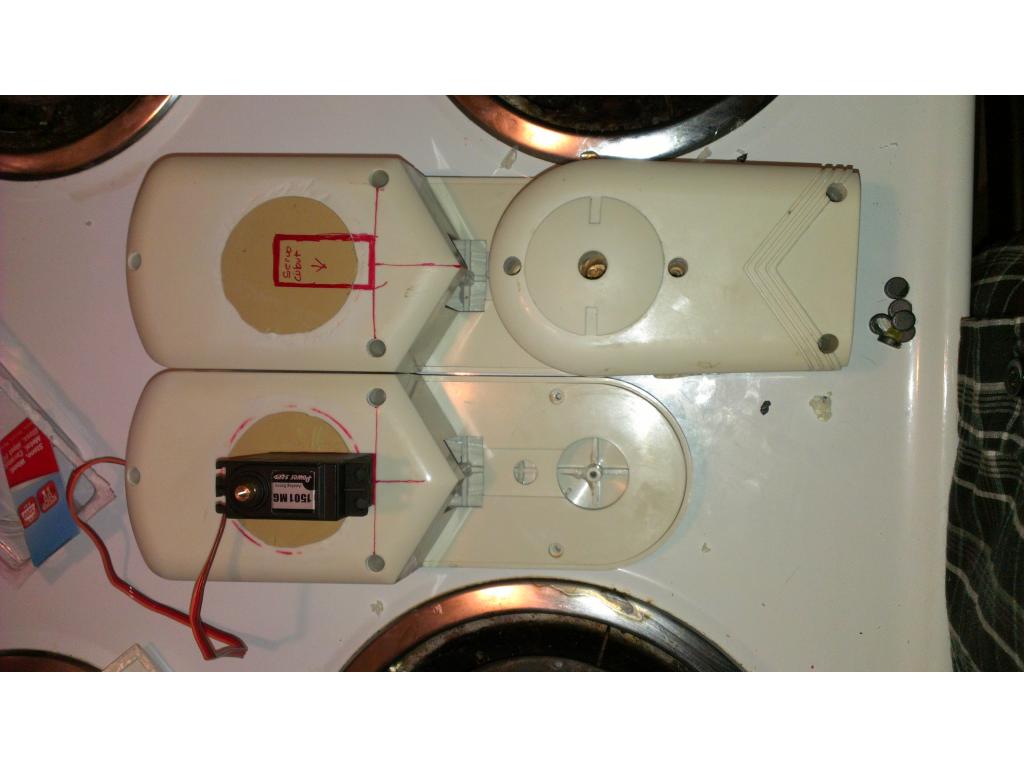


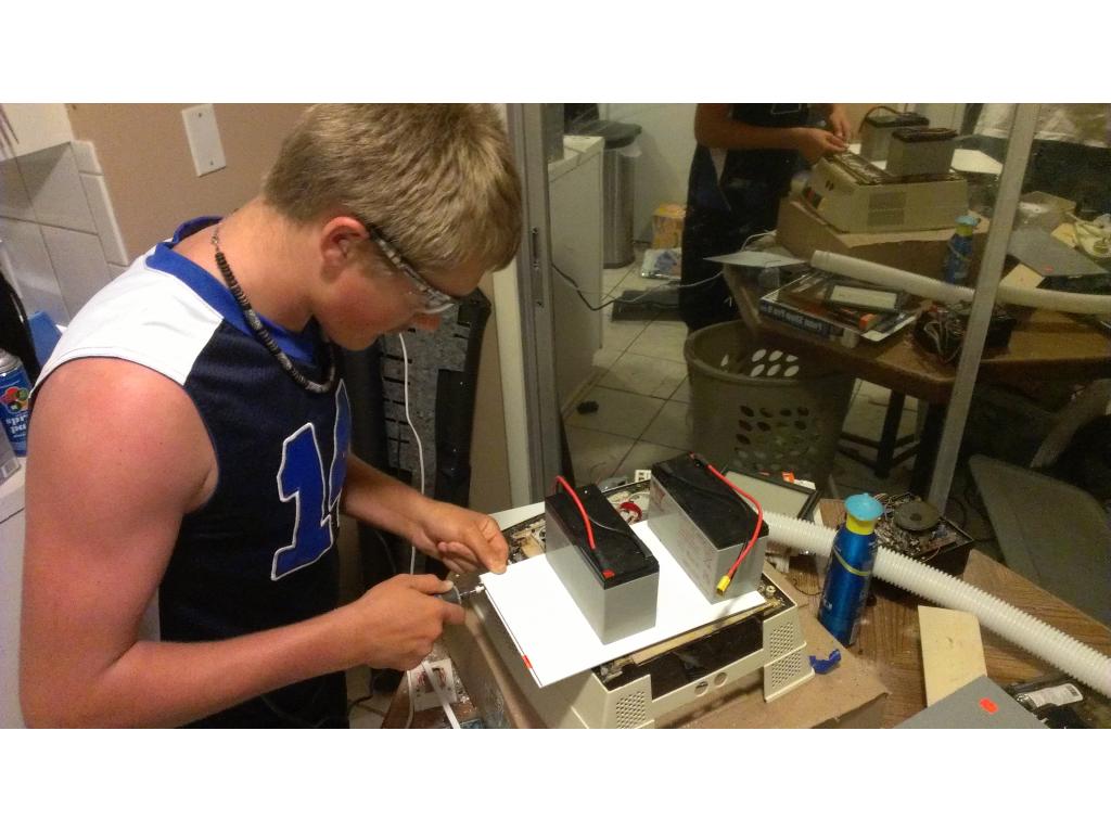
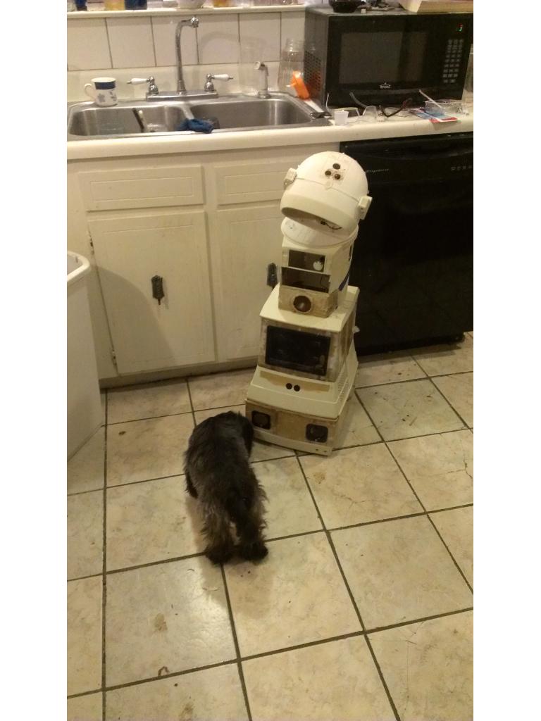
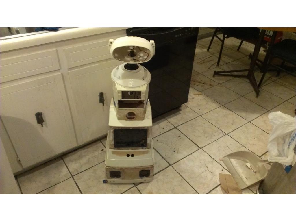

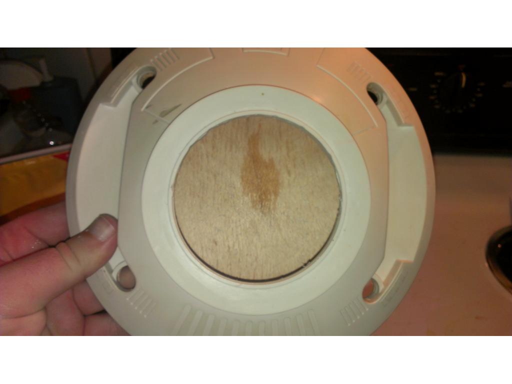
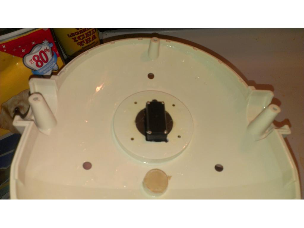
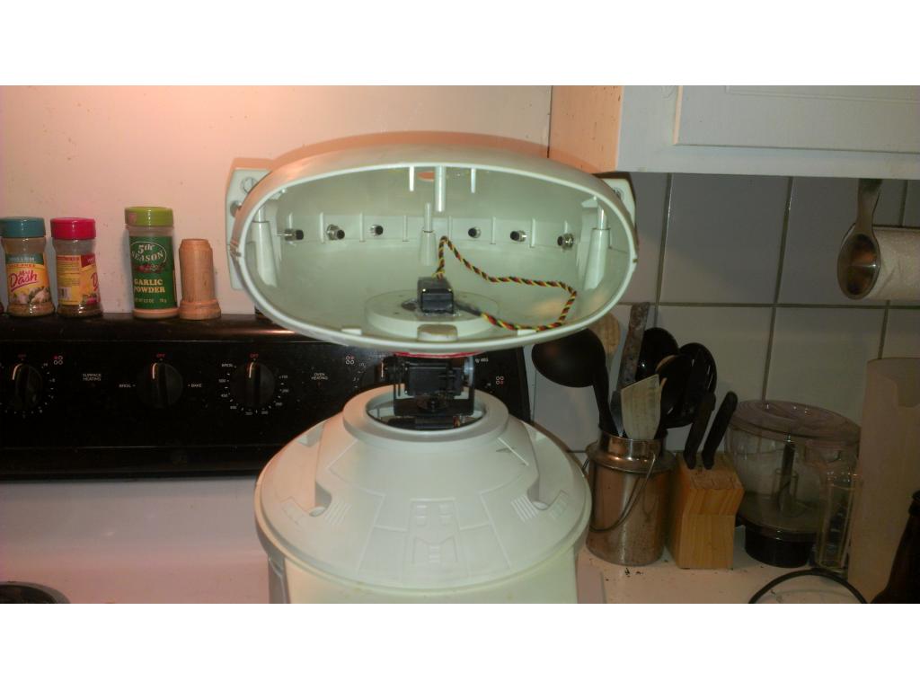
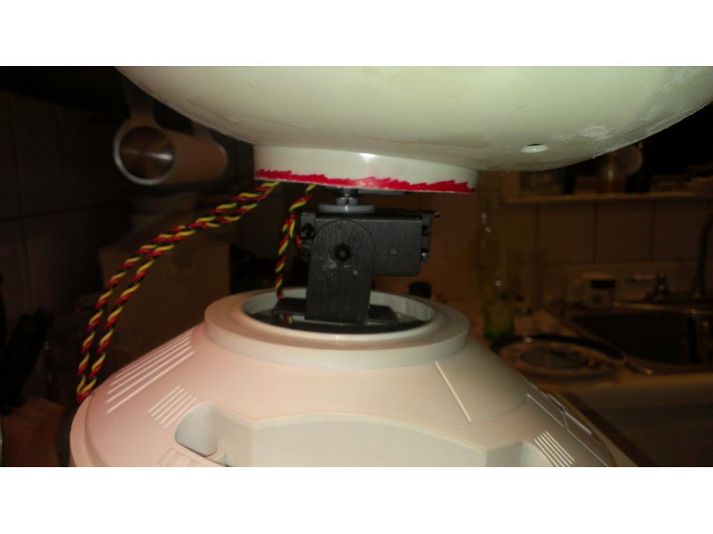
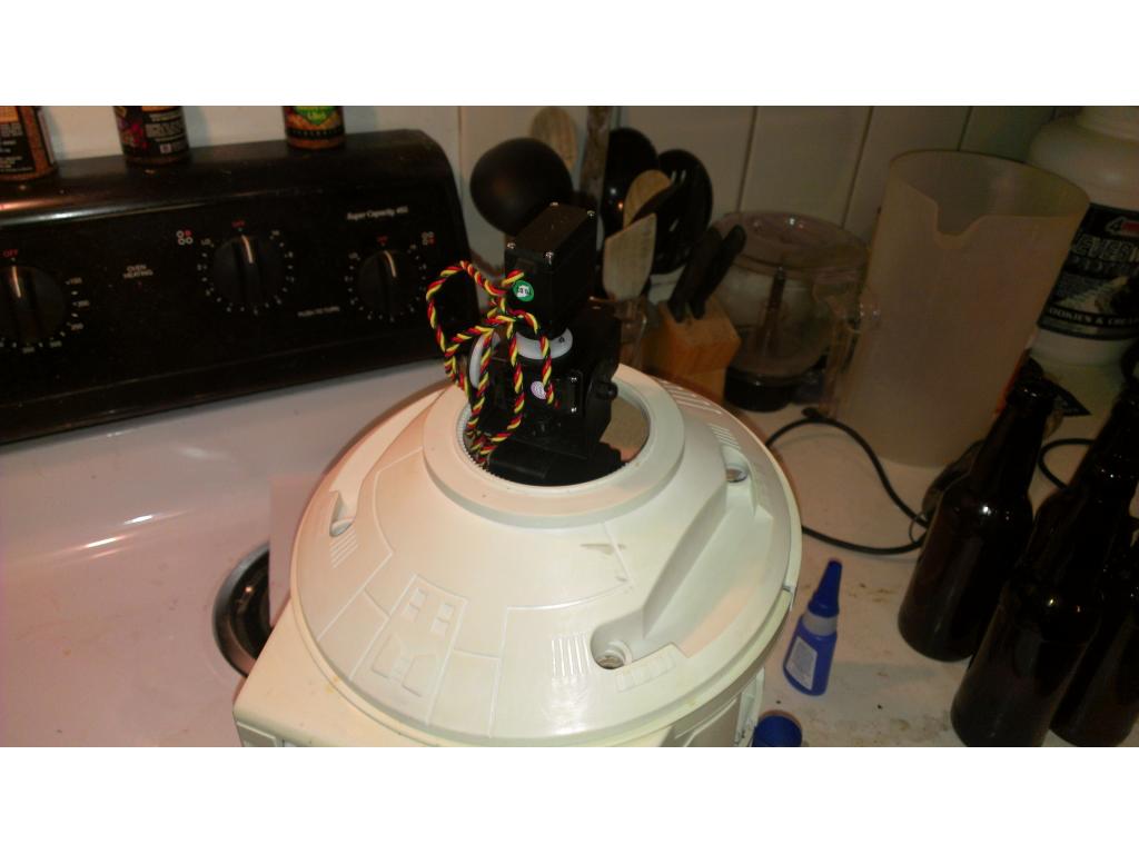
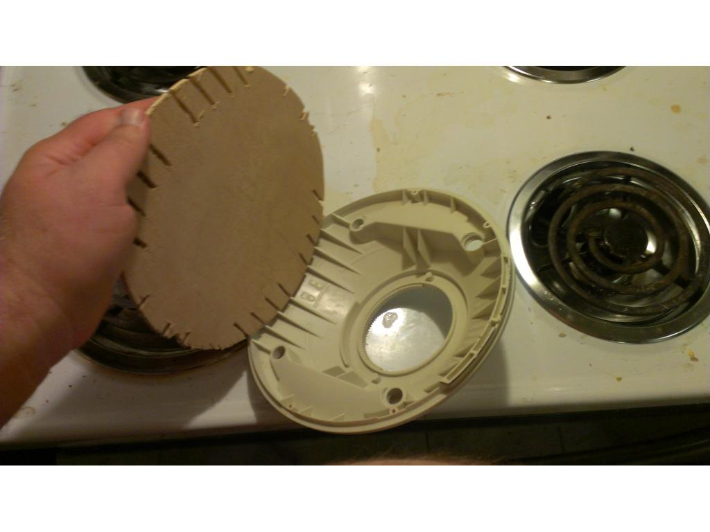
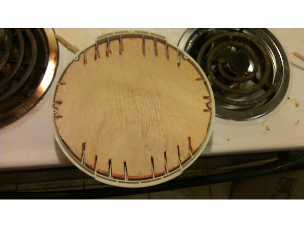
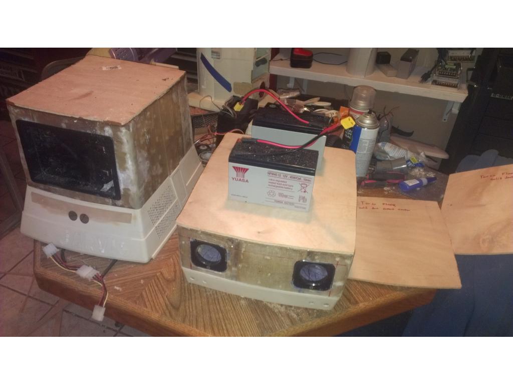

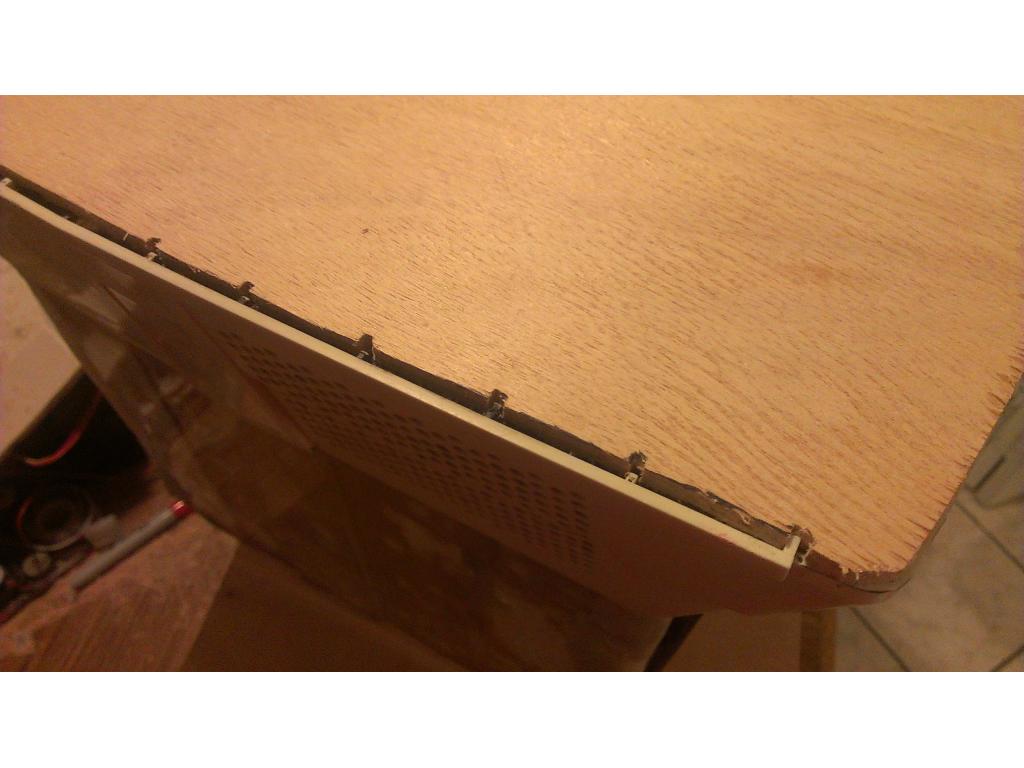
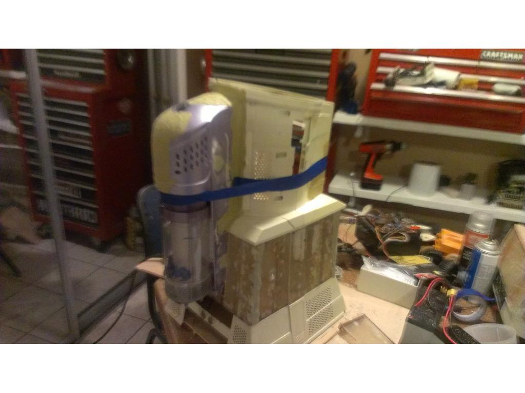
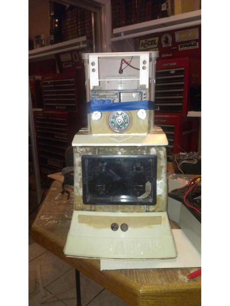
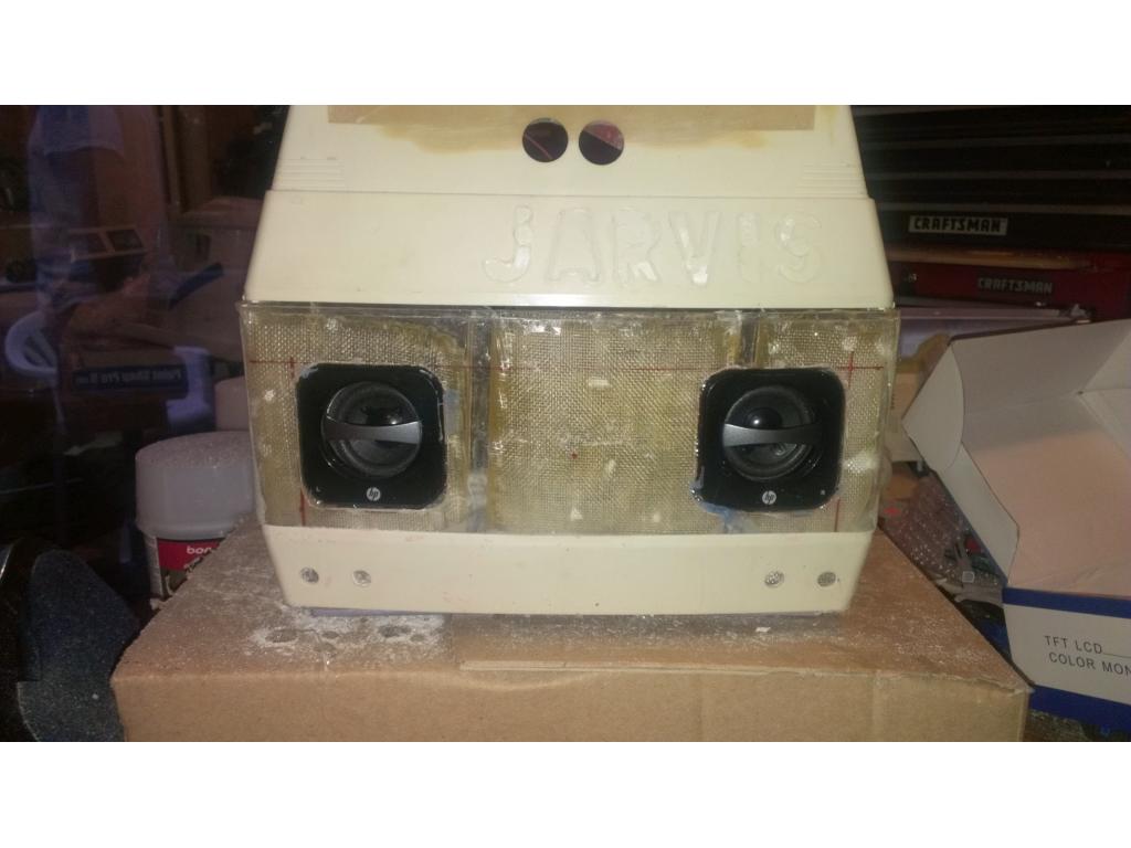
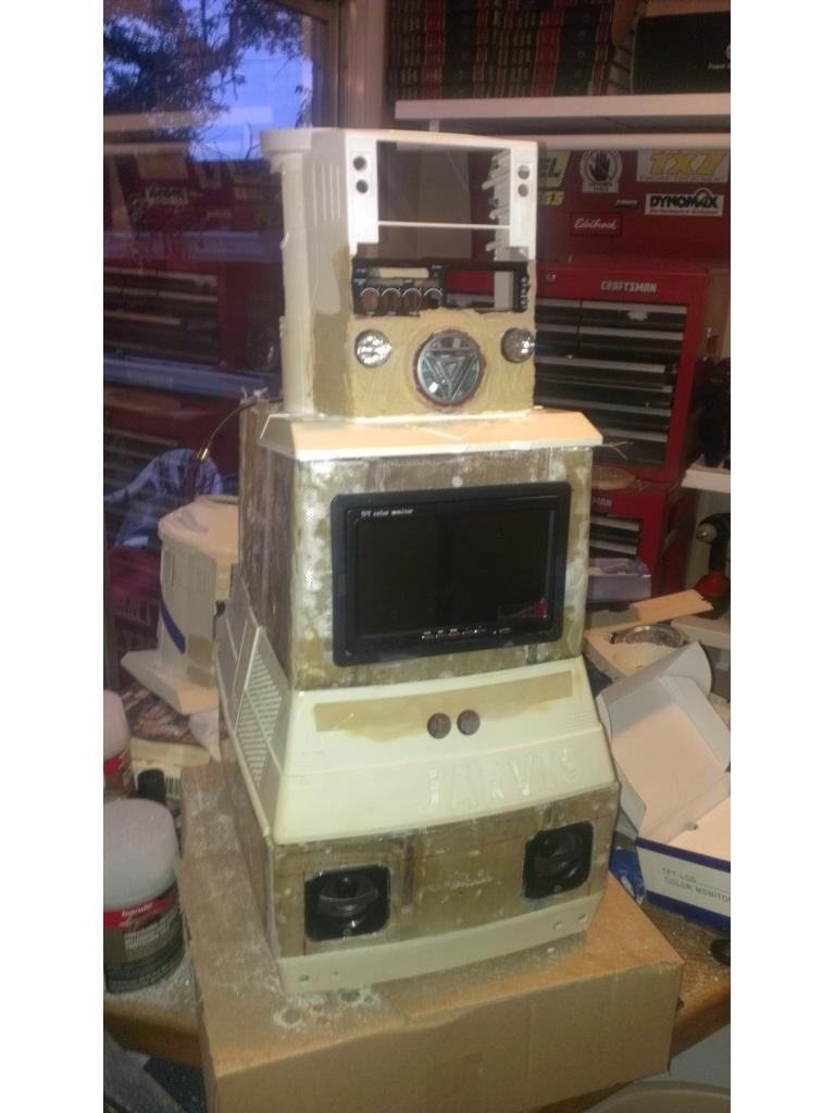

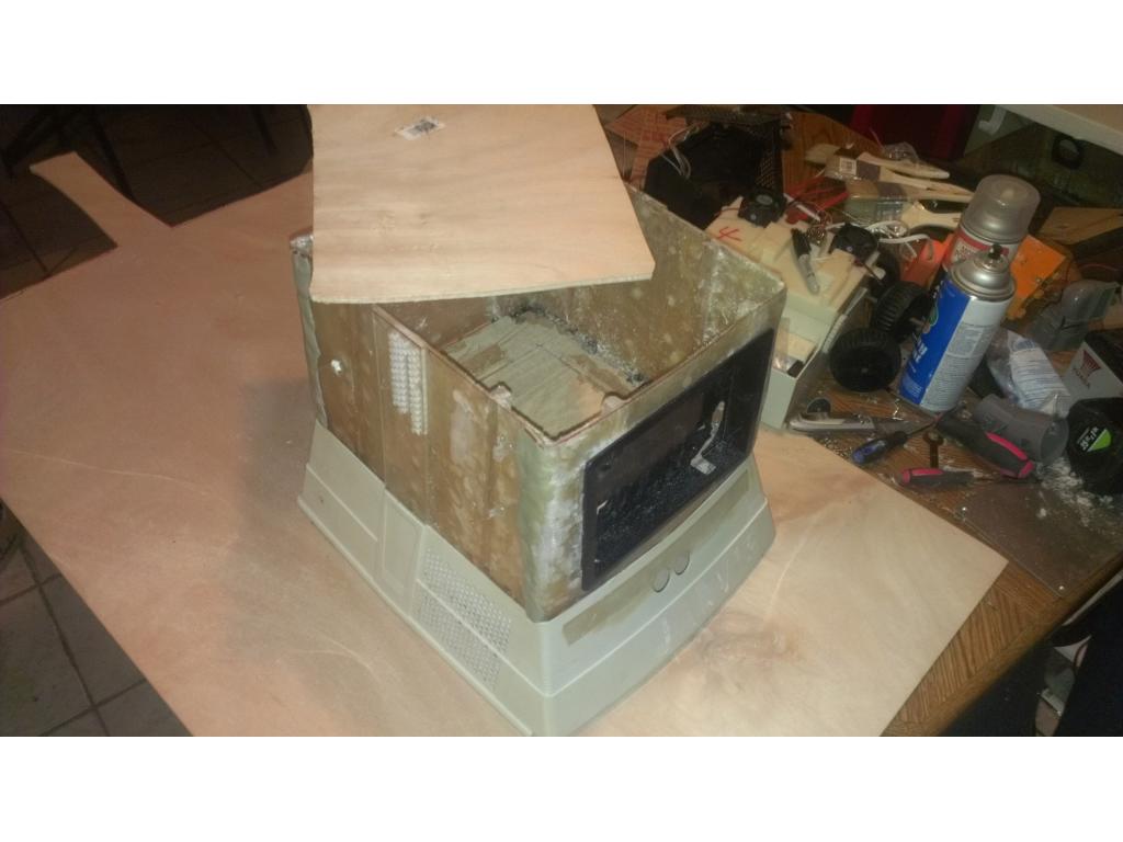
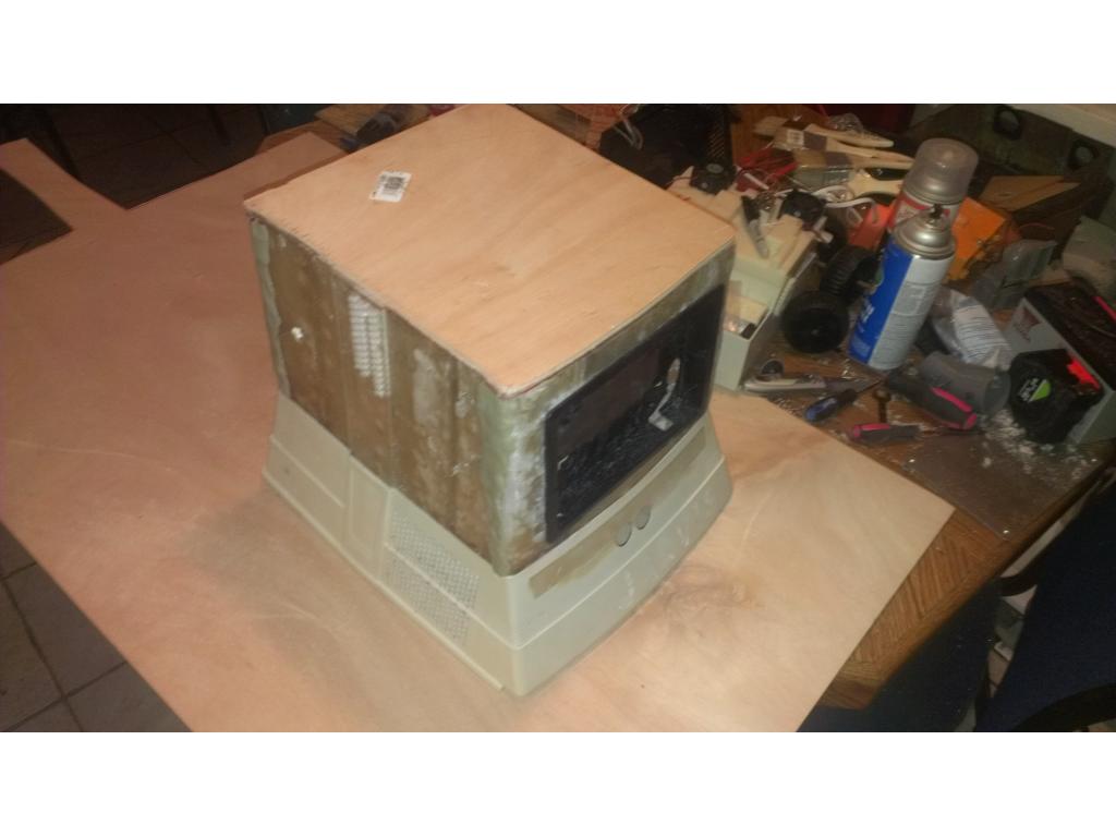
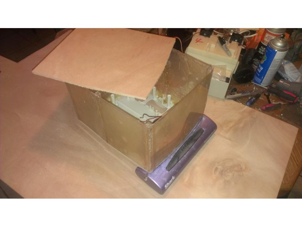
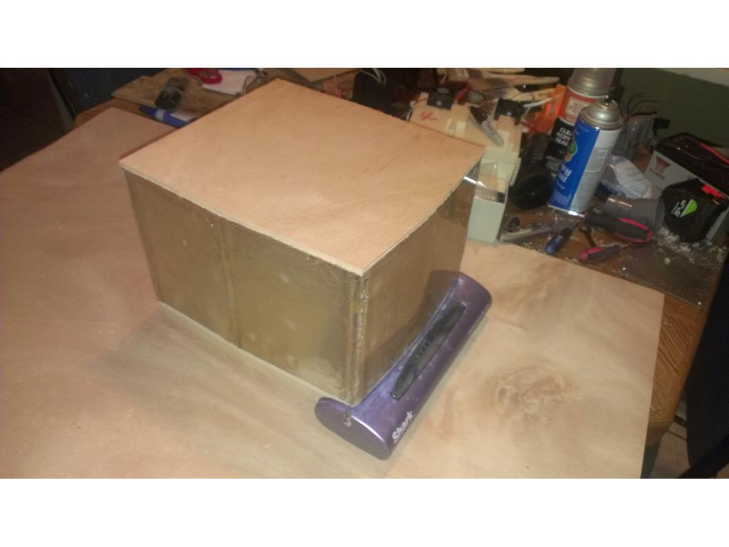
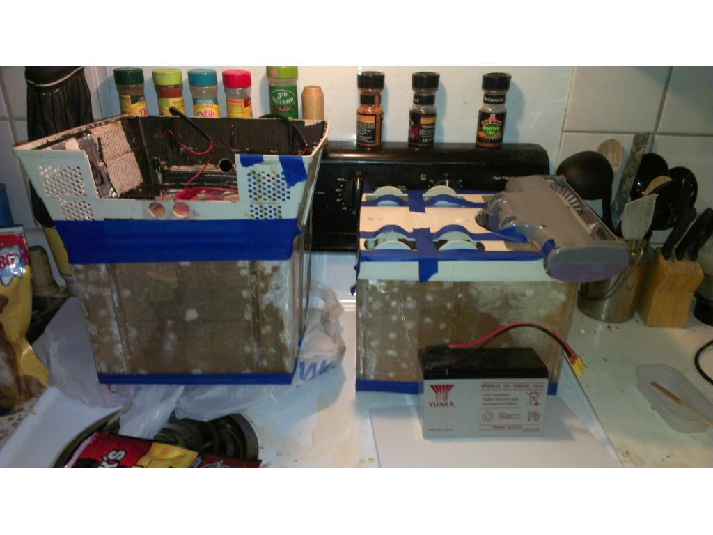


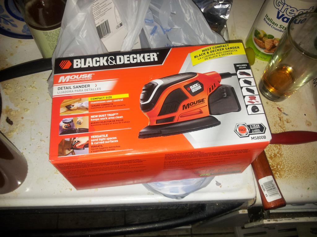


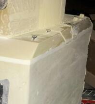
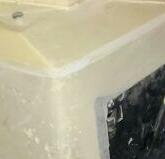


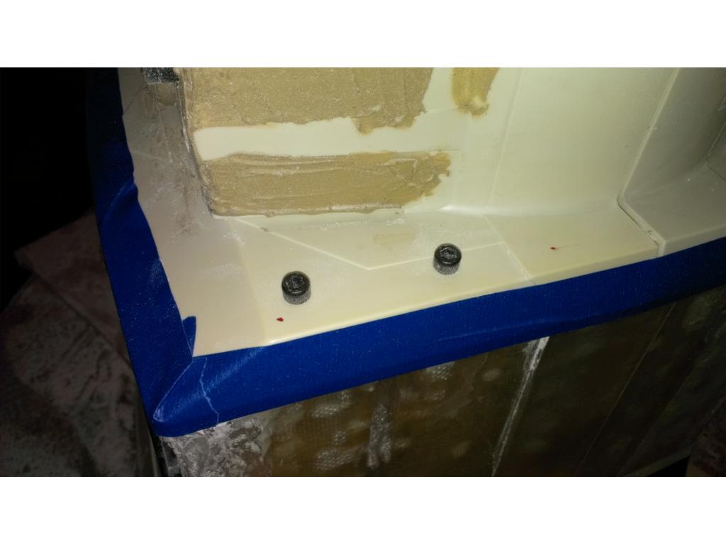
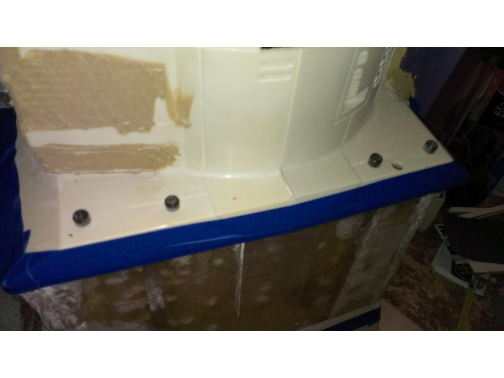
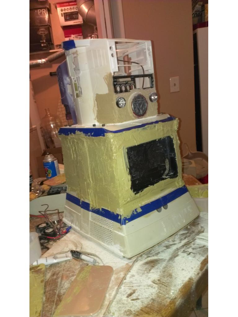
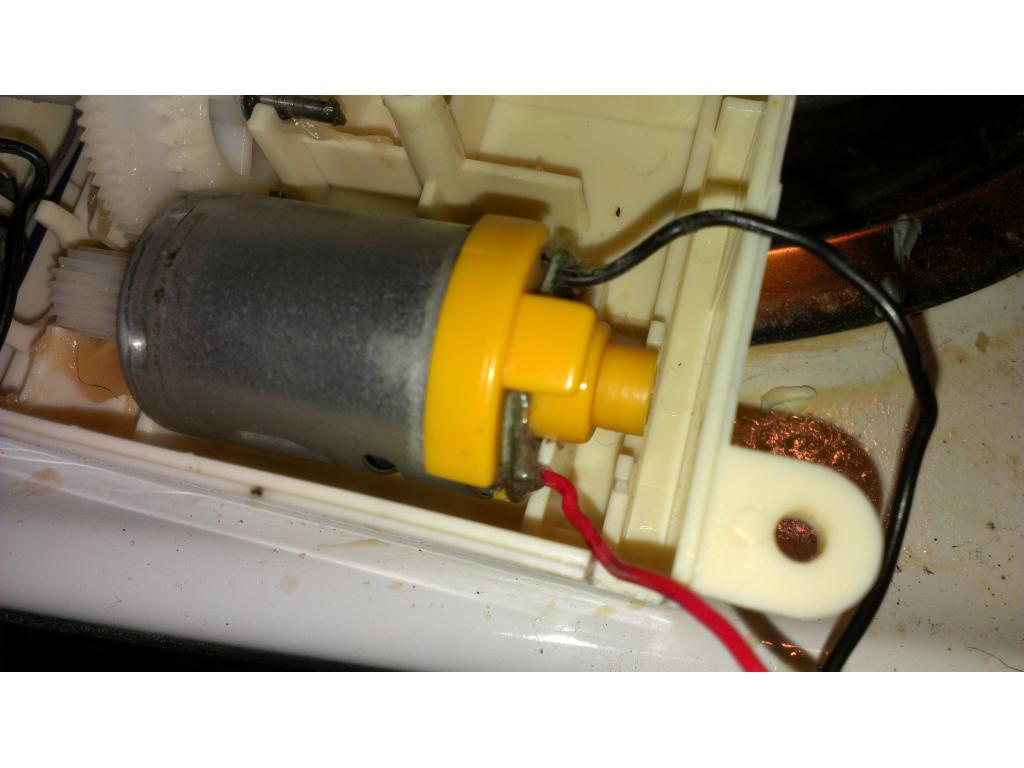
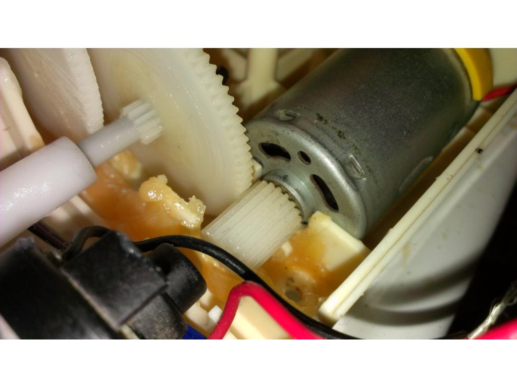
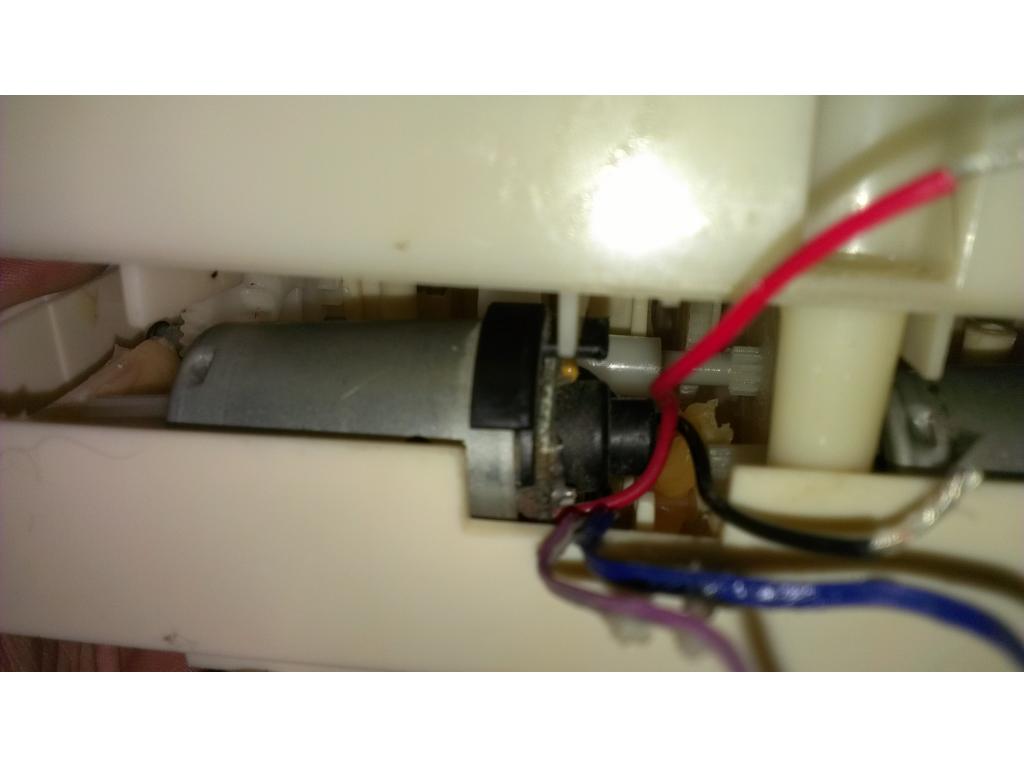
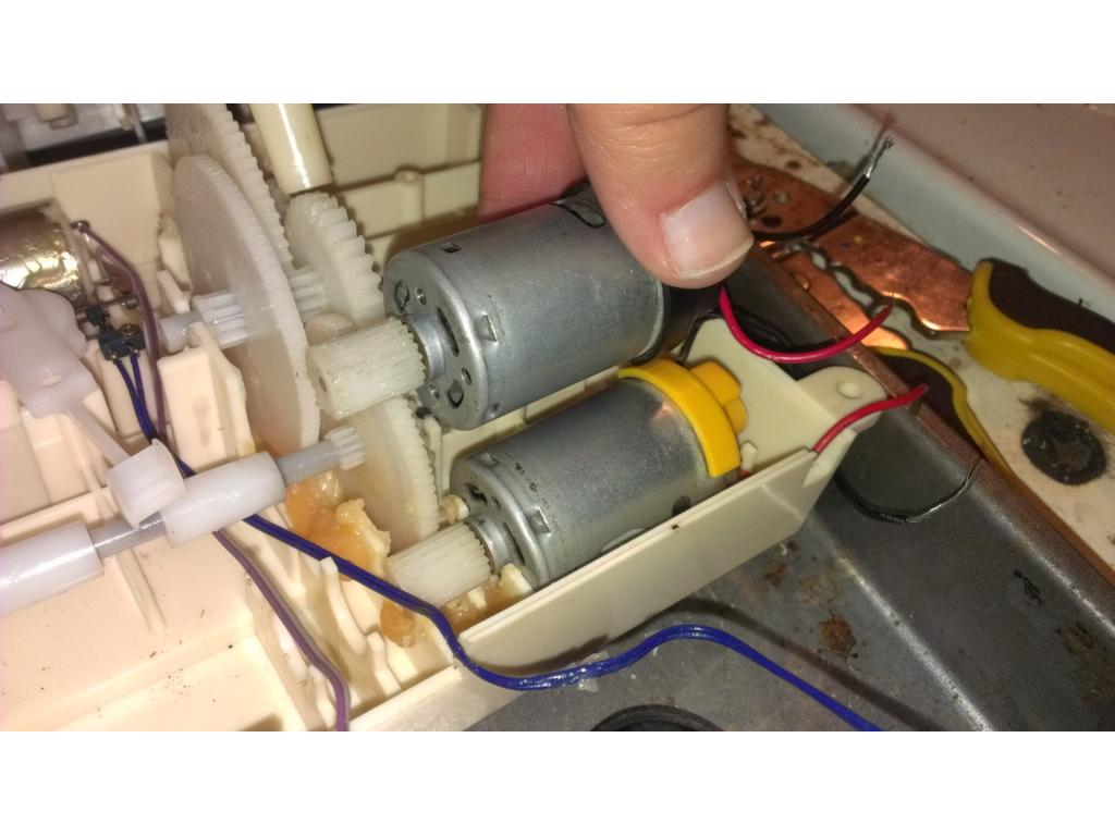
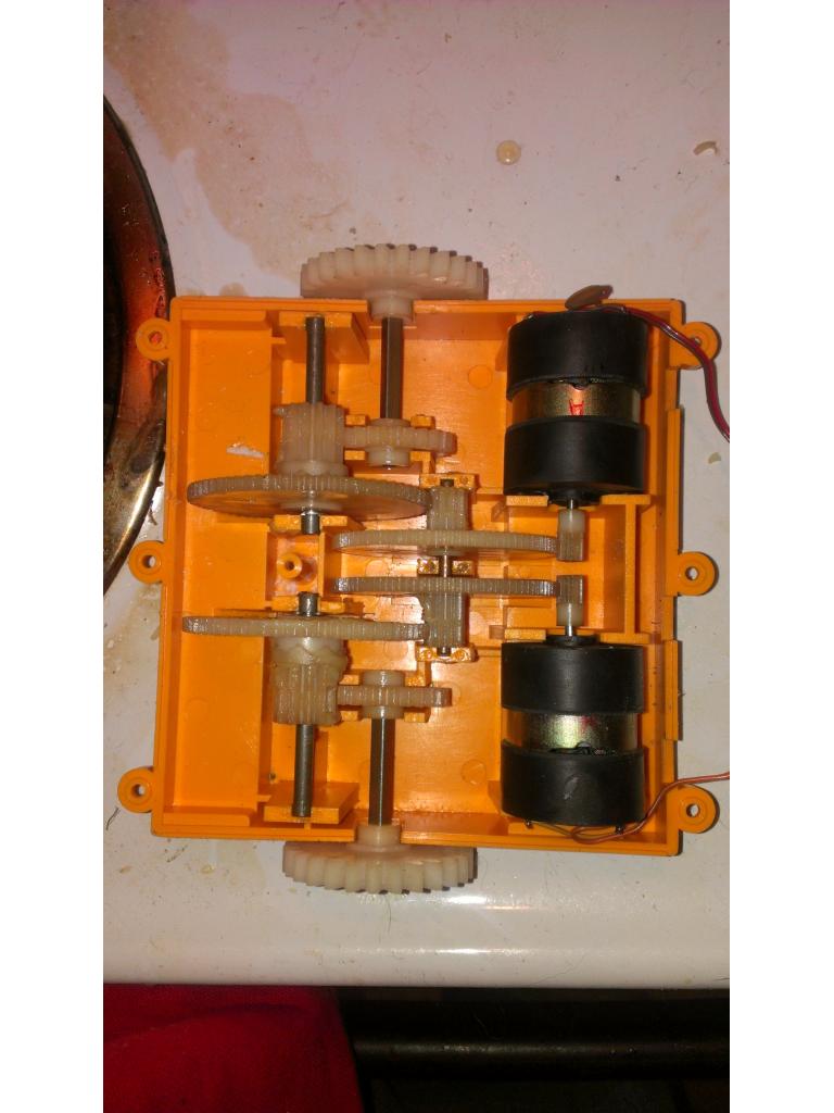
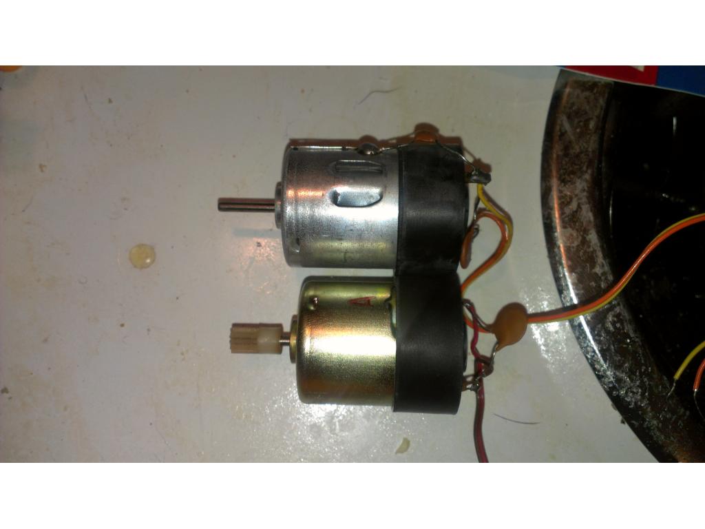


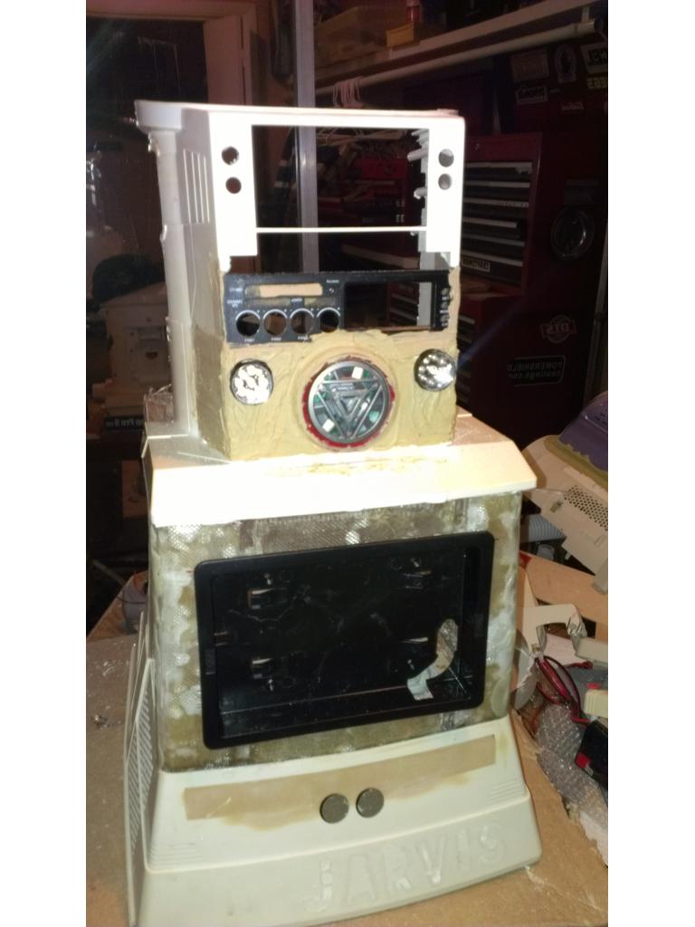


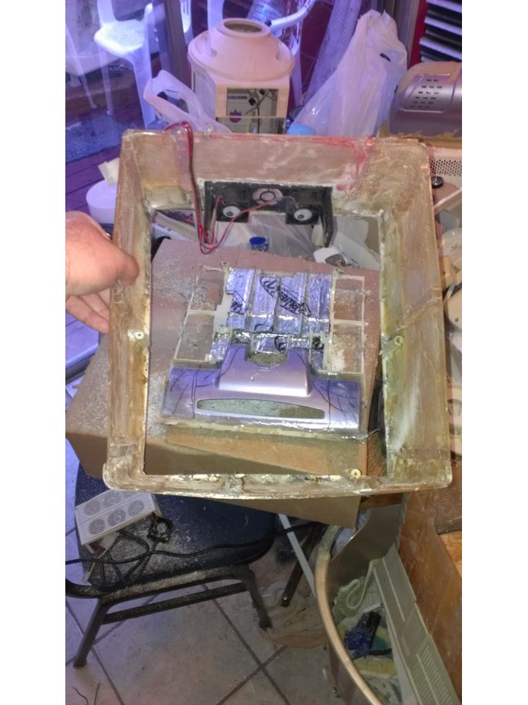
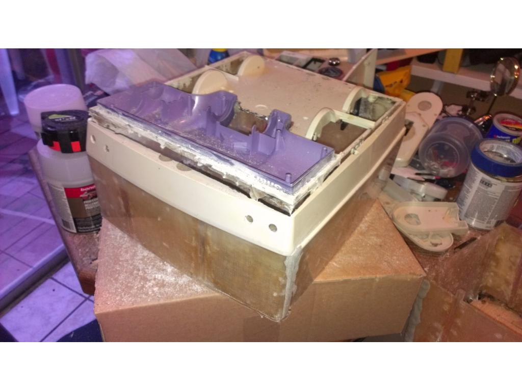
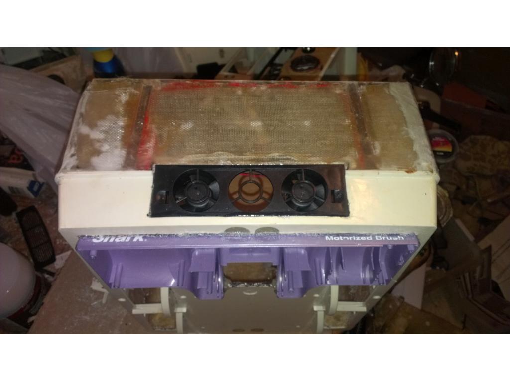
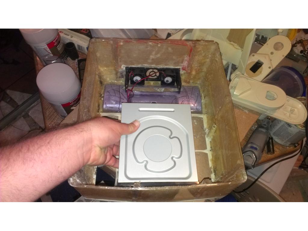
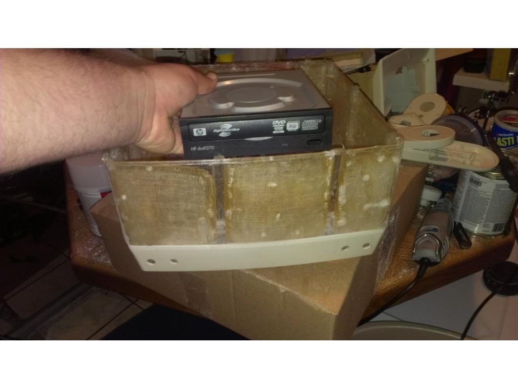
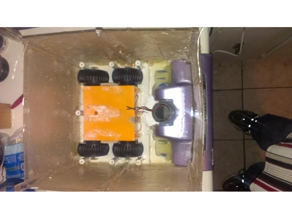
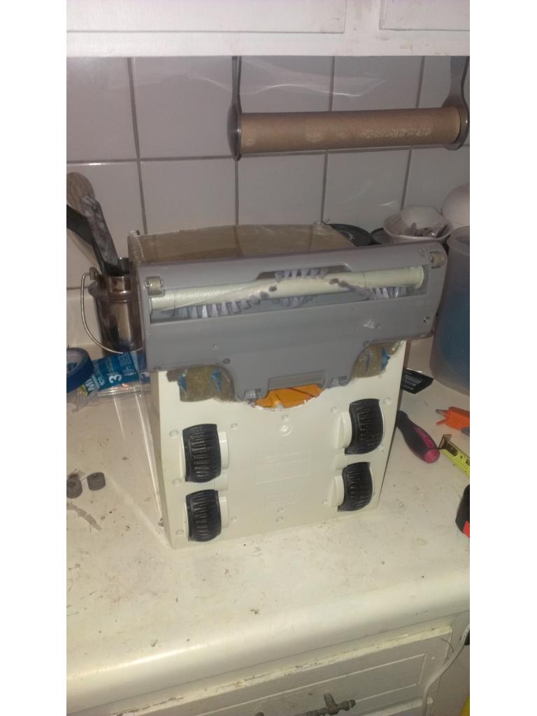
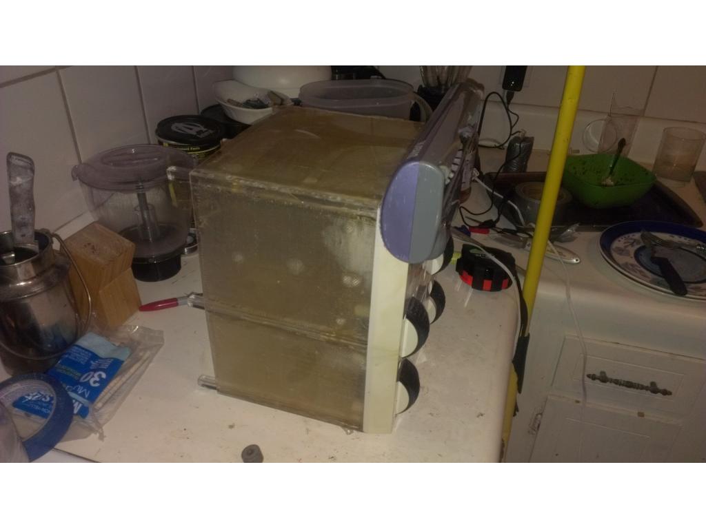
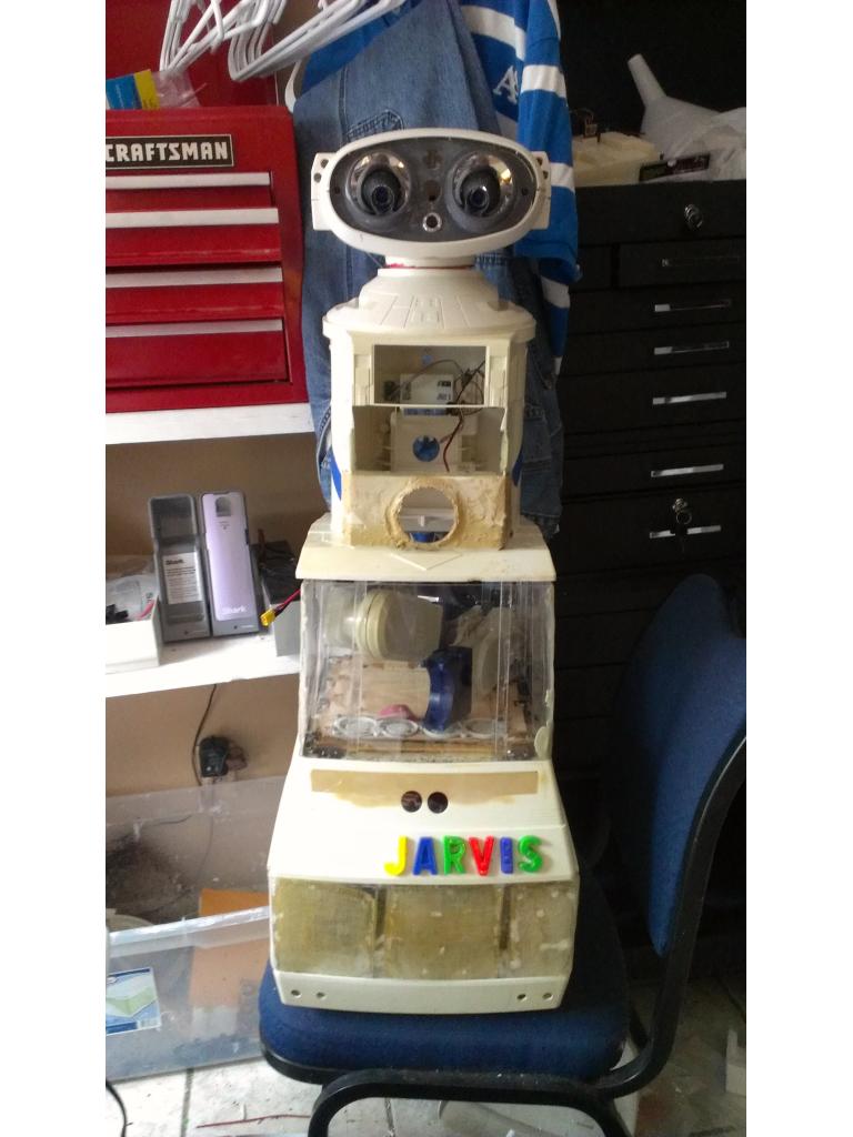

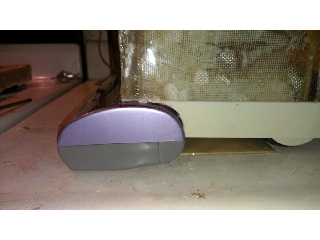
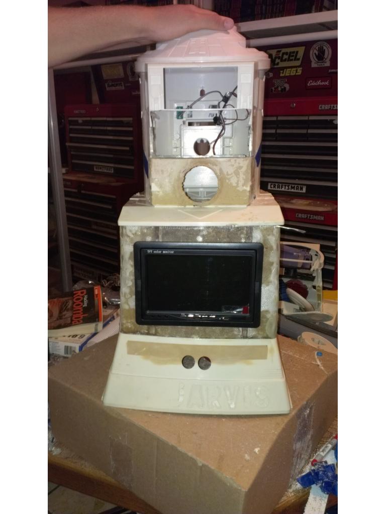

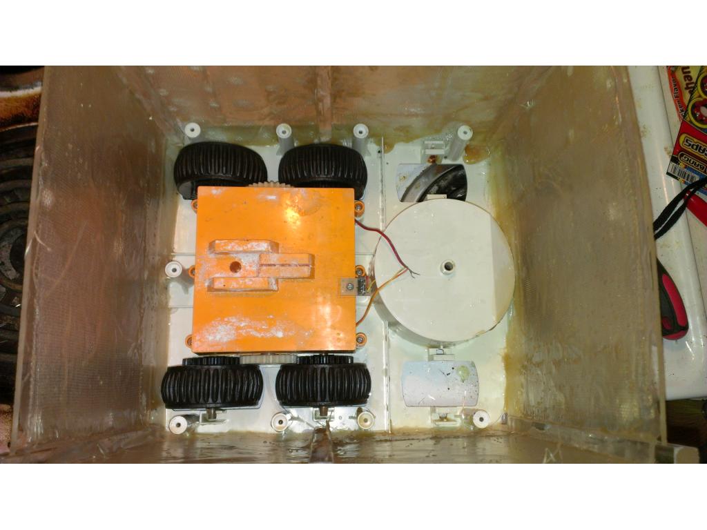

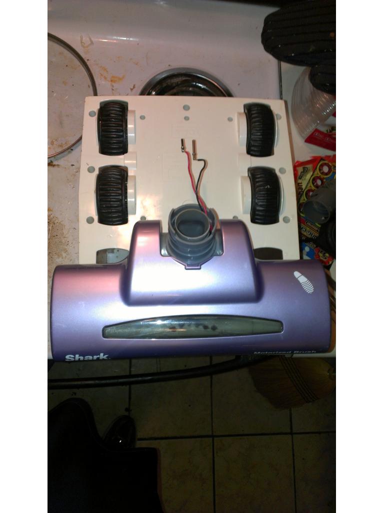
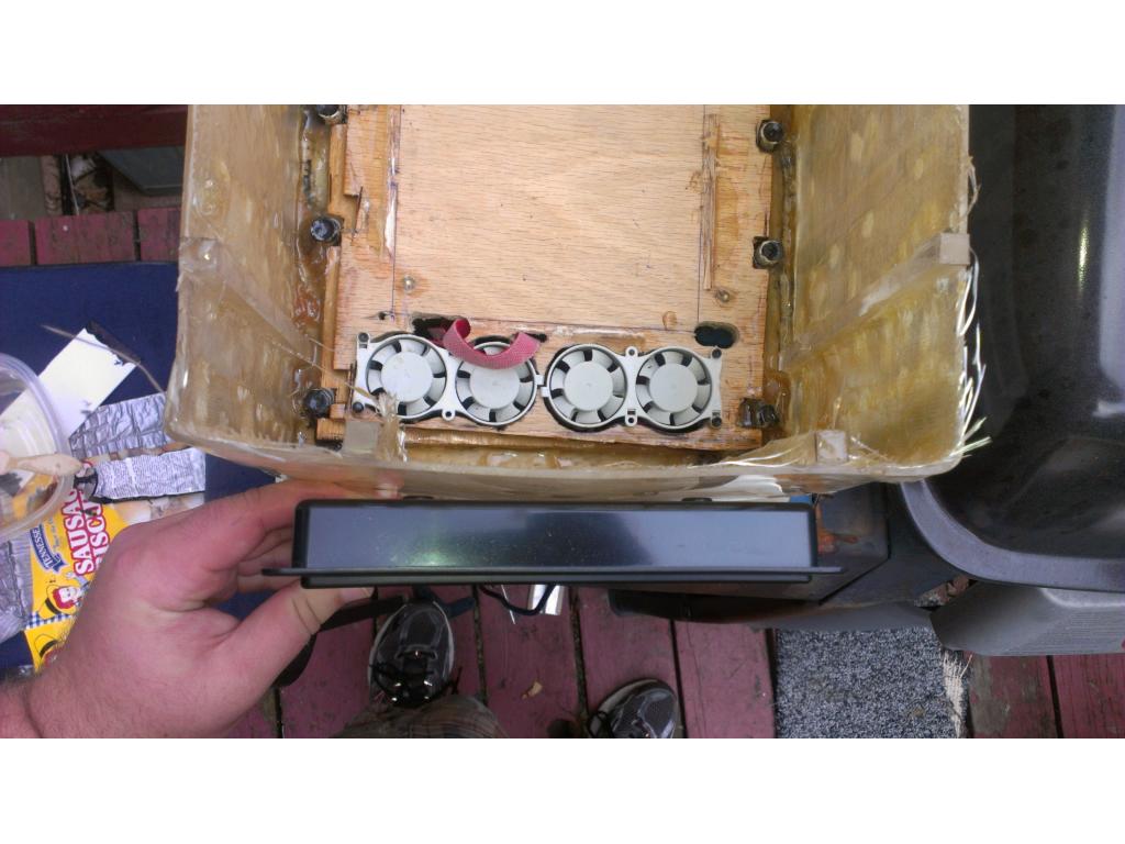
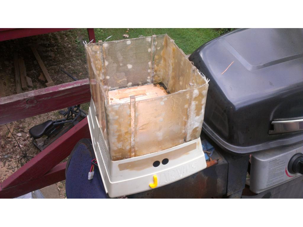
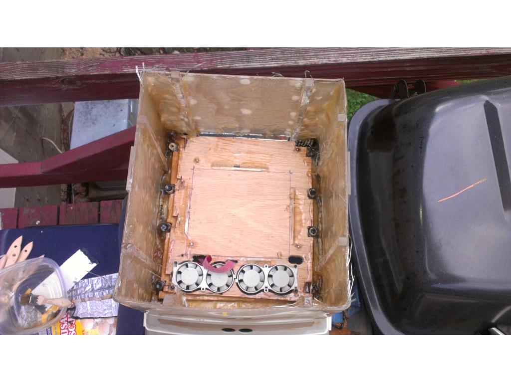


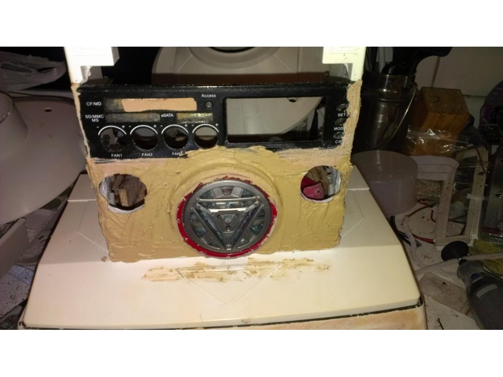
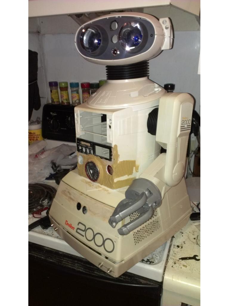
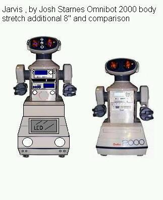


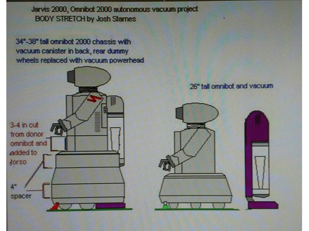


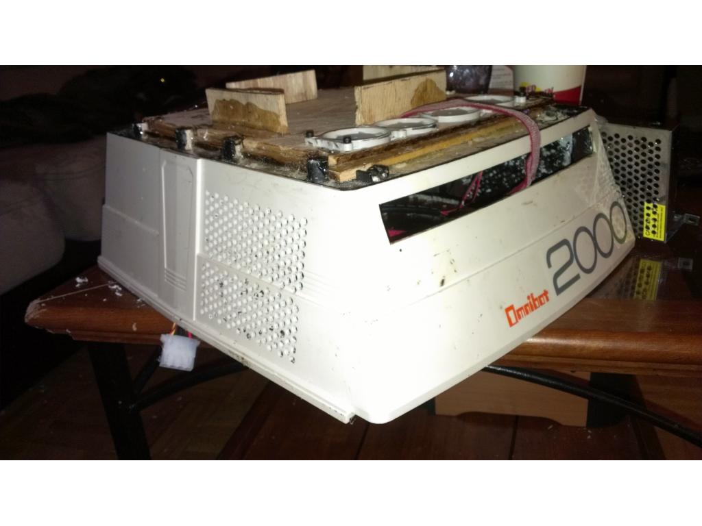
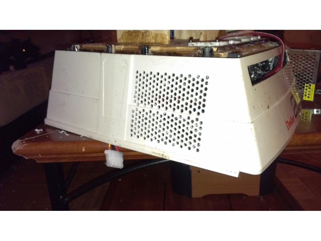
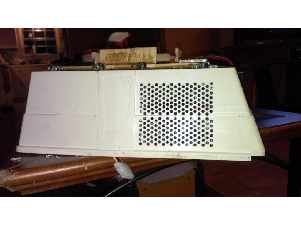
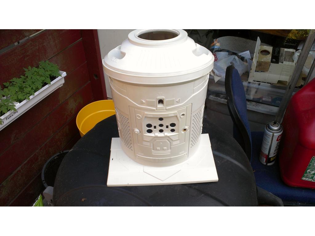
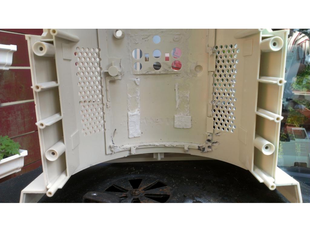
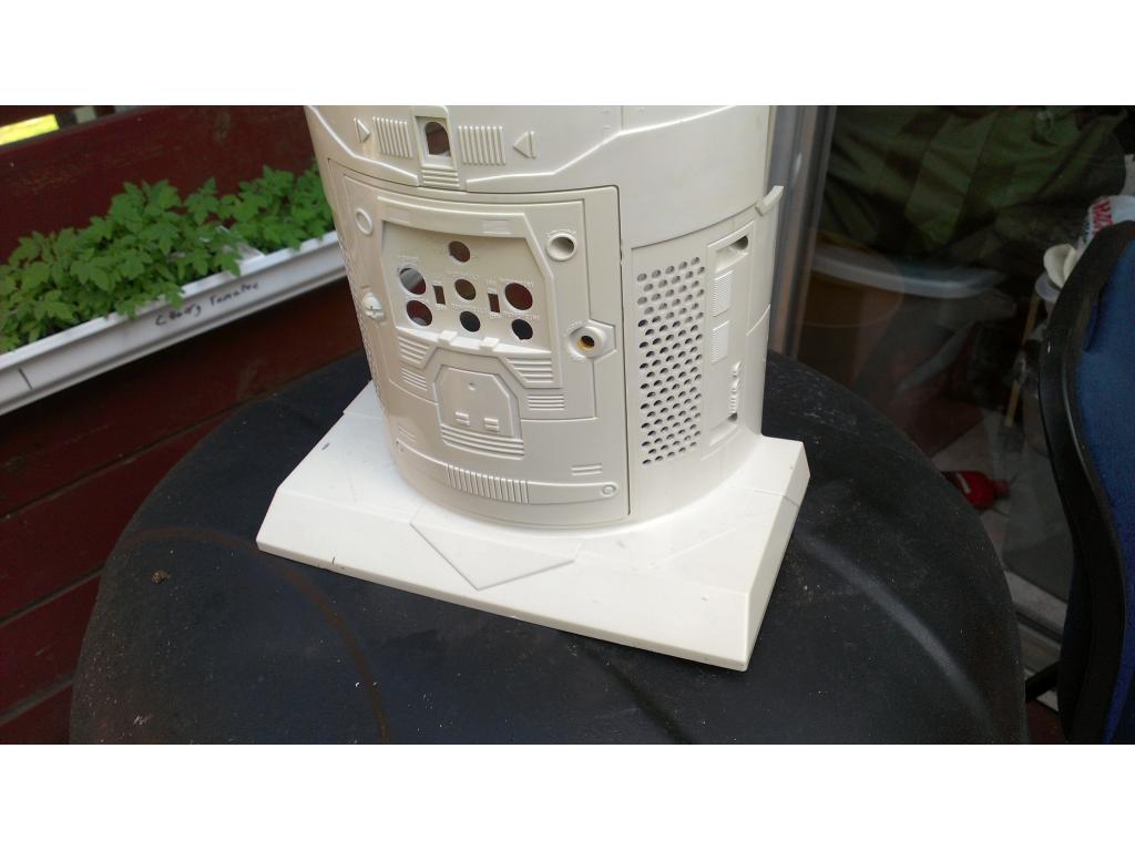
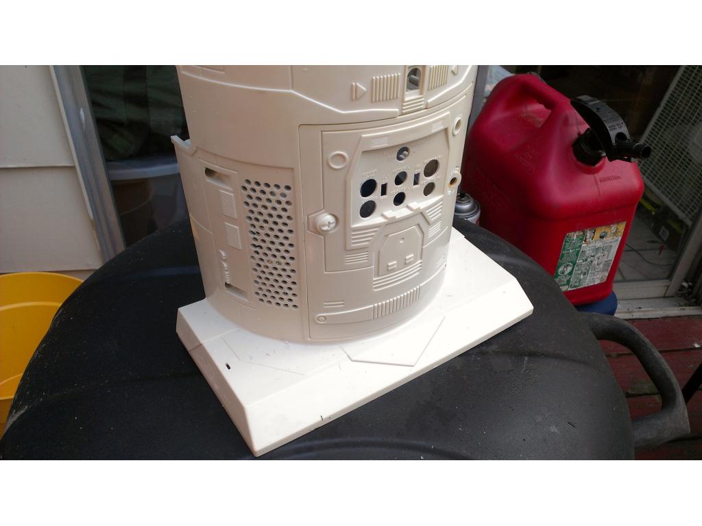

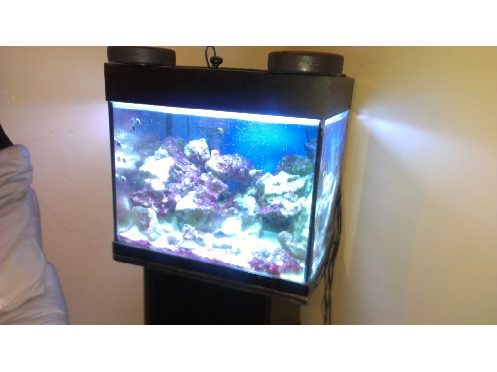
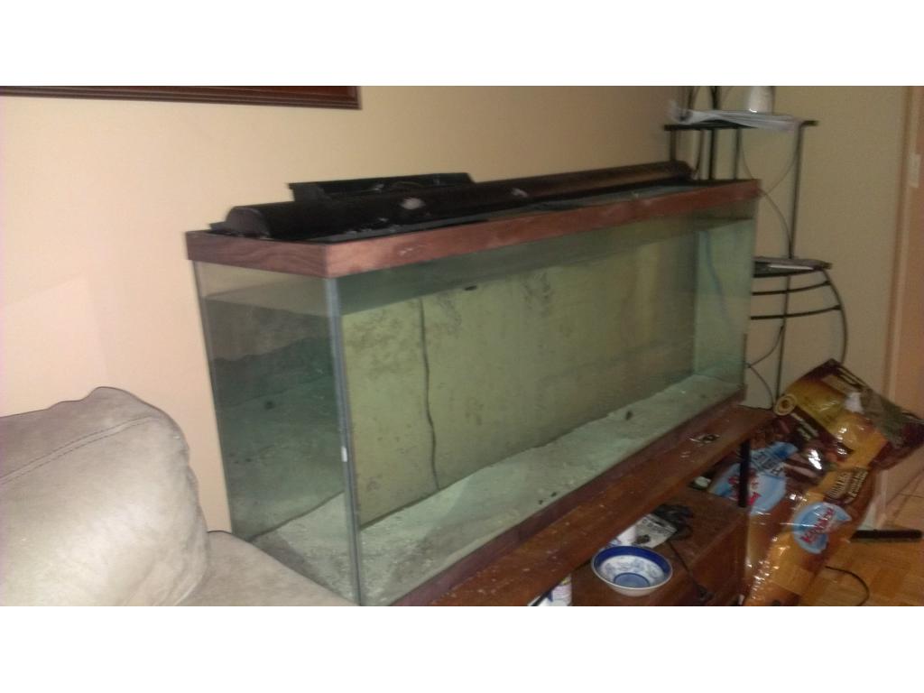

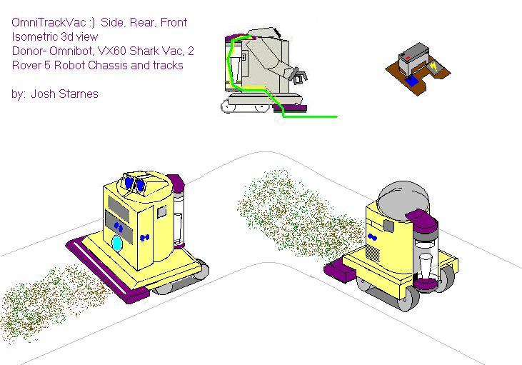
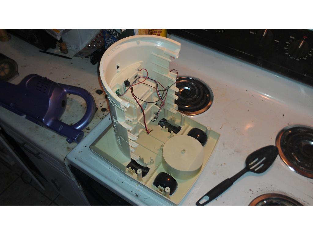
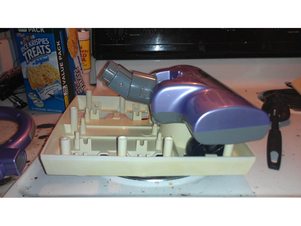

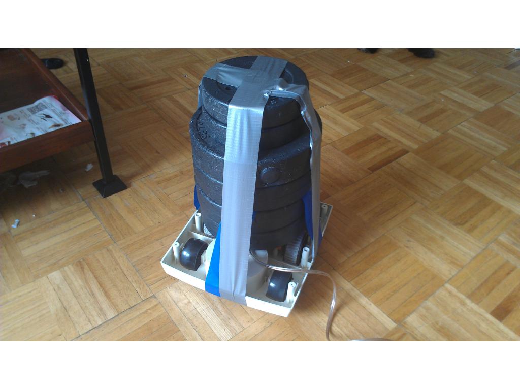
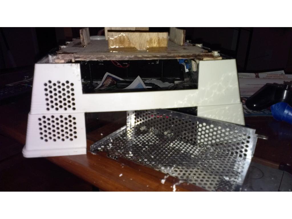
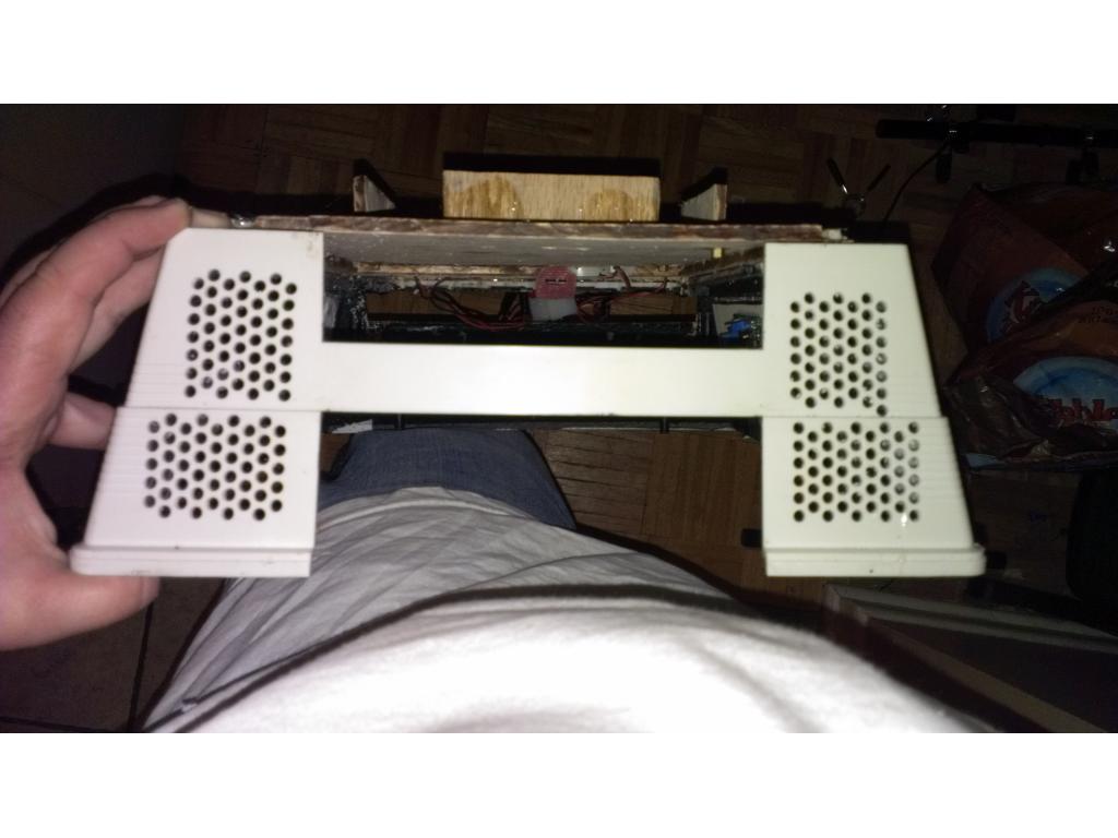
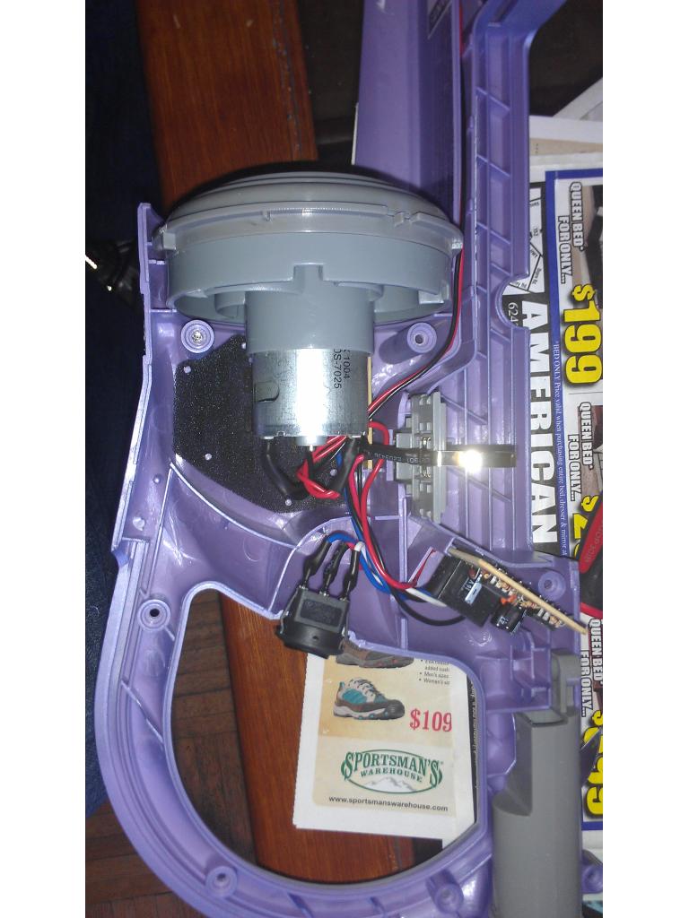
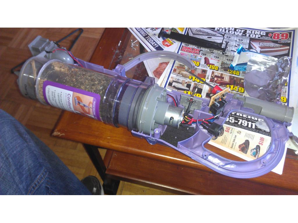
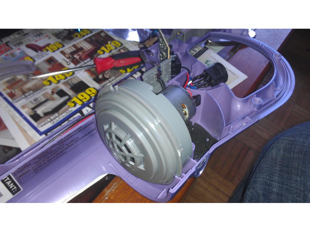


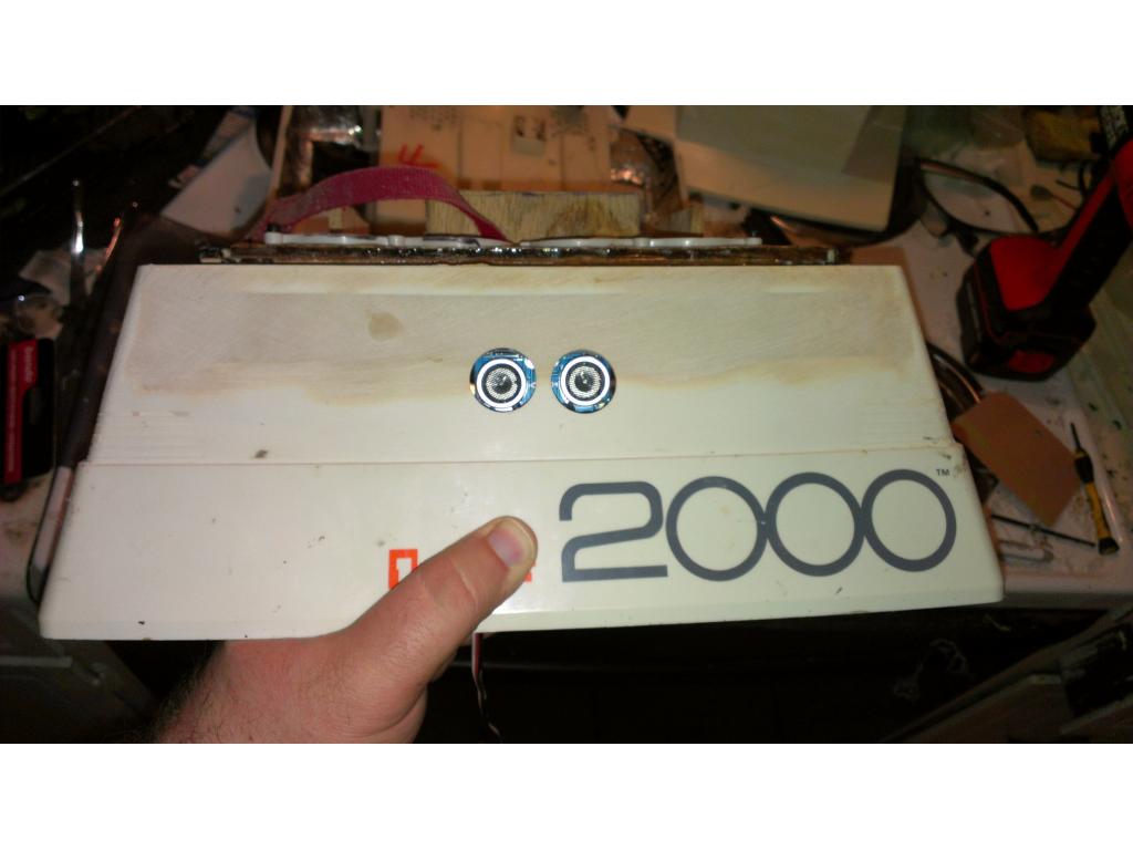
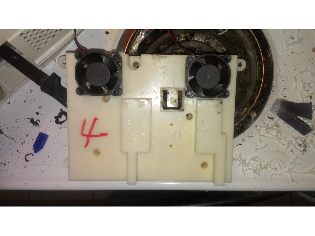


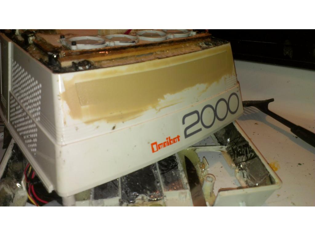
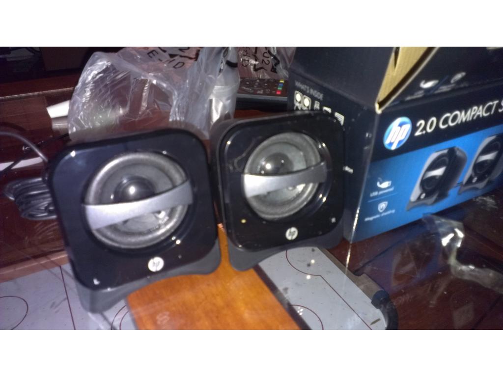

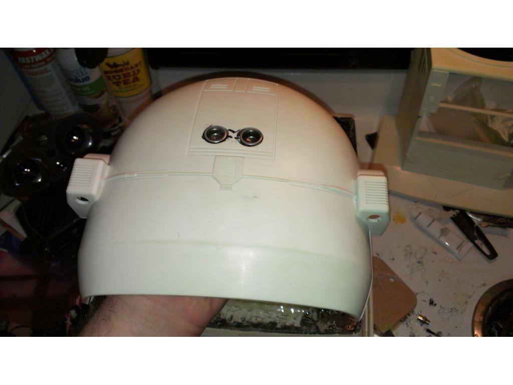
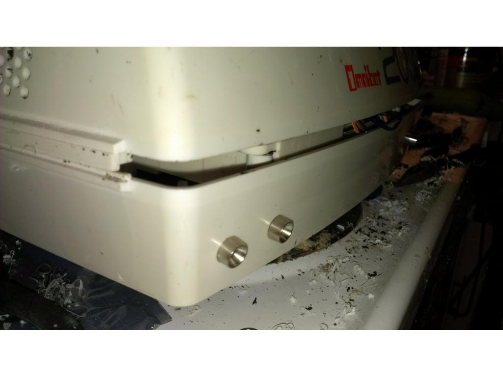
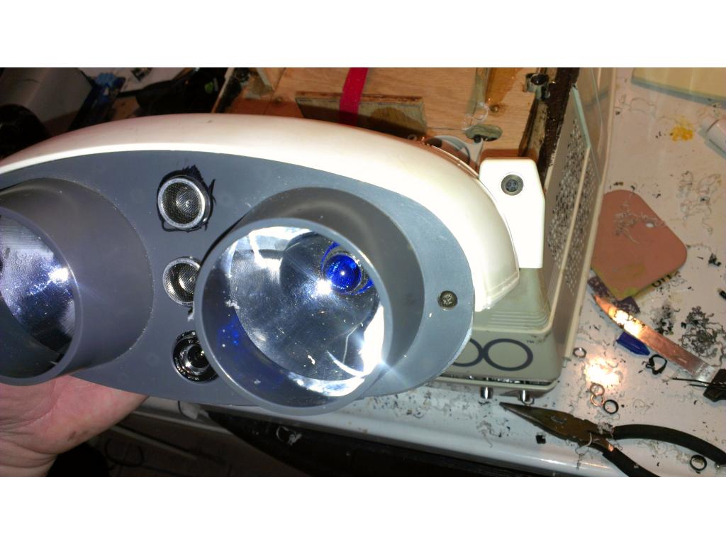
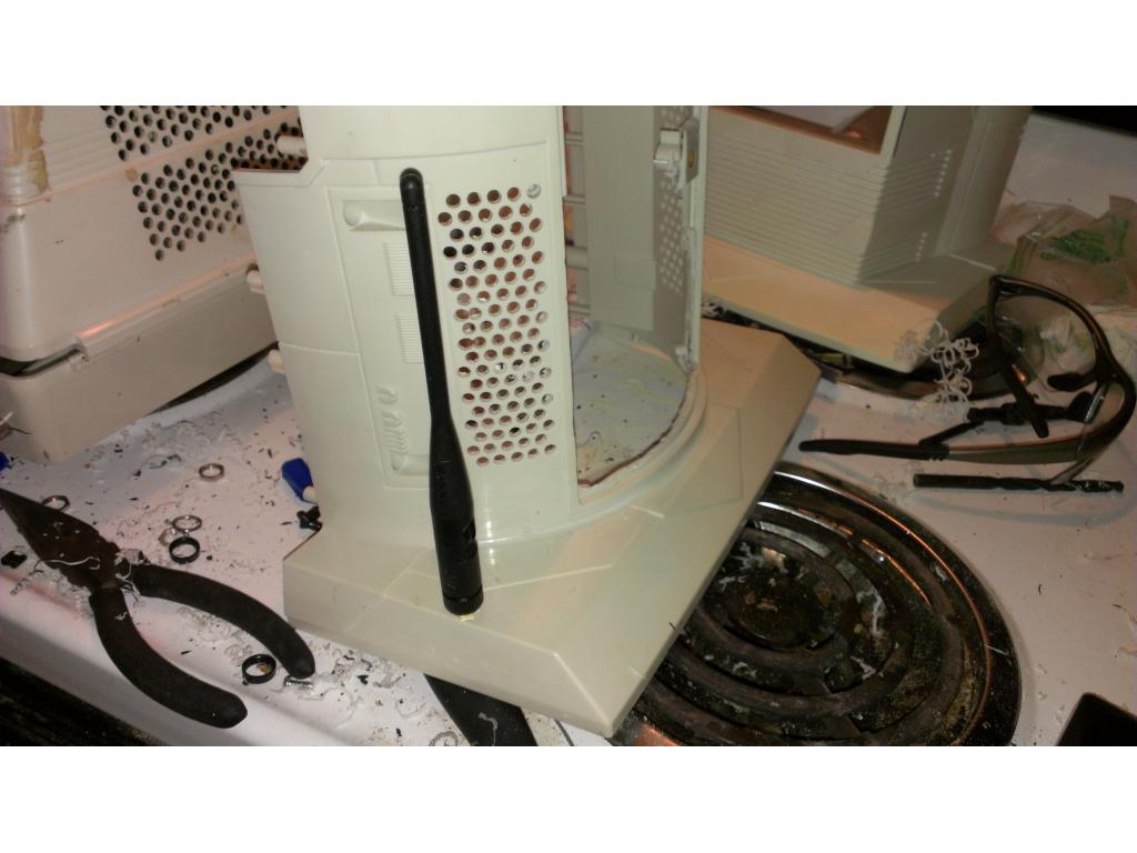
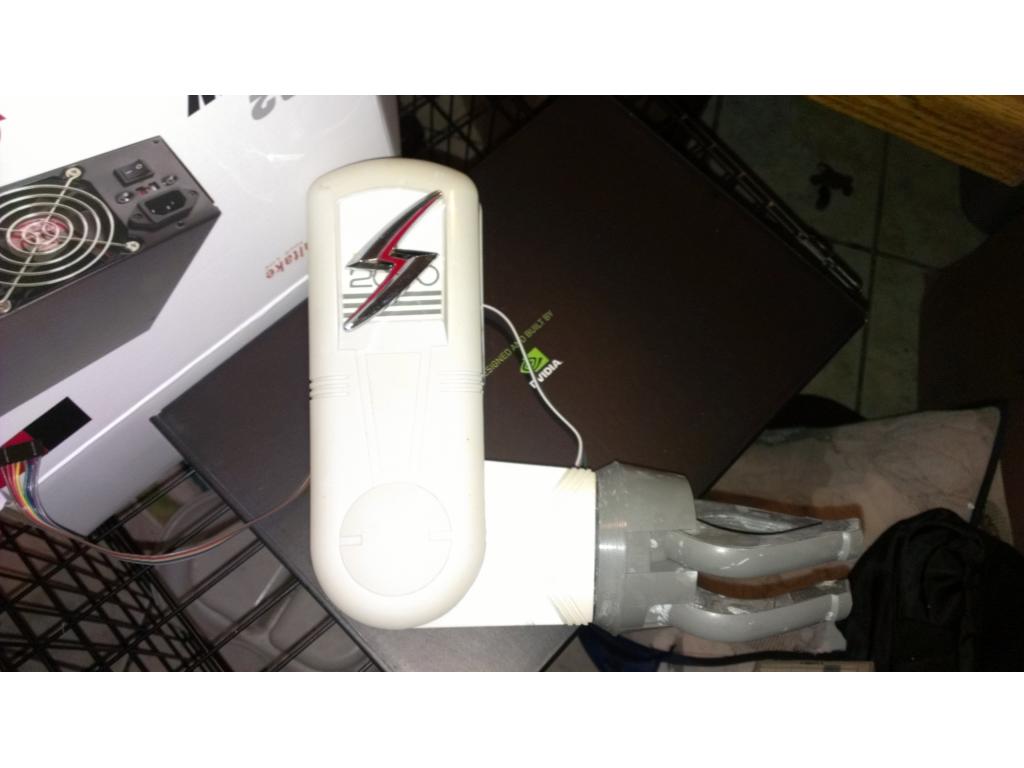


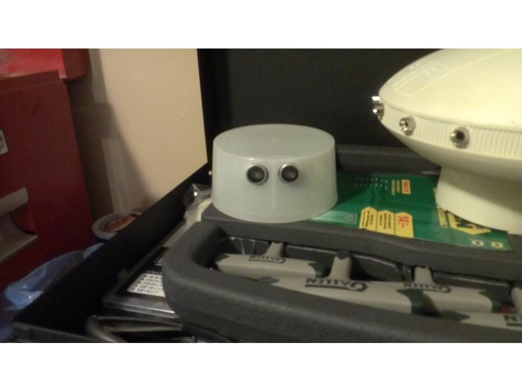
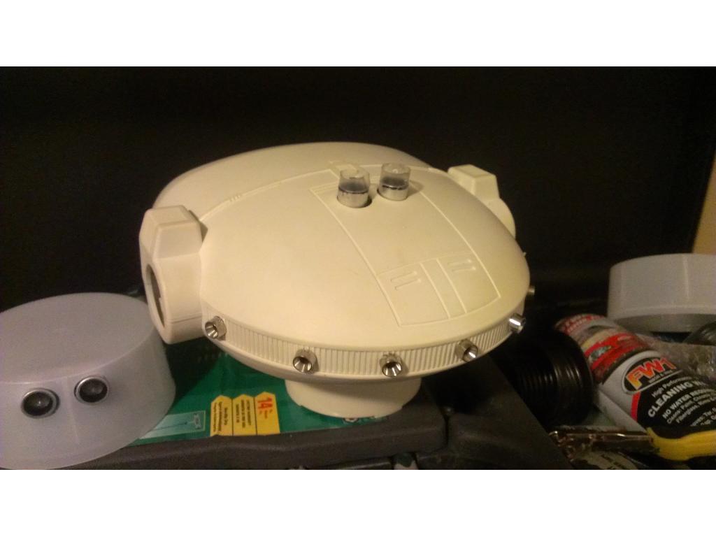
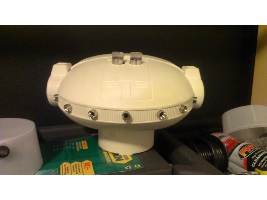
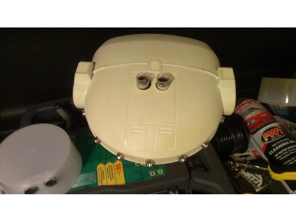
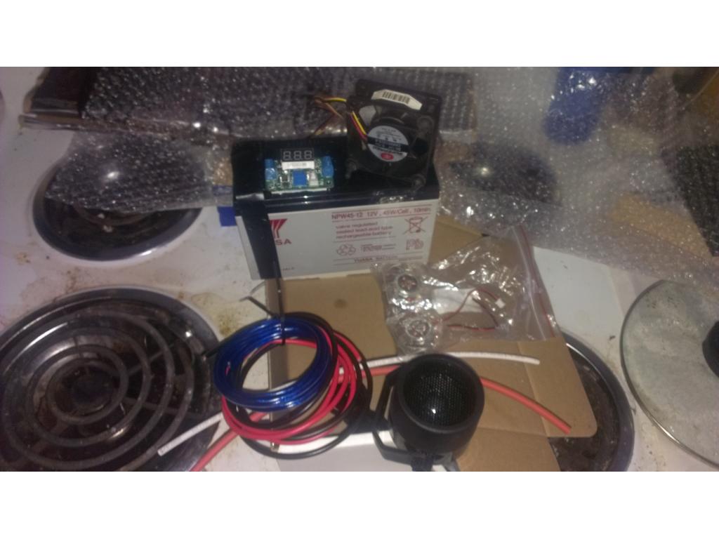

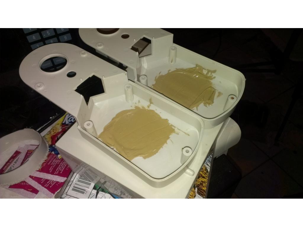
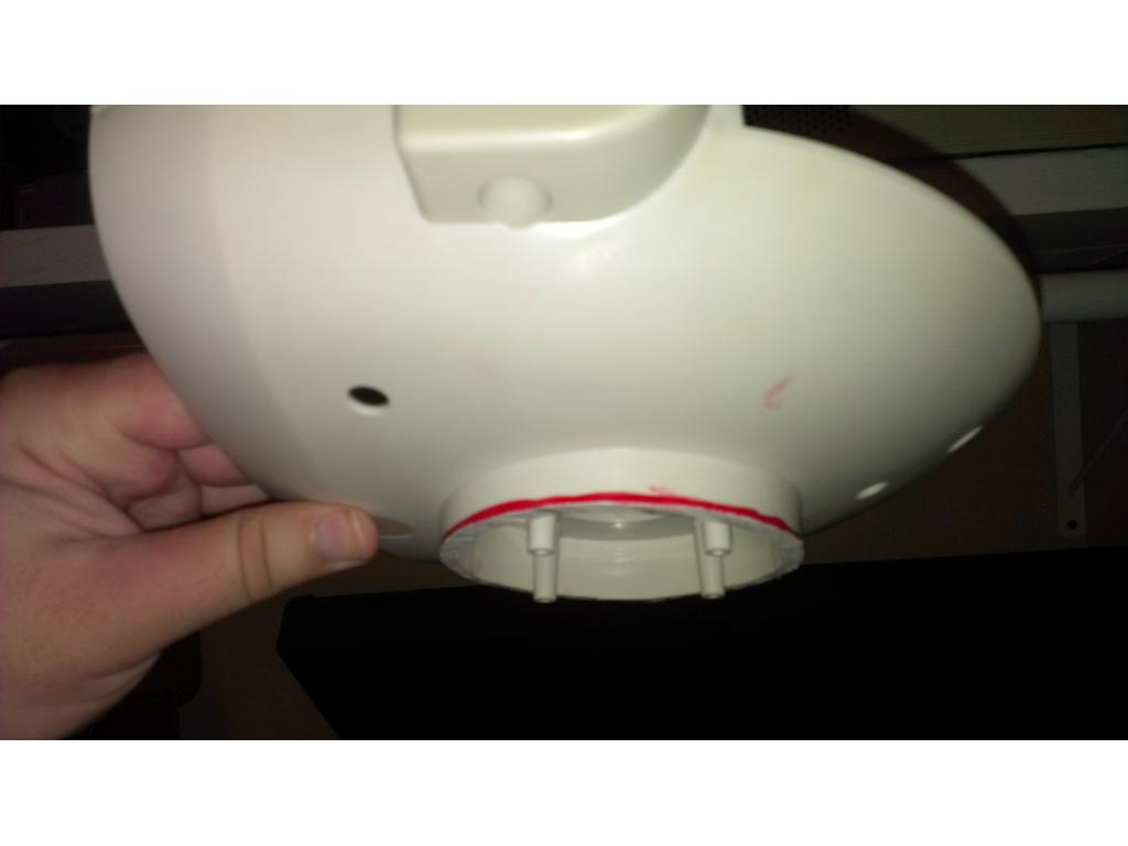
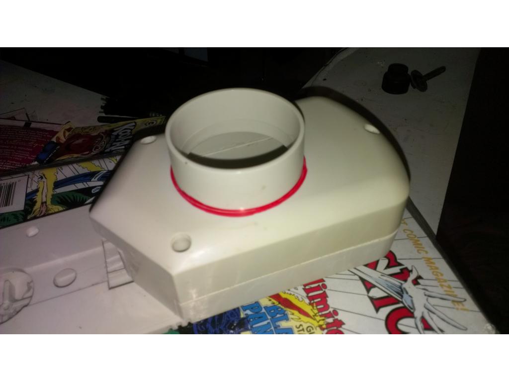
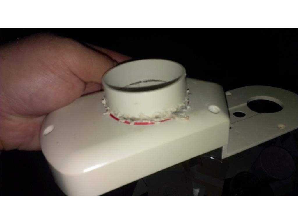
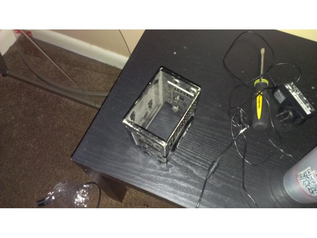

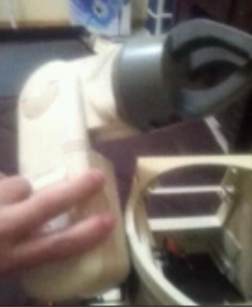

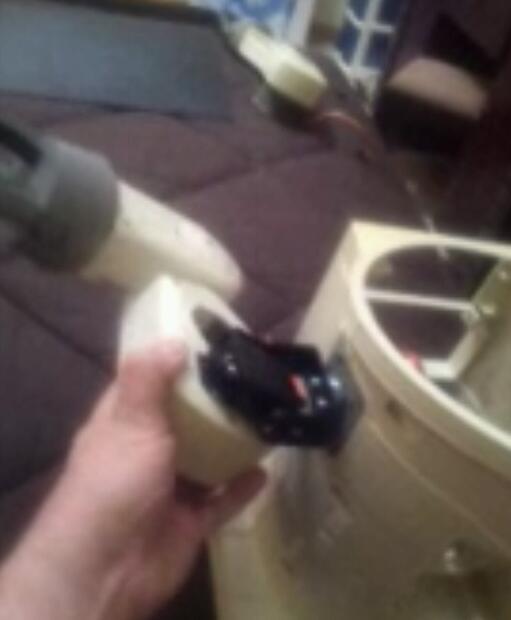


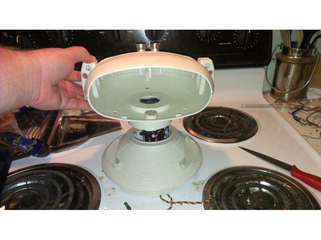
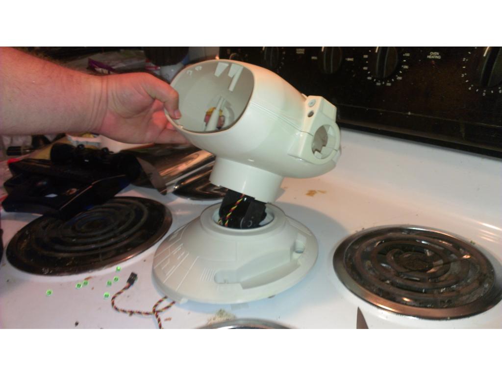
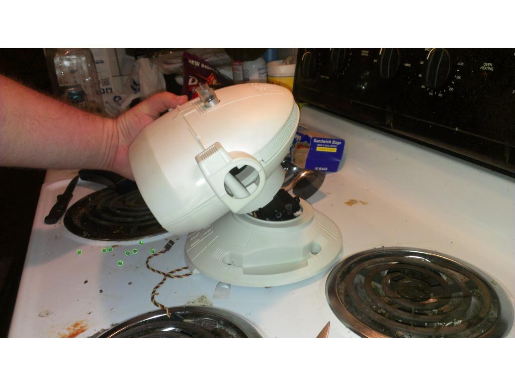
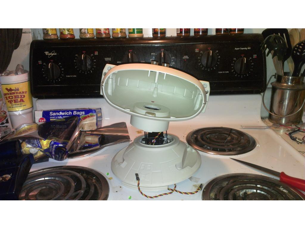
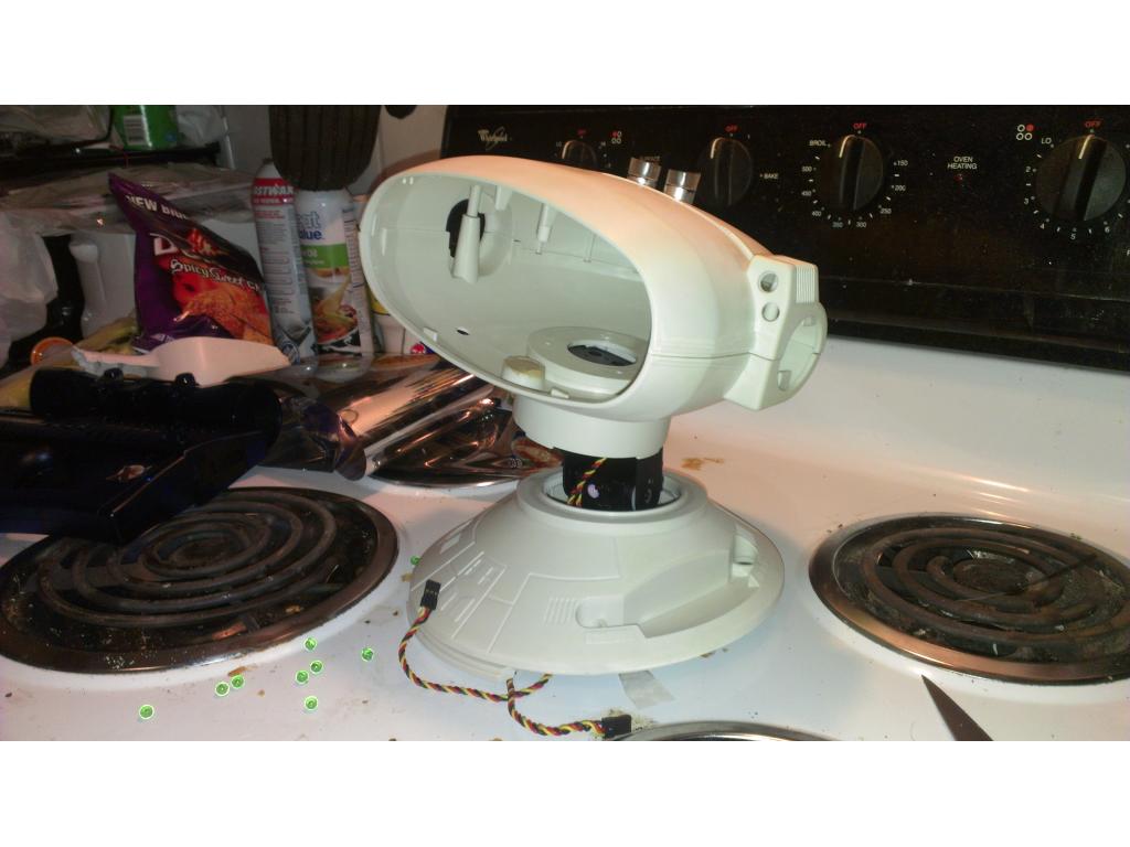
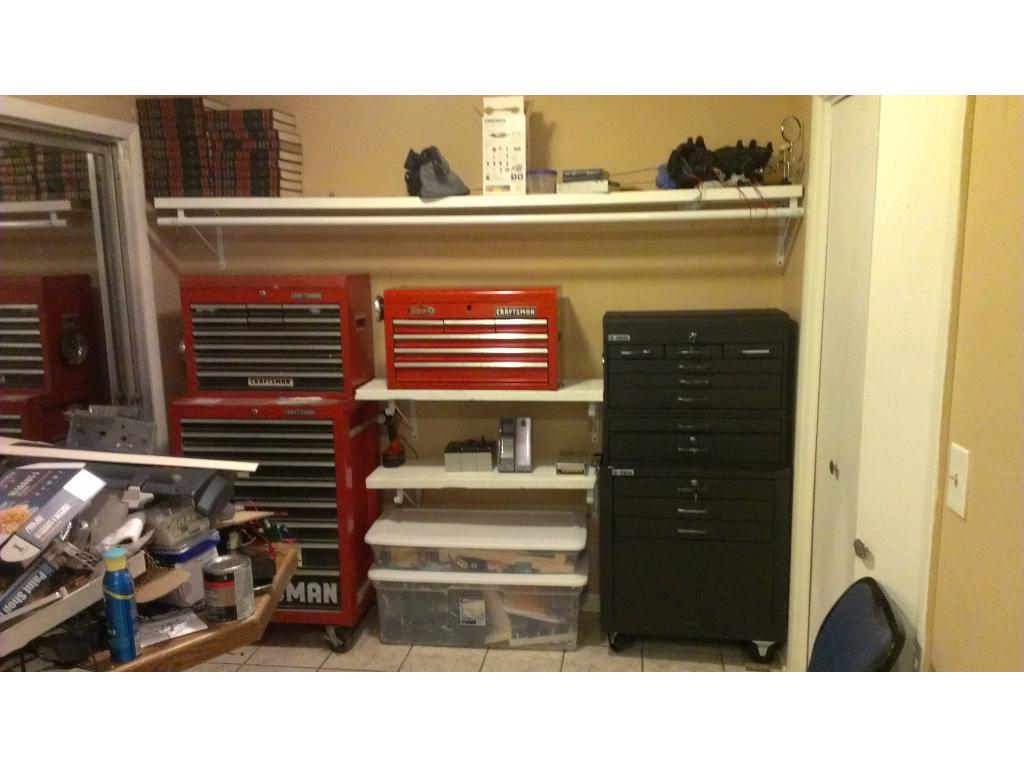


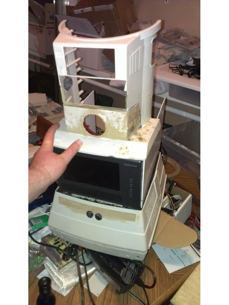

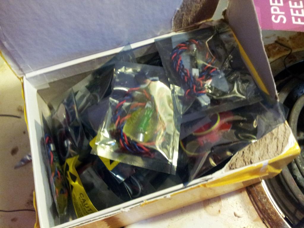
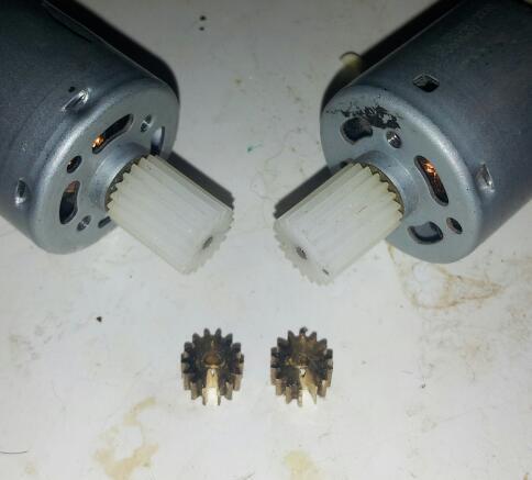
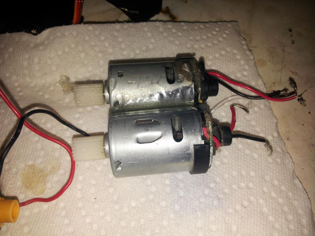
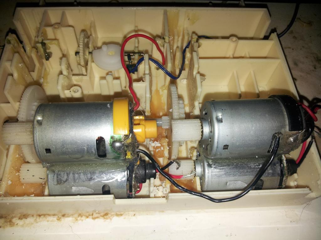
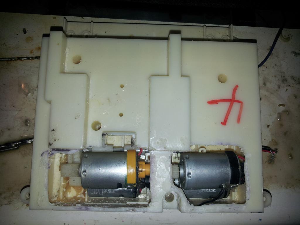
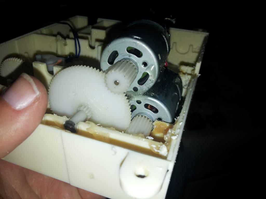
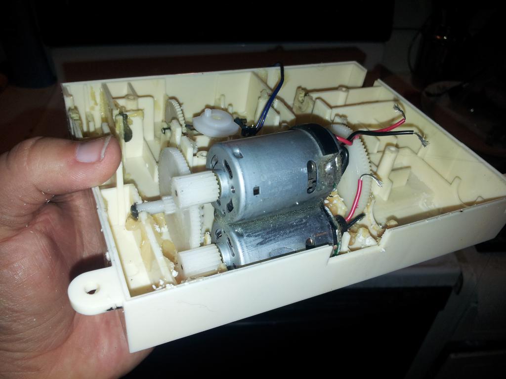
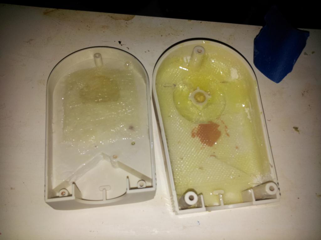
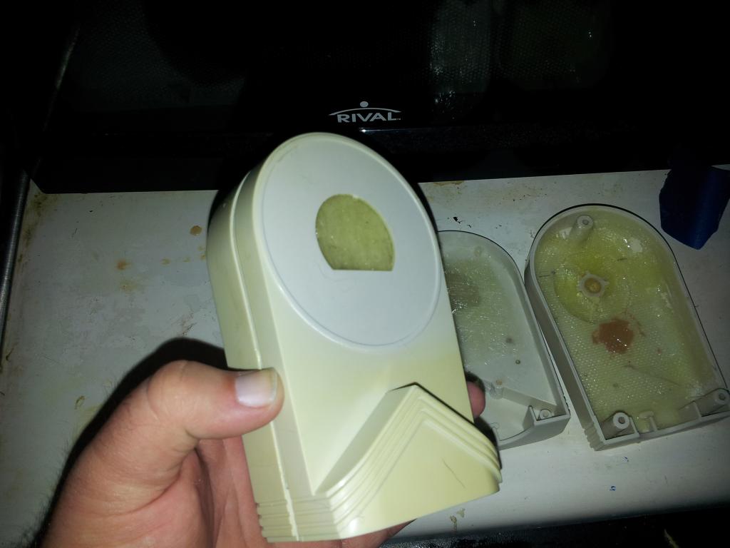
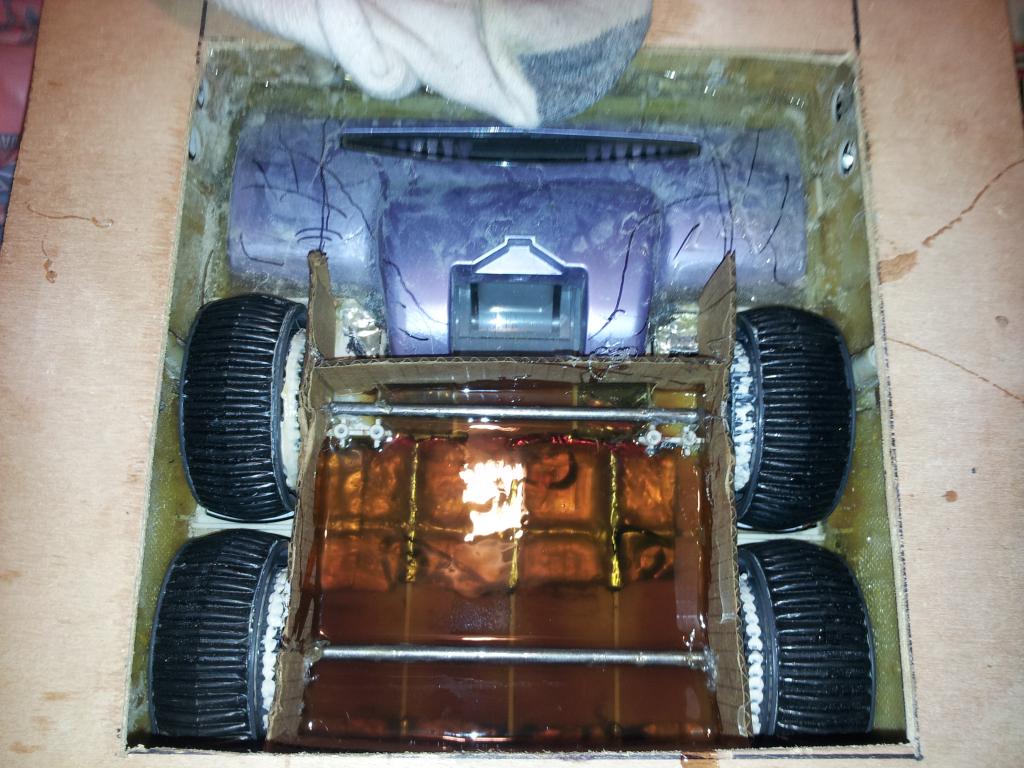
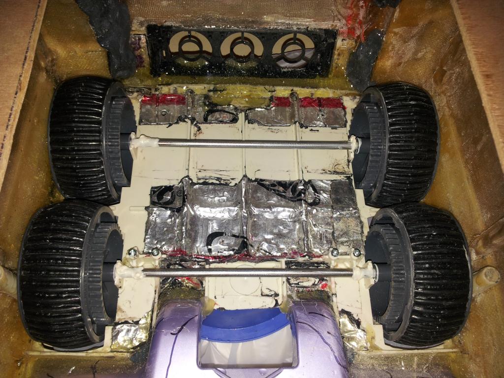
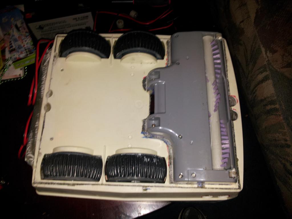
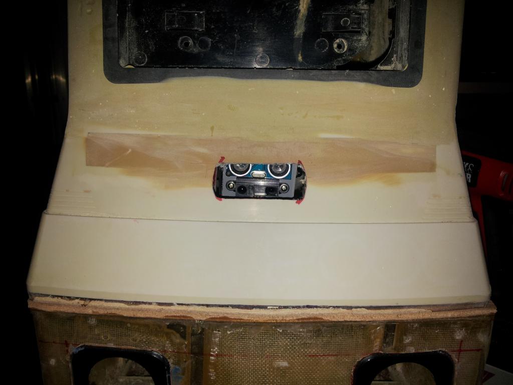
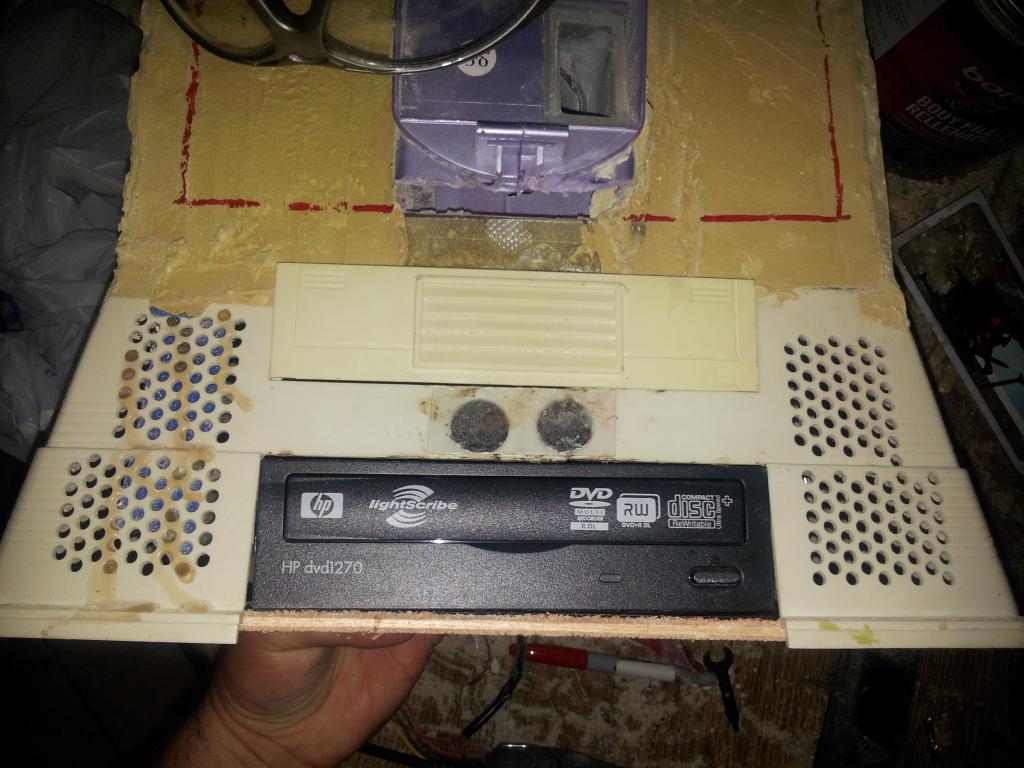
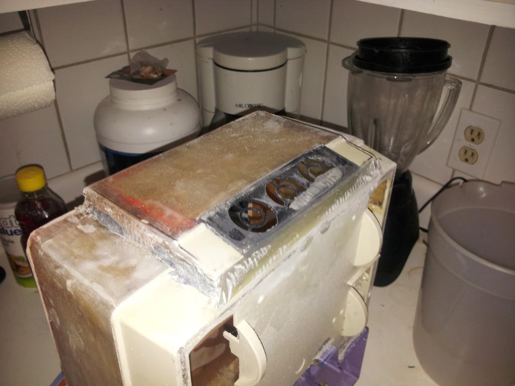
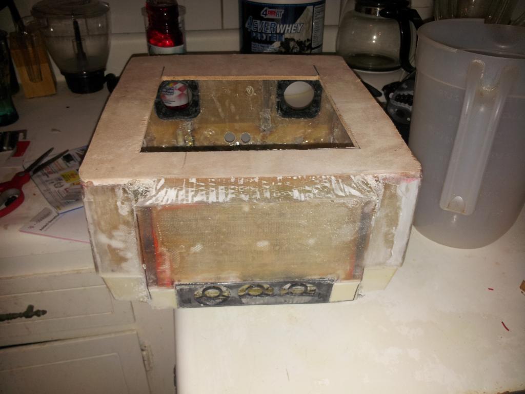
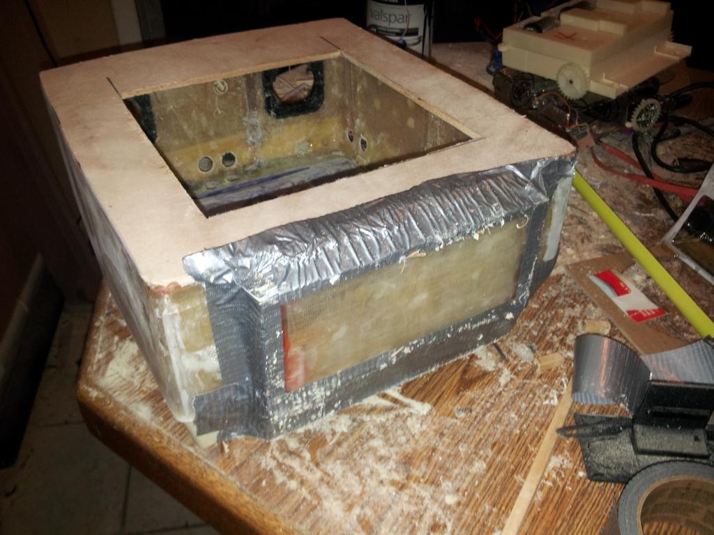
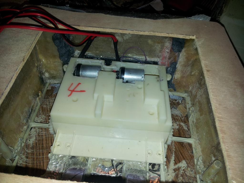
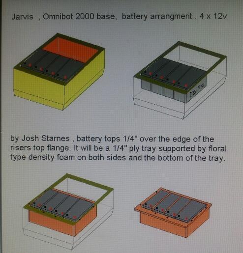
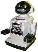
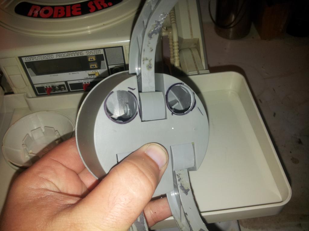
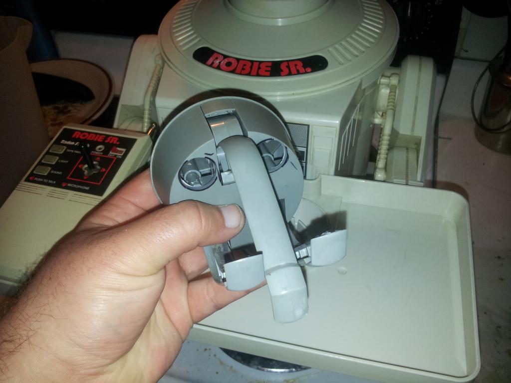
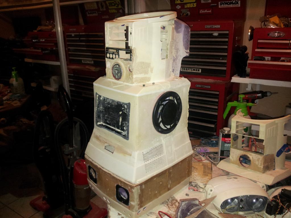
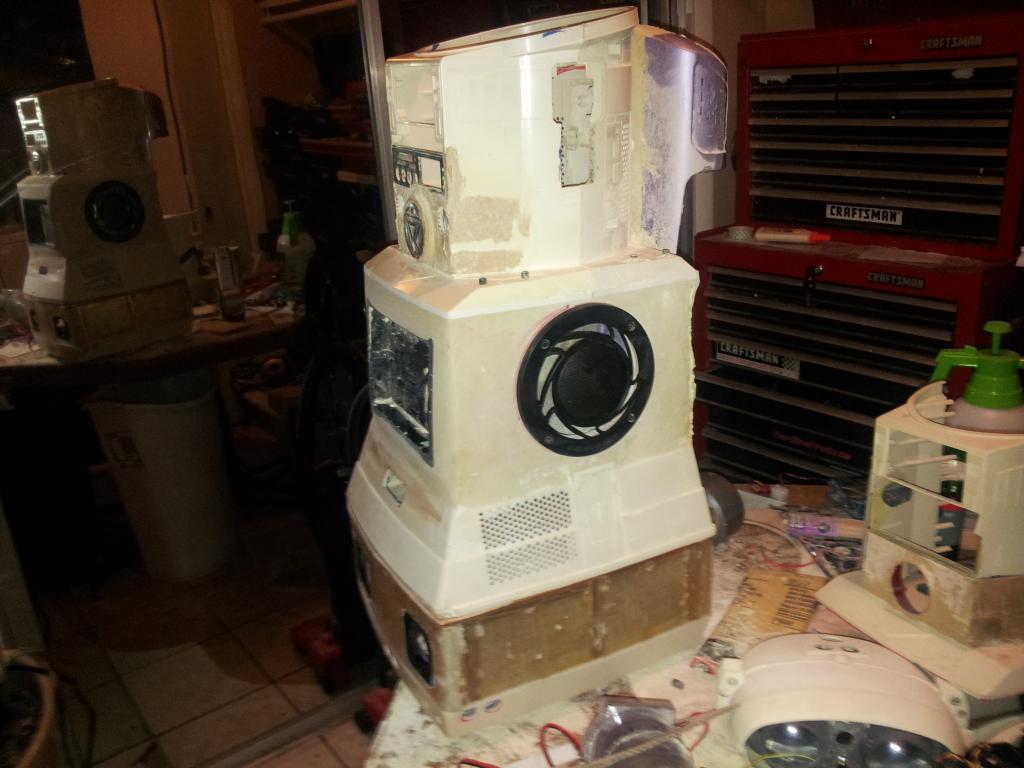
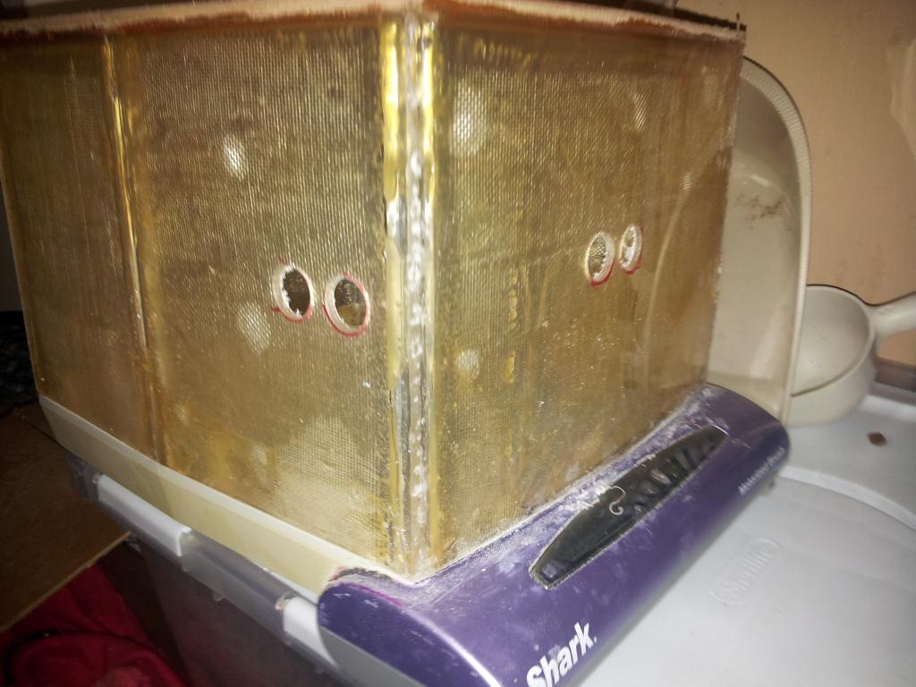
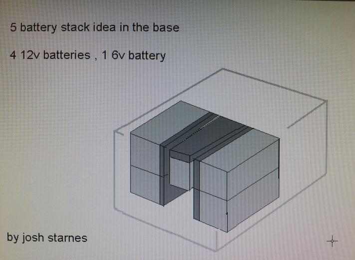
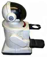
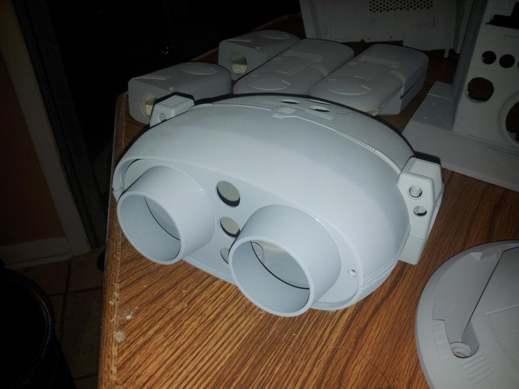
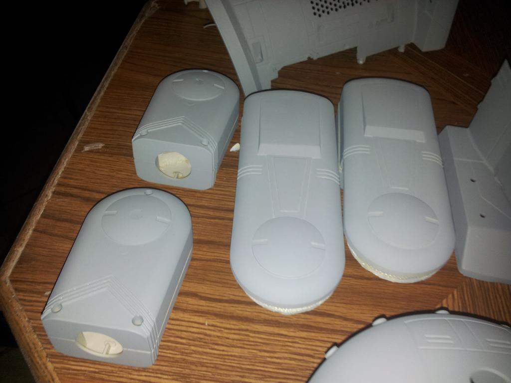
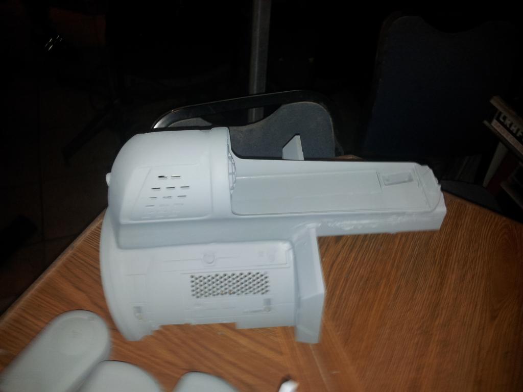
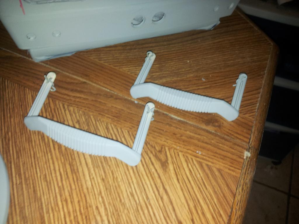
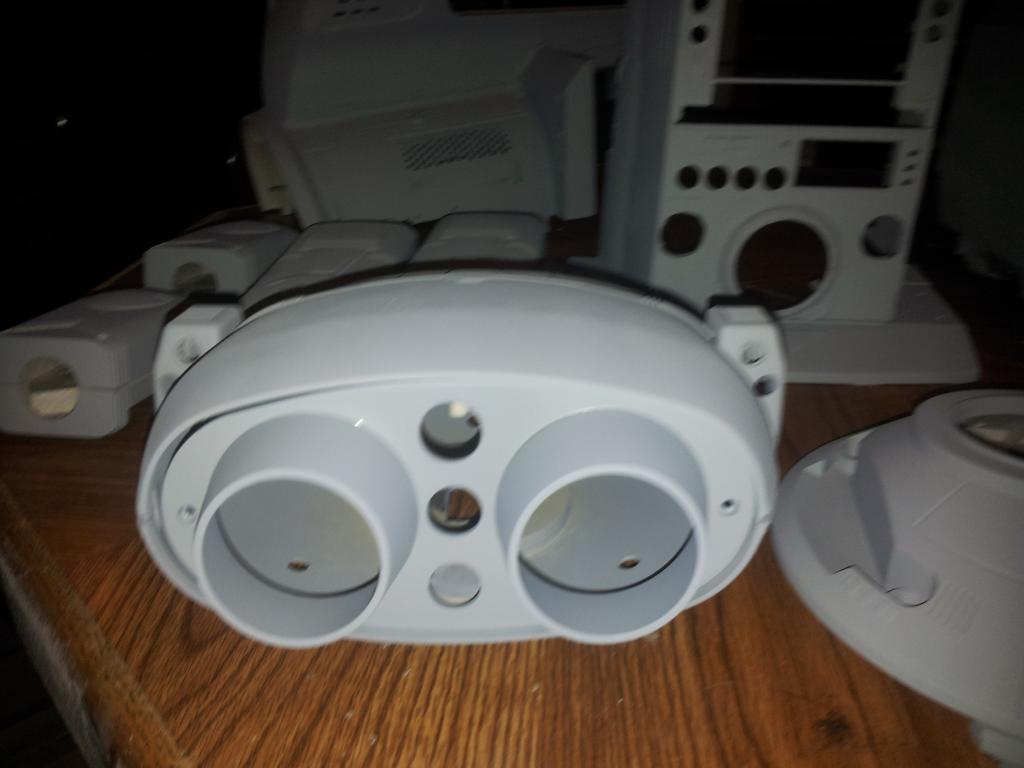
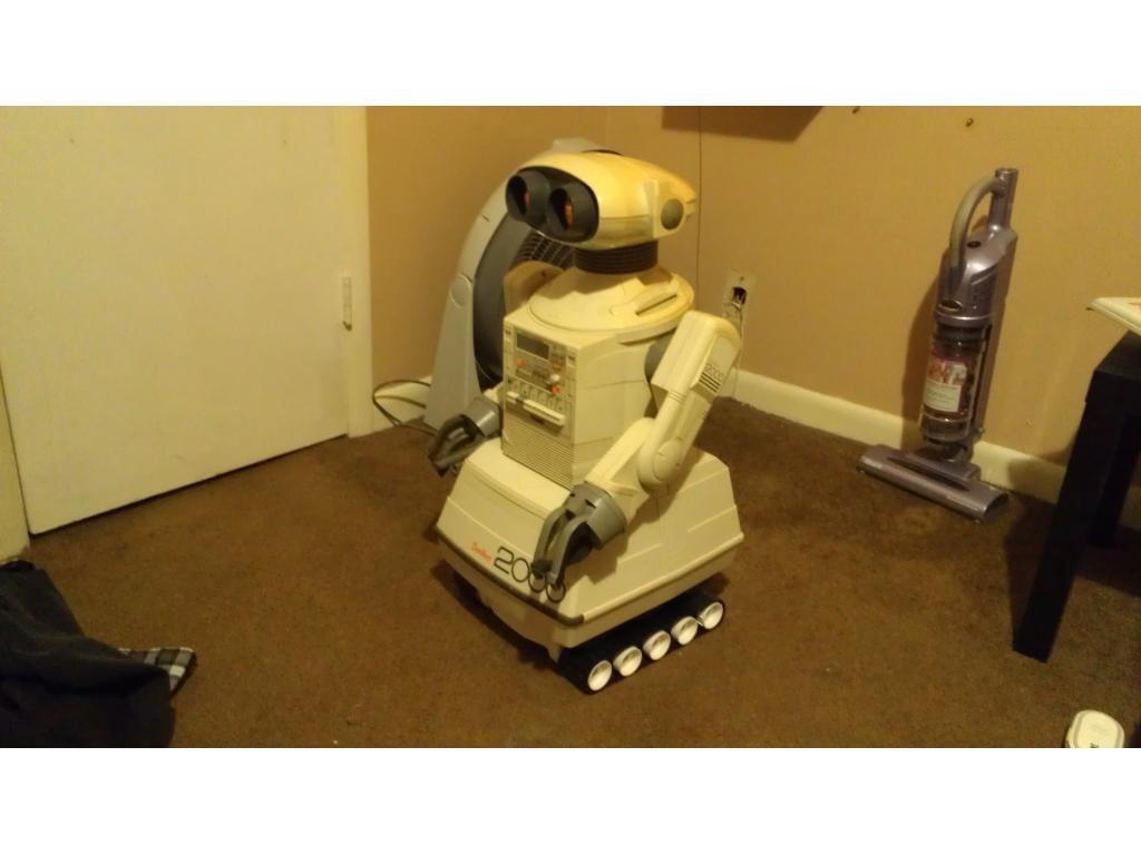
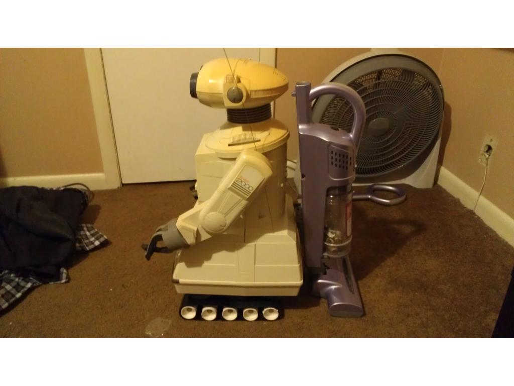
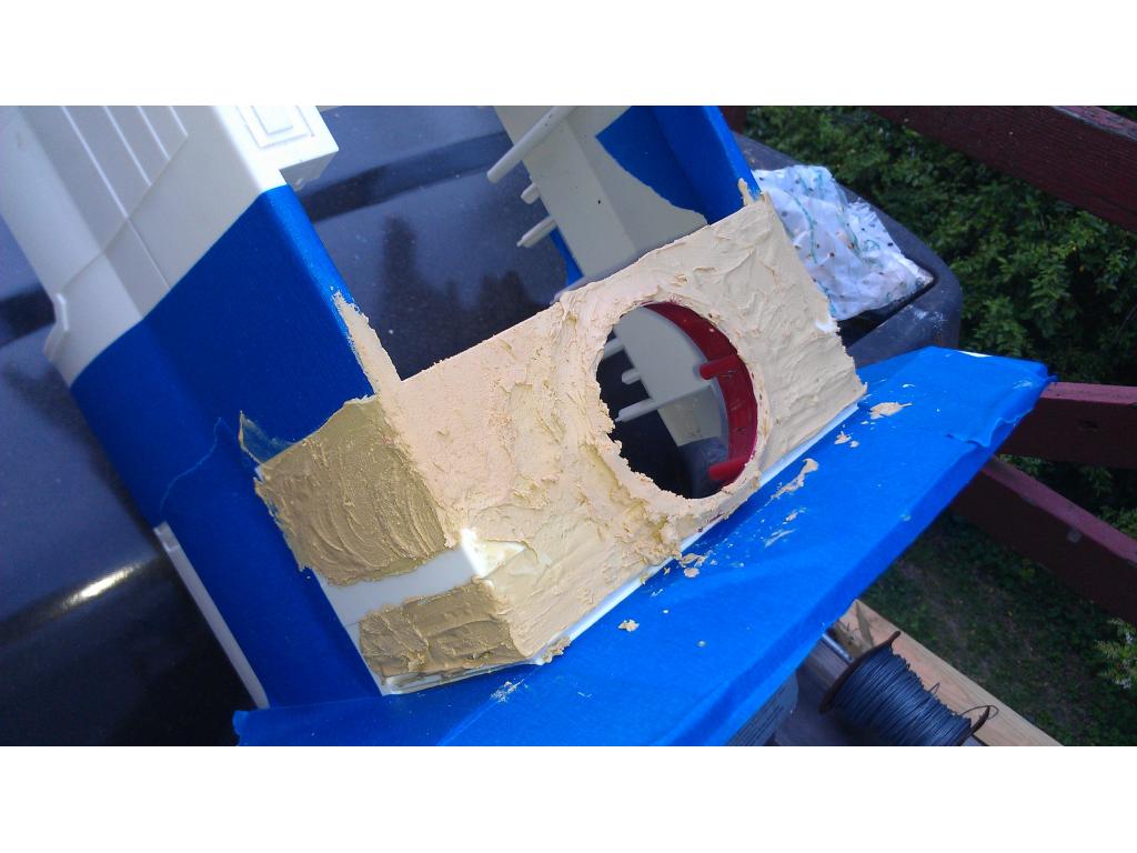
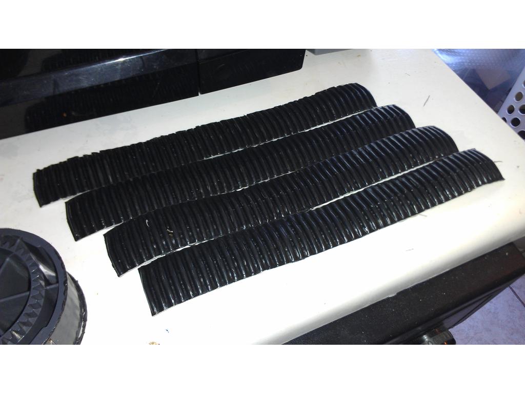
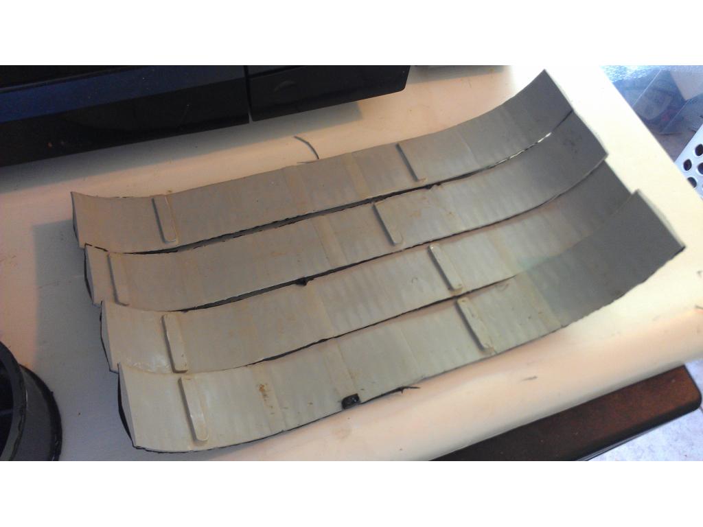
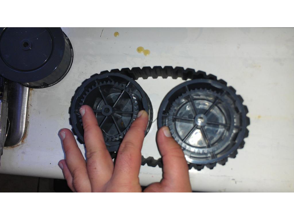
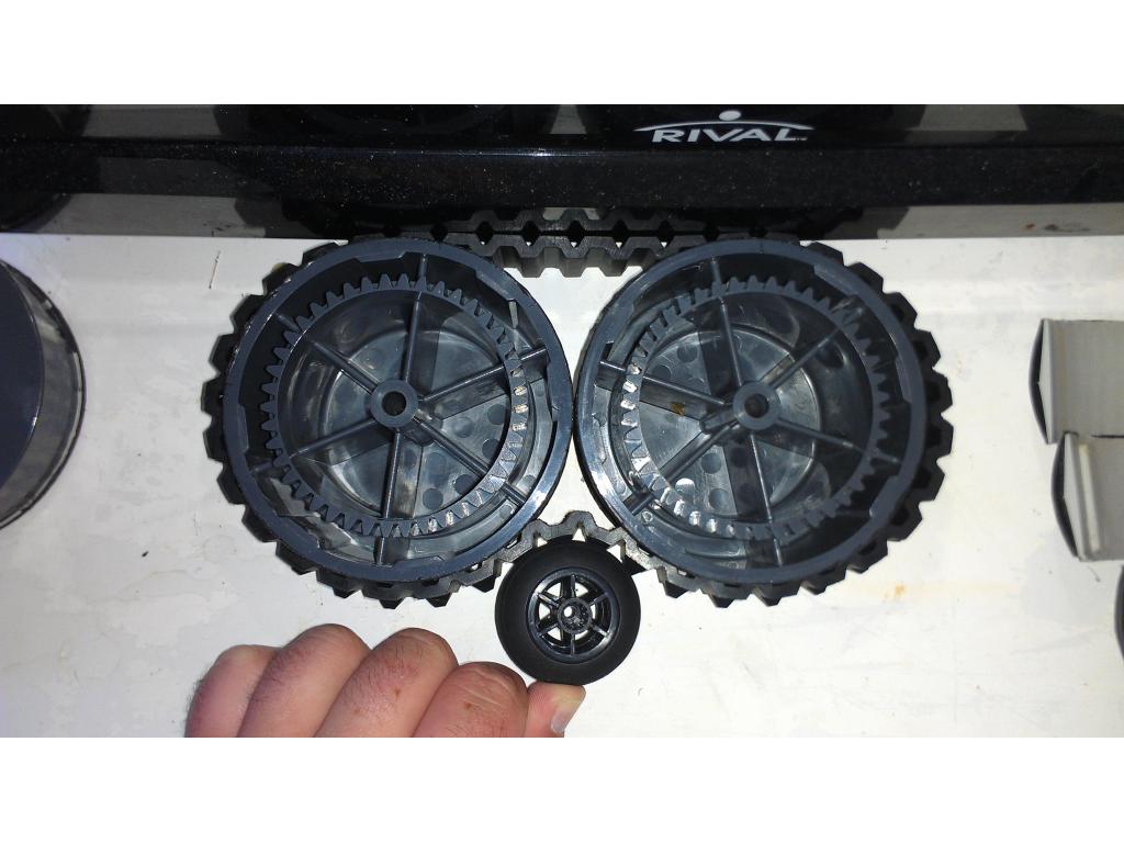
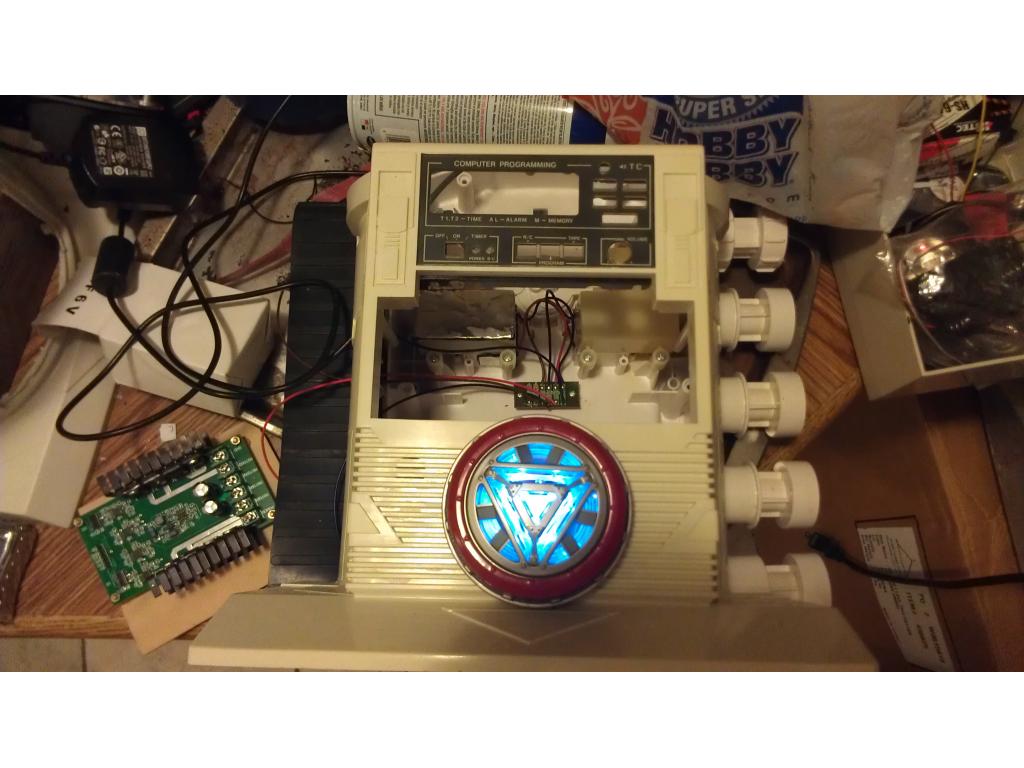
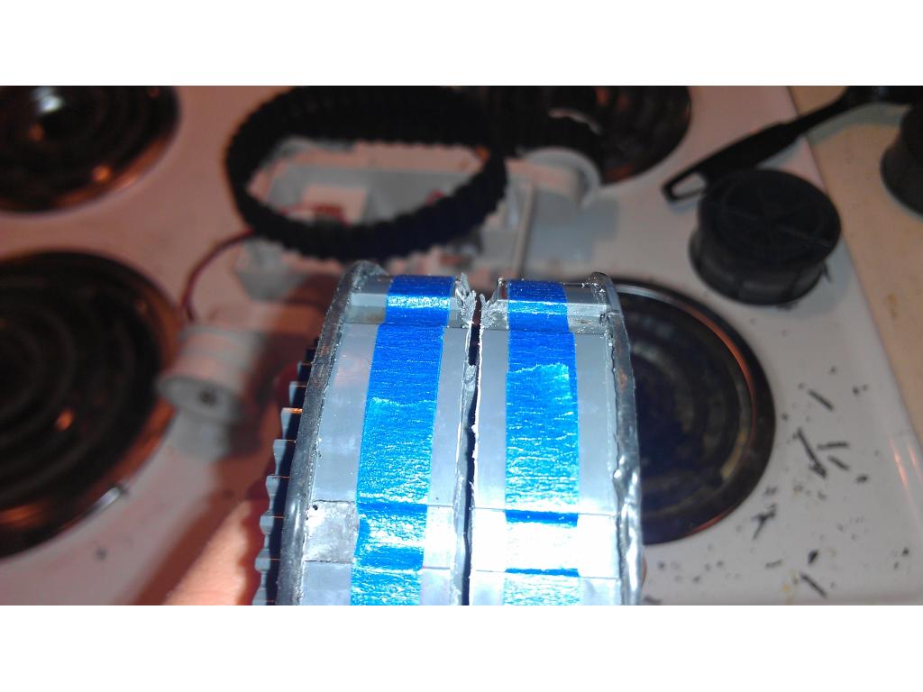
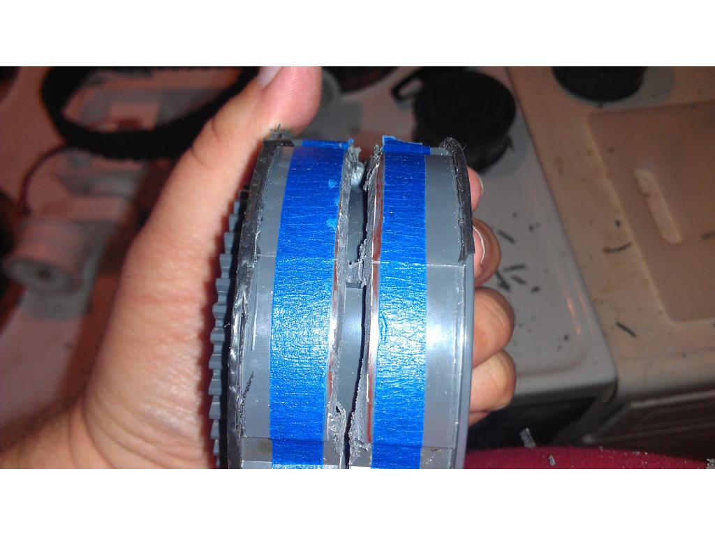
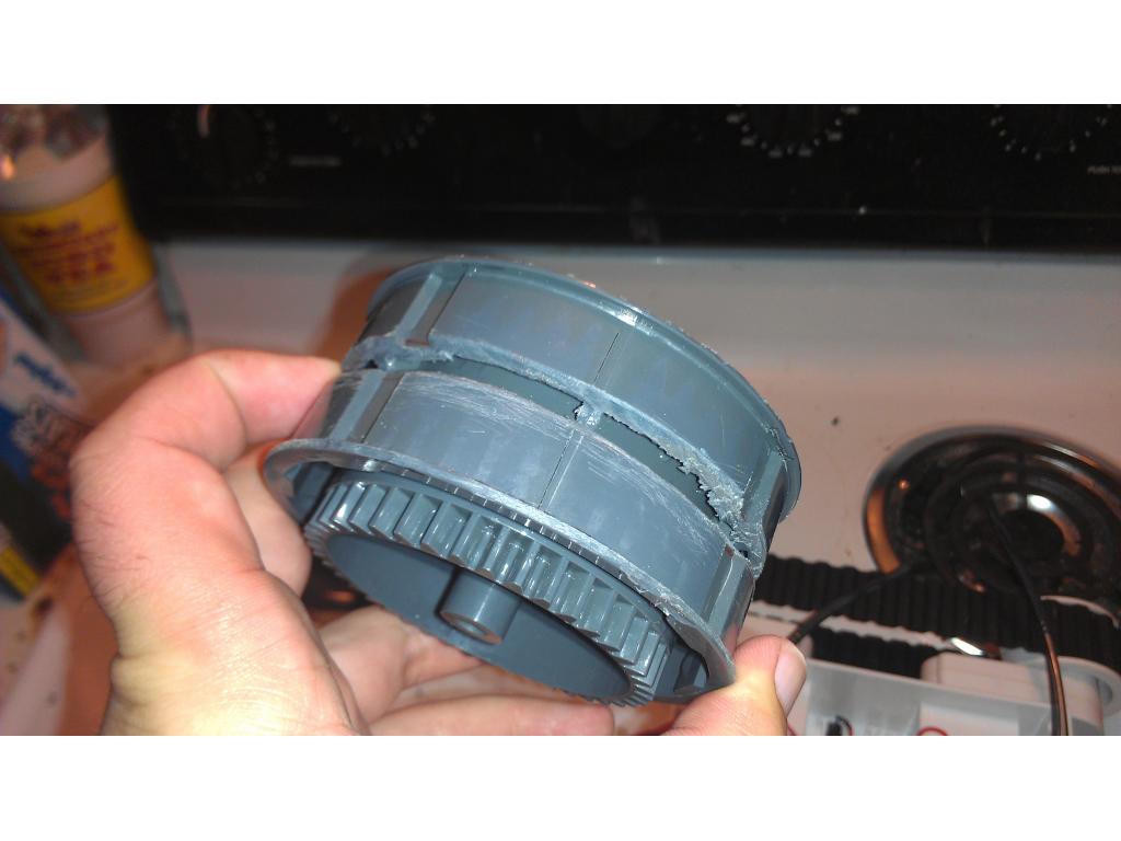
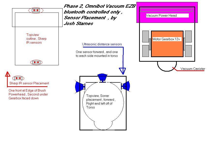
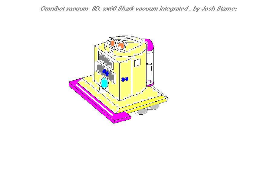
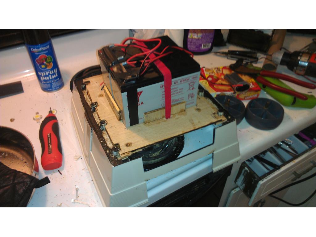
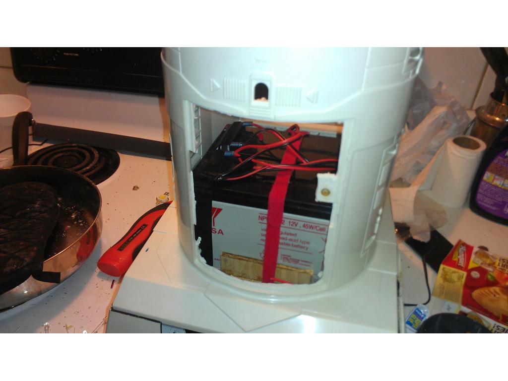
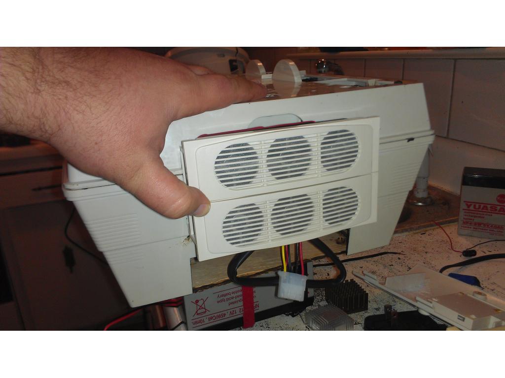
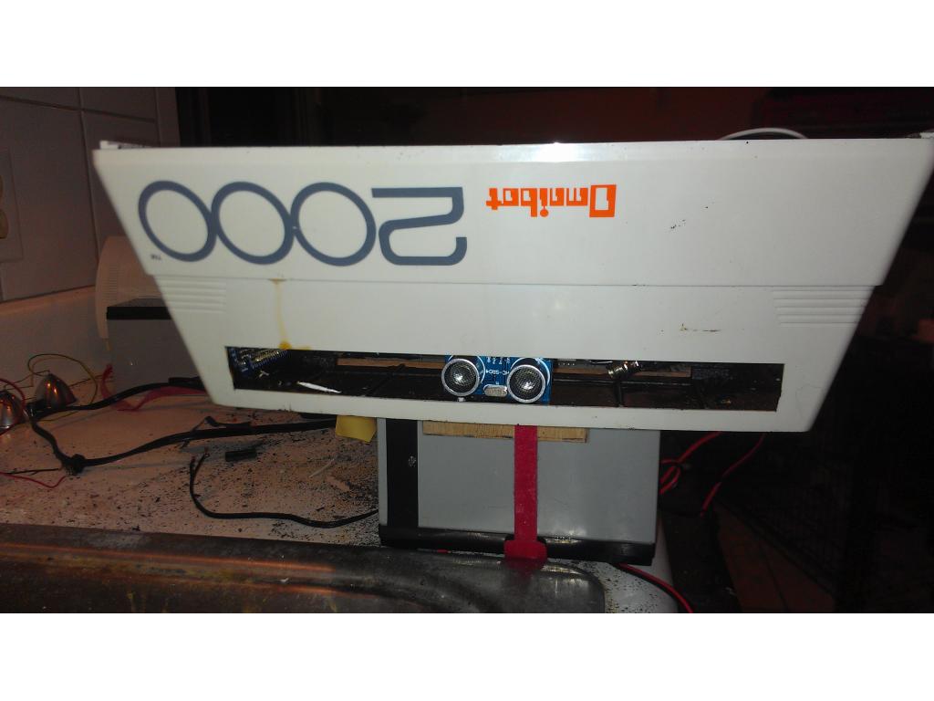
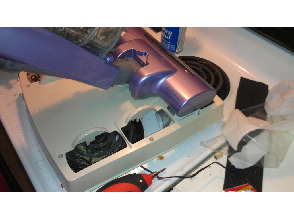
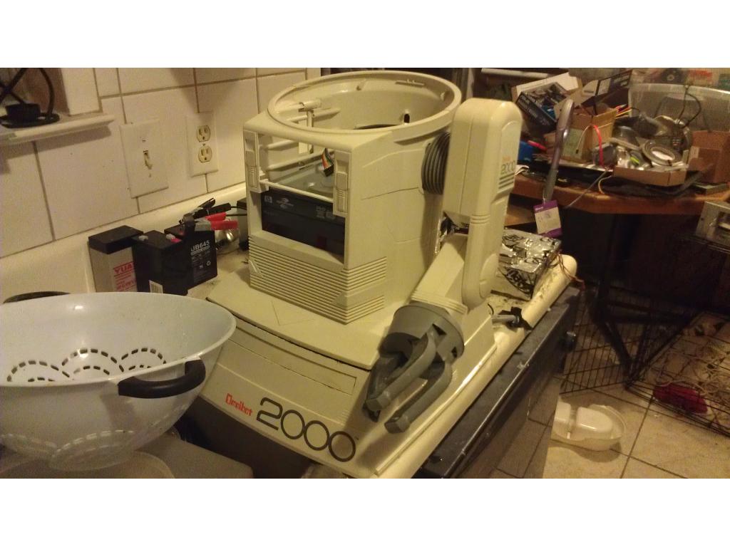
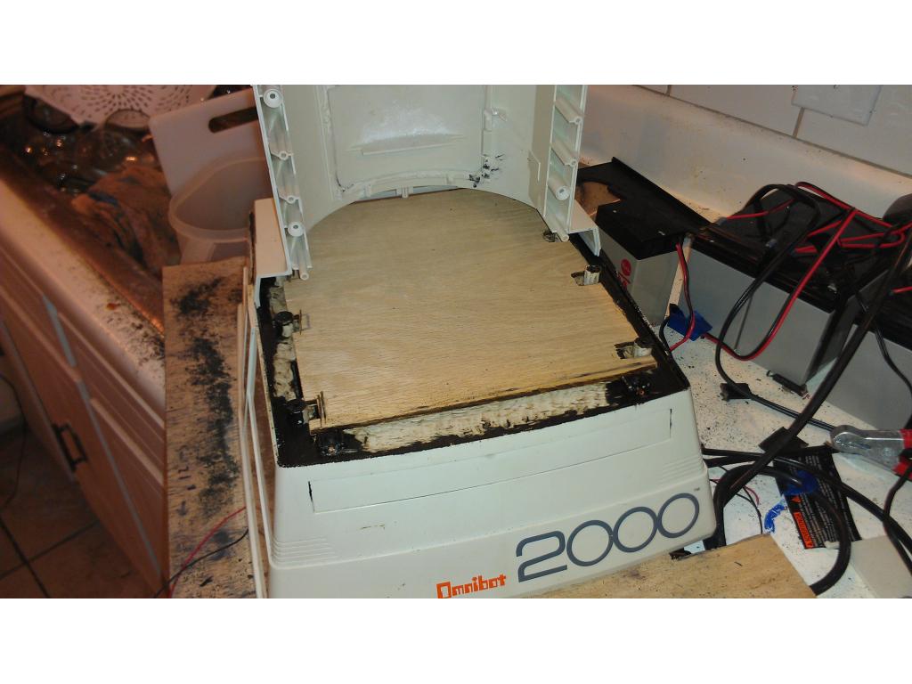
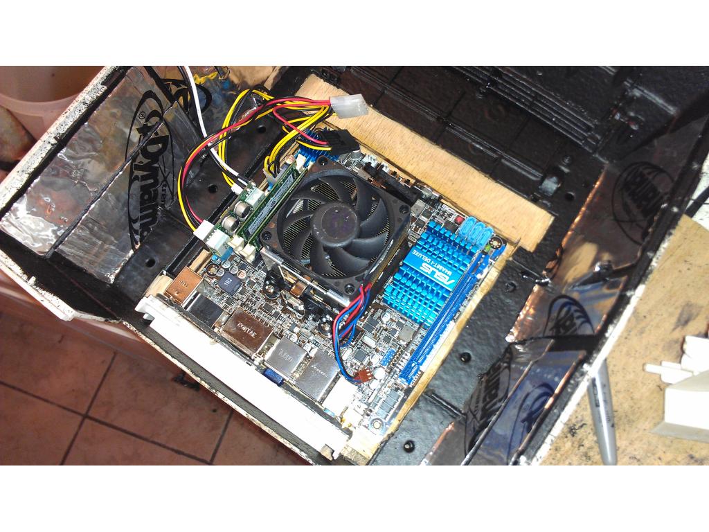
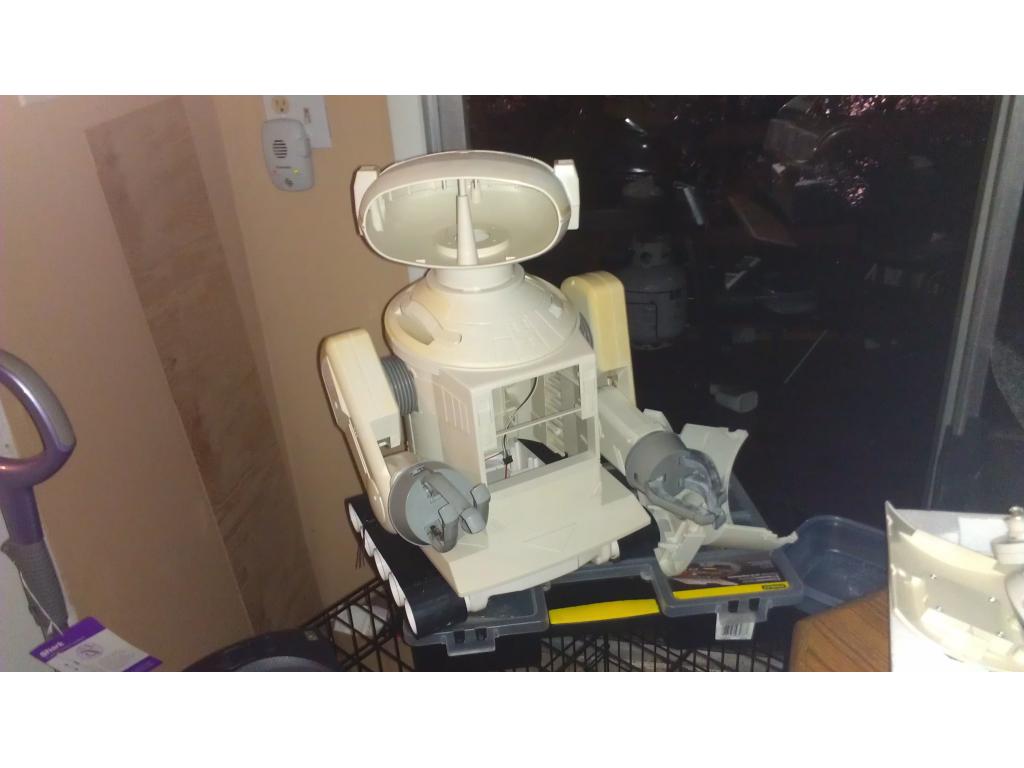
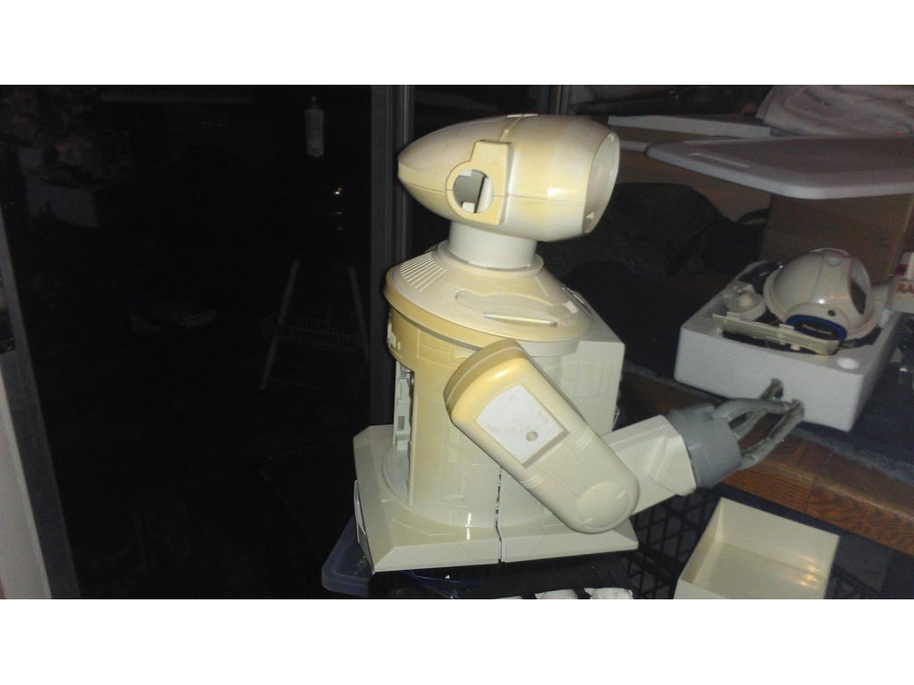
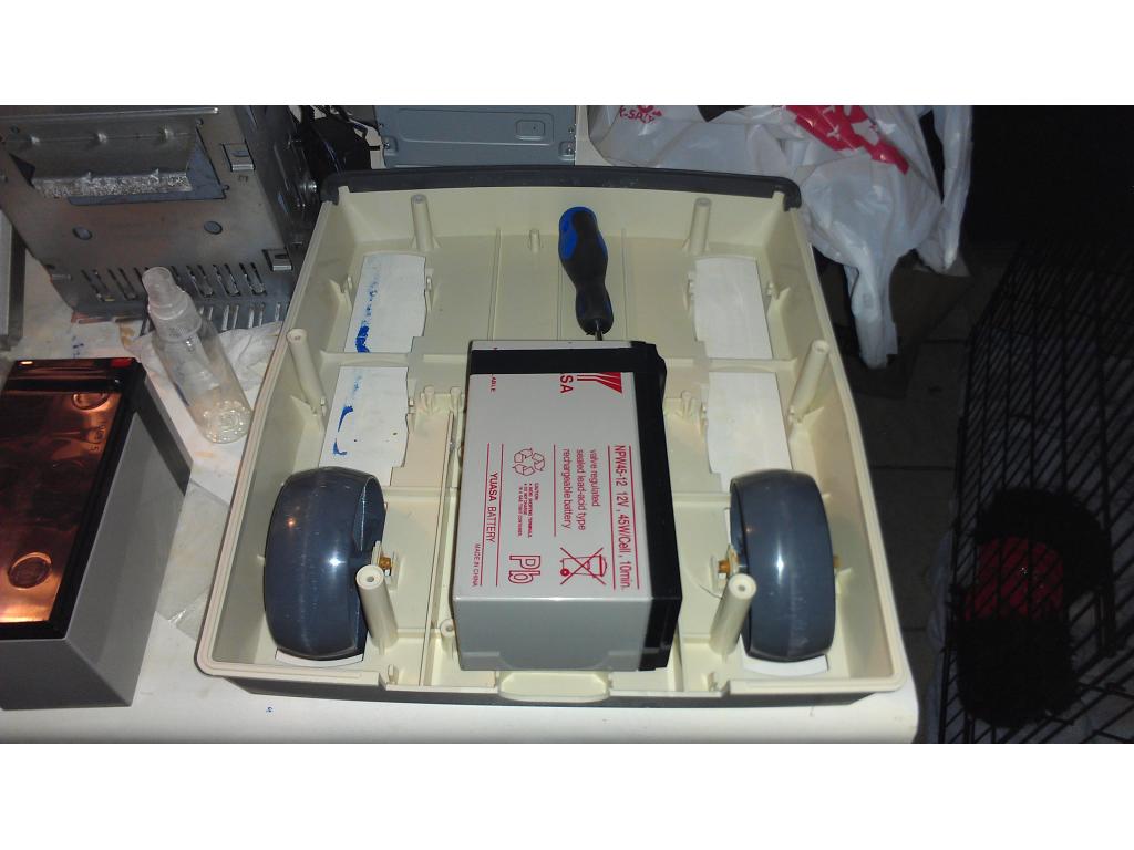
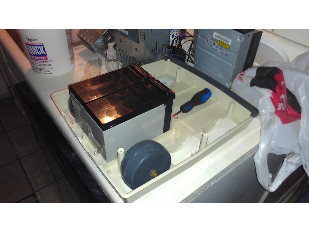
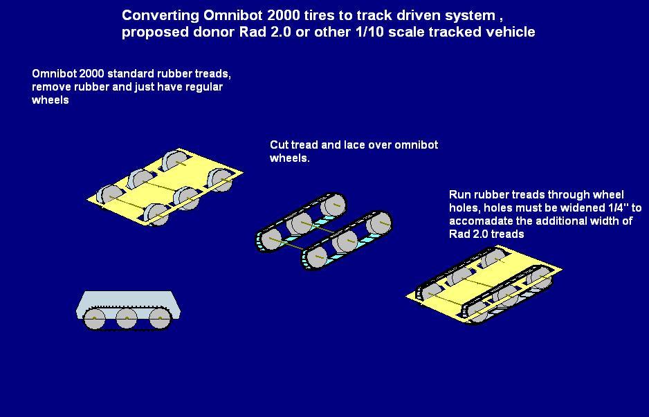
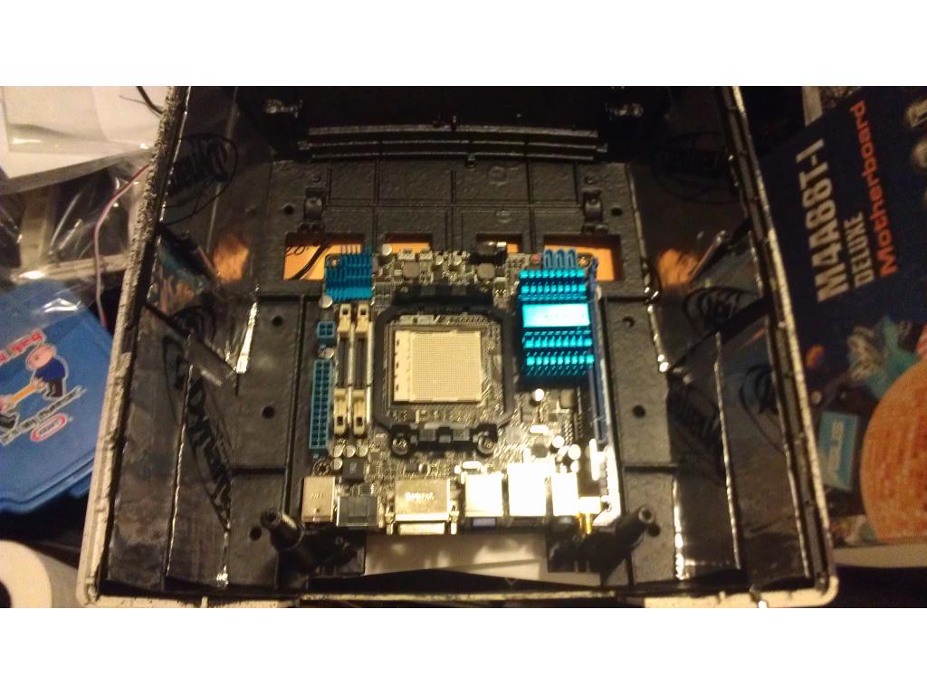
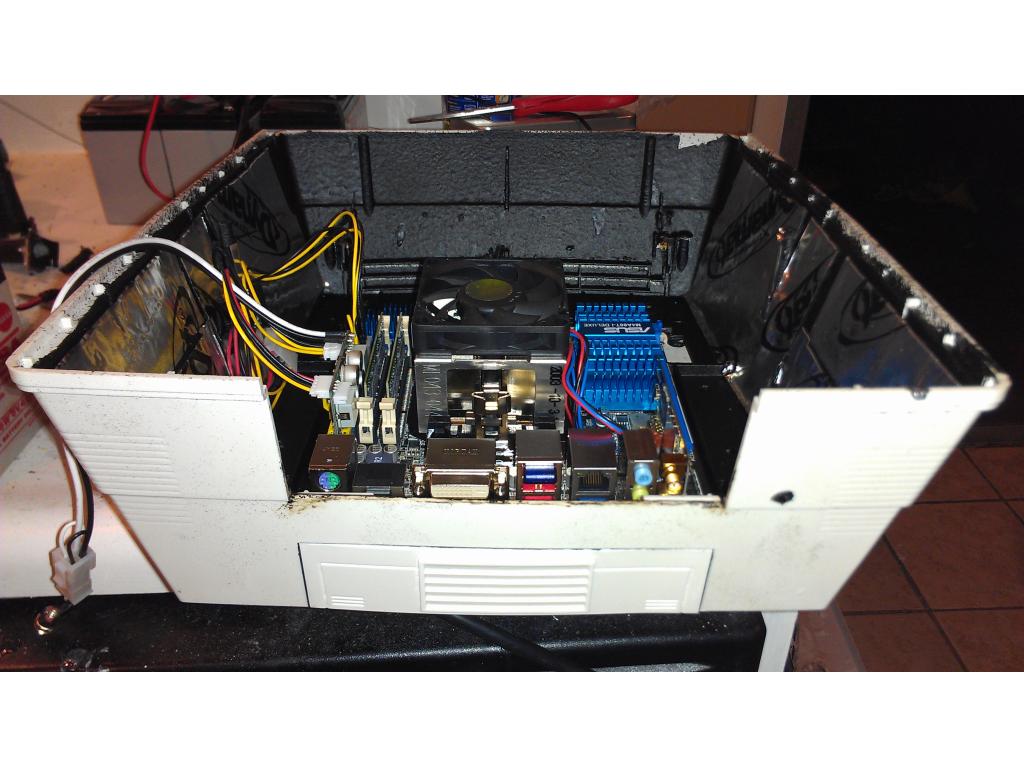
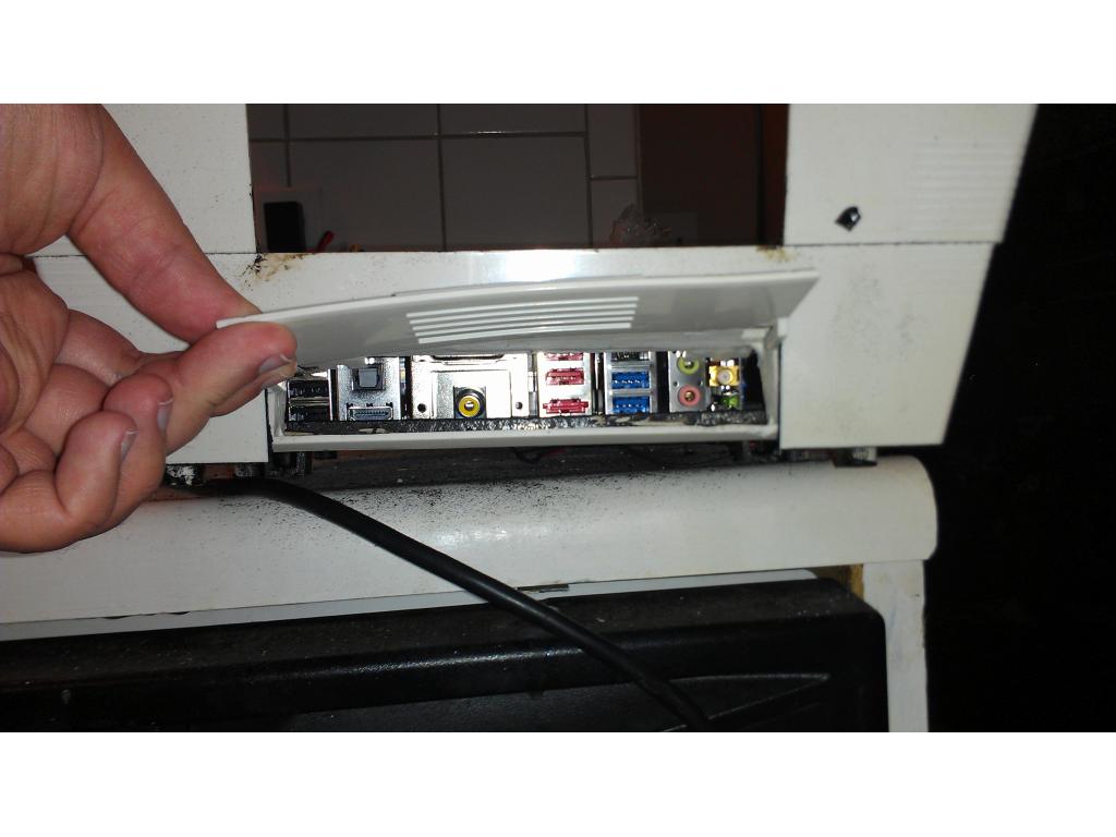
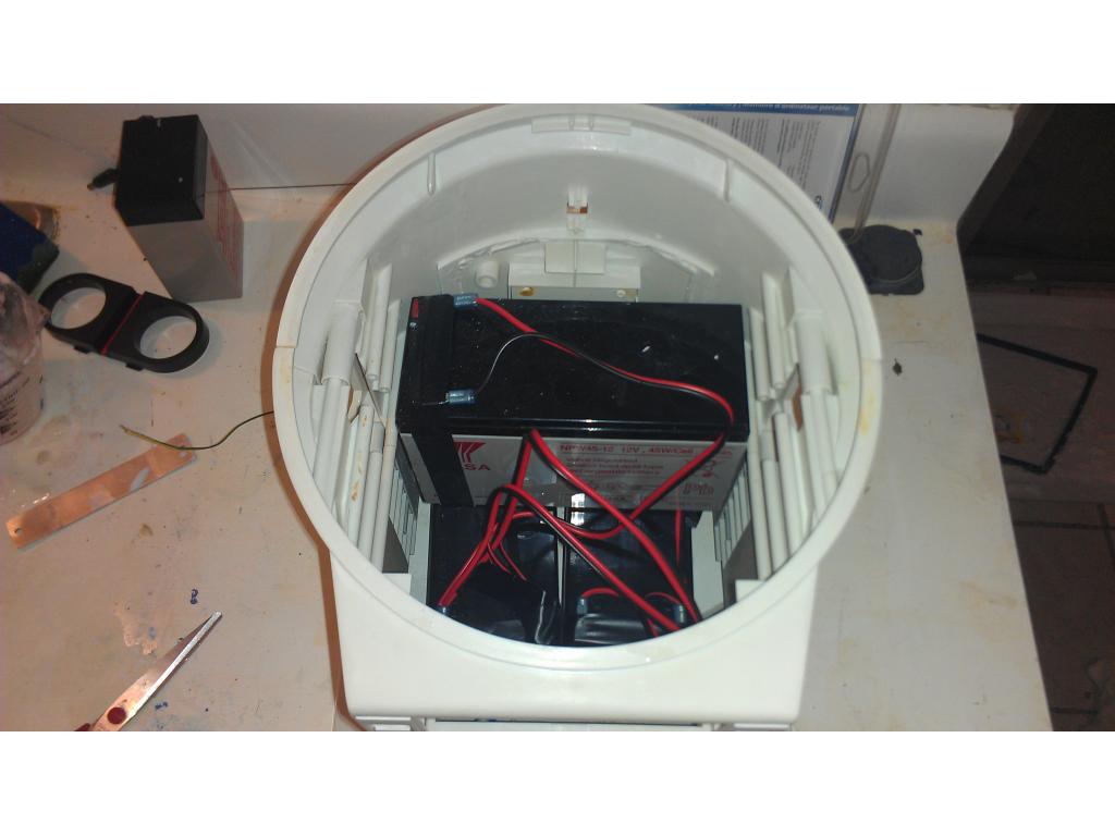
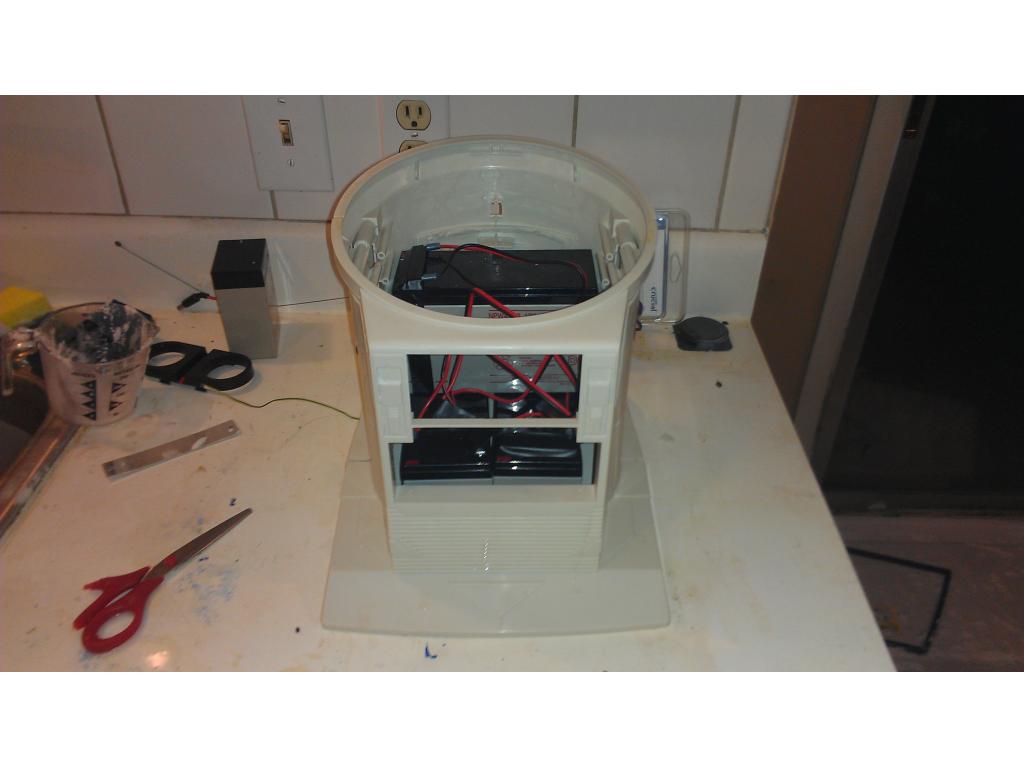
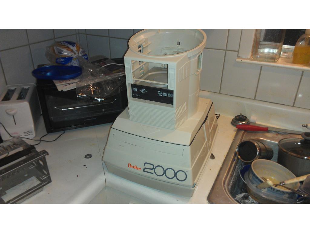
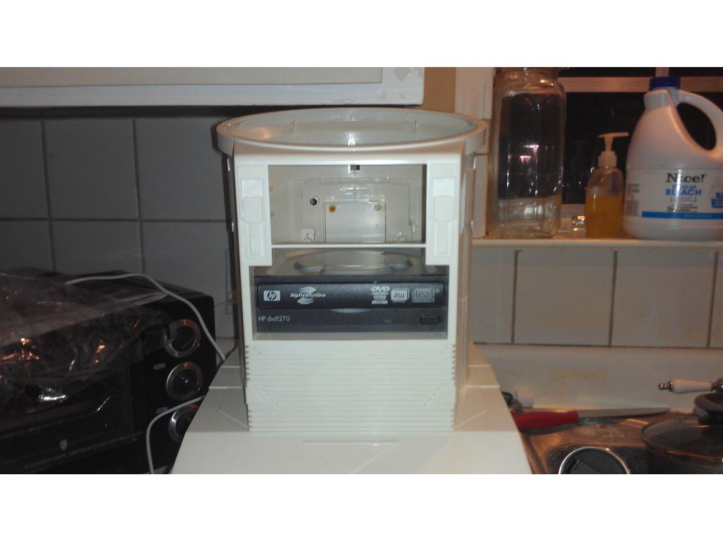
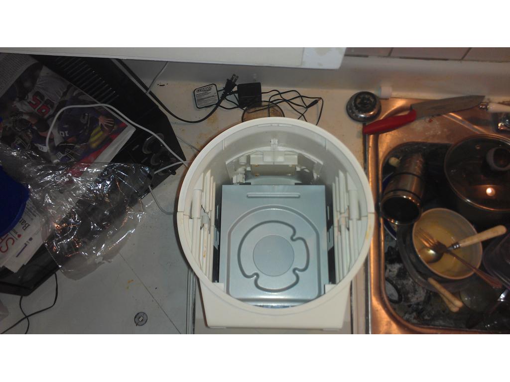
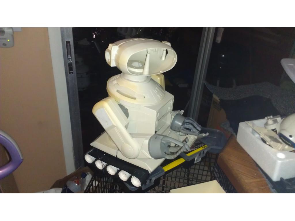
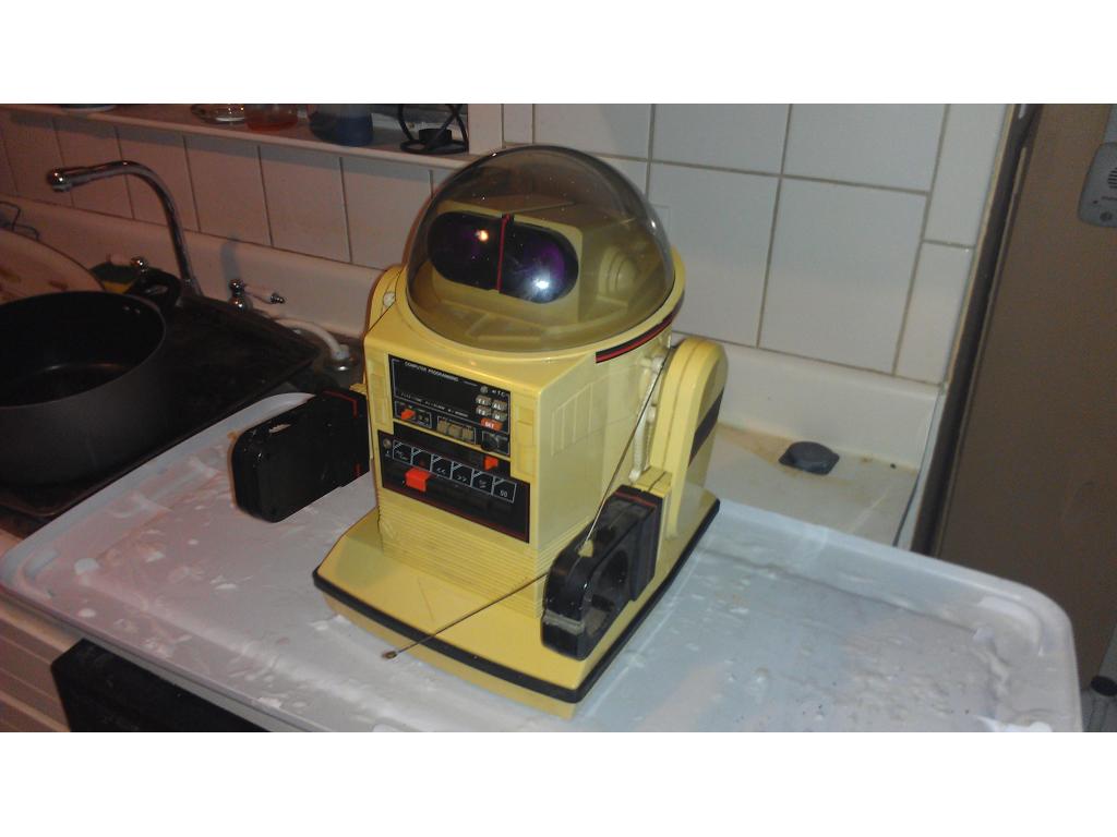
This project has evolved some , the basic rundown is I'm modding two Omnibots , one a regular the other a larger 2000 model. I will have two ezb kits , rad base idea was thrown out because of so much noise but could go back on the table if the omnibot drivetrain is too weak to pull it.

By jstarne1
— Last update
Discover more robots
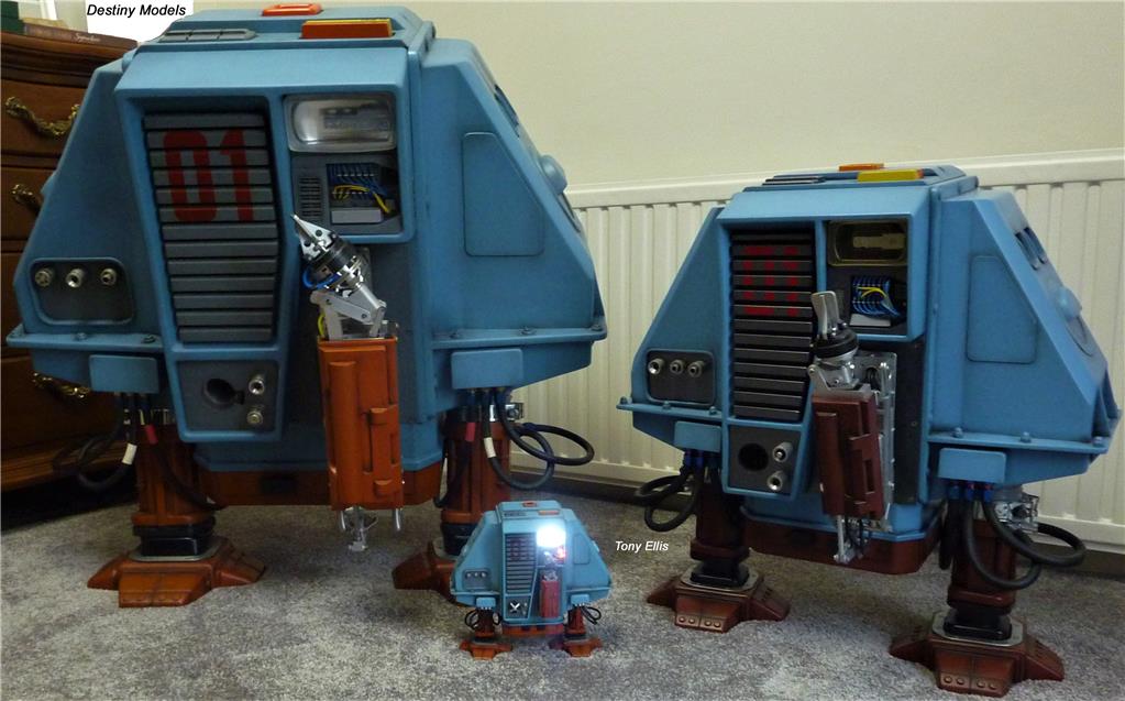
Toymaker's Dewey (Drone:1)
Iconic 1972 Silent Running drones on display: three scale models of Dewey showcased in my studio.

Jstarne1's Build A Giant 3D Printer , Live Build, Come Join...
Unboxing Folger FT-6 large-format 3D printer kit with 3-camera views; full build livestream planned to print larger,...

Ellis's Halloween Robot
Robot Max and helper Tele featured in a YouTube upload after earlier loading issues.

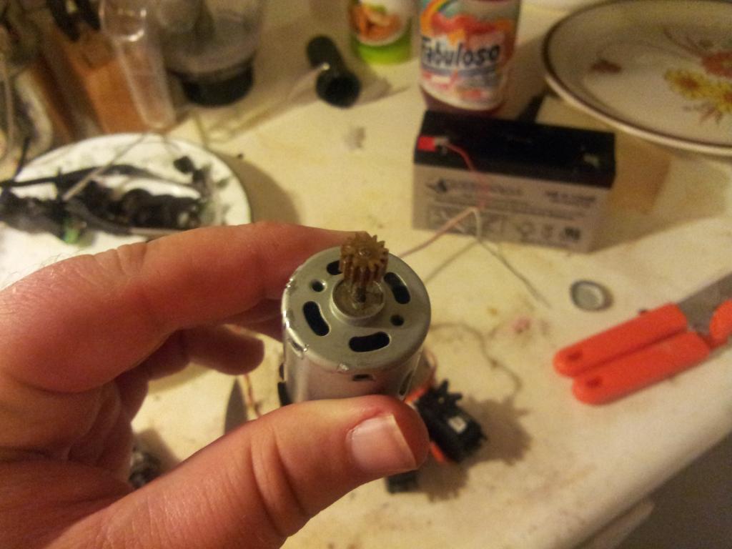
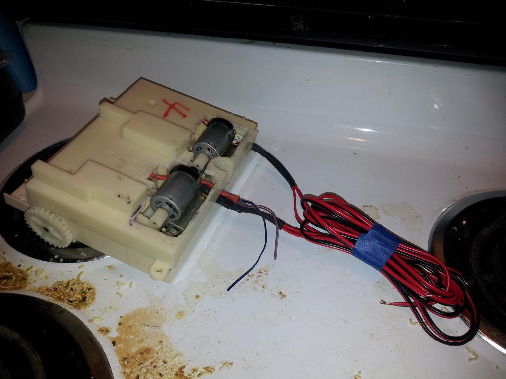
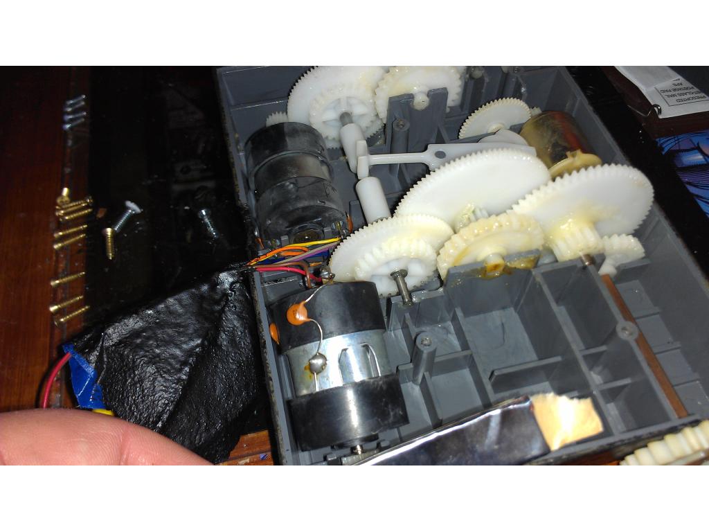
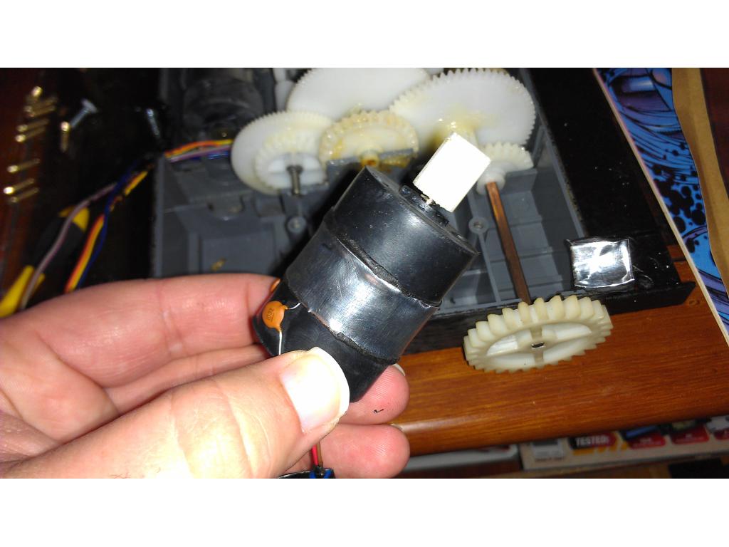
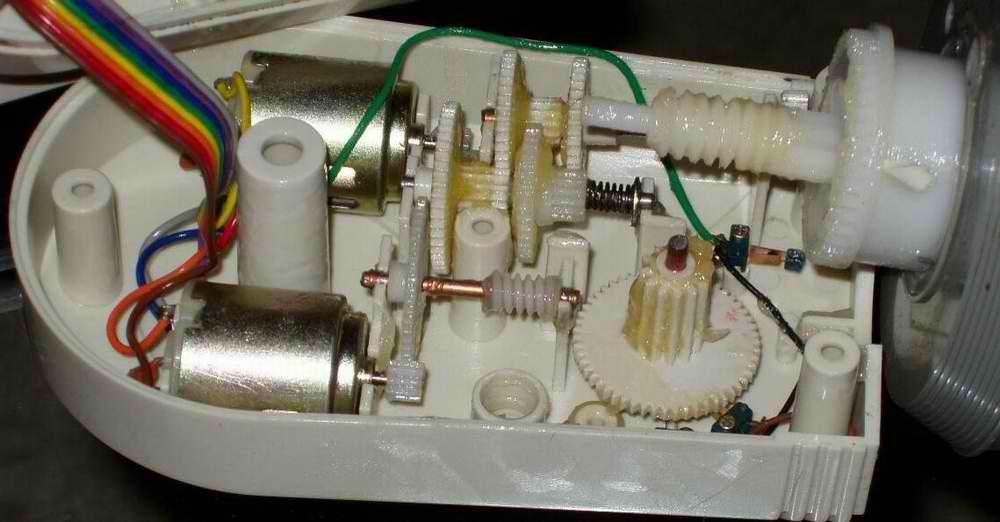
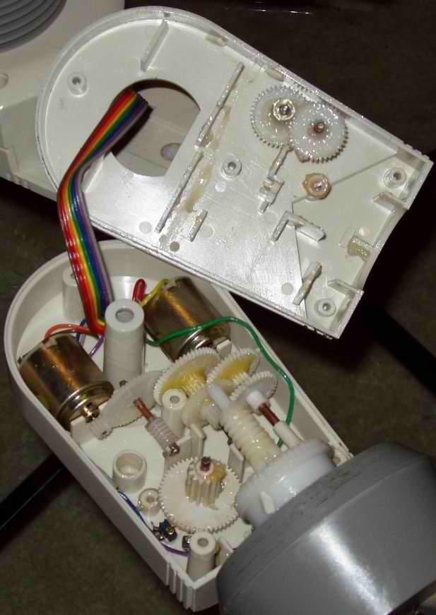
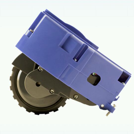
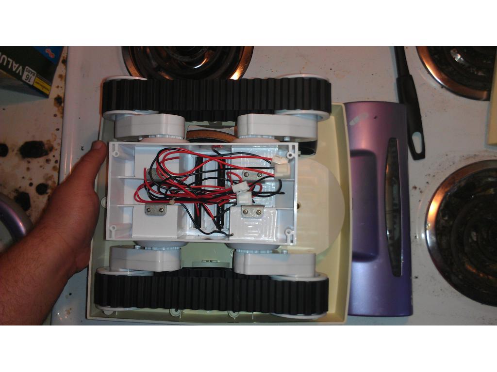
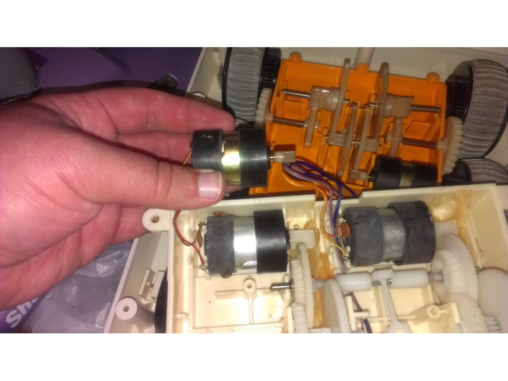
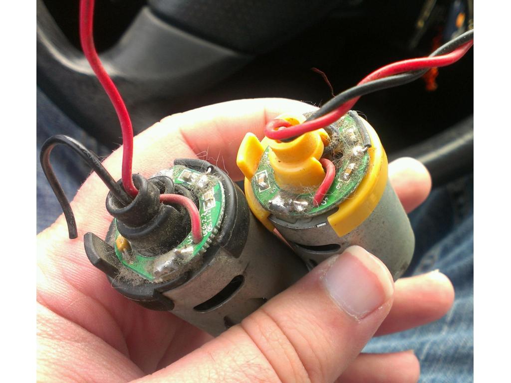
Current sensing , Dj post on current sensing..... My omnibot robot has been getting stuck the odd time. I had a conversation with the guys at Solarbotics and they suggested I through in a current sensing circuit. Wicked idea!
Current sensing is a method of monitoring the voltage through the DC motor. There are a few other methods of sensing a forced stall on a motor, including rotorary encoding with optical sensors. I am going to go with current sensing method.
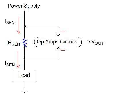
I found this document that was written by Microchip PIC. It is a good PDF file to read on the different methods. They even have diagrams explaining the circuit: PICMicro DC Motor Tips'n Tricks

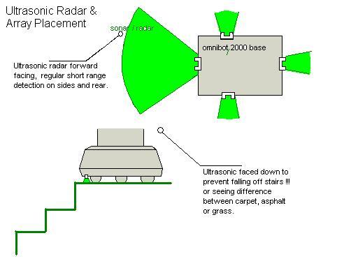
So the theory behind current sensing in the above diagram is quite simple. Now, technically with an ADC you should not need an OP AMP. If you don't know what an OP AMP is, it is a IC that compares two inputs (AND GATE). So 1 & 0 = 0, 0 & 1 = 0, 1 & 1 = 1, etcSo back to Current Sensing. Let's visualize the robot driving across your floor. You have magical distance sensors scanning back and forth returning distances... But we know that the robot can't see up or down, so you end up getting stuck on a coffee table or the leg of an office chair (my two big pet peeves). The robot stopping will put high load on the wheels, and DC Motor respectively.
The load can be detected by a change in voltage on the GND side of the motor.
What about an HBridge configuration? Glad you asked! Since the HBridge will change the polarity of the motor, you never know what side is GND. The solution? Add the current sensing to the Motor VSupply GND of the HBridge circuit.
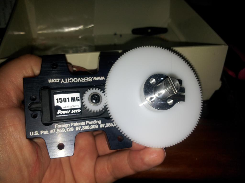
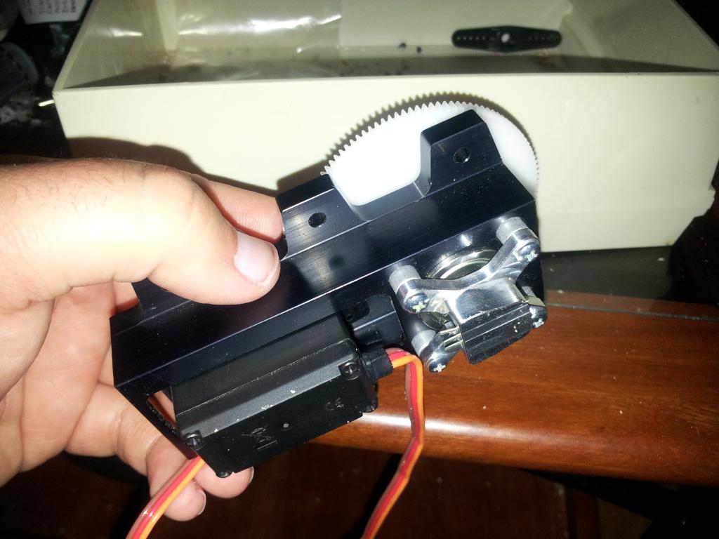
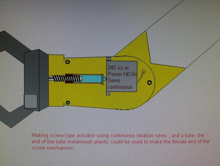
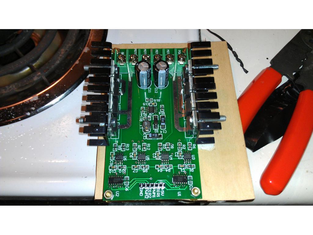
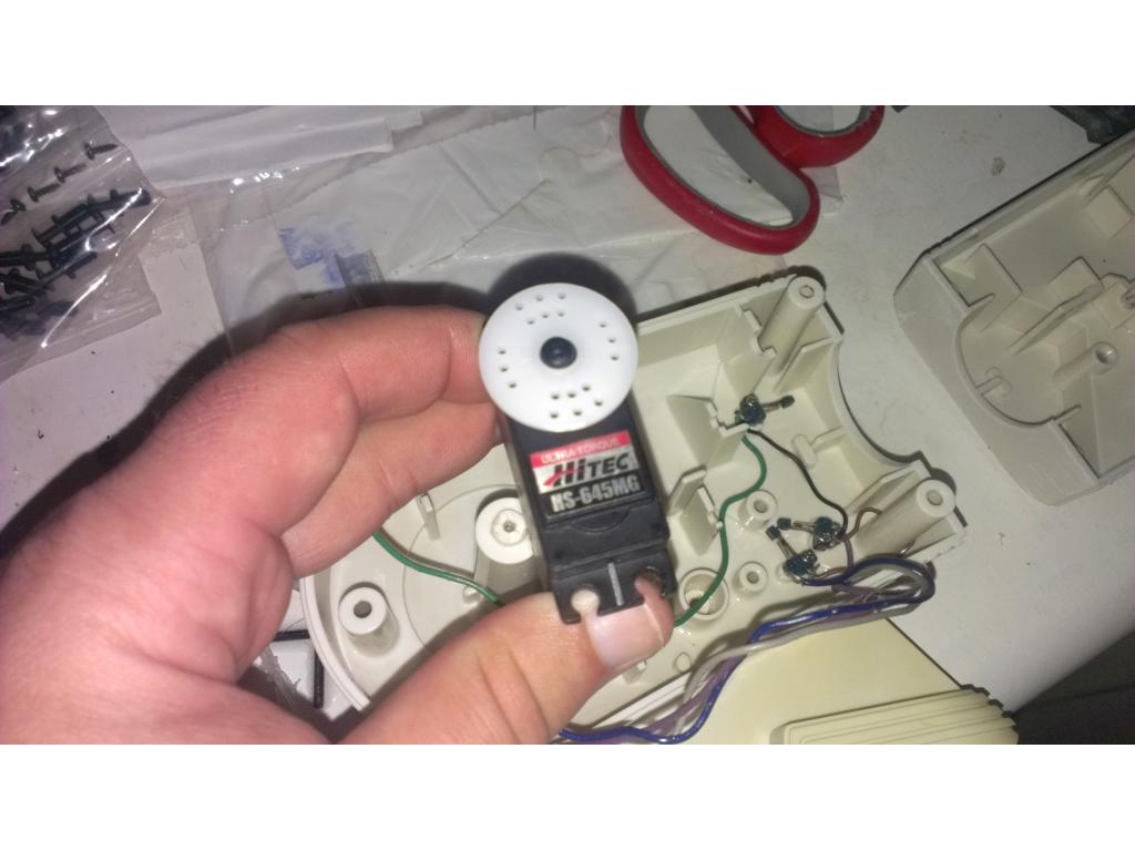
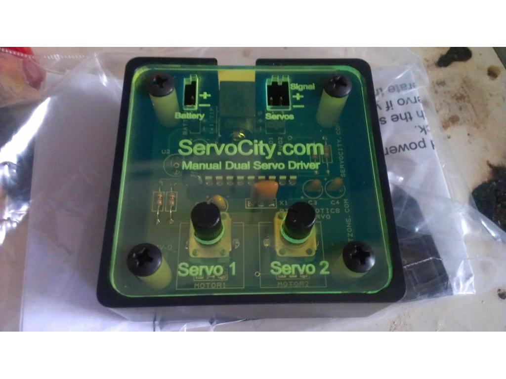
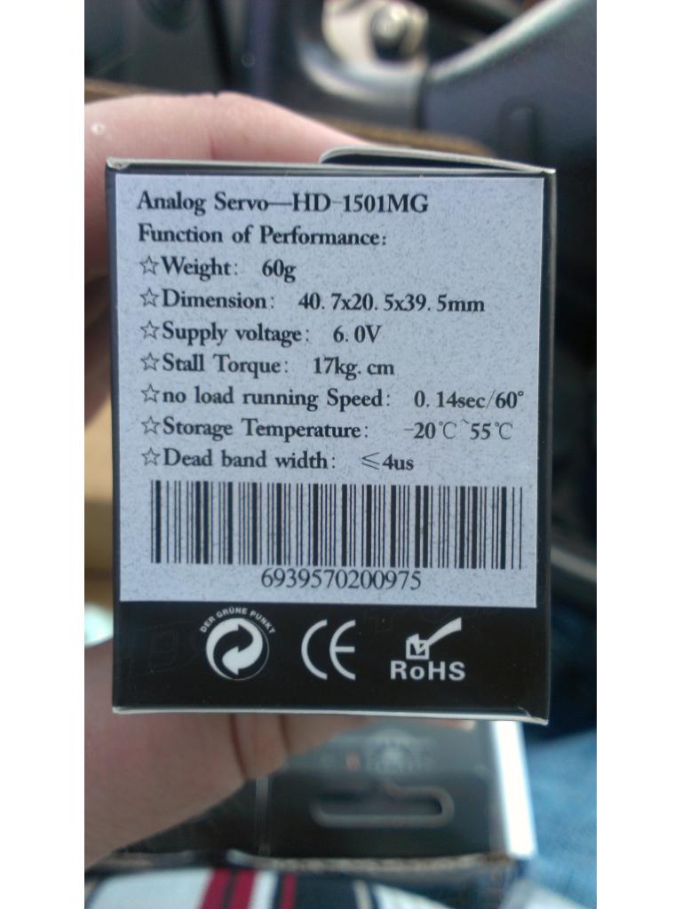
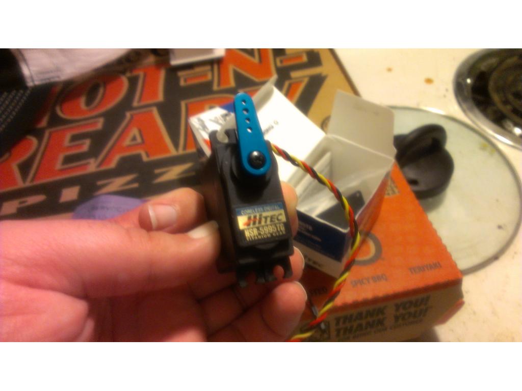
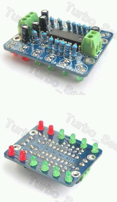
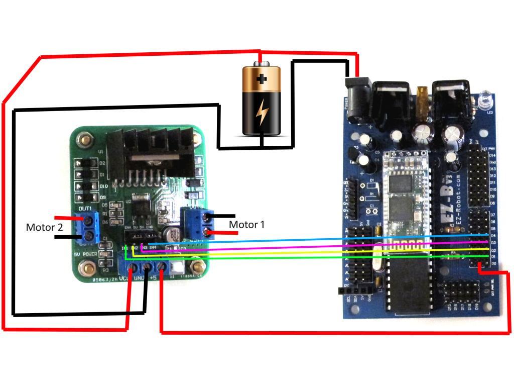
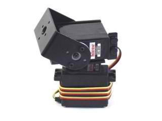
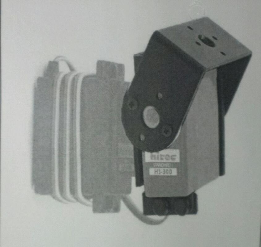
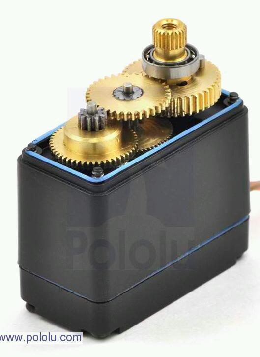
not on servo's circuit inside a servo doesnt have a shutdown circuit here is a circuit used for most servos
futaba s3003 servo cicuit has you can see no sense circuit here is a common H-BRIDGE circuit used for motors with a sense circuit
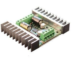
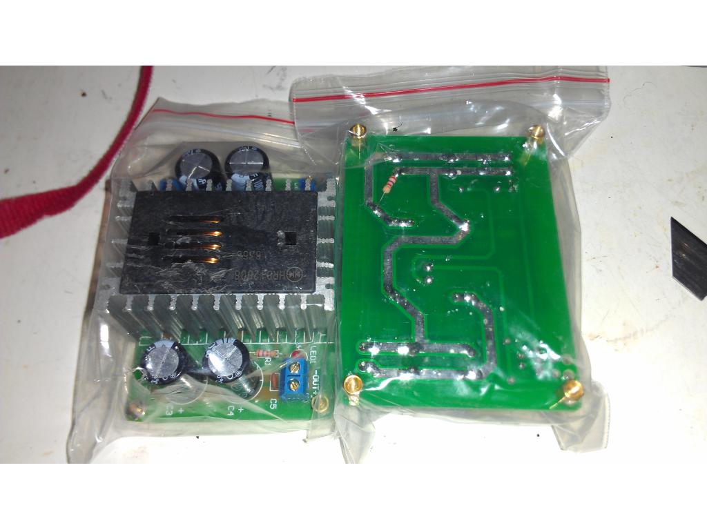
l298 h-bridge
has you can see it uses 2 sense resistors on gnd of the mosfet output stage it then produces a voltage output that feed into a comparator switch circuit on another chip or design you make and pull the brake low to shutdown the servo or motor how a comparator works its a amp that has a non inverted input and inverted input and when both are equal it switches ,depending on what input you use,other is variable voltage divider to adjust the current shutoff point
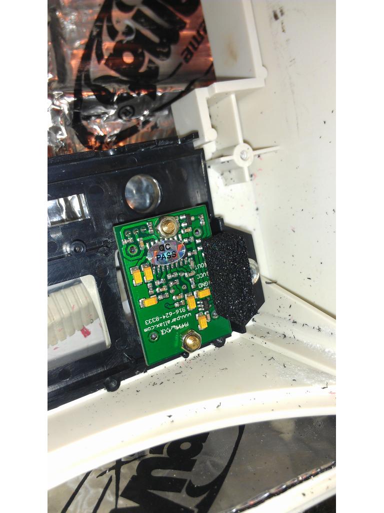
so only way to make a circuit for servo is use a current sense device,like a hall-effect current monitor or sense resistor and feed output to EZB analog input,or make a simple 1 chip comparator with a switch the servo power off
JOSH THAT CIRCUIT IS NOT THE BEST WAY TO DO IT because the sense circuit is not grounded and need a double supply double ended,if you look at every h-bridge chip or designs all use the ground of the motor for sensing current so only single ended supply is needed
So shouldn't I be able to connect to the servos ground just like you do with a h bridge and read current?
yes that is what i said was the best way circuit that DJ has up needs a special op circuit here is info from the same micro chip data sheet on using that type
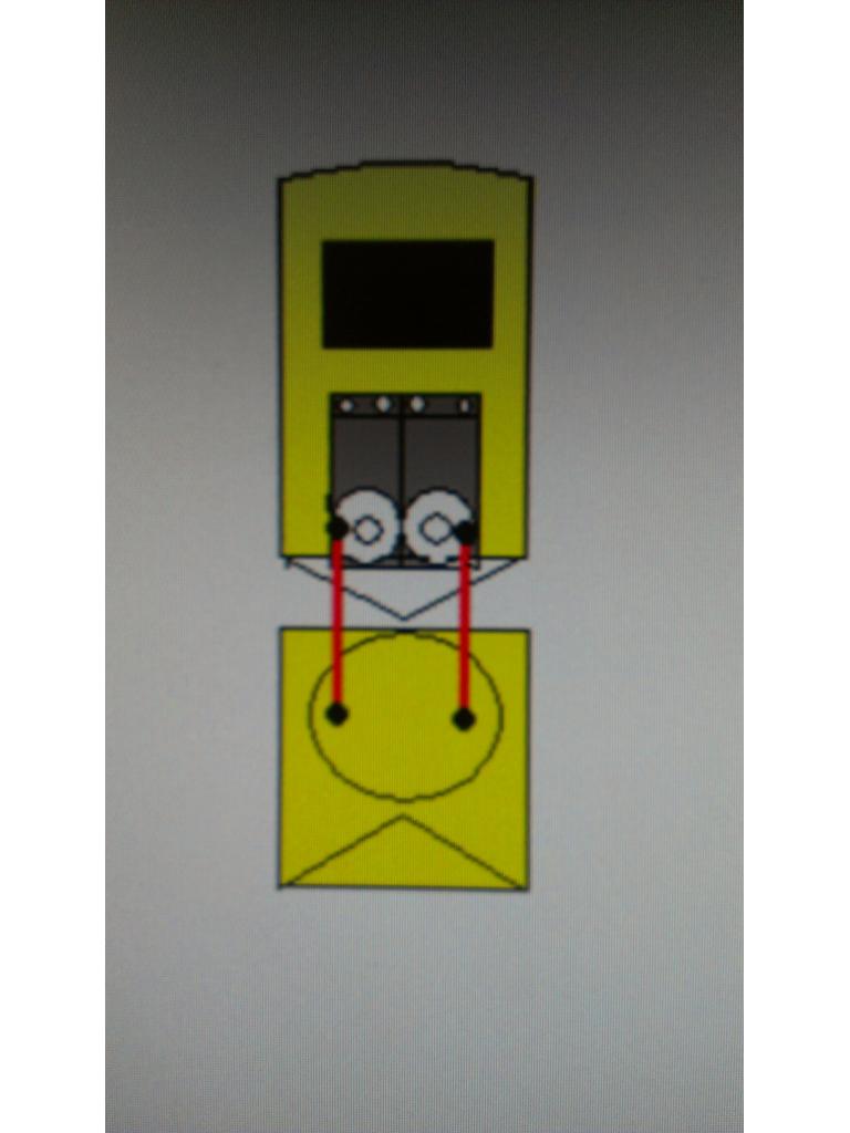
High side current sensing generally requires a differential amplifier with a common mode voltage range within the voltage of the supply.
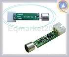
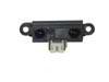
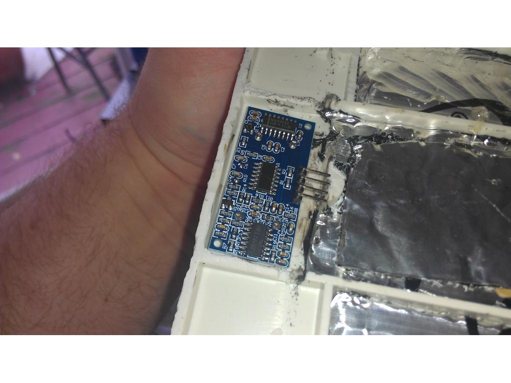
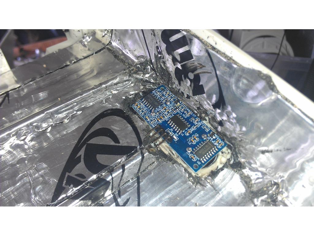
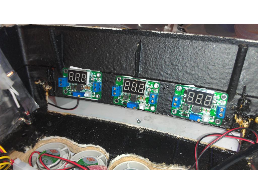
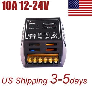
low side doesnt need it (gnd),ebay sells cheap current monitor boards about $6 and at different currents
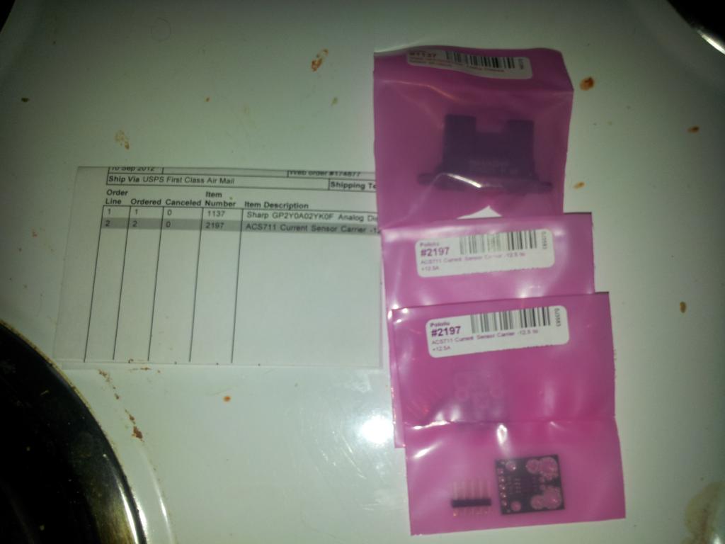
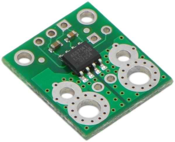
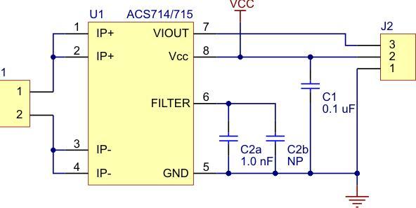
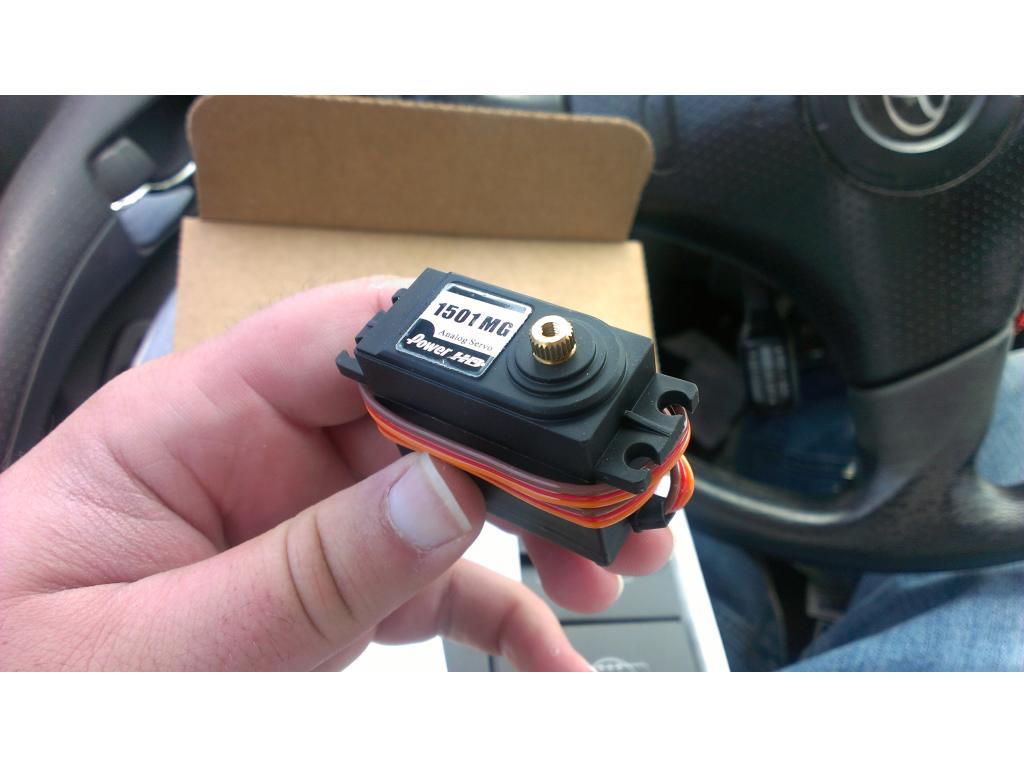
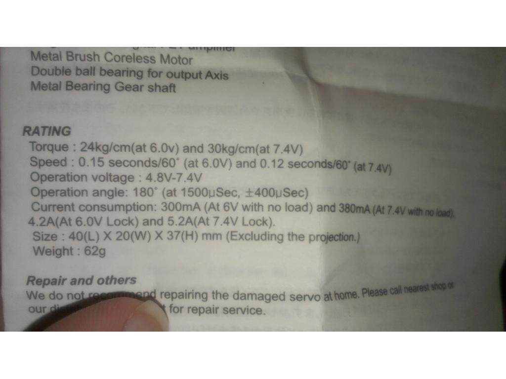
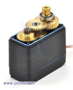
ACS712 is a very common 3 pin sensor,need to stay about double the stall current like if max current is 5 amps then a 10 amp current sensor is needed and dc output will be about 2.5 volts to feed into the analog input or comparator switch circuit besides ebay ,digikey has them too at different currents there is even a board made for it too,i think pololu sells them
pololu current sensor
they have others too,i bought a few while back,some 5 amps some 20 amps for my battery protection
Ok so this pollolu.com sensor will do what I need.
This would be what I needed for each claw and each drive motor in the base.right?
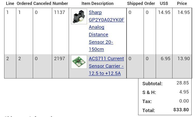
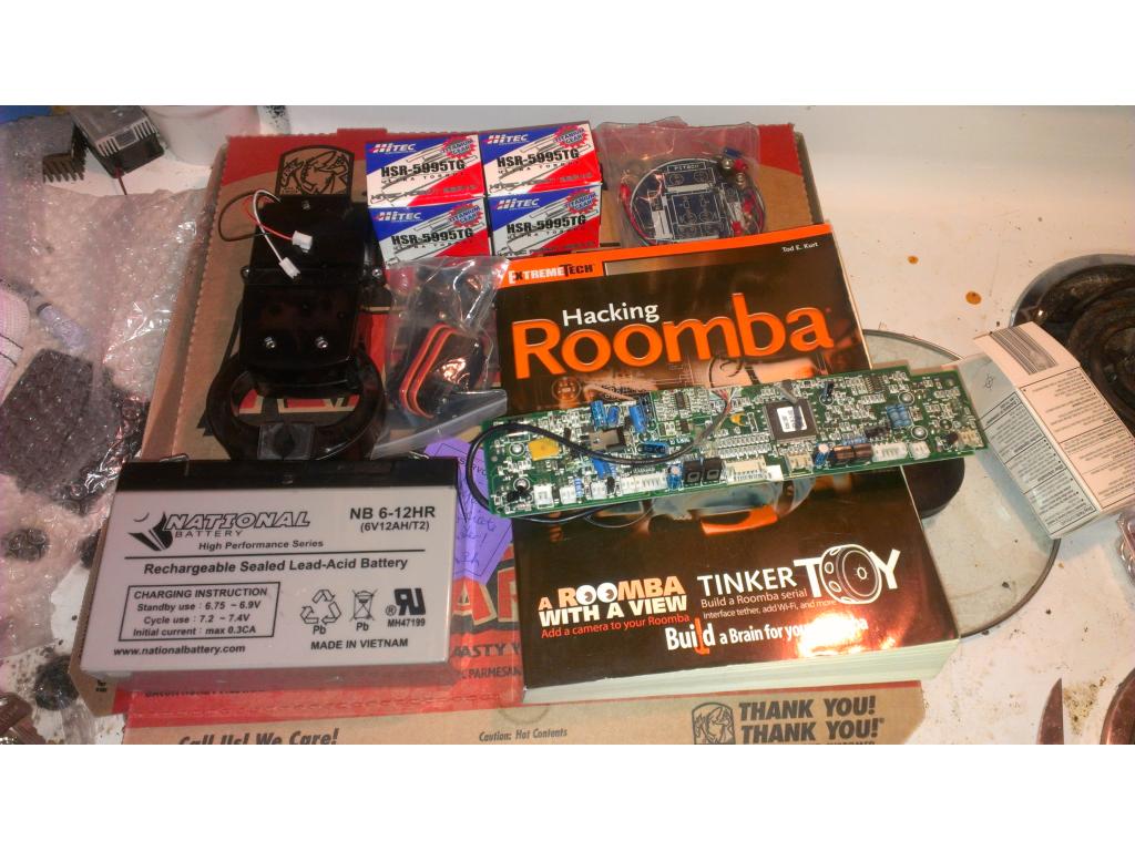
I have not received my last order from pollolu and I am already building another one lol.

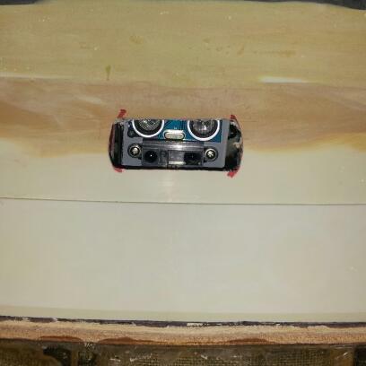
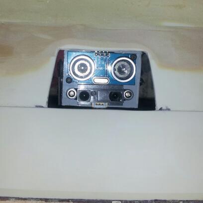
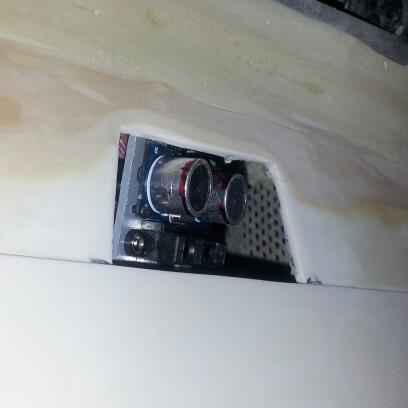
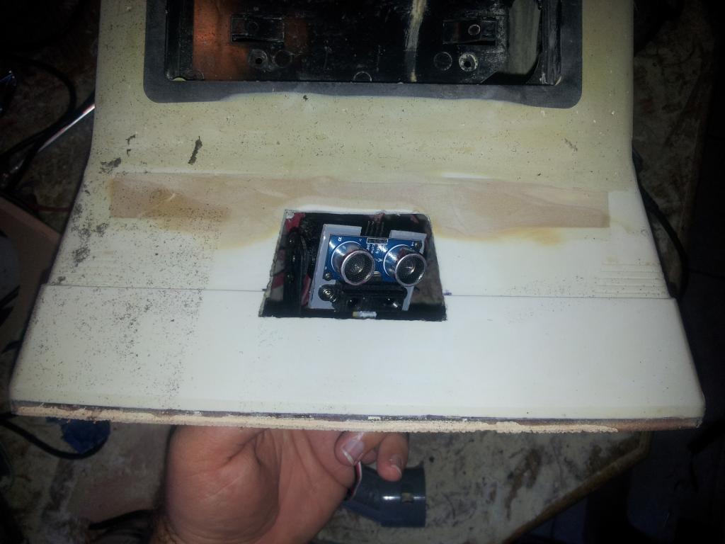
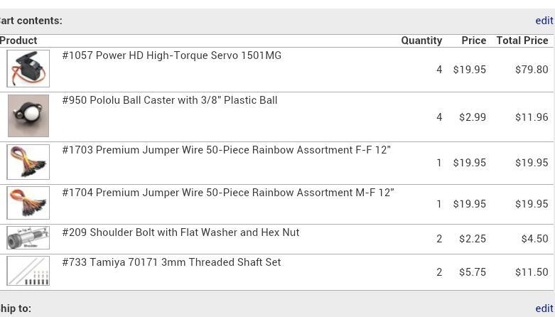
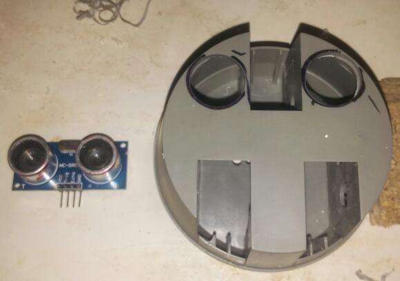
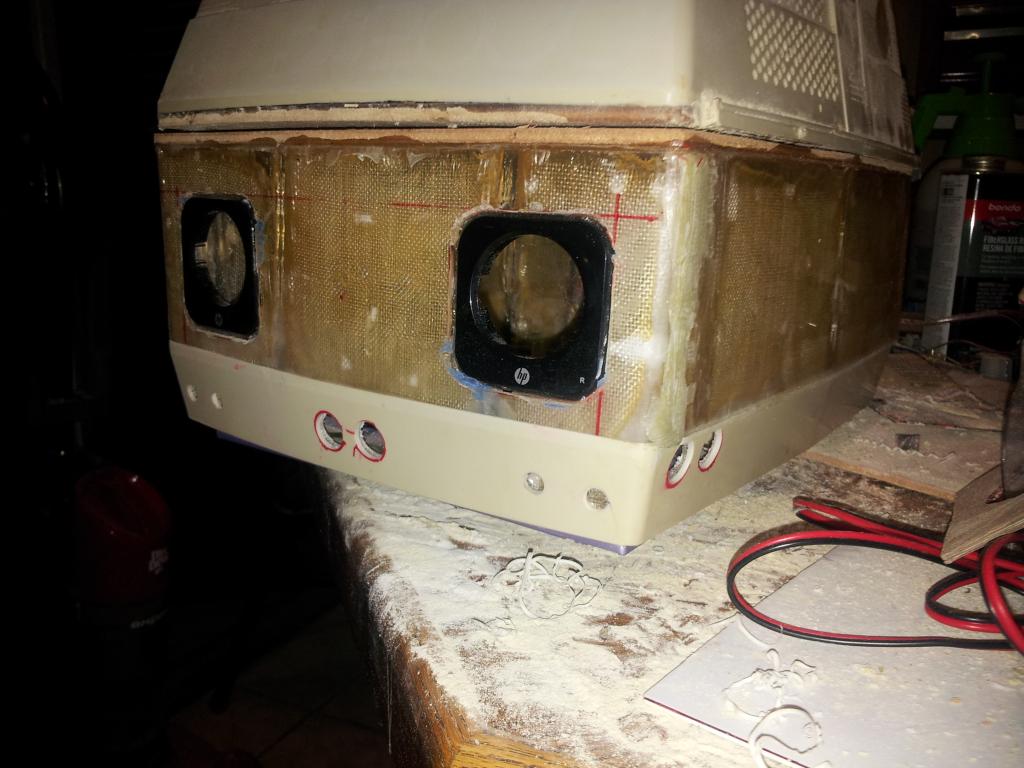
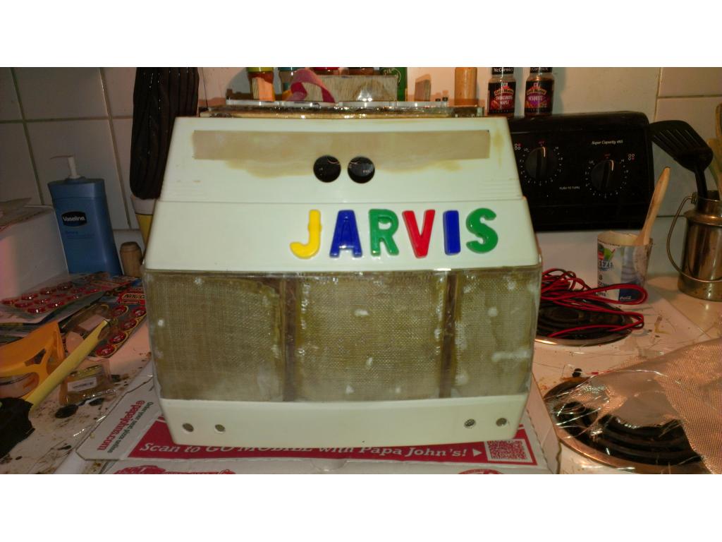
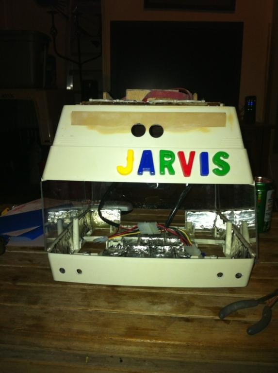
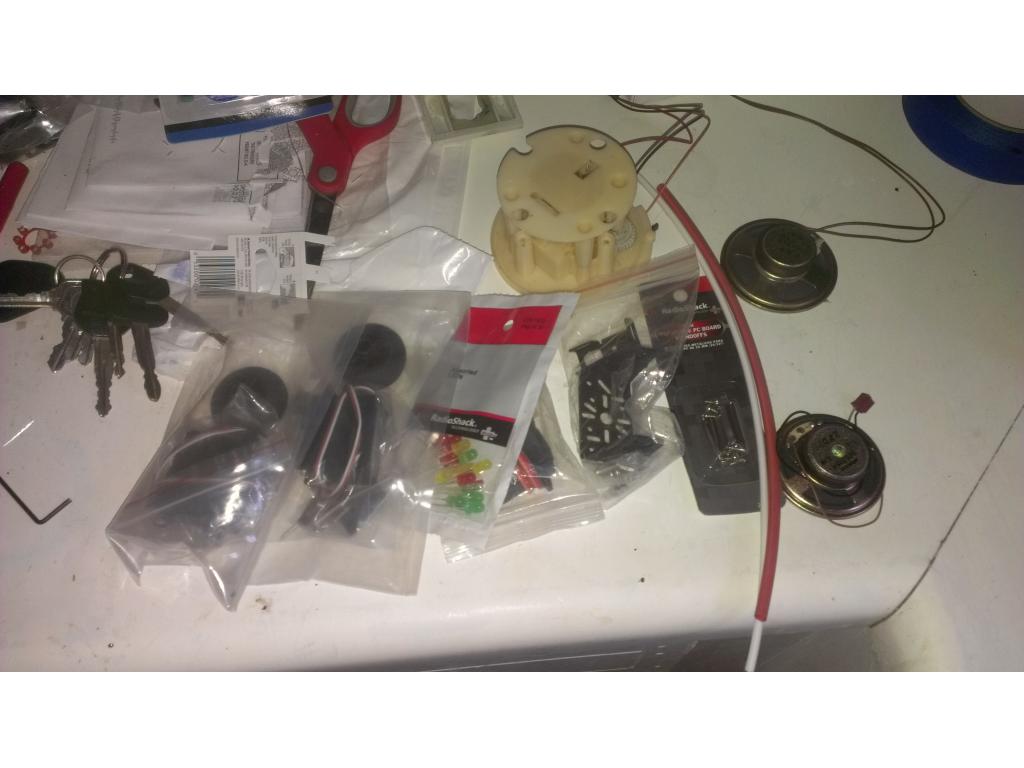
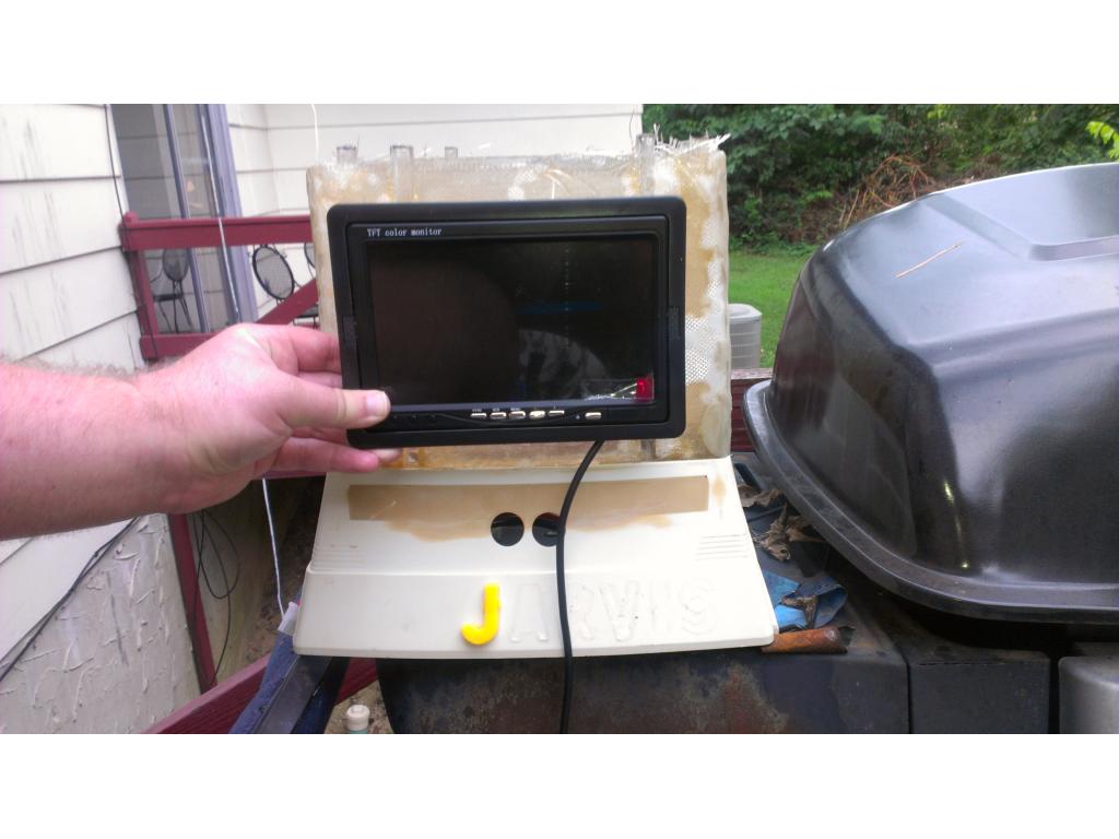
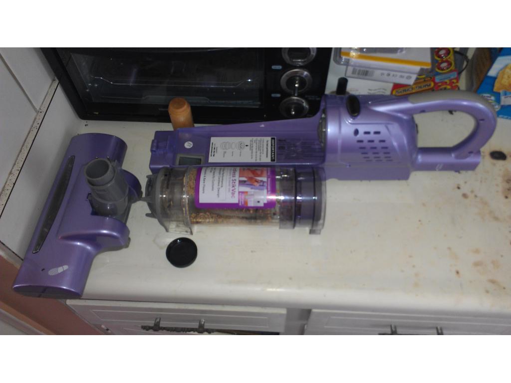
Here's my tentative next.pololu order. Force sensors for Jarvis fingers, has.sensors for.obvious reasons , 4 current.sensors.boards 2 for claws , 2 for drive.motors.A ezb has 8 add and 20 digital
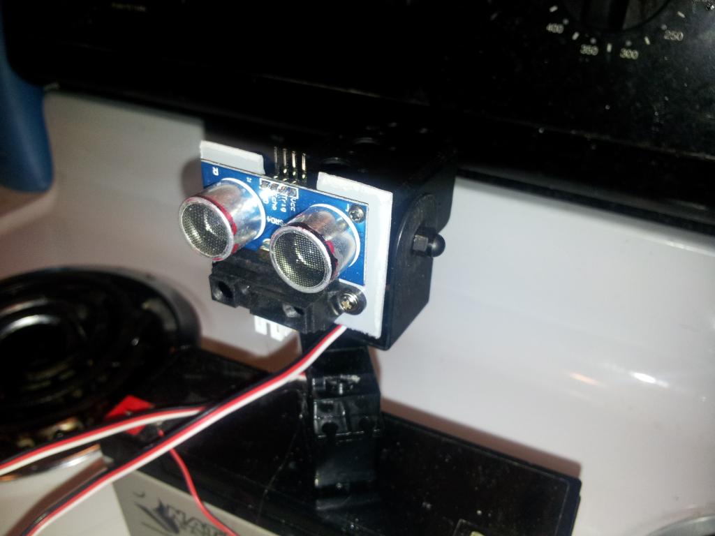
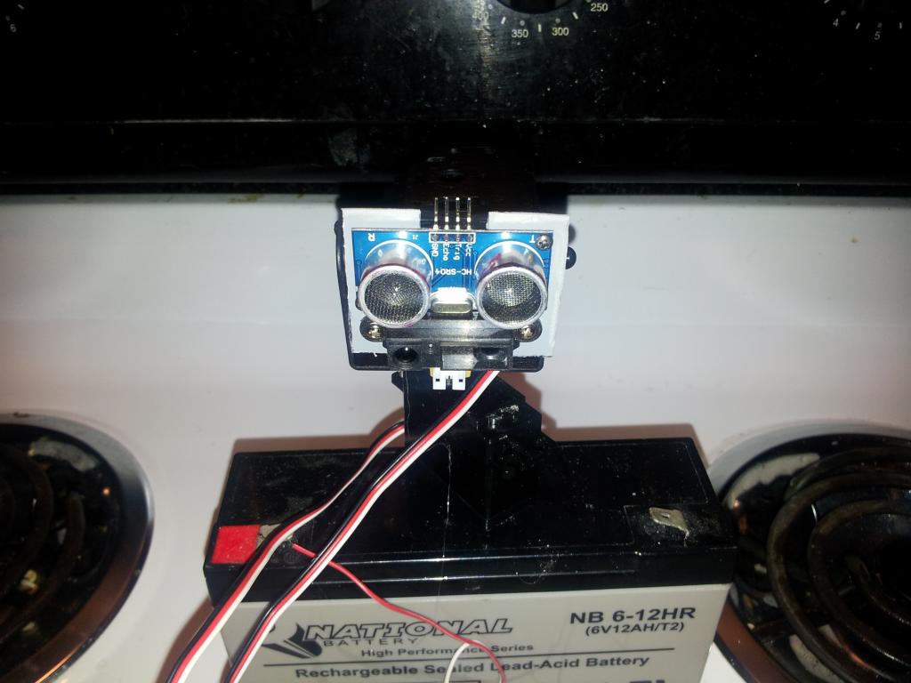
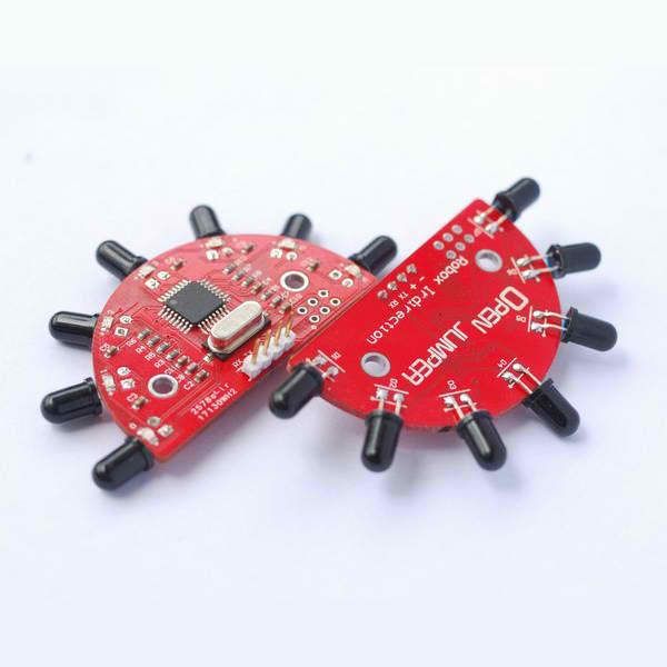
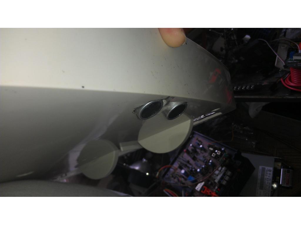
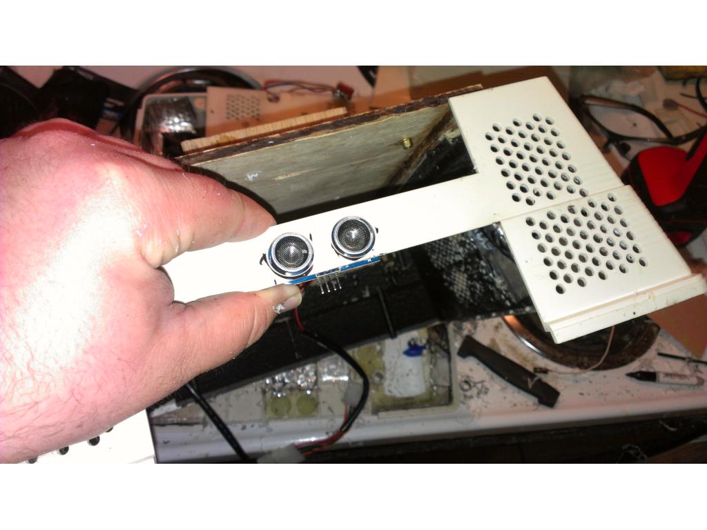
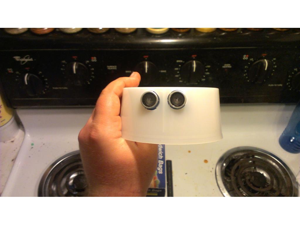
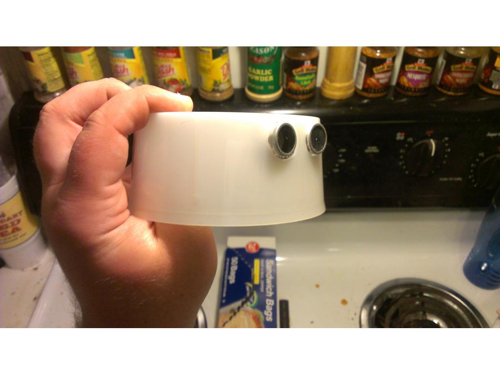
Digital 1.radar servo 2.sonar on radar servo 3. Sonar right side 4. Sonar left side 5. Sonar front /right 6. Sonar front/left 7.sonar rear 8.sonar face 9sonar top of head 10.sonar right inside of claw 11.sonar left inside of claw 12.motor right drive 13. Motor left drive 14. Vacuum trigger for power on 15. Current sense right side drive 16.current sense left side drive 17.right claw current sense 18.left claw current sense 19.IR directional sensor 20.