


-634700966886250000.jpg)
-634700967015000000.jpg)
-634700967157968750.jpg)
-634702814800312500.jpg)
-634702600865468750.jpg)
-634702601116718750.jpg)
-634702602252031250.jpg)
-634702602665625000.jpg)
-634702602851875000.jpg)
-634694134410000000.jpg)
-634693960892812500.jpg)
-634693961752343750.jpg)
-634693953179375000.jpg)
-634693953336093750.jpg)
-634693164809062500.jpg)
-634693165327500000.jpg)
-634693165925625000.jpg)
-634693166147343750.jpg)
-634786542943876953.jpg)
-634796120303593750.jpg)
-634796120470312500.jpg)
-634812479455986328.jpg)
-634812479726035156.jpg)
-634812480620283203.jpg)
-634812481334052734.jpg)
-634812482341699218.jpg)
-634822681001005859.jpg)
-634822681580644531.jpg)
-634822681777470703.jpg)
-634821106166250000.jpg)
-634821106572812500.jpg)
-634821106815625000.jpg)

-634814909605058593.jpg)
-634814909850224609.jpg)
-634814910193212890.jpg)
-634814910596445312.jpg)
-634820188048437500.jpg)
-634820188647187500.jpg)
-634820189032656250.jpg)
-634718079154687500.jpg)
-634718080622031250.jpg)
-634714909191250000.jpg)
-634714909644843750.jpg)
-634713078392031250.jpg)
-634713078781250000.jpg)
-634720009877968750.jpg)
-634749341545937500.jpg)
-634749341951406250.jpg)
-634732946203437500.jpg)
-634708797562402343.jpg)
-634706000248750000.jpg)
-634705927185312500.jpg)
-634705927626406250.jpg)
-634705928146250000.jpg)
-634705929045781250.jpg)
-634705929717812500.jpg)
-634705930336093750.jpg)
-634705930540468750.jpg)
-634705931037812500.jpg)
-634709695807265625.jpg)
-634709696076181640.jpg)
-634711364771718750.jpg)
-634711364485781250.jpg)
-634712172318906250.jpg)
-634771897291406250.jpg)
-634771897466093750.jpg)
-634771897849687500.jpg)
-634771898236093750.jpg)
-634771898712187500.jpg)
-634771899102656250.jpg)
-634771899822656250.jpg)
-634771900771562500.jpg)
-634771901301875000.jpg)
-634768466924746093.jpg)
-634768467383681640.jpg)
-634772580489218750.jpg)
-634772581075781250.jpg)
-634772581532343750.jpg)
-634772581721718750.jpg)
-634773400815625000.jpg)
-634773401032187500.jpg)
-634781365777988281.jpg)
-634781366040302734.jpg)
-634781366299042968.jpg)
-634766553798554687.jpg)
-634766556025839843.jpg)
-634759732245312500.jpg)
-634765021896093750.jpg)
-634765022115000000.jpg)
-634765022326562500.jpg)
-634765023386093750.jpg)
-634765855550937500.jpg)
-634765856533437500.jpg)
-634765856756250000.jpg)
-634845177217089843.jpg)
-634845177425585937.jpg)
-634857207521406250.jpg)
-634857208212500000.jpg)
-634857208786718750.jpg)
-634826982093593750.jpg)
-634838602835000000.jpg)
-634838603089687500.jpg)
-634838603585312500.jpg)
-634871181815468750.jpg)
-634871183099531250.jpg)
-634871128238750000.jpg)
-634870976497031250.jpg)
-634870976894687500.jpg)
-634880528374375000.jpg)
-634880528707656250.jpg)
-634880529073593750.jpg)
-634892824736386719.jpg)
-634892824903066406.jpg)
-634892825090117187.jpg)
-634892825255283203.jpg)
-634880812756406250.jpg)
-634870194470625000.jpg)
-634870194829687500.jpg)
-634865232676250000.jpg)
-634863402043750000.jpg)
-634863402351562500.jpg)
-634863402584218750.jpg)
-634863404238125000.jpg)
-634869405242656250.jpg)
-634869405424687500.jpg)
-634869405586562500.jpg)
-634869405943906250.jpg)
-634869406072656250.jpg)
-634869404353281250.jpg)
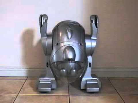
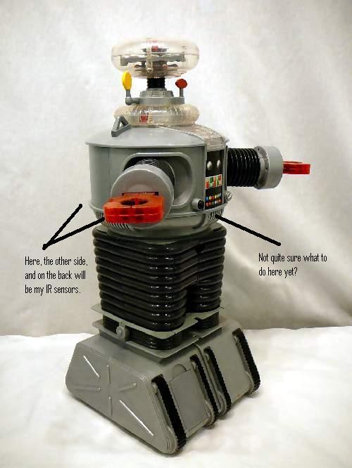
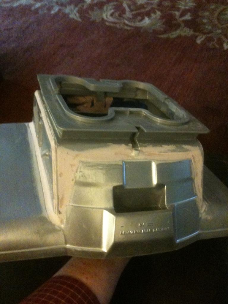
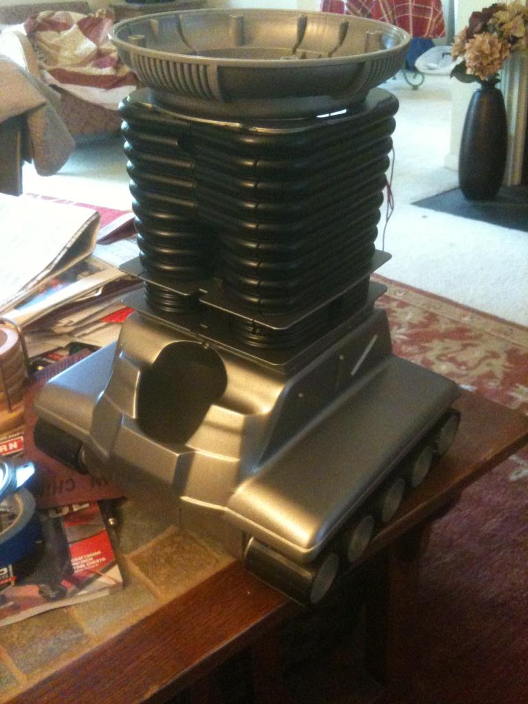
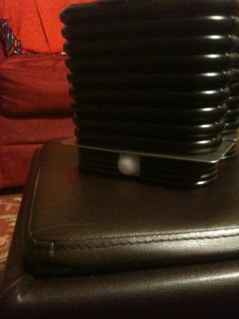
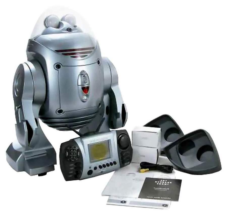
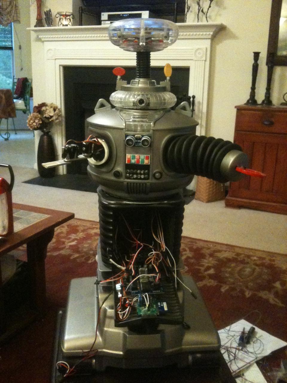
Now that I have finished B.O.B., my get your feet wet bot, I have begun my next hack. This next robot will bridge the gap between Bob and my ultimate big robot. I am starting with a remote controlled B9 toy from Trendmasters. It was very limited in what it did, and the drive section was pathetic, but it was B9!
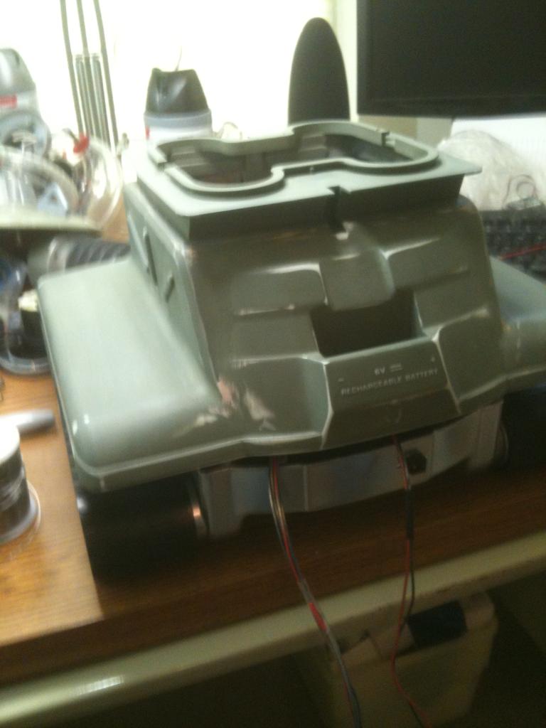
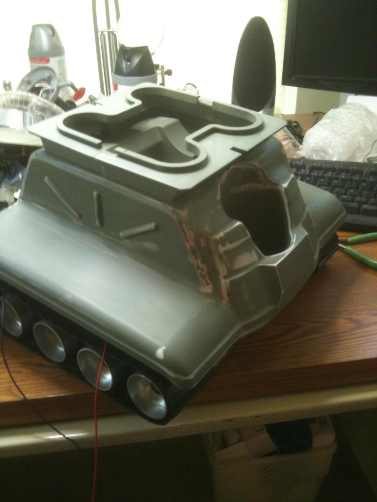
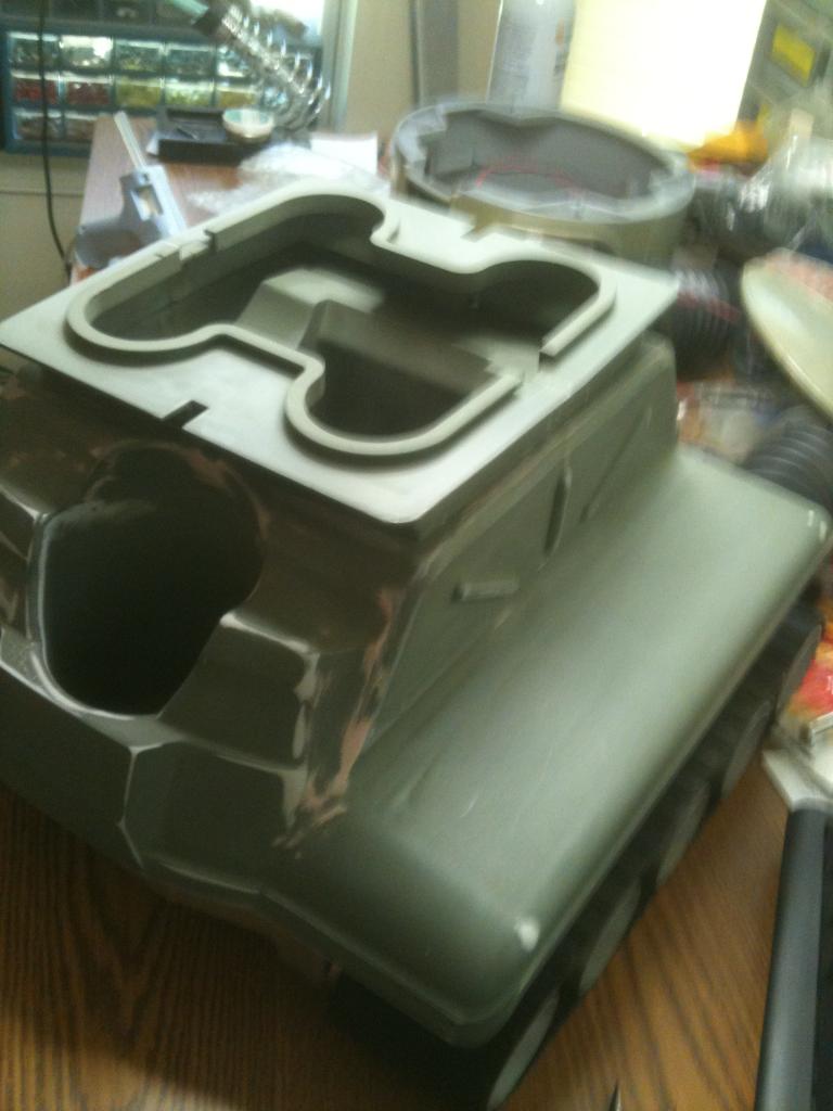
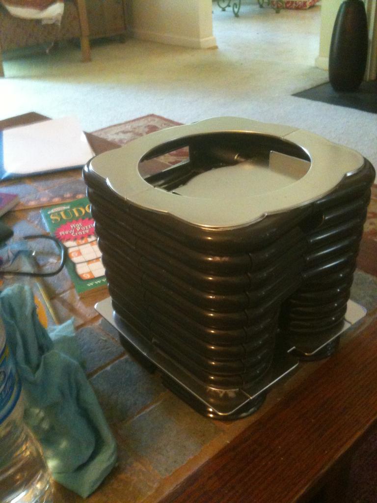
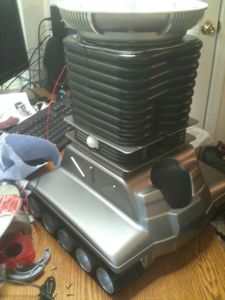
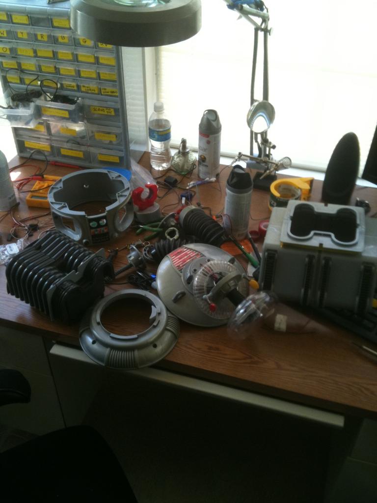
Before Pics:
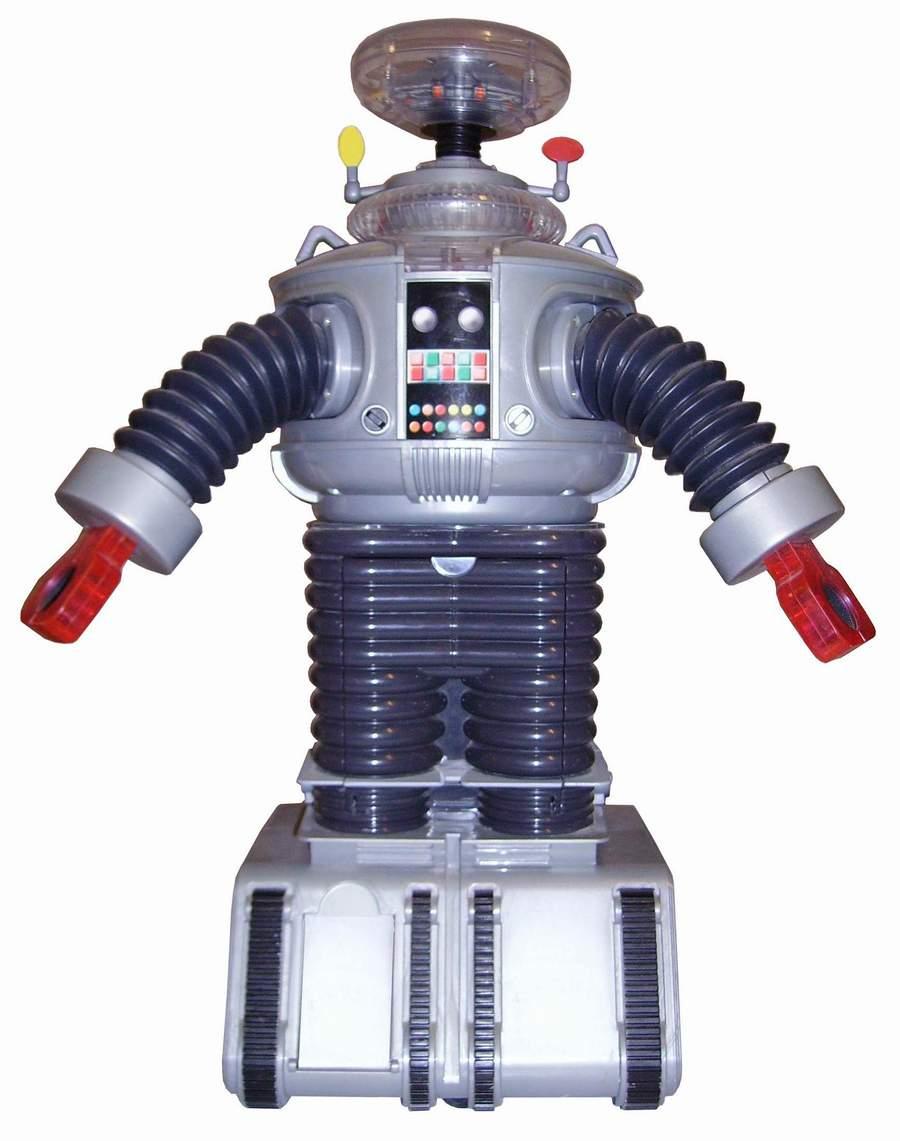
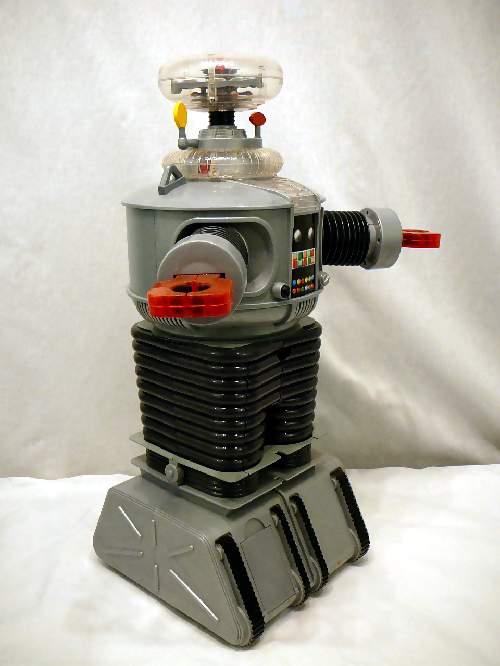

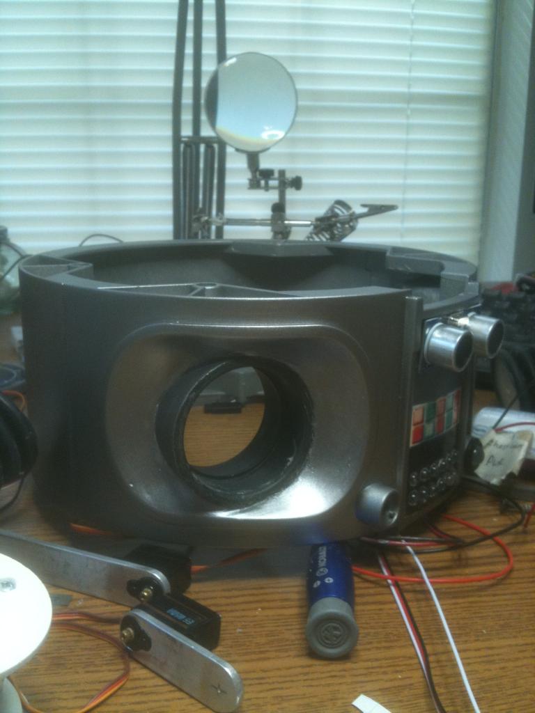
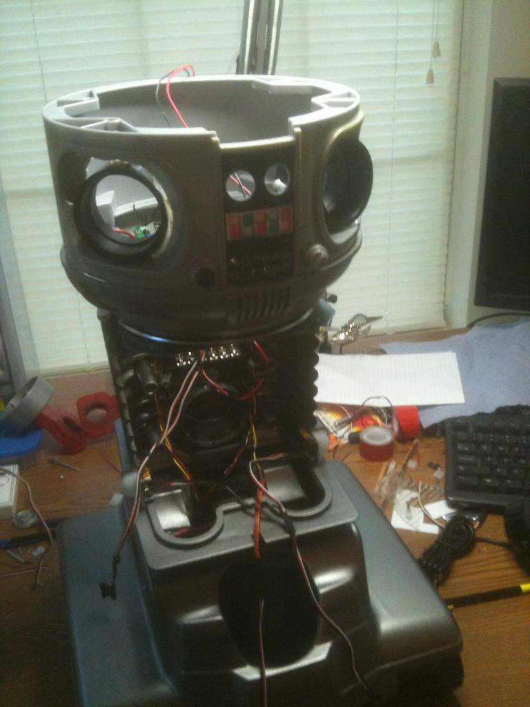
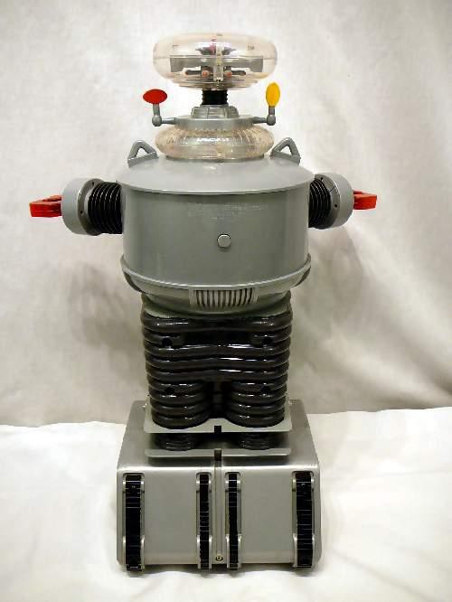
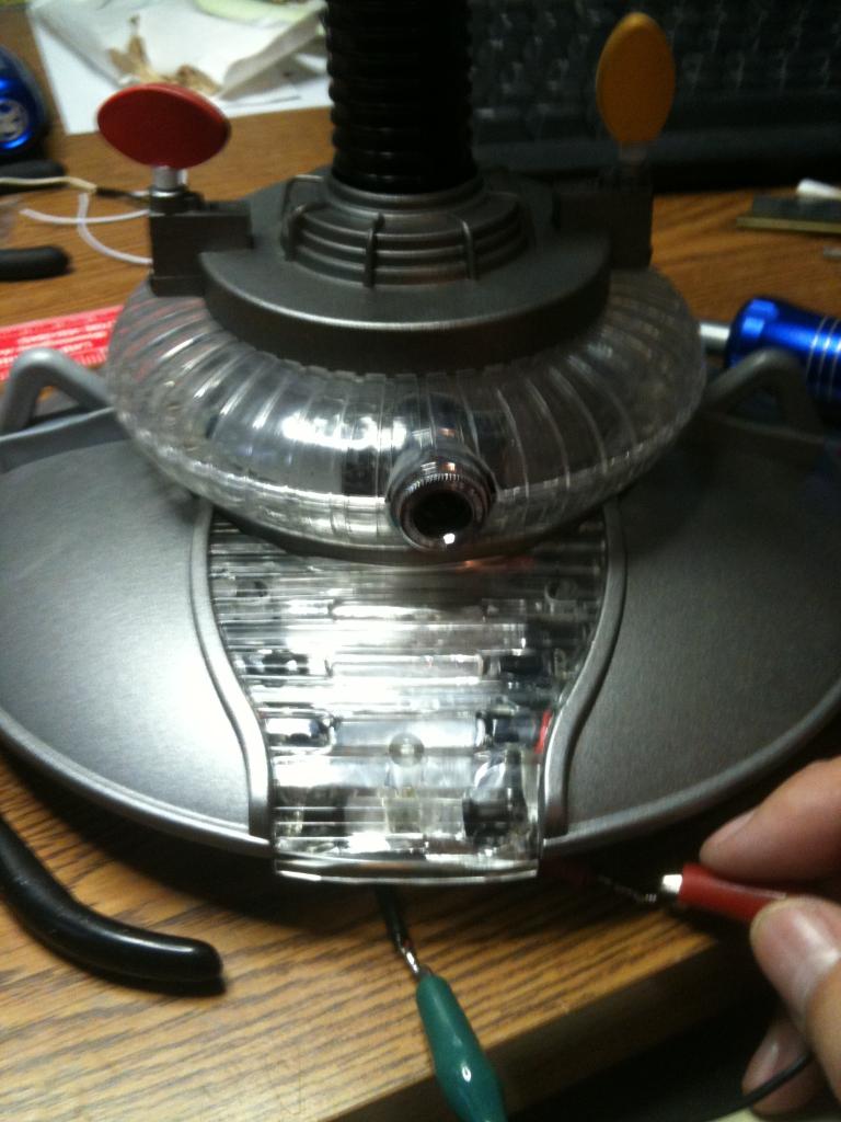
Here is what B9 looks like now:
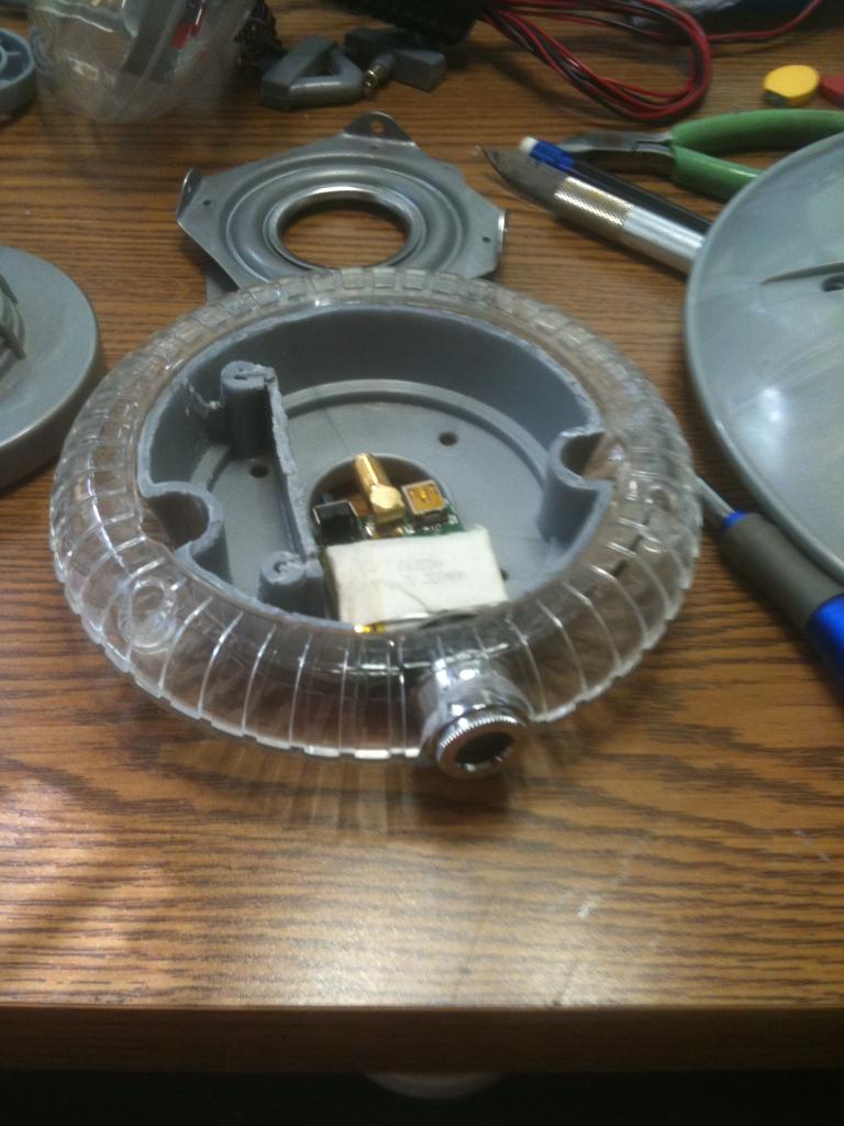
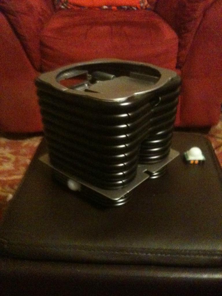
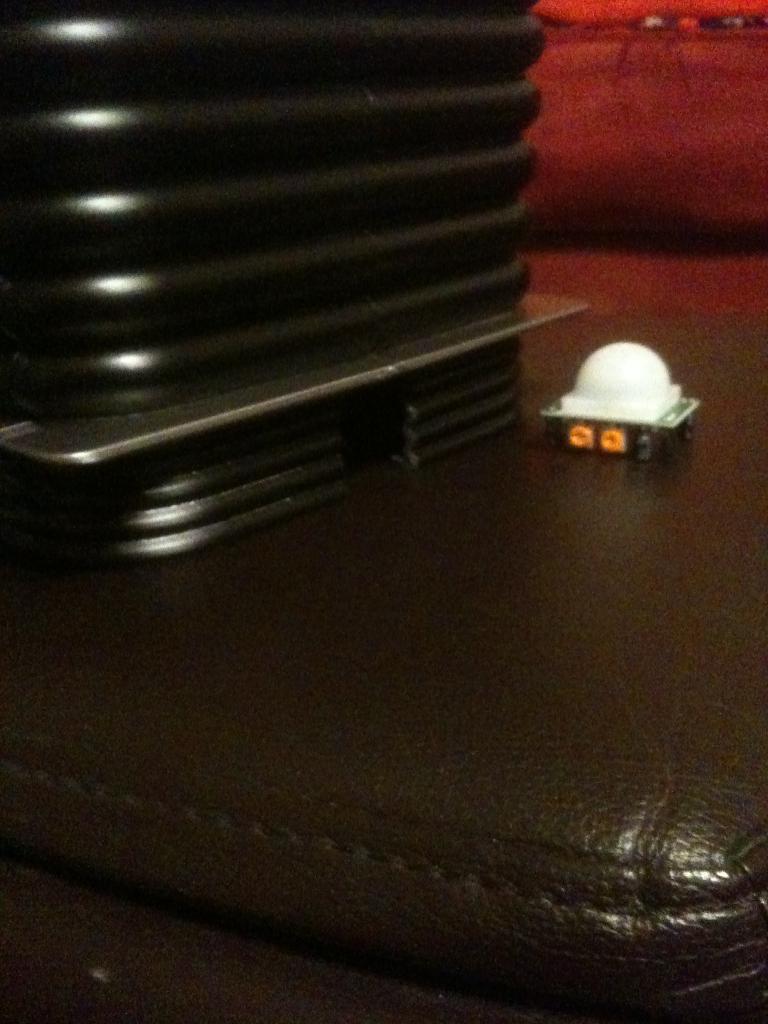
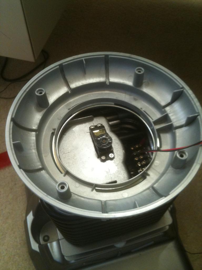
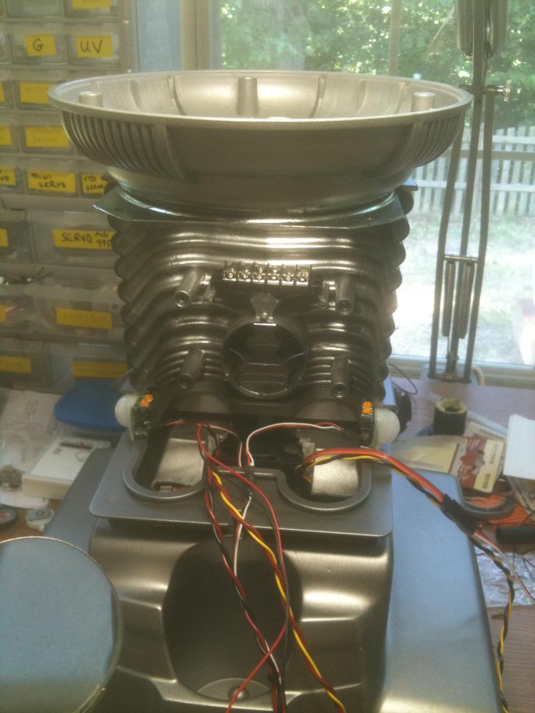
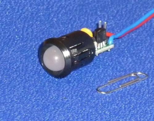
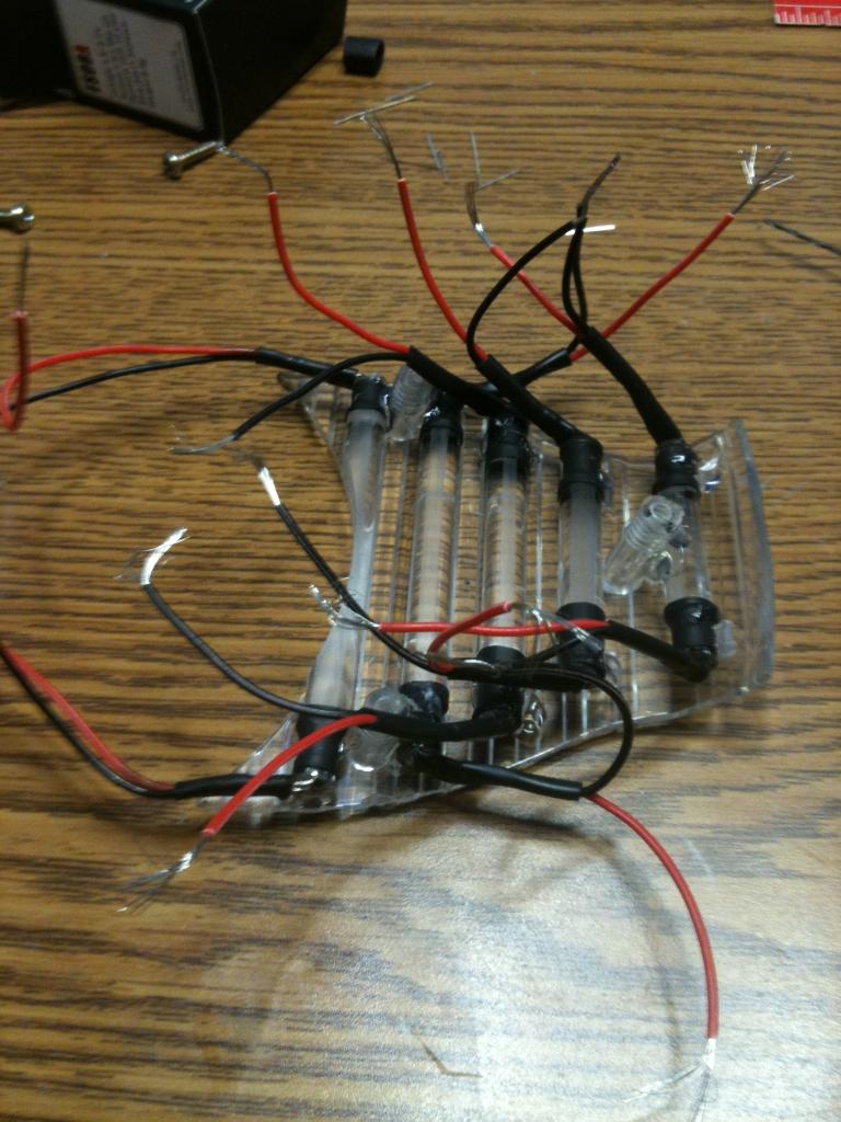
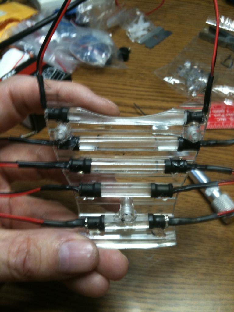
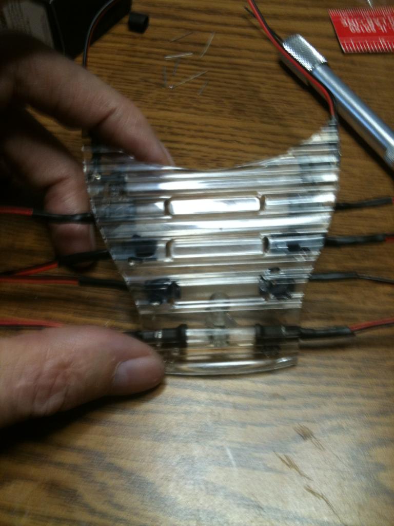
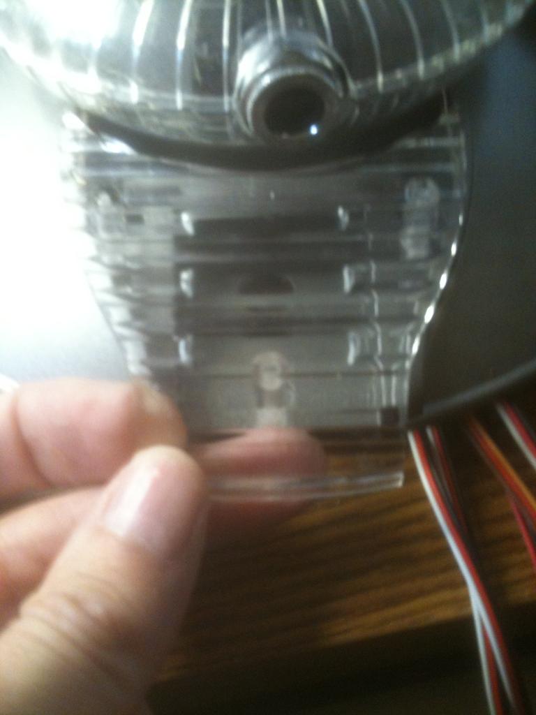
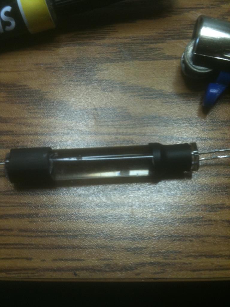
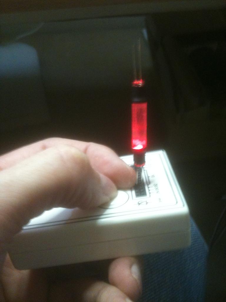
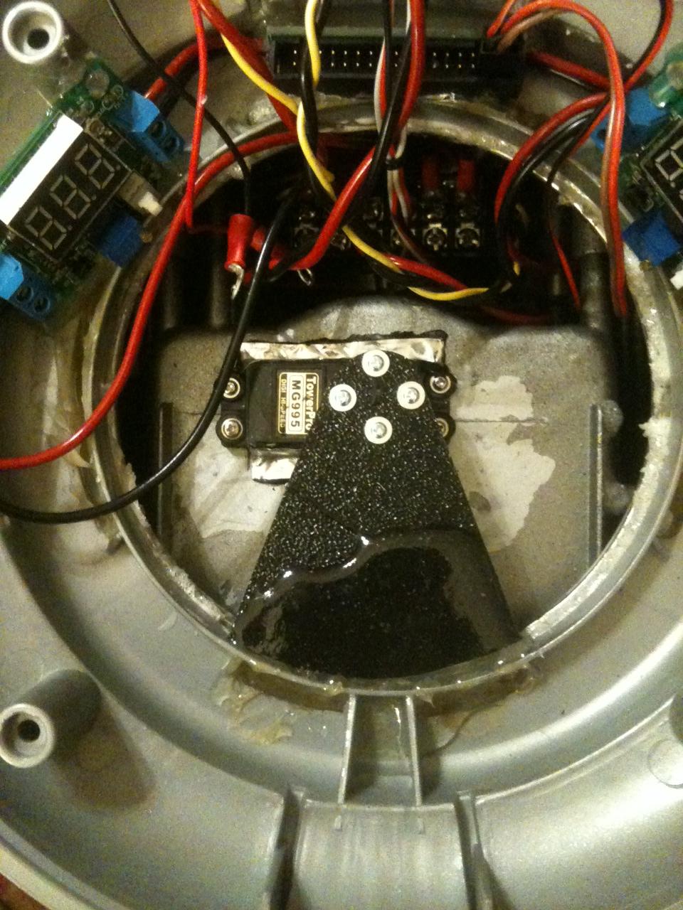
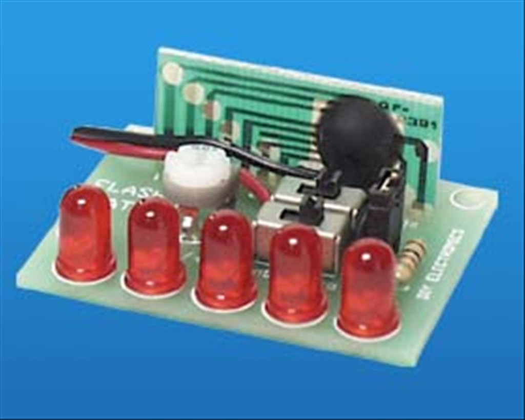
I have mounted clear LEDs in the appropriate colors in the chest at the bottom of the decal and have a flashing circuit that will blink them in the combination as seen on the series. Where the two large round circles are (white domes on the big guy) I will have my ping sensor. I have mounted pager motors in the antenna housings to turn the "sensors" as seen in the TV version. I have mounted red El Wire to his voice plate to emulate the original as well. I have also mounted a series of blinking LEDs to the "brain" section in the bubble.
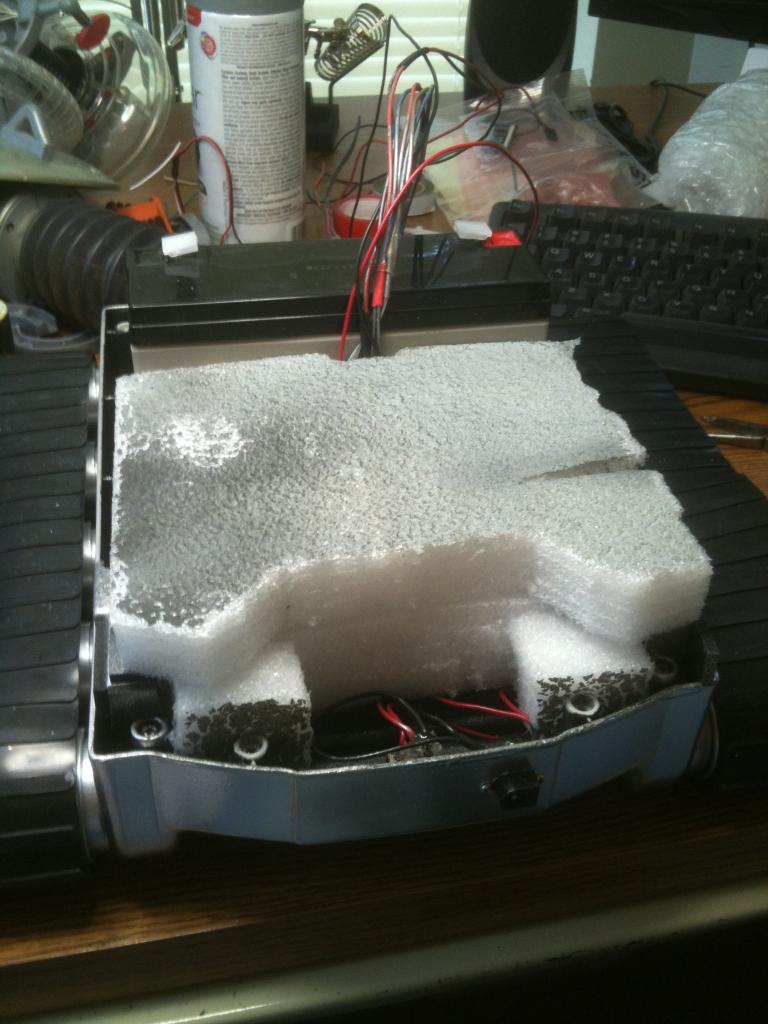
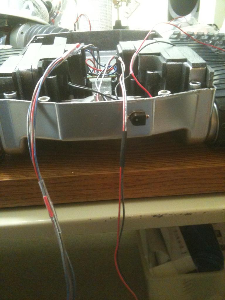
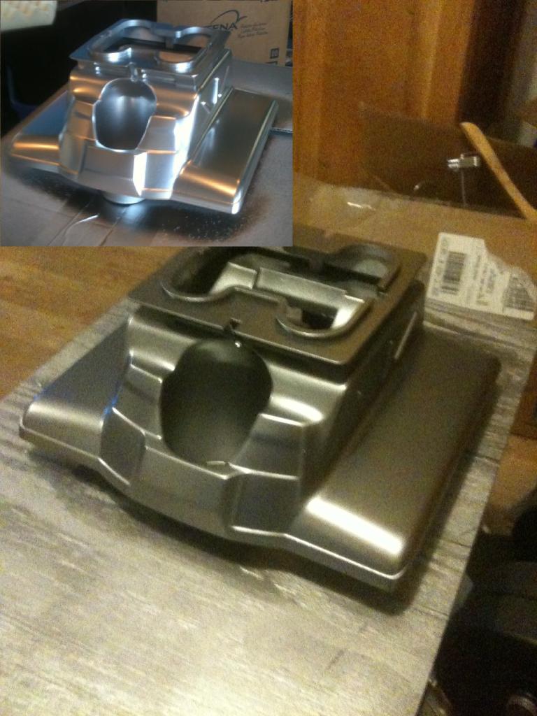
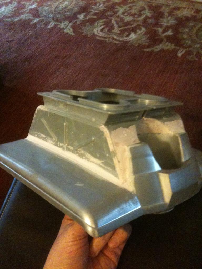
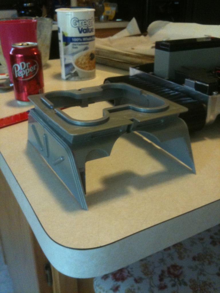
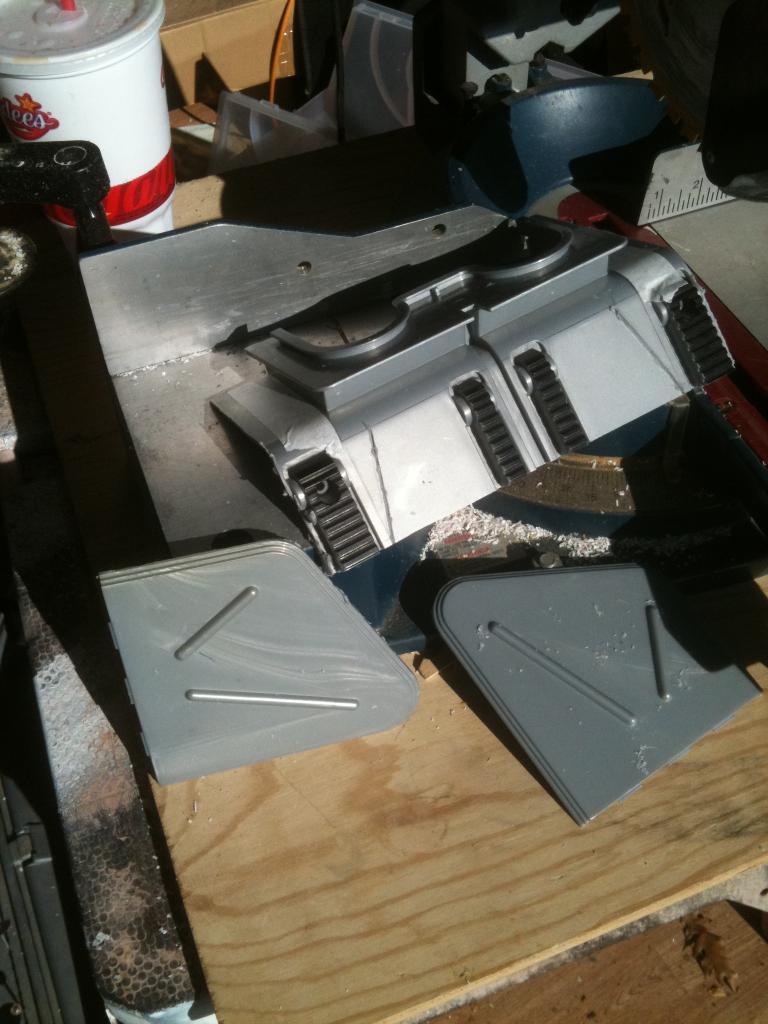
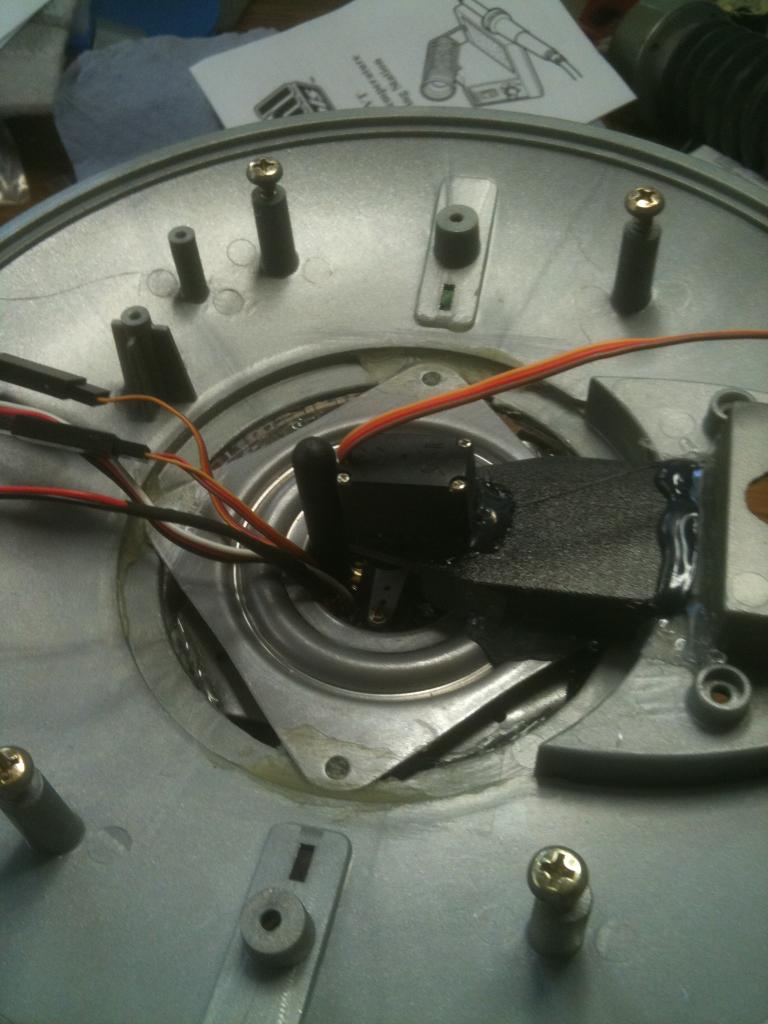
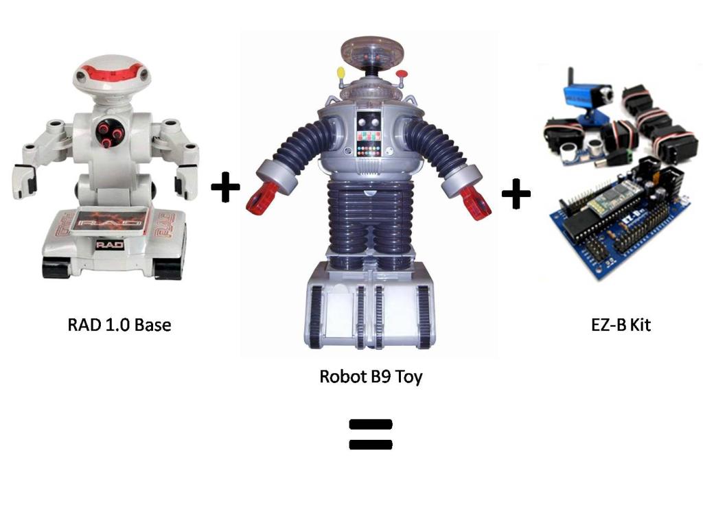
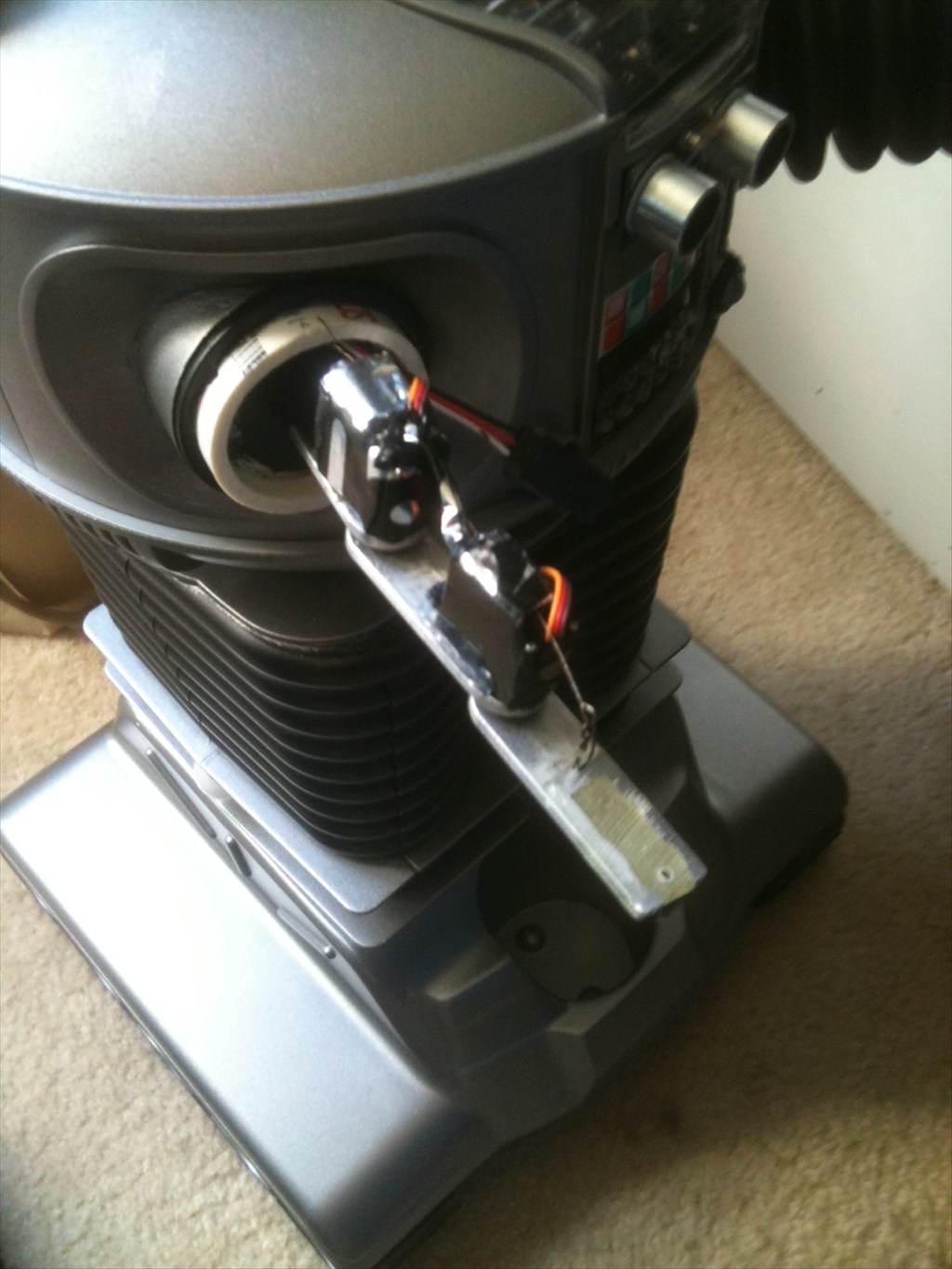
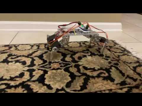
Next is to work on the rotation of the bubble and torso, articulate the arms and claws, and make a real functioning tread section. For the tread section I am adapting the base from my RAD robot. I will keep you posted with pics as I proceed.
Thanks,
Bret
Discover more robots
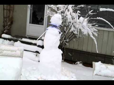
DJ's Cyborg Snowman
Ezang's Happy Crawler 5/18/2021 And New Combination Robot...

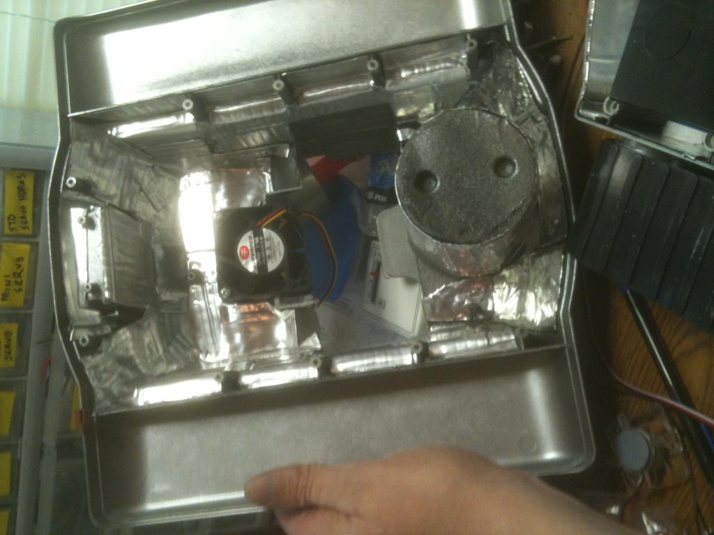
How well did the sound deadening work?
Started working on my arms tonight. Using a ABS coupling as an arm socket I cut out disks from plastic that fit just inside the pipe and the same size as the OD of the pipe. First I started with wood and realized it probably wouldn't rotate as friction free as plastic.
-634771897466093750.jpg)
Next I joined the pieces with standoffs.-634771898236093750.jpg)
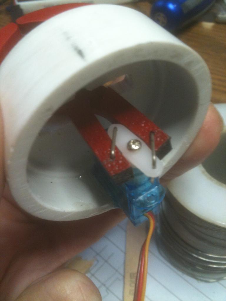
Insert this assembly into the socket.-634771899102656250.jpg)
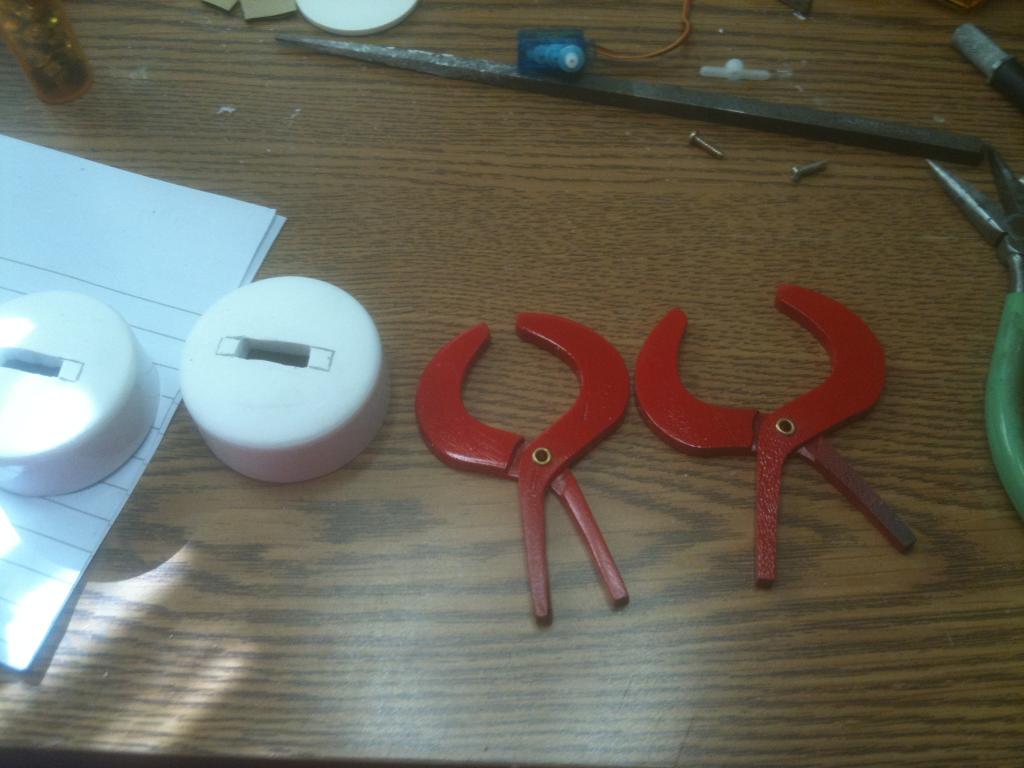
Then the outer cap completes the rotational socket.-634771899822656250.jpg)
The slot is for the arm base.-634771900771562500.jpg)
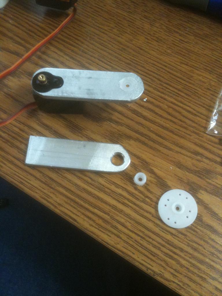
3/4 X 1/8 aluminum bar stock.-634771901301875000.jpg)
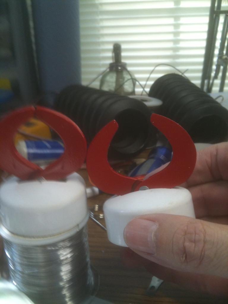
And the whole arm rotates with a servo on the inside. In the video I am actually turning this via the aluminum bar and not with a servo as it is not secure in the arm socket. This is just for demo. Gonna work on it more today and update as I progress.Glued and clamped my rotation mount.
-634772580489218750.jpg)
Then cut my arm pieces.-634772581075781250.jpg)
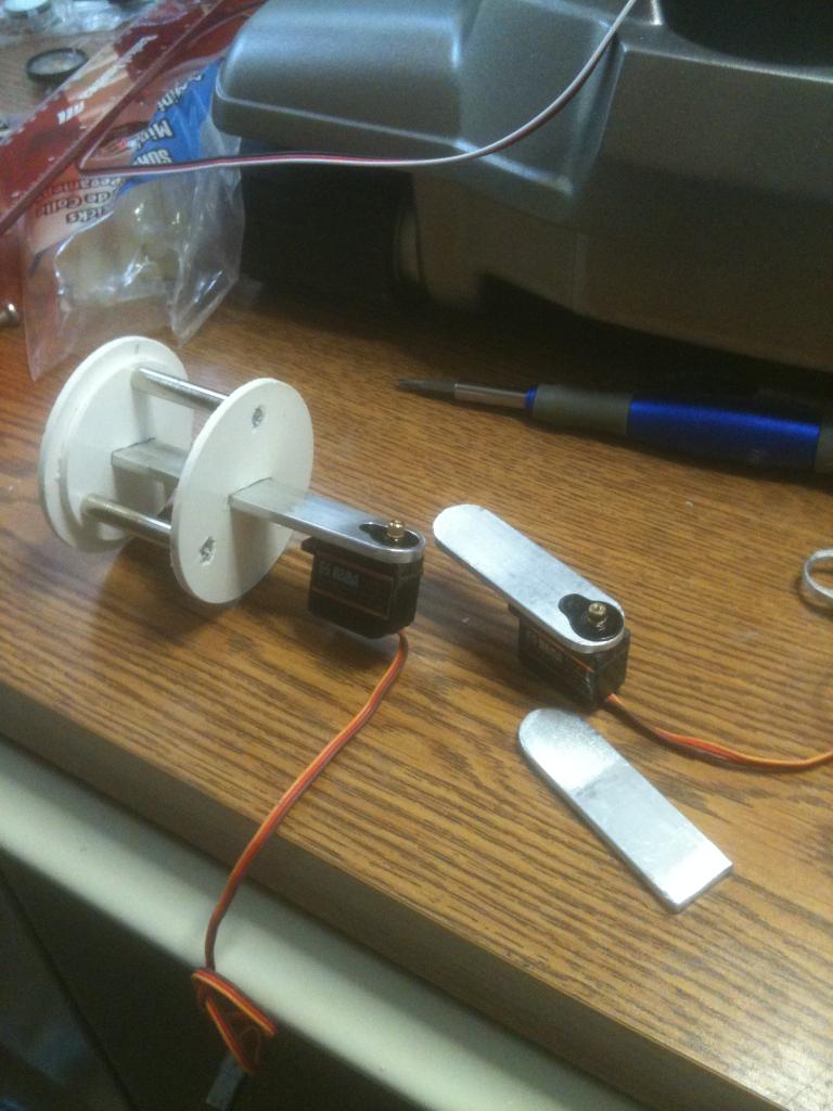
A step down bit and a file make mounting the servos easy.
Now to joint the arm sections and create my claws - oh boy!Looking good! Can't wait to see it in action.
Thanks! Me either lol. So to attache the arm segments to the servos I decided to use the original servo horns mounted to my arm pieces. I needed as low a profile as possible so I cut them down to size and glued them into holes drilled in the arm segments using Gorilla glue expanding glue.
-634773401032187500.jpg)
If this doesn't hold up then I will look at using epoxy for mounting the piece in the hole.I don't know how all this works together. Do you have a drawing or plan your following?
Nah, it's all in my head. But I found out the Gorilla Glue sucks in this application, so it is off to the epoxy.
The epoxy did the trick! Now the arm sections fit on the servos just right. Here I am testing movement with a servo tester. The two servos are tied together with a Y connector so they move in unison. Once I have this mounted in the arm socket then I will have rotation for the whole arm assembly. Cover it with flexible duct and it is pretty close to the real B9. Yay!! cool