Next Hack - Robot B9

bret.tallent

USA
robot video thumbnail

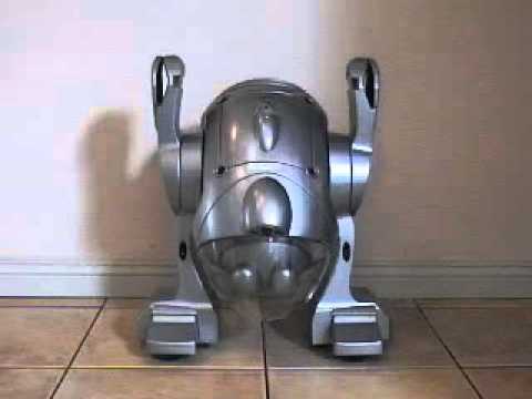
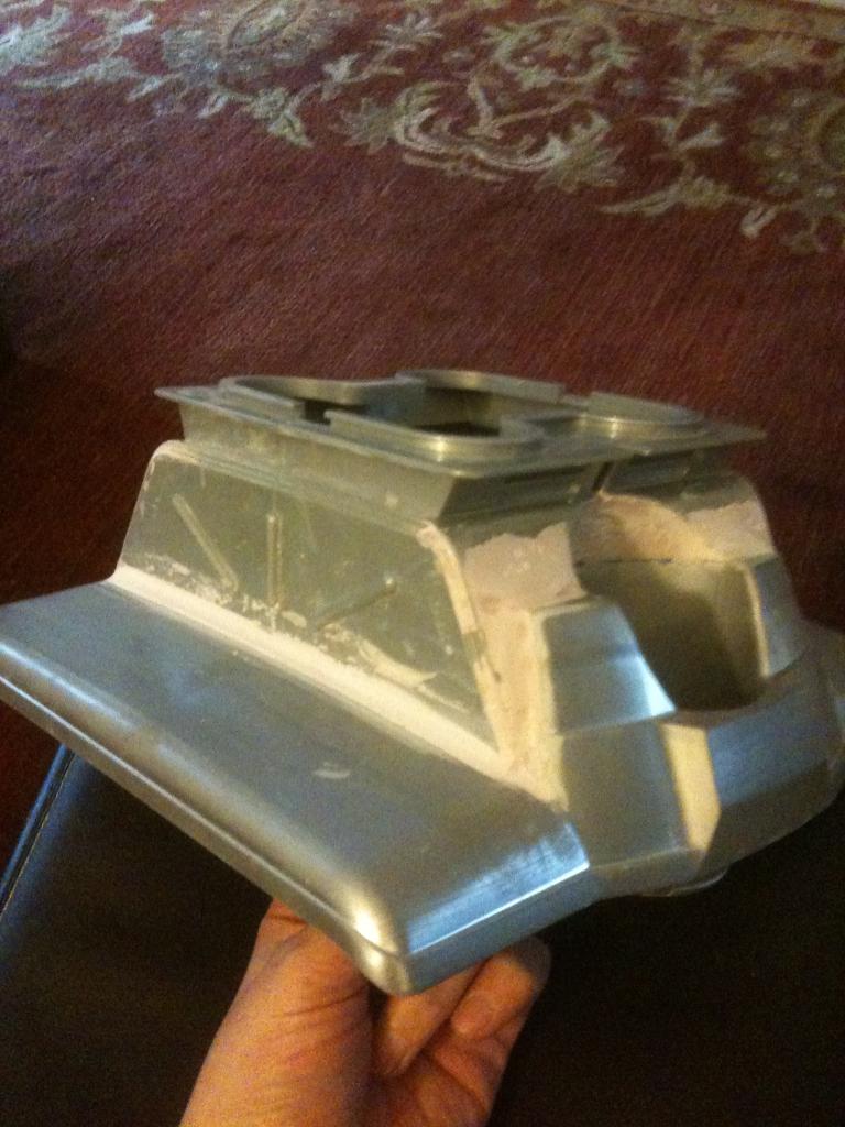
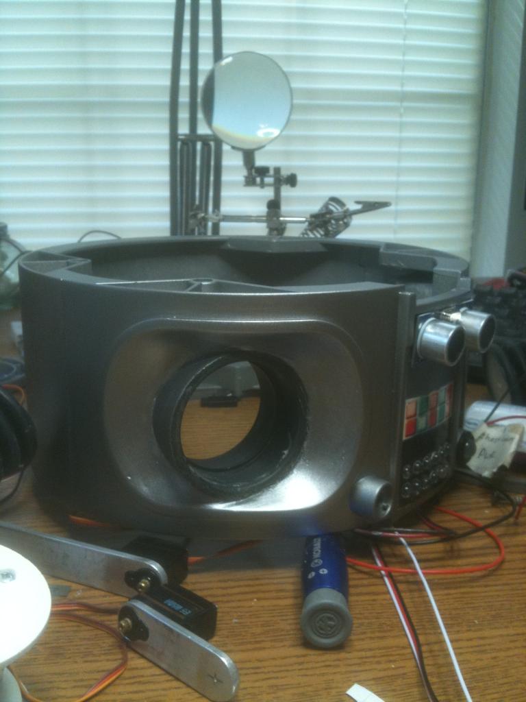
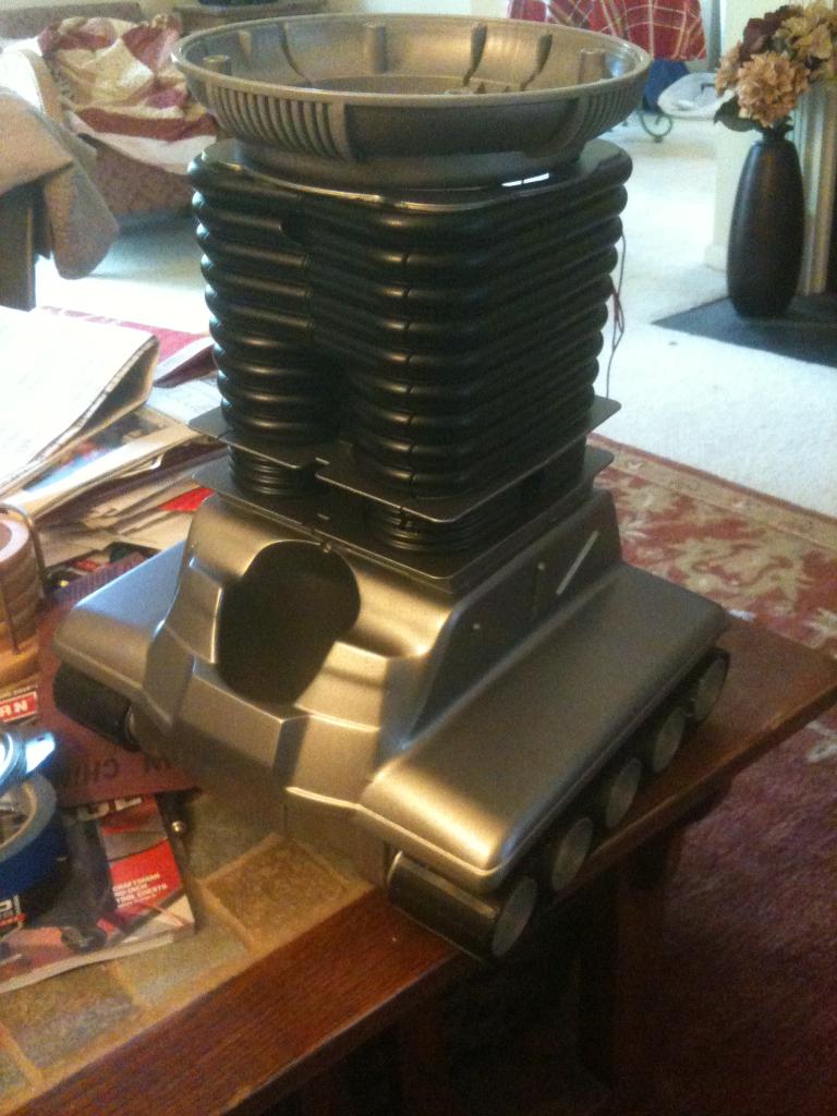
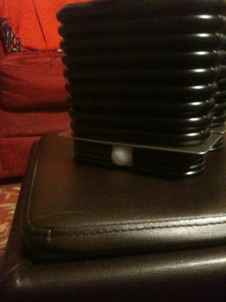
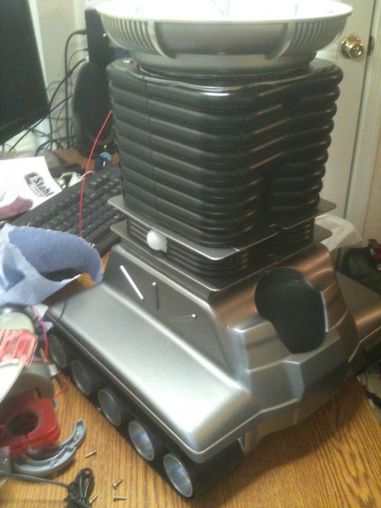
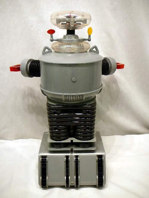
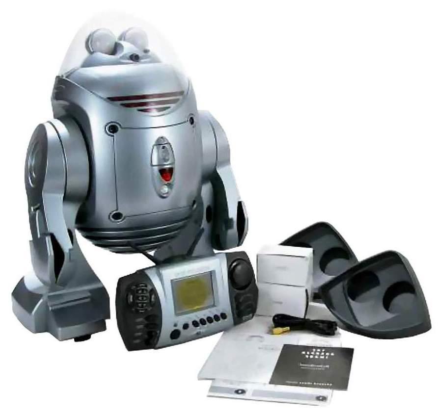
Now that I have finished B.O.B., my get your feet wet bot, I have begun my next hack. This next robot will bridge the gap between Bob and my ultimate big robot. I am starting with a remote controlled B9 toy from Trendmasters. It was very limited in what it did, and the drive section was pathetic, but it was B9!
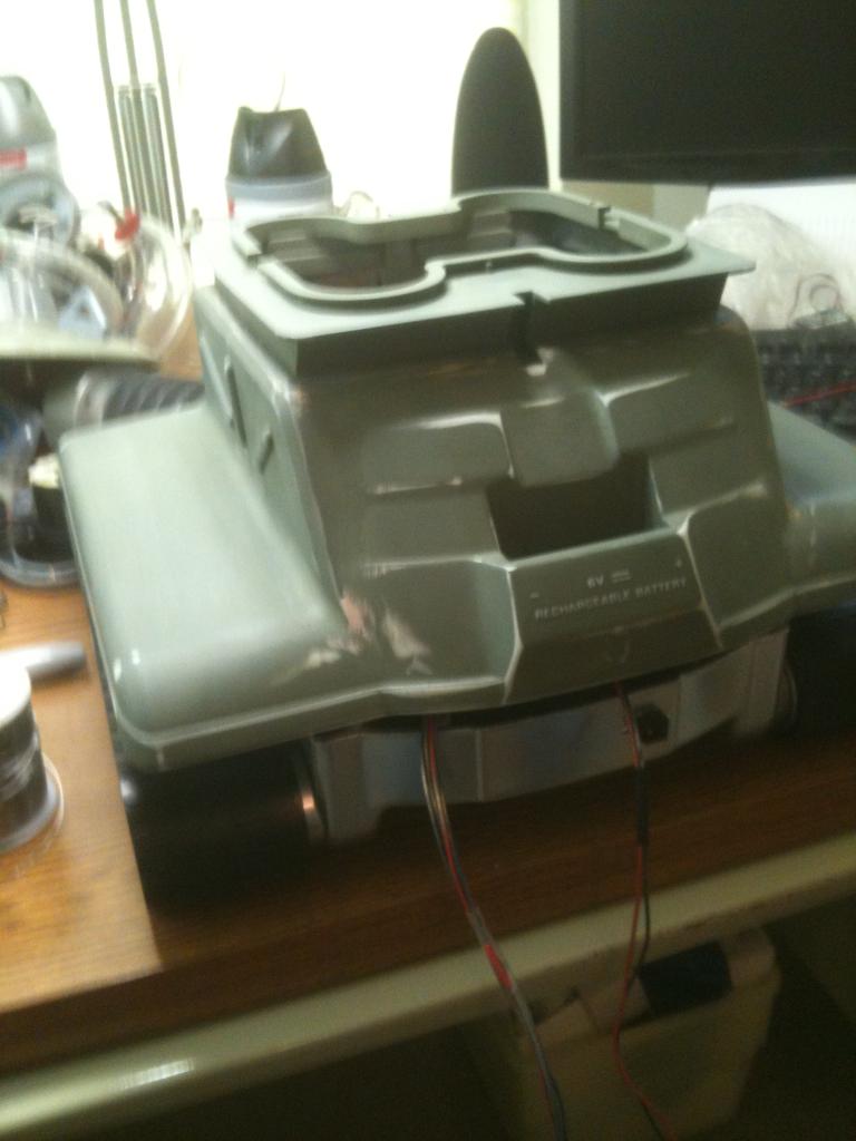
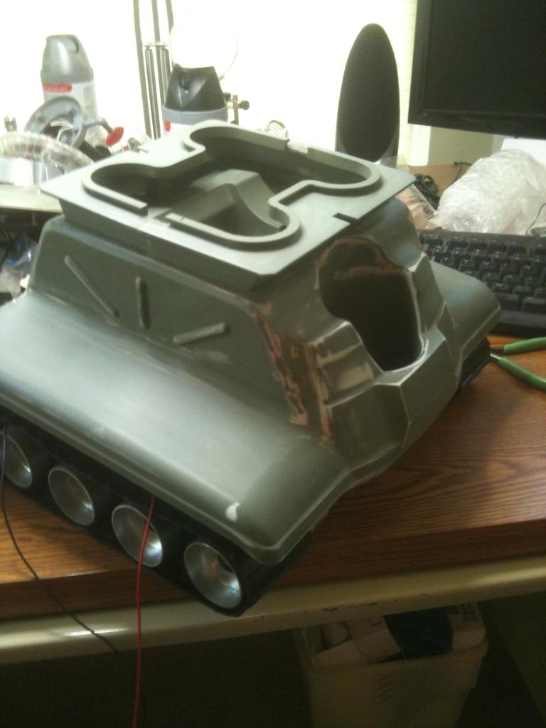
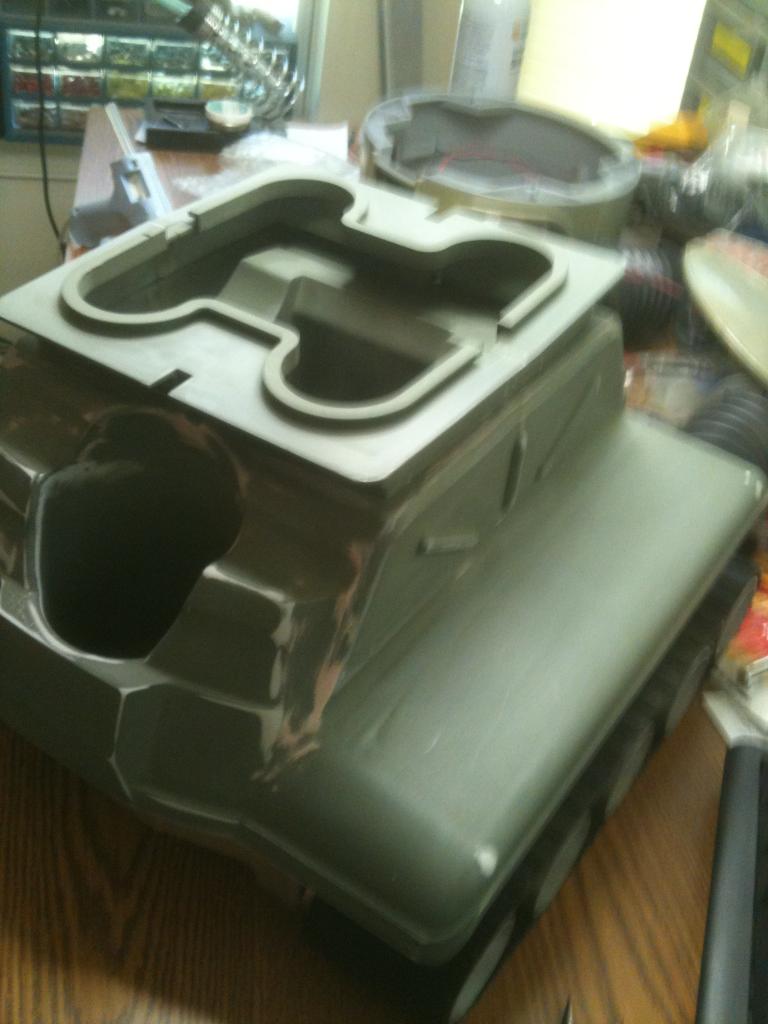
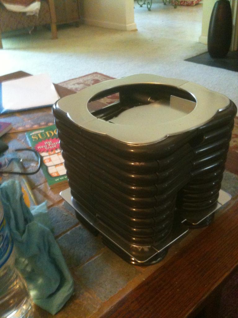
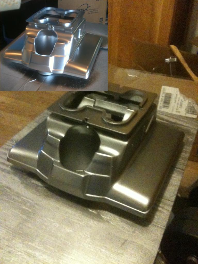
Before Pics: User-inserted image

User-inserted image

User-inserted image Note: the front "lights" in the chest plate is actually just a decal.

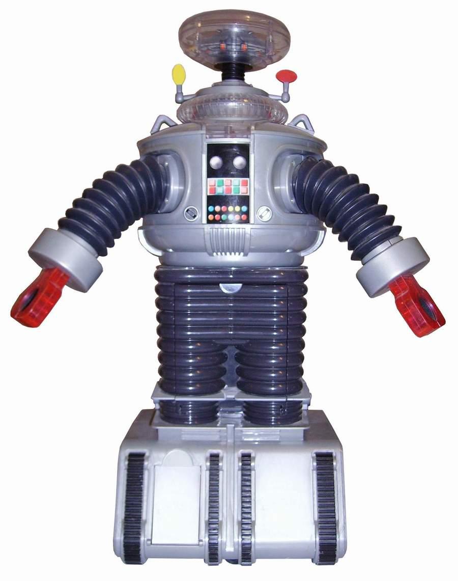
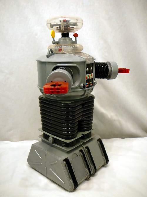
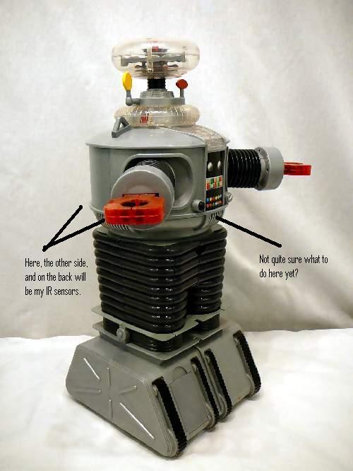
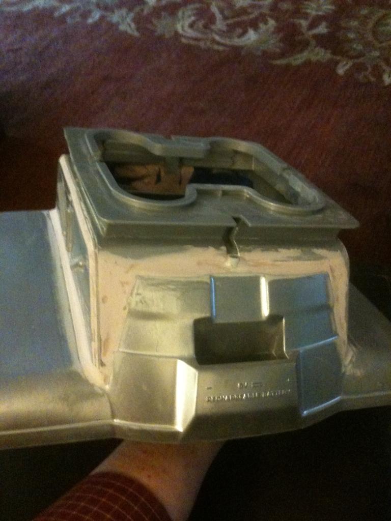
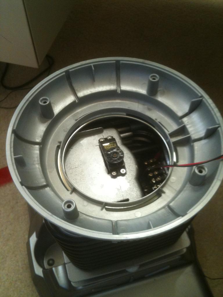
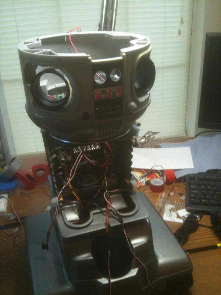
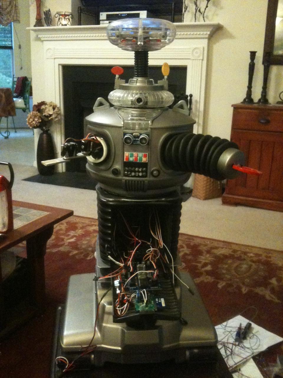
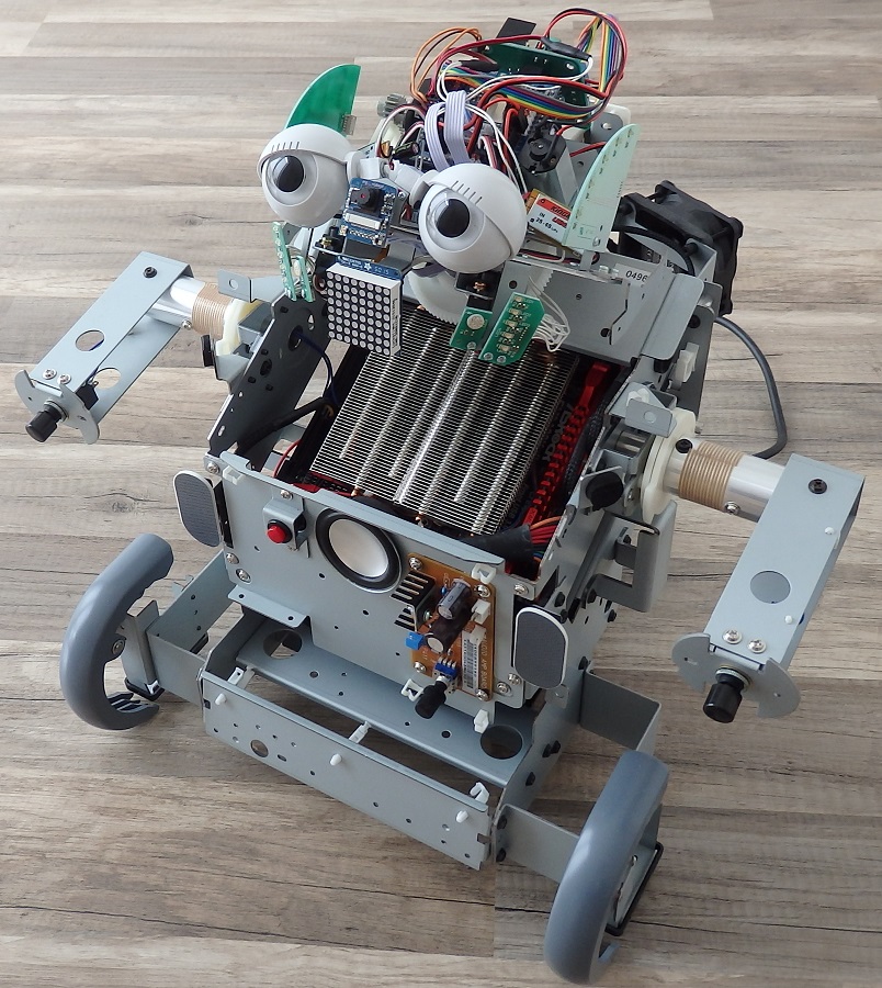
Here is what B9 looks like now:

User-inserted image

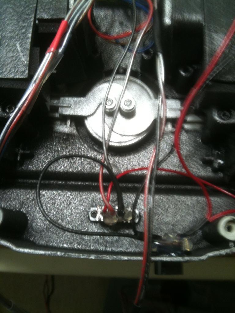
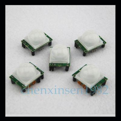
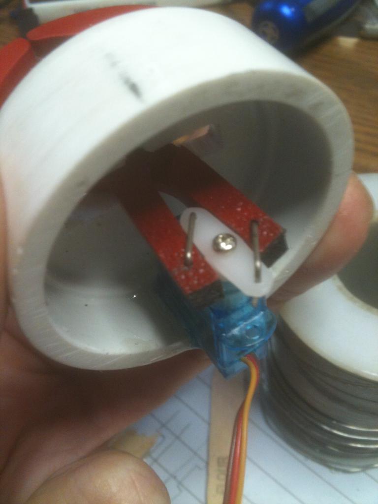
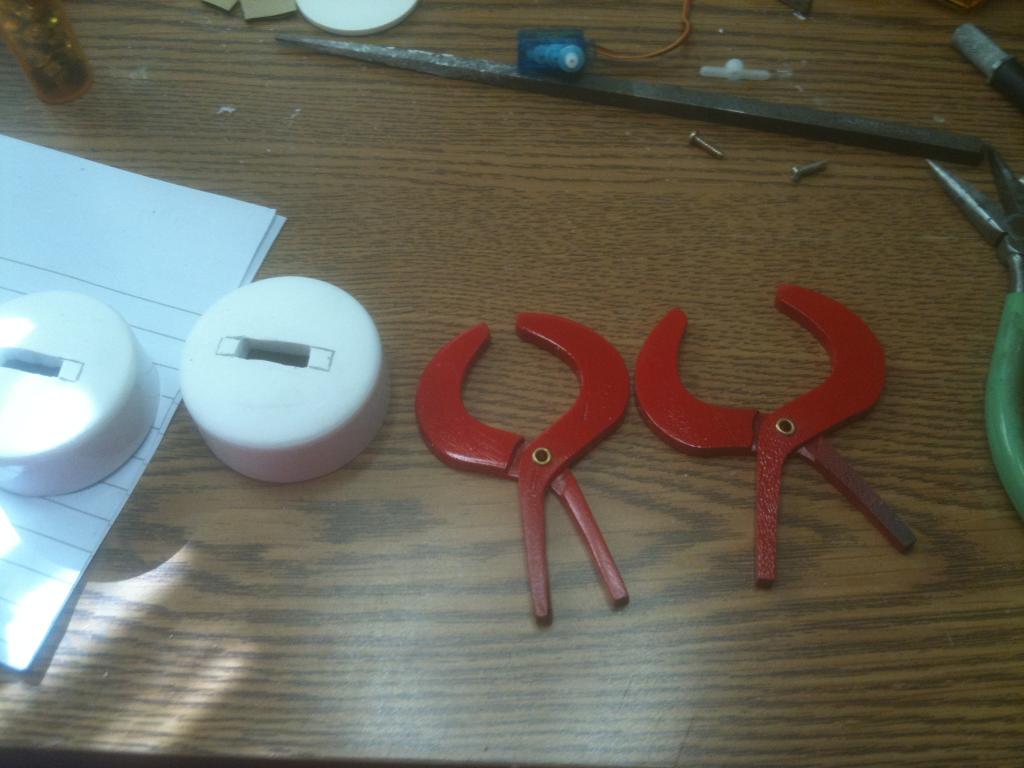
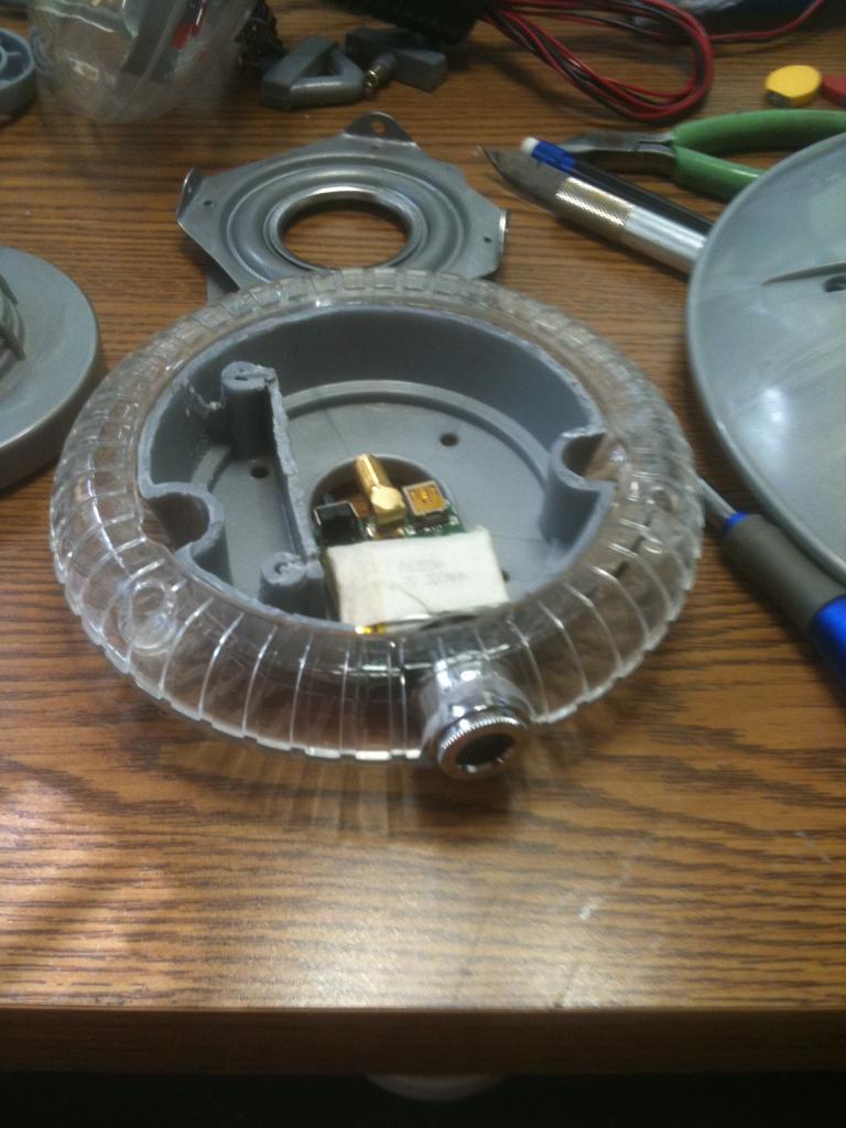
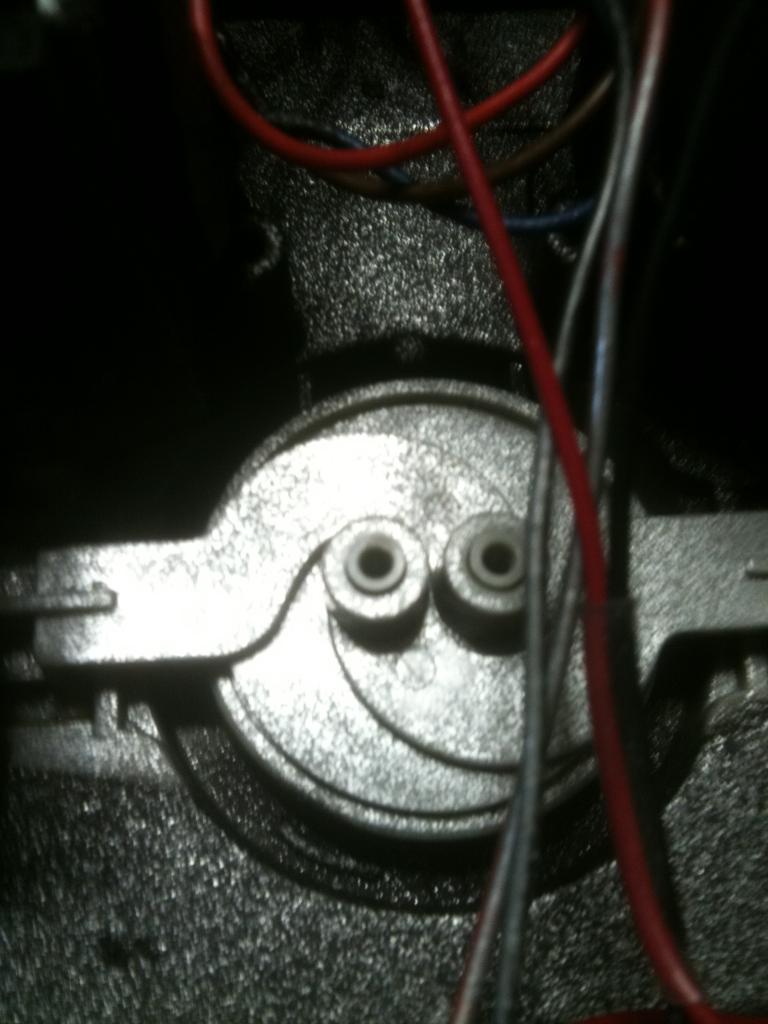
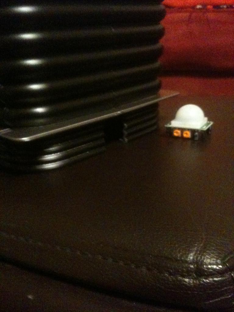
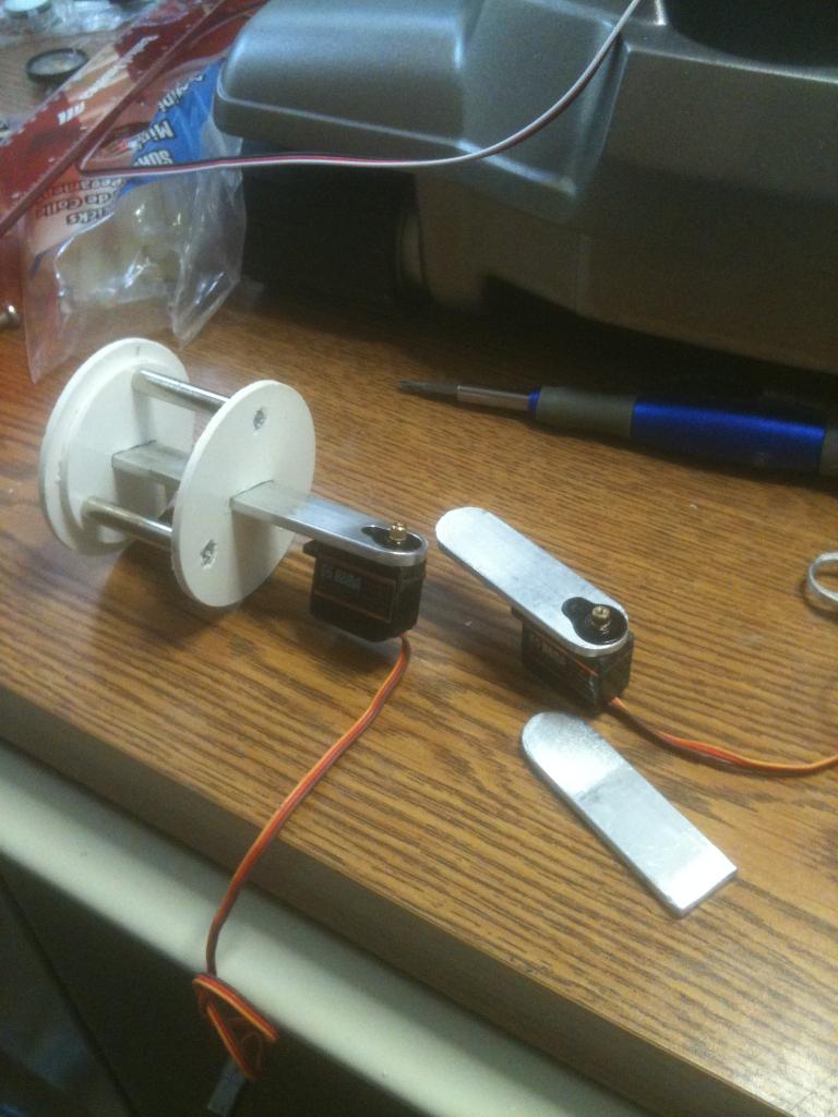
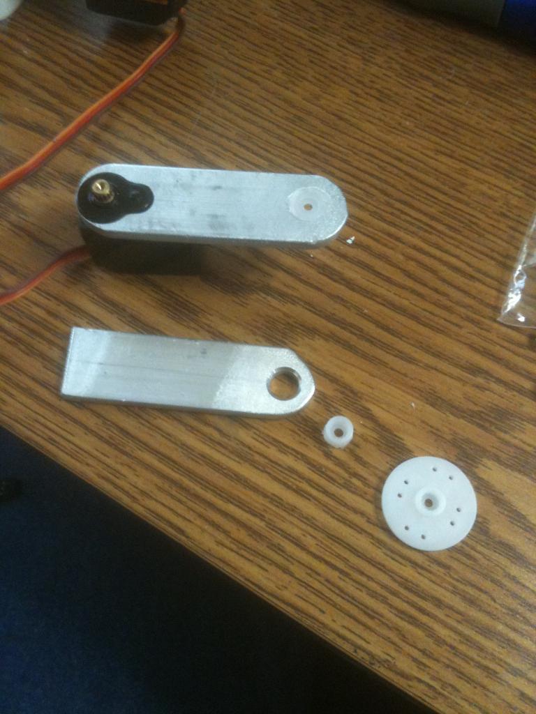
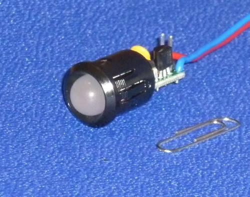
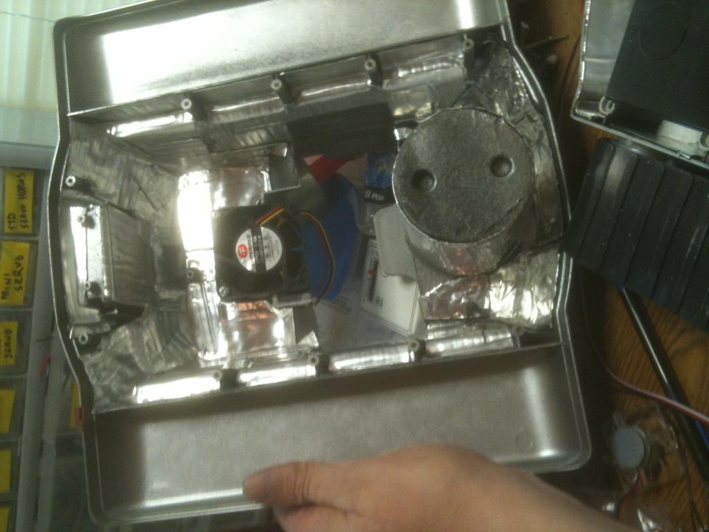
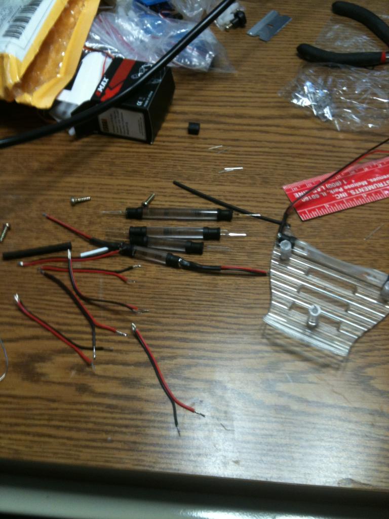
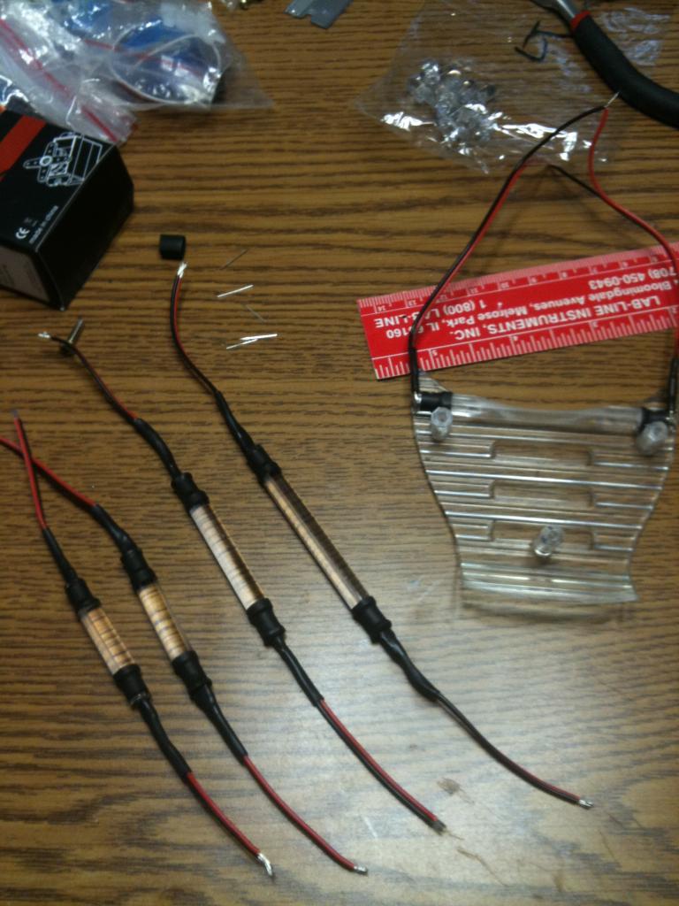
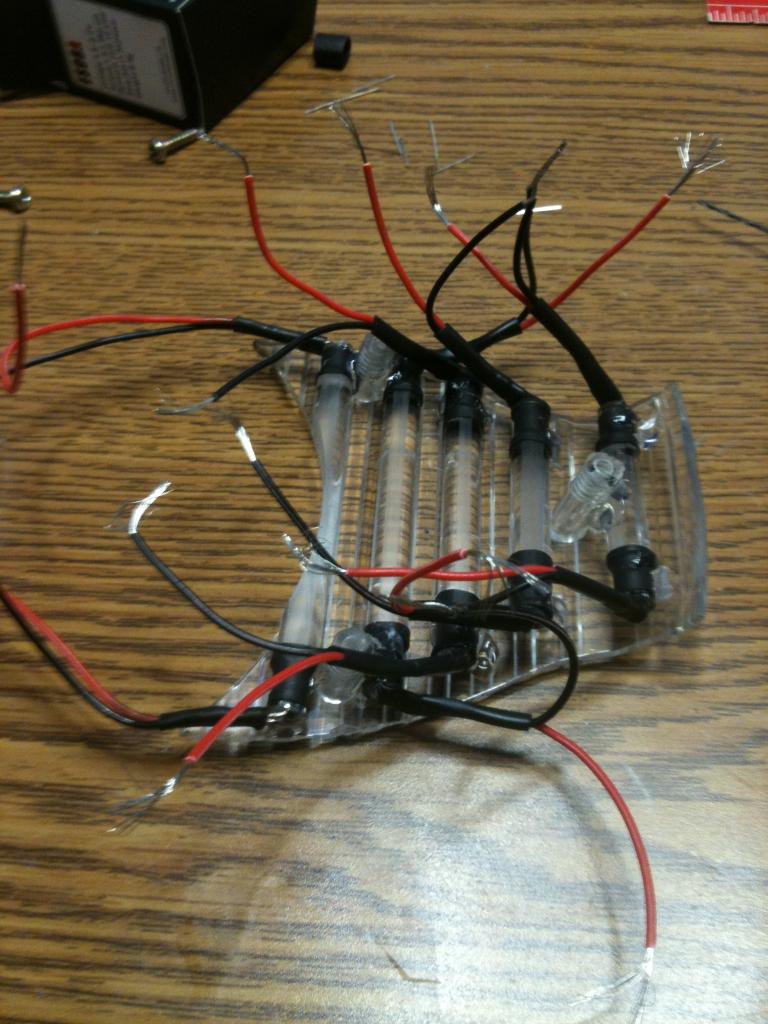
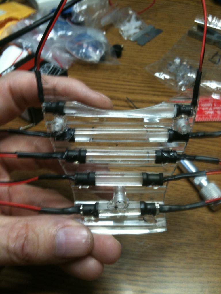
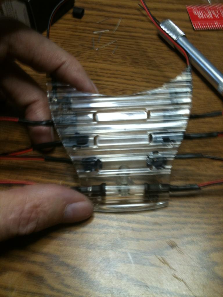
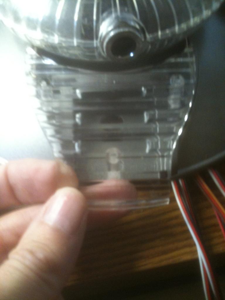
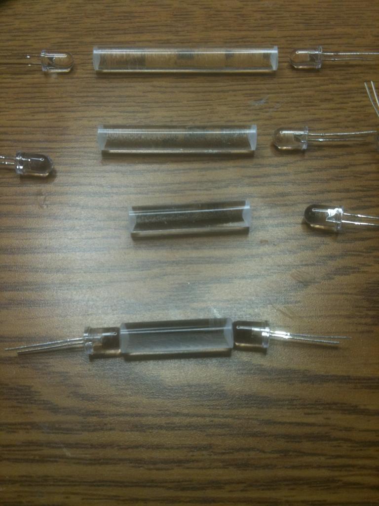
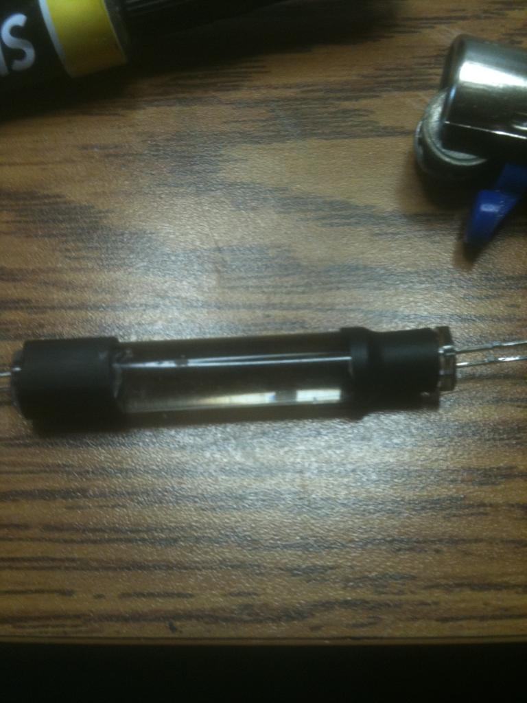
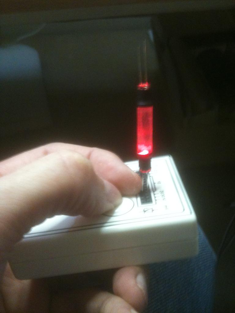
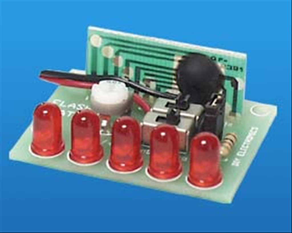
I have mounted clear LEDs in the appropriate colors in the chest at the bottom of the decal and have a flashing circuit that will blink them in the combination as seen on the series. Where the two large round circles are (white domes on the big guy) I will have my ping sensor. I have mounted pager motors in the antenna housings to turn the "sensors" as seen in the TV version. I have mounted red El Wire to his voice plate to emulate the original as well. I have also mounted a series of blinking LEDs to the "brain" section in the bubble.

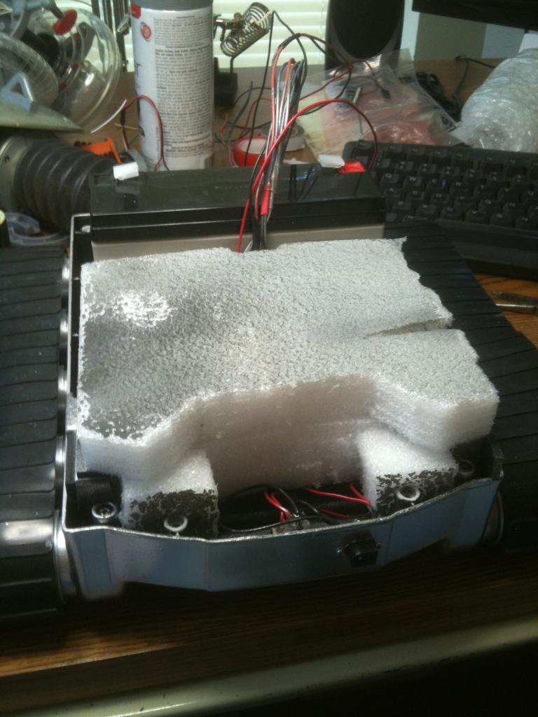
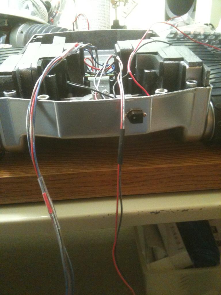
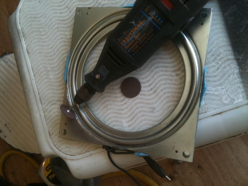
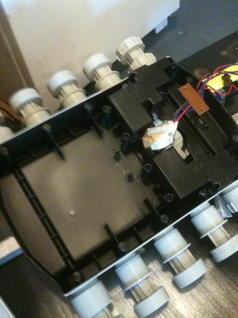
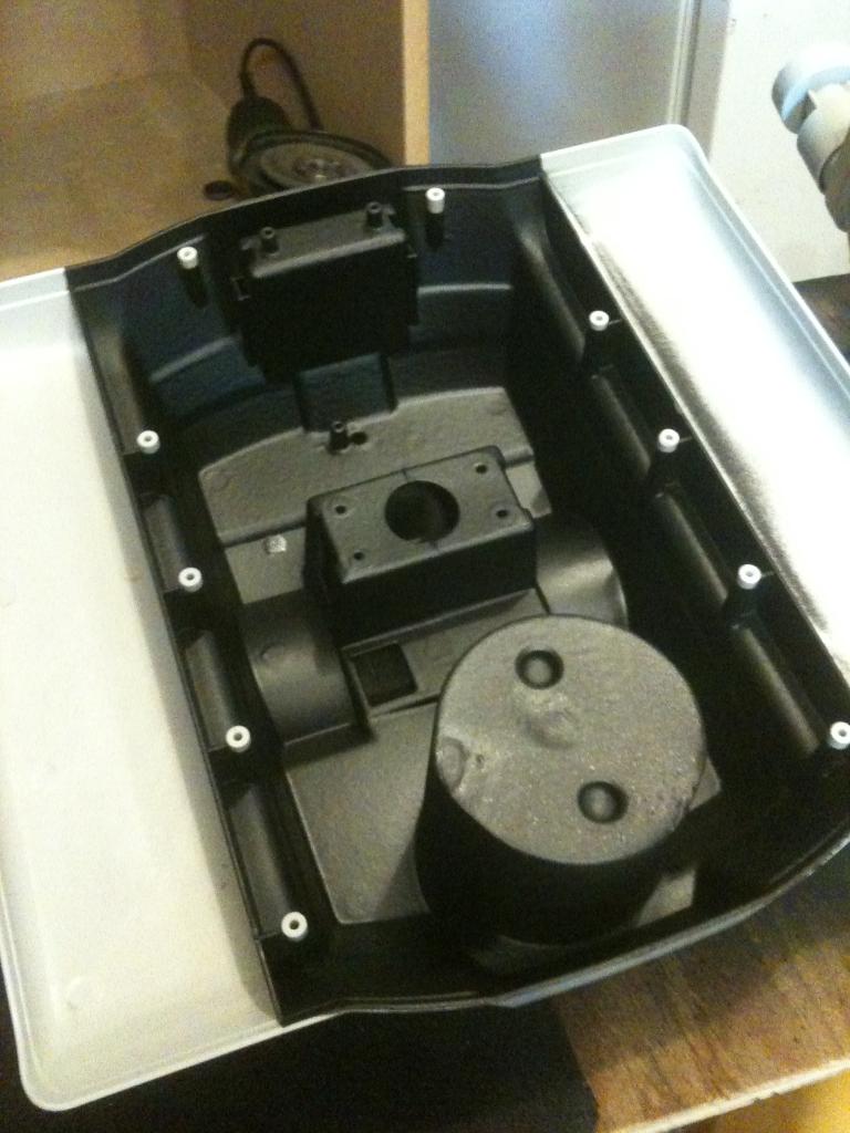
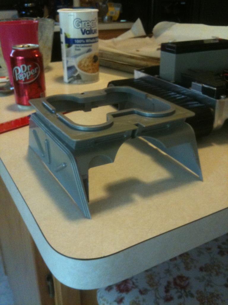
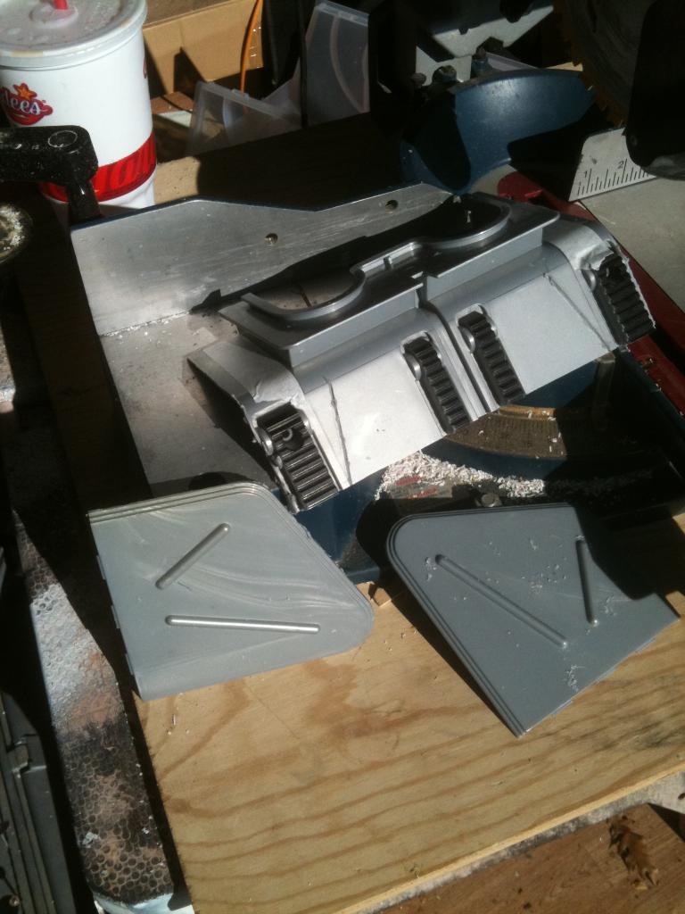
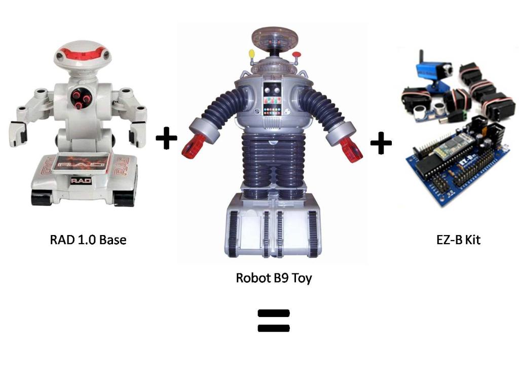
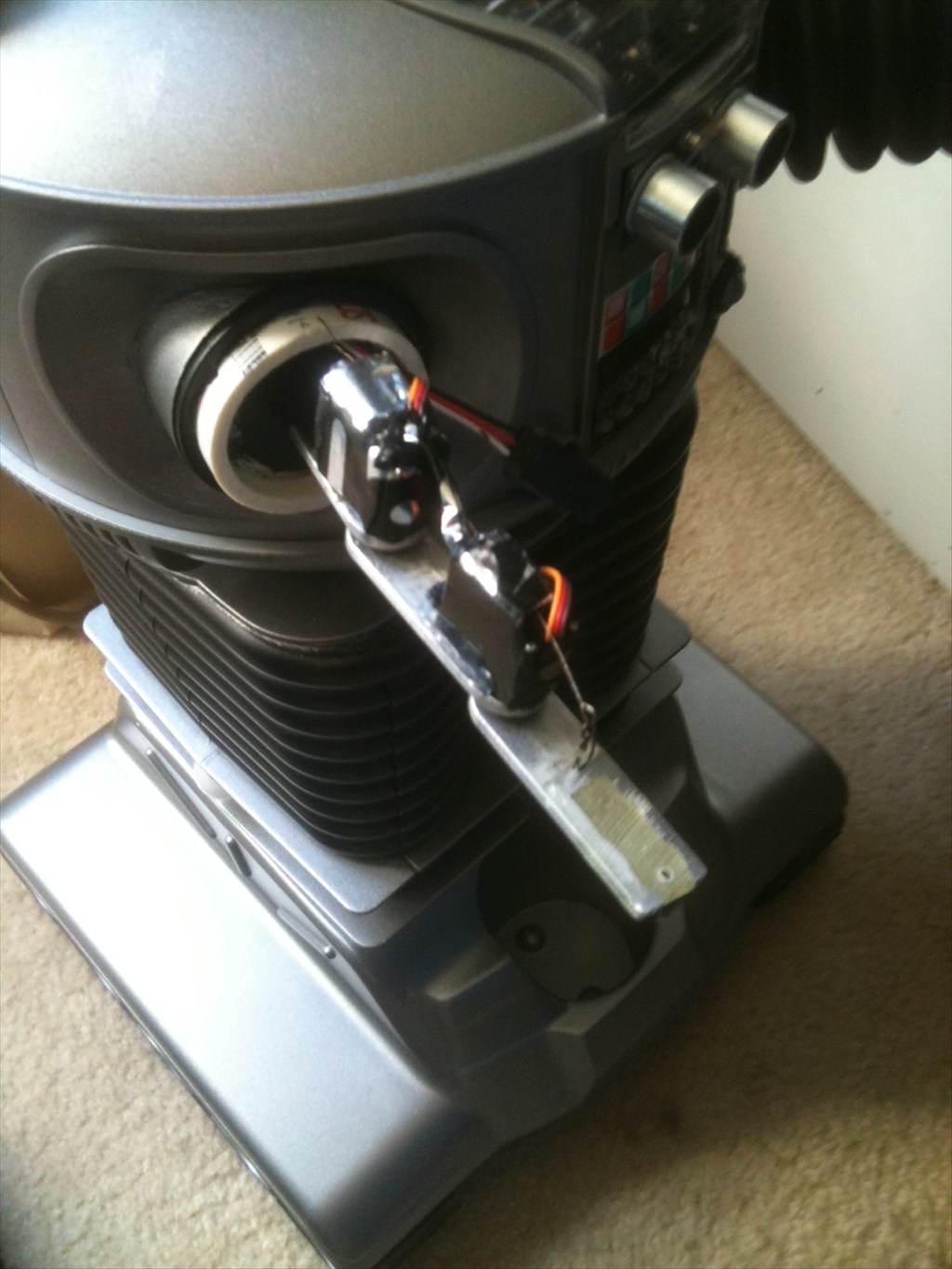
Next is to work on the rotation of the bubble and torso, articulate the arms and claws, and make a real functioning tread section. For the tread section I am adapting the base from my RAD robot. I will keep you posted with pics as I proceed.

Thanks,

Bret

By — Last update

ARC Pro

Upgrade to ARC Pro

Don't limit your robot's potential – subscribe to ARC Pro and transform it into a dynamic, intelligent machine.

#1  

Nice, can't wait to see your future progress!

#2  

how much was the shell....or toy or whatever it was.(lamp?)

#3  

@hoolagen1 - this was a remote control toy from Trendmasters in 1997/98. I paid $79.00 for it back then. Don't know what they go for now but imagine you can get them on ebay likt the omnibots and stuff.

#4  

That's going to be a lot of fun. Looking forward to seeing your progress.

#6  

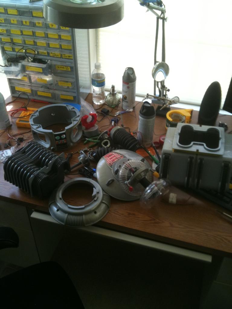
Your picture reminds me of this episode when the robot got taken apart.

User-inserted image

They got him back together though. I am sure that you will too. I look forward to seeing him moving around on his own.

#7  

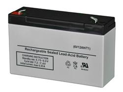
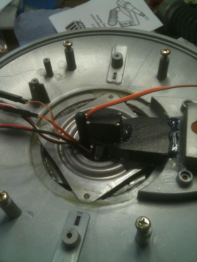
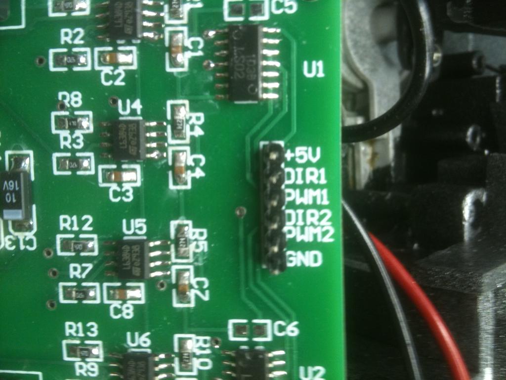
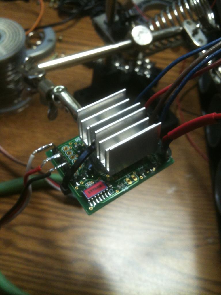
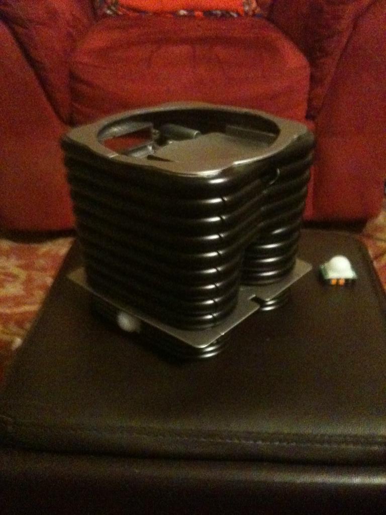
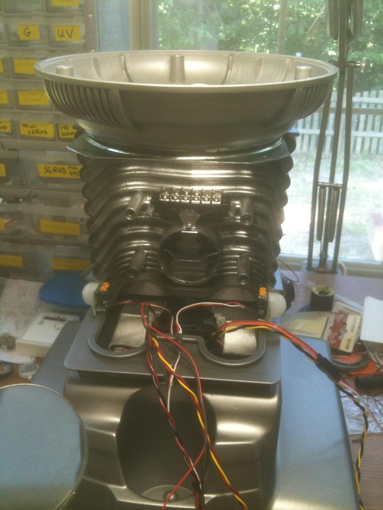
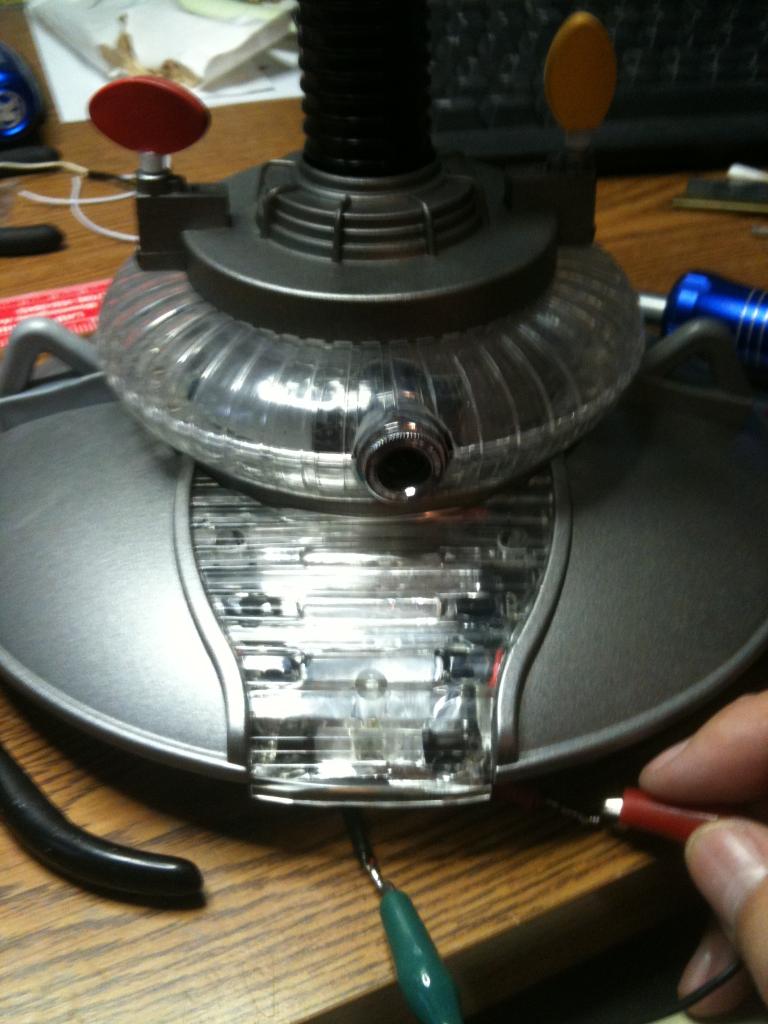
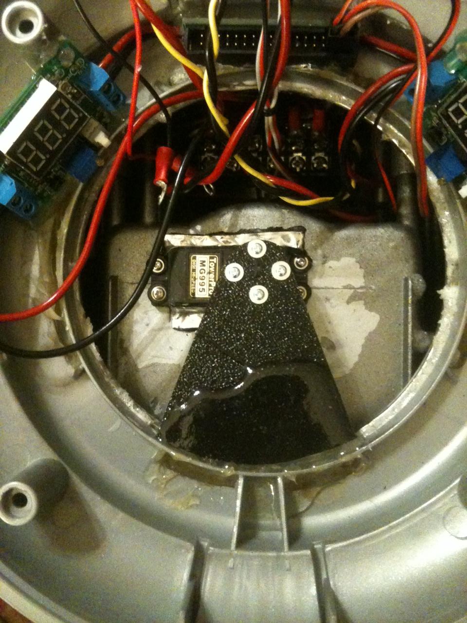
Thanks! - So I have the lights in the bubble and lower chest finished. I also have motors mounted in the radar pieces (eventually these will be controlled via the EZ-B and an H-bridge) but for now I just want to show them working. I am moving my power supply between features just to show you how they work, as I have not ordered my next EZ-B yet (gotta save my pennies). But you sorta get the idea.

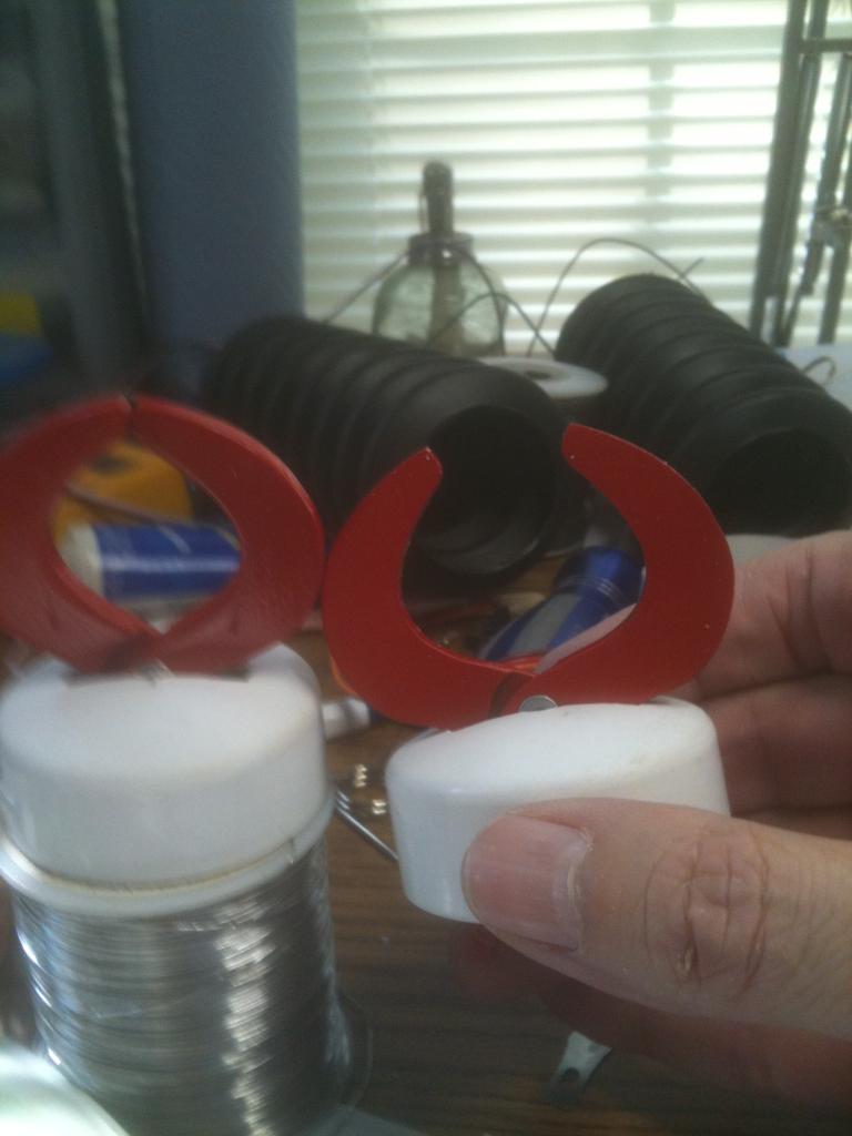
I have a 5 and 1/2" acrylic lazy susan bearing coming in so I can rotate the waste, and a servo attached to the bubble's neck will rotate that. But I will have to do some cutting to the bot to get the collar section to rotate, but that is where I want to mount the camera. I'll have to see what I can do there. I also have a plan to get a fairly full range of movement out of the arms that will mimic the original robot from the series.

#8  

Looking good so far! Can't wait to see it all back together. Any plans yet for the arms? :)

#9  

@ww321q - I have an idea for the arms. I am working on that along with the drive section. As soon as I have proof of concept I'll post some pics and videos. I also think I will replace those pager motors with micro-servos so I can have more control over the movement of his antennae.

#10  

Okay, so I decided to do the noise reduction as outlined by jstarne1 on his build. Then I opened up the base and this RAD drive is very different from my Omnibot. Way too many issues with crevices and such to work with the dynamat. So I have decided to use undercoating. After several coats I feel that everything is well coated and should quiet it down considerably. User-inserted image

User-inserted image After it all dries well, then I'll get the motor controller and batteries set up. I plan on using the original wiring in the base, along with the on/off switch. I will also mount my charging port here in the base. I plan on two 6V batteries wired to keep it 6V but increase the amps. This should give me a longer run time.

#11  

Bret,

That is looking great! I am curious to hear how your undercoating went...how many coats did you use and where did you get it?

Again....B9 is looking pretty sweet!

v/r

Kevin

#12  

Hey Kevin, I used standard automotive undercoating that I got at Lowes. I put two coats on it. It's basically a spray on rubber coating and two coats is about 1/16" thick. The can said it was sound deadening, so we will see. I also used a ton of lube in the gear boxes - Lithium-Graphite. That should also help with noise. If I think it is still too noisy, there is enough room to add additional insulation on top of the gear boxes. Right now I am looking at batteries that will be placed in the drive section for balance.

#13  

Bret I tested tool dip from lowes today , its a molasses.consistancy and.paints on with a brush , I found the spray in stuff to take many Coates. Tool dip rubber in a big can .is 5 to 6 bucks. It's crazy how.loud these rads are stock lol. If you descide to add tool dip rubber it can paint right over the spray on Coates you made. Looks awesome very clean man , I like it. Is this.the b9 base?

#14  

Yes, this is the base for my B9. This is where I will use that uber cool motor controller I got from you...

#15  

Right , can't wait for my project to reach a good stopping point so I can start fiddle darting around with the rad base.

#16  

2 ub645 batteries fit side by side on their edge and still have room in the front for ezb. You will need to trim away at that cup holder though. User-inserted image

#17  

Sorry man I posted the wrong pic , here's the pic showing the batteries strapped down with Velcro wire tie on their.edge. User-inserted image

#18  

I hate giving up that cup colder though, the perfect place for him to bring me a beer! I actually found this battery, that with a little modding, I think I can fit behind the cup holder. User-inserted image The dimensions are 6" X 2" X 3.7" (LxWxH) - it is 6V 12AH and only $14.00

@jstarne1 - what are your plans for your RAD base?

#19  

I measured , keeping the cupholder is a no go ,

#20  

@Josh - I went ahead and ordered that battery. I will just have to see how I can fit it in and if the cup holder goes - oh well. But I like the idea of staying with the 6V and getting more than twice the AH. I have to add a piece to the top so the base can mesh up correctly with my B9's leg section - so maybe there is some room the for mods to help with battery placement. I think I am going to take your advice on the plasti-dip for the motor compartments at least. I kind of wish now that I had measured the db before and after to see what each change does. Oh well. The cool thing about the leg section is there is a storage compartment that opens from the front that will easily house the EZ-B and give me total access to it.

#21  

Sweet , so is the rad drive going to be hidden or are you gonna just sit your b9 ontop? Postba pic:) you know how I love pics lol

#22  

You could just cut the cups bottom out and trim out about 1.75 inch then glue the bottom back on. It would just be more shallow that originally. I'm pretty sure auto correct screwed up my grammer lol.

#23  

So this weekend it is the drive section. Here is the RAD base I am using: User-inserted image And the battery:

User-inserted image Then I have the B9 base I need to blend with it so the leg section can attach.

User-inserted image

User-inserted image

#24  

Sweet that's great , so you managed to turn it sideways :). Does it fit with top on?

#25  

No, it's too tall. I will need to cut out so it can stick up through. But it will be covered by the B9 piece once I get that cut to fit.

#26  

This would fit under.your b9 all hidden like... User-inserted image

User-inserted image

It's a rover.5 smaller footprint. 9.5 inches should fit.under your b9 without hanging.out. its 45 bucks , 4 motors , adjustable track length too. It's the.rover 5

#27  

That would be perfect - if only I hadn't already invested time and money into the RAD base. But that 45 bucks is a camera, you know? Woulda, Shoulda, Coulda - oh well. But I also like the footprint of the RAD base to make B9 more stable. He is kind of top heavy. And we'll have to see how well I can blend the two bots.....

#28  

Okay, I made the mods to the base to fit my 6V 12AH battery - and keep my cup holder: User-inserted image

User-inserted image

#29  

Mods to B9 base: I had to cut off the side panels so I could narrow its base. User-inserted image Then I needed to cut out section to fit over the hump in the RAD base.

User-inserted image Then I had to shorten the side panels and give them a slight curve to match the contours of RAD

User-inserted image Next I need put all the B9 pieces back together and mount it onto the RAD base with plastic epoxy.

#30  

@Bret,

I think it is looking great.....well done mod. I like how the RAD tracks set outside the B9 base, I like to see the tracks moving ..personal preference....it will go together nicely It easy to start sinking big bucks into this stuff..

v/r

Kevin

#31  

Here is the completed mod to B9's base so it will fit on the RAD drive section: User-inserted image And here is what it looks like sitting on the RAD drive section - note I can still use my cup holder. Yay! User-inserted image

#32  

Lmao , bring me a beer ! I command you with ezb

#33  

You could put a spring mechanism on the bottom to have it pop the beer out on command!

#34  

I thought about a servo that could raise it up, but the spring is interesting too. You could make it sort of like a dart gun so that you engage the spring when you put the beer in, and use a servo to release it. It has potential for damage, I like it!

Spain
#35  

Fantastic adaptation of the two platforms! and also capable of carrying beer that, that if a service robot! :D

#36  

Kkeast , I agree , I absolutely love tracks , they are an icon that we all imagine when we think.of a cool robot

#37  

Gotta Love Bondo! User-inserted image ...and sanding...and sanding

User-inserted image ...and then sanding some more. I should put on my last skim coat this weekend and get all the sanding done. Then I can paint it and complete the drive section.

#38  

Just received these last night - IR sensors for Robot B9: User-inserted image

100% BRAND NEW! Weight: 33g (approx) Color: White + Green Dimension: 3.2cm x 2.4cm x 1.8cm (approx) Infrared sensor with control circuit board The sensitivity and holding time can be adjusted Working Voltage Range: DC 4.5V- 20V Current drain:<60uA Voltage Output: High/Low level signal:3.3V TTL output Detection distance: 3--7M(can be adjusted) Detection range: <140 Delay time: 5-200S(can be adjusted, default 5s +-3%) Blockade time: 2.5 S (default) Trigger: L: Non-repeatable trigger H: Repeat Trigger (default) Work temperature:-20-+80C Trigger Method: L unrepeatable trigger / H repeatable trigger

Note: Sensitive Setting: turn to right, distance increases (About 7M); turn to left, distance reduce (About 3M) Time Setting: turn to right, time increases (About 300S); turn to left, time reduce (About 5S).

Package Included: 5x IR Detector Module

And I think I will mount 3 of them in his lower torso on the sides and back - nothing gets past B9...

User-inserted image

#39  

@brett , if I can recommend Somthing that will save.you.a.great.deal of time finishing the.Bondo. when you.believe your on your last round.of Bondi.and sanding , spray three thin layers a couple minutes apart of.primer. then give.it.your.final sand using 400 , then spray on another coat.of primer and 600 or 800 grit will completely insure.that.its.smooth agianst your plastic and no sanding marks that.will show through your paint job. Sanding sponges from lowest are.usually good.for.this. ps. Do not buy.high.build primer! It stays wet a long time and multiple.layers aren't possible as.it just stays mushy. Either regular black primer or etching primer because your.working.with plastics.

#40  

jstarne1;

You're a freaking Genius!!!!:) Always Great Advice!

#42  

@RR333 Thanks , I feel like a million dollars with that.comment. I love helping everyone get their projects done , sometimes even more than doing my own.

@brett I don't know if you ever done this but get warm water , put some dishsoap in it , like dawn. Just so it is a little soapy. Dip your sandpaper in it every minute or two its way less messy than all the dust. I do mine over.the.kitchen sink. You will see it sands much easier with less resistance , easier on your fingers ;)

#43  

No Prob, You've given me great advice before and I swear I learn more just reading your posts helping others:) Thanx! "We are All in this Together!"

#45  

jstarne1 a product I started using for restoring rubber and plastic parts is Mothers Back to Black. It's kind a milky like 50w Armor-all. only better. It's was made for black car bumpers to bring the color back. LOL I've never used it for that. Comes in a Red bottle. Every body should have some.

#46  

I can't wait to see B9 on top of the new wheels/tracks !:) JW

#47  

I have installed a recharge jack in the back and am using the original on/off switch. I have also grouped my wires for the motors and power. User-inserted image

User-inserted image Thanks to input from jstarne1 I have primed and water sanded the newly melded bases of B9 and RAD. It is not perfect, but good enough for paint (for me anyway).

User-inserted image

User-inserted image

User-inserted image And here is the leg section with new paint - I still have to clean off the silver that worked its way under the tape, but I like the color.

User-inserted image

United Kingdom
#48  

HI Bret

great job of joining the two robots together . It looks like they were moulded that way . A fantastic job .

Steve_c

#49  

Thanks Steve_c. Here is my drive section with the battery installed and some more sound deadening material (foam core this time). I hope this all helps to keep it pretty quiet. User-inserted image

United Kingdom
#50  

Hi Bret

I had to quieten up a genarator on my boat , I put sound deadening tiles around the inside of it box and poly foam under the lid , It was alot quieter .

Thats what youve done there so it will be much better.

Steve_c

#51  

Thanks, I think so too. I finally got the new RAD/B9 base painted. Not perfect, but I like it. User-inserted image

User-inserted image

User-inserted image After some good dry time I am going to give it a coat of carnuba wax to protect it and then mount it to the drive section. Then comes the leg section and some more wiring of sensors, motor controller, and install of the EZ-B.

United Kingdom
#53  

Someone would have look VERY close to see any imperfections , B9 would be well within its rights to zap them with a getlost ray. ;)

#54  

Bret did you clear coat it ? Some of that silver paint fingerprints really bad. I never tried waxing it though:) JW

#55  

Only wax auto grade paint. It nasties up spraypaint.

#56  

No, I didn't clear coat it. I know what you mean about the fingerprints, I already messed up one spot (but not that noticeable so I am not going to worry about it. But I am going to try the wax on an underside first.

#57  

I would suggest doing what ww321q said and clear coat it.

#58  

Do a test first cause it could cause the paint to look grey instead of silver :)

#59  

Do I need to sand it prior to applying the clear coat?

#60  

Depends on the brand of paint but as a general rule yes. Just sand it with 1000 or 2000 grit sand paper after curing for about a week. If it was automotive paint with hardener you wouldn't need it to cure so long.

#61  

I actually used Testors model paint as I was going on plastic.

#62  

The only reason to sand before clearcoating is to remove orange peel. That is a slight wavy texture in most automotive paint jobs. If you sand before you clear that silver will loose all its luster. If you wants heavy duty protection I've used clear epoxy with excellent success of spray painted surfaces and it added depth to the finish as well. Clear epoxy is the same as used on carbon fiber parts. Epoxy is very hard and scratch resistant more than plastic and can be buffed if you ever do actually manage to scratch it. :). Spray a random object with that silver then give a light even coat if epoxy and that will tell you how nice it would look ;)

#63  

Started working on the leg section today. Where the torso attaches it needs to rotate so I purchased a 6" lazy susan bearing but needed to modify it. User-inserted image First I cut it down to fit the torso base.

User-inserted image

User-inserted image Here it is trimmed up to fit the leg section - it will be mounted under rather on top.

User-inserted image Now the torso base fits it well.

User-inserted image

User-inserted image And there is a perfect mounting place in the leg section for the servo that rotates the torso.

#64  

Oh wow! Almost like it was made for it. :)

#65  

Wow. , couldnt have gotten luckier on that one !

#66  

Okay, as I started working on the leg section I found I didn't like the silver I had used on the base - it was just a little too harsh. So back to sanding and painting. I ended up using the same silver from my omnibot build. I think it is much more fitting of B9.

In the upper corner is the silver I started with, and the larger image is what I will be going with.

User-inserted image

User-inserted image Then I will put a top coat of clear satin finish to protect it and take some of that gloss off.

#67  

I think that will look a lot better. I always forget satin finishes for some reason? Had to do my kitchen cabinets twice to get them looking right. Gloss first time satin second time and looks good . That really is a better silver Bret !:) JW

#69  

Yea the gunmetal color looks much better. How are you going to make him twist? User-inserted image

You could put a wheel on a servo , and make a lip/ ring and glue it inside the body. Mount the servo and wheel agianst the ring and that can control left and right motion and no gears to strip incase it runs into a table or falls over , just center it back and keep going. Much like in the pic the tire is agianst the ring on this carnival machine. No belts to break no gears to strip..... ;)

#70  

User-inserted image You can snug the wheel on any edge , top , bottom , or like I have pictured on the inside :). Be sure to use a metal gear servo though :)

#71  

Thanks Josh - The inside of the torso base already has a 1/2" lip in it all the way around so that could work. Also, ALL of my high torque servos are metal gear so that will work too. And in the leg section there is a nice mounting structure that I could just cut and drop the servo right into. Now I will need to be looking for some of those kit tires that mount to the servo haha.

How do you maintain position of the torso with regard to the servo position in this configuration? Because of wiring I can't have a continuous rotation servo. But a 270 degree servo might be nice.

#72  

You probably don't you could use two switches and glue them in where you want rotation to stop. Connect them to two digital ports . The bigger the wheel on your servo the more waist twist you will get per rotation.

#73  

Hmmmm, I have already run out of ports and am reducing some of what I wanted to do. So taking up two ports with switches isn't doable. I think I may have a solution in mind. I'll have to work on it some and see if it is what I need. I'll keep you posted.

#75  

I've been looking at the drive section tonight and really like the ability to switch between high and low gear. I'm pretty sure I can mount a servo on the mechanism so I can change gears via EZ-B. Cool.

#76  

Yea you could lol , run like hell mode

#77  

You got it, right after he shouts "Danger, Danger!" lol

#78  

So here is B9's leg section sporting his new paint job. I used the same flat black as on B.O.B. but gave this a protective top coat of clear satin. I like the look.

User-inserted image I enlarged the cut out in the side (originally there was a silver "knee" joint here) to mount my PIR sensors.

User-inserted image They fit very nicely and will sit about a foot off the floor on each side.

User-inserted image To minimize port usage (as I am more than maxed out and in need of cutting a few things back) I am going to use a single port to activate both sensors when needed (sentry mode) and tie their outputs to a separate voice module from an old B9 toy so it will say either "Danger, Danger Will Robinson!", or "My sensors indicate an intruder is present!" in a random order. This way I can still get the audio without the use of one additional port.

#79  

I just finished my mods to change gears in the RAD base from low to high and back again using a servo. This will give me the option of changing his gears thru the EZ-B on the fly, rather than doing it manually by the switch on the bottom. So here is how I did it: This is the mechanism from the inside of the base. I removed the two screws that hold those arms on. User-inserted image Then I had to cut a piece of plastic to use as an adapter between the mechanism and the servo horn. This is because the screws on the mechanism are too close together to mount a servo horn directly to it. User-inserted image

User-inserted image With the servo horn on the servo, I am using rubber bushings as spacers.

User-inserted image Then I secure the servo to the adapter plate and compress the bushings as I tighten it down. User-inserted image The servo sits between the motor housings and basically floats on the mechanism. User-inserted image I then pack foam core around the servo which keeps it from rotating. User-inserted image

User-inserted image And Jimmy is ready to take it for a spin User-inserted image

#80  

Hey Brett I'm going to send you a couple sq ft of generic sound deadener Matt

#81  

I closed up the drive section and put my leg section in place. It's starting to look like B9!!!! User-inserted image

User-inserted image @jstarne1 - Thanks man! Hey, go to All Electronics on line. I believe they have the motors you need for your arms.

#82  

WOW!! that's looking really great Bret . :)

#83  

Thanks! I started wiring up the motor controller - one of the original units DJ sold (BV4113 ) it is rated at 1.5 amps. I hope that is enough to run the drive motors on the RAD with all the weight I'm adding (about 10 lbs). Maybe with a big heat sink and fan it will be okay.

#84  

Yes , glue a VGA heatsink to the chip and put the VGA fan on it.I gave you

#85  

Picked up some thermal compound tonight. Already had a heat sink. And I was planning on using that fan - thanks!

#86  

Ive tested those fans up to 12 volts, ill try getting the sound deadening Matt out Mon. Is there anything you need or looking for right now?

#87  

Hey Josh, thanks a million man. Can't think of anything at the moment. I will have my motor controller done shortly then on to the torso rotation. Is there anything you are needing? I have an extra one of those aluminum claws I used on my omnibot if you want it? A couple of micro servos too. Just let me know.

#88  

After reading this post linky I seriously wonder if this motor controller is going to work for me, or I need a larger one?

#89  

Hey.Brett , I understand your concern , but we gotta take in mind some.things. his tank is a large 1:27 scale with real all metal gearbox and tracks which weight over 20 pounds. Also the Times he saw a spike was on carpet using a skid steering. Skid steering is one track on full and the other is being dragged which was stalling his motors Plus he undervolted them with is a reduce in torque and increase in current draw. On your bot I'm sure your savy enough NOT to use skid steering. Instead you reverse the opposite track and that elliminates the drag. Also your bot weights 1/2 and your base is plastic rubber with several inches wider from side to side which reduces turning drag. Best way to find out is to try. But if the amps were high like that other guys tank you could grab a 10a controller like me for about 25 shipped.

#90  

Thanks Josh - I'll try it first. I'm going to mount it and the fan tonight. I may also go ahead and hook up the EZ-B to see how it moves and how quiet it is. Here it is with my jumbo heat sink on it, and I will use your fan to help keep it cool. I have wired the fan directly to the power supply from the battery to the motor controller so the fan is on when the bot is on. However, as I want to have him in a sentry mode I may want to change that. User-inserted image

#91  

That fan draws so little that a 7 ah battery would run it for a couple days no problem. I.think your good on.that , however the only other option I can think of is to someway wire it to come on whenever a motor is running. I don't have any good ideas how to do that though. Just keep it simple man :)

#92  

I may have a DIO set for fans and just tie all of them to that one switching transistor. That way I can control all my cooling fans with either on or off. I'll have to look at what I have assigned. I may just leave it if it is not too large a drain on the battery. I do have 12 amps to play with from my new battery.

#94  

.05 amps , so a 1ah battery would power it for 20 hours , 12 ah is 240 hours runtime lol , unless you have a ton of fans it may not be worth the time to rig and program a switch from ezb.

#95  

Well, I already have a port designated for the fan on the EZ-B so it won't take away from my usage to tie the two together. And I like the idea of being able to control them at whim or with script. This little fan is also situated to help keep the battery cool - I like that as well. The old speaker mount is just above this fan and above that is a rectangular hole in the back that housed the old switches - I am going to put a mesh grill over that (like the one on front of Bob) so I should get good airflow.

I mounted my lazy susan bearing to the legs last night and should start mounting the leg section tonight. Along with a terminal block, PIR sensors, and torso rotation servo. Then the base will be complete and I can concentrate on the torso and "head".

#96  

So here is the bottom half of B9. The lower part of the torso is mounted to a lazy susan bearing. User-inserted image Note the PIR sensors in the "knee joints" - the little white spheres: User-inserted image And in the back I have replaced the original switch assembly with wire mesh for air flow. User-inserted image In the front is a door that opens up where the EZ-B is mounted.

#97  

@Bret,

Wow! Playing catch up on the forum...you are really moving out on your bot. It looks really, really good!

Nice work!

v/r

kevin

#98  

Kkeast your avatar creeps me out , just wanted to let you know that cabbage patch from hello keeps me awake at night... Lol Brett - its looking good , I love how the rad base became one with your b9 so well :). I'm going to send you a light sensor , when I bought mine I got like 5 of them.

#99  

Sweet! and thanks you guys. B9 has truly been a labor of love. It brings me back to my childhood and watching Lost in Space.

#100  

I dare say your b9 is looking much better than the original Brett.... Speaking of , your going to need some mixed color LEDs , are you going to use the epoxy colored ones (red led is actually colored red plastic , yellow actual yellow plastic ect) that may be best for realism. I have a assortment you could use to light up b9 head :)

#101  

Thanks Josh, but I already have all those LEDs in place. I used clear ones for the lights in the front chest plate, and colored ones in the dome. See a previous video on this thread where I showed them working. I have decided to change out the EL wire in the voice box area. Instead, to look more like the original (which used neon tubes) I am using solid acrylic rod with red LED's at each end. This should light up the rod similar to the original. And look a lot better than that EL wire. The front isn't going to be exact, as I used clear LEDs instead of colored, and the where the orange and green square buttons are I am placing a battery level meter. But it will look okay I think.

#102  

I have the torso servo mounted: User-inserted image This is actually a storage compartment in the front of the leg section - part of the original bot. User-inserted image I'm going to mount a triangular piece from the front of the torso base to the servo horn. That way I can get the rotation I want without damaging any of my wires. The storage compartment becomes the home for my EZ-B. User-inserted image

There is plenty of room in here for the EZ=B and easy access too. I have drilled vent holes to help the fan keep it cool and run my wires. Next step - install the EZ-B. Unfortunately for now it looks like I'm going to have to rob Peter to pay Paul so-to-speak (I'm going to take the board out of Bob for now).

#103  

@Bret,

I know what you mean about that..but you gotta do what you gotta do....B9 is looking very good.

I like the lillypad LEDs if you can work them in vice regular LEDs. I actually think they are brighter too but mounting them could be a challenge depending on where they are needed.

vr

Kevin

#104  

Here is the EZ-B mounted in the leg section. I already have the motor controller, fans, and PIR sensors connected in this pic. User-inserted image

#105  

Coming together very well Bret! :D

#106  

THanks! Well, here is the drive section moving around.

I have to say am not very happy with this. Not sure if I don't have enough power, the motor controller isn't up to snuff, or the motors are just too over loaded. THis is the low gear setting so the speed is not such an issue, but in high gear it wouldn't even move. I'll throw the charger on it to see if the battery is just low. If that's not it then I'll try a different motor controller. After that, the only thing left would be to change out the motors. We'll see....

#107  

What was the original voltage to those motors and what are you giving them now? How was it on the floor and off the carpet?

#108  

@Bret, As a RAD owner I run my motors at 7.2V (RC Car battery) and they do not sound or bog down like that. More juice I think.

v/r

Kevin

#109  

My battery is 6V 12AH and should be enough power. But when I put my smart charger on it, it started to charge immediately. So I am thinking the battery was nearly dead. I hope. Once I have a full charge I will try it again.

#110  

They come with 10 percent charge usually , also multistrand with about 14 or 12 guage (like speaker wire) , but the more weight has the more juice it will draw , a way to create more torque is to raise voltage. Just for fun put 12v to it , I bet it will have much more torque at that point. Sorry its not moving on the first try man. I looked up motor specs and they are mabuchi 9-12v motors , a 7.2v battery pack is usually higher around 8-8.5v. First things first , bypass your battery direct to motor and see if it moves fine , if it does its the motor controller as the bottle neck , if it still is bogged down you need to raise your voltage till its moving , if it burns a motor in doing so , you need to upgrade to the motors robotmaker found. So do those things and that should give you an answer (also be sure your output gear is actually meshed or it will just spin freely...

#111  

Thanks Josh - first things first. After a full charge on the battery I tried it again and got a little improvement. It actually moved in high gear (albeit slower than low gear and it wouldn't turn). Next I will try it direct to the battery and check the gauge of the wire.

#112  

I would do like Josh said , Rum straight from the battery. That would be a good starting place for troubleshooting

#113  

Thanks guys! I just ran it direct from the battery and it ran great! Even with a lot of weight added to it. So I am thinking it is in the motor controller. Your thoughts?

#114  

Yes those motors are drawing a great deal more than the motor controller can.provide. so now you need to measure your current with bot fully loaded. Write that down , then measure current and purposely stall the motors , hold it in place on carpet or somthing , take note of the amperage it jumps to , this gives you end and max current draw , from there I can help you figure out what controller will work.

#115  

Well, as I have 12 amps available, I thought I would get one of those 10amp motor controllers like you have. What do you think? That should give me about as much as the motors can take, right?

#116  

Yeah more power is better than less , always the best way to go , if I guessed basses on what I have read your motors could draw 2.5 amp and stall at 4 , but that's only from what others posted. That's why I bought my controller , it was basically low cost but at 10a a motor they would always have the power they need. I bought some l298 controllers of eBay that are 2.5amp a channel , I bought 4. Measure your amps while the bot is running then stall it. If it looks like a l298 will work I will send you one :)

#117  

Okay, not the easiest thing to do and my meter is not the best. But, I read a draw of between 2 and 3 amps, and it stalls at like 5 amps. It was jumping around a lot, so it could be the numbers you said. Do you think the 2.5amp controller will work?

#118  

Looks like they went up 5 dollars , but still low http://www.ebay.com/itm/10A-H-bridge-Dual-DC-Motor-Driver-Controller-High-power-Strong-braking-/150800109180?pt=LH_DefaultDomain_0&hash=item231c630e7c

User-inserted image

User-inserted image

Take in mind this is about 3/4" longer than ezb , and with heatsinks wider too. I they claim 60amps peak , 10a continous so there's no way you could overload this ir damage it by stalling ect.

#119  

Hmmmm, this looks like the perfect solution. Does it come with those heat sinks? If not, where did you get them? I think I'll order this controller and while I'm waiting for it I can continue work on the torso and head.

#120  

These heatsinks I picked up at radioshack , 1.99 each , it doesn't come with them but I like things running cool.

#121  

You could try the ESCs like I'm using ESC 20A I know they are listed in euros but they are coming from china and shouldn't be a problem. I have the pdf for these if you want a little more info. :)

#122  

I decided to leave the drive section alone for now and work on the torso and "head". I decided to put the camera in the collar and rotate that separate from the torso. First I had to cut the upper "head section" away from the shoulders User-inserted image Then modify the collar and neck to house the camera. User-inserted image I will use a lazy susan bearing to join the head back to the shoulders. The camera fits very well in the collar with just a little modification. User-inserted image

#123  

Placement looks good on the camera.

#124  

I wanted to have the antenna move like the original so I modified the collar top and a couple of micro servos - then painted it all up User-inserted image Not exact, but good enough for government work... User-inserted image Now I can rotate the antenna just like his big brother.

#125  

Good job on all the parts Bret ! :)

#126  

Your B9 is coming along very nicely.

#127  

Thank you! I saw a B9 like mine on ebay today going for 40 bucks, still a couple of days left but....

#128  

Here is the lazy susan bearing mounted in the top piece ready to accept the head. User-inserted image And here is the head section with the camera, antennae, and bubble with lights. If you look close you can see some fiber optics coming out of the bottom. Next to mount this to the top section and test out the camera, head movement/tracking, and lights. User-inserted image

#129  

Looks like lazy Susan bearings stock.just went up lol. Do.they turn easily? Are they ball bearing? I'm.thinking of doing a twisting waist if I.could make one of these work. -josh

#130  

Yeah, they are ball bearing and can take over 200lbs weight. It spins super easy.

#132  

Here is the servo mounted that will rotate the head and camera: User-inserted image And here is the head/bubble mounted to the top of the torso. Ready to test out it's operation. User-inserted image And thank you ww321q

#133  

Sweet man , can't wait for your esc to come in

#134  

Yeah, waiting on China post is a pain.... But lots of other stuff to do in the mean time.

#135  

Yea you can otherwise finish the bot lol

#136  

Took some time off for other stuff. Motor controller came in and got me amped up again. Will start working on him again tonight.

#137  

Pulled these from a couple of computers they were scrapping at work. They work well and should cool something... User-inserted image

#138  

Ha ha ha , those are huge , you could cut them smaller to size though.

#139  

I just tested out EZ-B control of my antennae, lights, camera, and neck servo. It all works great! The LED circuit looks like it needs a little more juice than it is getting from the EZ-B so I think I will run the power right off the battery (6V).

My new motor controller came in but the Radio Shack by me didn't have any heat sinks so I will have to try some other stores tomorrow. But with a nice long weekend I should be able to get him moving. I'll post some video when I do. I've also started working on the arms. First, I am epoxying some PVC in the arm holes of the torso.

#140  

I bet 1 " corregated PVC.tube would make a great arm. I have a design for you of you want one uses two.servos the other 3 and uses Teflon tube and wire to move the arms like on the show.

#141  

That's sweet, I would sure like to see your ideas. I have some of my own but I am definitely interested. Thanks!

#142  

Cool , ill try to draw it to illustrate those couple of ideas. You have your camera already.moving around , ugh , kicking my butt again lol. Are you.using ezb camera? I can't wait to see you try the motor controller out , that should be more than enough power for you. Remember the motors normally run on 7.2 v , input voltage raises torque but own (pulse width modulation) controls speed. So if you need more torque you know what to do:) I don't plane on running any of my servos from ezb power , it seems like it can't give servos what they need. So I'm just gonna use one of my step down modules to get regulated 6v direct from power supply. So Brett are you going to give your bot a few IR LEDs to see in low light conditions so motion tracking still works? , my house generally is dark in bedroom , hallway and living room area so I'm going to have like 8 IR LEDs maybe more fitted in eye sockets , maybe you could drill like two or four 5mm holes on each side off the came and glue in water clear IR so they completely blend in and they are always pointed where the camera is pointed. I have several flat top LEDs I could send you but its best to have directional focused LEDs.

#143  

Hmmmmm. IR LEDs is a good idea... I think I have some. During the day my house is okay for light, but at night.... Yeah, I'm gonna tie all my servos to separate power too.

And the only reason I'm farther than you are is mine is not nearly as complicated. You are doing so much with your bot it is truly amazing.

#144  

Okay, first arm test not so good - back to the drawing board.

#145  

I'm excited to see you try out the new controller , I wanna see this guy scoot around! :)

#146  

Okay, finally got back to working on B9. I decided to rewire my power supply with a larger gauge wire since I am using a higher amp battery. After wasting a couple of weeks trying to find the heat sinks like jstarne1 is using on his motor controller, I came up with some from stuff I had taken apart. Now I am trying to wire up the new motor controller. Hey Josh, do you have any wiring info on this bad boy? Have you tried yours out? Just wondering so I didn't have to spend a lot of trial and error time getting it to work.

Thanks,

Bret

User-inserted image

User-inserted image

User-inserted image

My other option is to pull the ESC out of my omnibot BOB (since I have already started using some of his parts) and just use that.

What do you guys and gals think?

#147  

Hey.man I have a PDF the manufacturer sent me i will find. Also given the amps your tracks use.even if the other controller works it will end up burning out. If I remember right your tracks draw 4 amps or so when running and more when stalled so this 10amp controller is the way to go.

#148  

Thanks - I will use the 10 amp controller. And thanks for finding the PDF, I didn't get one with mine.

#149  

Download PDF here http://www.adrive.com/public/N3SAek/10A

#150  

THanks, that's what I thought but nice to have comfirmation. Gonna try it out tonight and let you know.

#151  

So, to get this motor controller working only requires 3 signal wires. But you have to use 2 digital controls and one PWM control. There is not a single control panel to control it so it is complicated and requires script. One DO controls fwd and rev on one motor,and one DO controls the other. THen you have to use the PWM to initiate movement.

I am not sure this will work for my needs on B9. I would like to use joystick control for movement.

#152  

The l298 has similar controls I believe , hmmm isn't there script that would allow it to interface with the joystick?

#153  

I don't know. I am not a programmer AT ALL. In the drop down lists there is a generic motor controller panel that works with the l298 where you assign your ports. But it uses one port for fwd Left, one for rev Left, one for fwd Right, and one for rev Right.

#154  

So my other robot Bob sacrificed his mobility for this motor controller to see if we can get B9 mobile. User-inserted image After fiddling for a bit I did get B9 to mover better than with the first controller, but not as good as I think he should.

#155  

Here is a clip of B9 moving. This is in low gear - from the sound there is a lot of strain on those motors. Then I used the servo mod to change him into high gear and he moves forward and backward fine, but won't turn. Hmmmmmmm Is it the controller, or the motors on this RAD base?

#156  

My vote is not enough juice to the motors Brett , remember the test we did before direct to battery:( take in mind those motors were made to take min 7.4 volts , but that's minimum , rc battery packs usually are a couple volts over fully charged and drop under heavy load. My best recommendation is to use a 12v battery , I have a new one I can send you brett 12v 7.5ah that will fit right in where your existing battery is. , the l298 I sent you can handle 12v+ volts no problem. I and others have tested rad base at 12v , your own controller can be dialed back as you wish , dj will back me up on this , its better to overvolt then dail it back from the ezb controller to what you feel is perfect , if I send the battery I could send a couple cooling fans to keep those motors cool , and grab you some yellow or clear lubtricating grease and grease those gears up really good in the transmission box area , you can't overdue it I promise!

#158  

Lol cost of shipping? I can make sure it has a charge and ship tommorow. I could trade you for your 6 volt lol.

#159  

Yeah, I'll throw that in with the roomba board for sure. I went ahead and purchased a step down regulator like the ones you have so I can drop the voltage of the battery down to 6 volts for my servos. I'll have that some time in July (China....) but I can get the drive train moving around and continue my work on his arms.

Thanks Josh, you are are truly a good guy.

Bret

#160  

Definitely run a juicy 12V SLA battery into that motor controller. I power my RAD tracks off a 9ah 12v SLA & dial the speed back with PWM.

#161  

Ndavid what controller are you using?

#163  

Ok that's what I sent Brett.

#164  

That's fantastic! Glad to know that 12v is the way to go. I think I will use a couple of those step down regulators so I don't overload them. Maybe one for left side and one for right side. I had just upgraded my wiring to 18ga, do you think that is good enough for the 12v?

#165  

@ndavid79 - that is the same motor controller I used in Bob. So that works well with your RAD tracks and 12v?

#166  

Don't worry about the step down/voltage regs on the track motors, just dial the PWM back, to the motors its the same difference, but should give better torque. I only ran mine for like 10min so far, as I just temp wired it to test before starting in on building it a body. IIRC, I had set the PWM at somewhere around 70-75% to get a decent indoor speed (meaning not to fast) with just the 6.2lb battery on it, unfortunately I don't know what gear it was in. Turning on these rubber tracks will always be much harder on the motors then going straight, mine (my RAD tracks & my complete unmodded RAD 2.0) makes a more struggling when turning as well. Can't promise anything, but I'll try to get it wired up again & take a video this week.

18ga should be good, it's what I'm using.

#167  

Brett I'm sending upgraded wire to go from batt to motor controller , and 12 ga pure copper multistrand from controller to motors , remember to twist the wires , it reduces electrical rd interference with WiFi and Bluetooth

#168  

You should have a goody box tommorow! Ha ha , lets see b9 on 12v

#169  

Oh Brett do you mine weighing your B9?I've thought about.taking advantage of rad base but wanted to see others end product with more weight added.

#170  

Yeah, once I have it all together I'll give you a weight and performance eval. Can't wait to get my parts today! Should have a video tonight. Keep your fingers crossed!

#171  

I found this little guy to monitor my 12V battery. Very small footprint on B9, and another cool light. User-inserted image The 10mm LED indicator will signal at various levels - 3 colors, flashing, fast flashing. It can also be set as a charge monitor.

#172  

Got my care package from Josh today and hooked up 12V to B9 - wow, he really moves - in low gear! And he flies in high gear! Thanks Guys!!!!!

#173  

Can notice a big difference. Nice.

#174  

You might need wheelie bars on that thing! ;)

#175  

@brett , thanks for.the shout out in the video! I knew the gift of 12 Volts would do the trick! He looks like he has plenty of torque even on carpet! I'm really interested in how much B9 weights. In high gear you could jog around the neighborhood with him.

#177  

Thanks to Josh I now have Dynamat sound deadening installed in B9. The battery is installed and the wires neatened up. User-inserted image

User-inserted image

User-inserted image Then I have my foam core for a little extra sound deadening and support for the servo that changes gear. I also left room in the back to install my cooling fan (again, compliments of Josh). User-inserted image Now to modify the cover to the drive section to accept the larger battery and the new cooling fan, then I can close it up and continue with the torso. Thanks to everyone for their suggestions and help getting B9 mobile. ;)

#178  

That looks sooooo cool with all the dynamat inside him! You can double and triple layer that stuff , each additional layer cuts like 10 to 15 percent more sound. Great job! I would even double layer the bottom of the base on the outside where no one can see it because the bottom seems to be where most the sound resonates from. Notice a difference in sound?:) also I was talking to troy , did some research and found white lithium grease works great on those gears , can't overdue it , glob it on , and excess absorbs sound like.in a cars differential.

#179  

Be careful of getting dynamat on the ends of the lil gear axles sticking out the sides of the gear boxes. Josh had dynamat'd one of the gear boxes of my RAD tracks before I bought it from him, really took some head scratching to figure out why that gear box wouldn't turn. The dynamat rapped itself around the lil axles the 1st time they got turned.

#180  

@ndavid Woops sorry buddy , I was just showing someone a pic of what dynamat looked like applied.

Speaking of where is your project David?

#181  

Ahh no problem man, didn't seem worth mentioning after we figured it out.

Right now its just the tracks & a cedar framework for a 7" tall box on top, just tall enough to get a netbook above the battery & electronics. I need to get the EZ-B & h-bridge mounted on it's 4"x12"x1/16" PVC sheet. The fuse block, euro terminal strips, & main relay are already mounted on an identical sheet. And get those 2 sheets mounted & everything wired/hooked up. Then it needs the pvc box made that sits over the wooden framework, a 4ft tall pvc pipe mast attached to the back (where a Logitech Quickcam webcam on a pan/tilt will be mounted & an on/off switch near the top), bumper switches, & the ping sensor/radar servo mounted.

It's just a simple telepresence bot, which will be really useful for watching my CNC machine in the hot garage from my room.

#182  

@ndavid79 - thanks for the tip. I'll check it out tonight. I have made sure to rotate the motors after each piece of mat was applied to make sure it wasn't binding somewhere, but never thought about those little axle ends.

#183  

Okay Josh, I took your advice and added several more layers of the dynamat to the drive section. User-inserted image Then I the modded cover for the fan you sent.

User-inserted image

User-inserted image Then I put a good layer of the dynamat on the inside of the cover. User-inserted image

#184  

I routed and neatened up the wiring and placed the cover on the drive section. The fan pulls air from above and blows it onto the battery and motor housings.

Hey Josh, on that fan it has a red, black, and yellow wire. How do I need to wire that up?

#185  

Red and black are normal , yellow is just a pwm signal wire , just cut it off.

#186  

Great job with the dynamat by the way , a lot of first timers with it have a hard time efficiently applying it. For sure once you can get it put together , screwed together like it normally would be let me know how you like the sound difference. It looks great with all the dynamat , it looks professional.

#187  

Thanks! But God help me if I ever have to get to those motors or a gear breaks lol.

#188  

Lmao , if you needed to get to them something is broken , at that point buy another base lol

#190  

Great! I look forward to getting it , did you figure out B9 arm situation?

#191  

Yeah, I got it planned out. But it will be a little bit before I get to them. First I want to finish up the base and legs now that I have him moving. But now I am seriously out of ports on the EZ-B, got to figure out how to do some of the things I want to do. Thanks again for all your help.

#192  

Hey Josh, what kind of voltage do those little fans take that you sent me?

#193  

With a lot of help from Josh and the rest of the EZ Community I have the drive section of B9 complete. Now on to the rest. I placed the rear half of the leg section on the base and started mounting my power distribution block. User-inserted image

User-inserted image And this is the 12V power block with wiring to my motor controller, 6V step down regulators for the servos, and cooling fan for the drive section. User-inserted image Plenty of room for other stuff (like powering EZB and lights)

#194  

@brett they are all 12 volt fans , the little fans are "pull" fans and only work one way. I see a vent above the power distro block. Are you putting them.there? Thought about placement for the speaker yet? If you needed to the case just twists open and speaker comes out pretty easy. It's a 6 watt so it needs a liitle amp or good signal from something like a mp3 player board. The more power it gets the louder it is. There are 5 watt amp boards on.pololu.com really cheap!

I want to.help with.the port issue , can you please number the ports and list what is connected to those ports . Some things may be consolidated or a y connector for servos.

#195  

Okay, I think I have my port issues sorted. All my fans will come on at power up. My motion/PIR detectors are on an AI/O. Motor Controller - 4 DO, Gear Box - 1 DO, Sonar - 1 DO, Waste - 1 DO, Camera and servo - 2 DO, Antennae - 1 DO, Left arm/claw - 3 DO, Right arm/claw - 3 DO, Bubble lights - 1 DO, Chest lights - 1 DO, Voice and "mouth lights" - 1 DO.

Total of 19 DO - this leaves one port for the "mouth" lights if I need it, or any other thing I may need.

@Josh - yeah, I figured on an amp for the sound. If you look at the leg section just below my power block there is actually a speaker mount. It is in the back so I may not use it. I may actually drill holes in a grid pattern (like you did for ventilation) below the lights in the "mouth" and put the speaker there. Haven't really decided yet. Any thought?

#196  

Sounds good to me , only way I would use the factory locations is if the speaker either fit closely or perfect. It's a 6 watt speaker so its going to be loud , its probably not needed to mount it forward facing. If you can use the factory location I would , and maybe drill a diamond pattern on the back where its not noticeable so sound gets out easily.

#197  

Oh very important , I sent you a few IR LEDs , you can put 2 or 4 on each side of your cam and you have low light illumination and night vision. They are 1.5 volts , 8 in series is 12 volts. Over volt them them will get smoked.

#198  

Thanks for the tip Josh. I measured the original speaker placement and that one you sent won't fit there (too thick). I do have a 8 ohm .5 watt speaker that fits. But I realized that it would put a magnet within an inch or two of my EZB and the blue tooth. 1> Do you think a .5 watt speaker is good enough and 2> Do you think I need to worry about a magnet that close to the board?

#199  

Yea don't put a magnet that close , magnets cause interference and can ruin a antenna (slightly magnitizes it). A half watt isn't very loud , try stripping a headphone plug , connect wires to that speaker and play from a mp3 player or radio , if your satisfied with the quality and volume of sound that will for sure answer the question :)

#200  

Well, if i can't put the speaker that close to my board anyway, then I can go ahead and use the better speaker as it will need to be mounted elsewhere anyway.

#201  

I have an alternate location for the speaker in the torso. On the back is a hole where the button to release his arms was. Since I no longer need that and have a hole to deal with, it seems like a good spot to mount his speaker. User-inserted image

#202  

Sounds good , maybe add just a handful more holes maybe pattern drill and yea that looks like a great location.

#203  

So today I started working on the torso/arms. I dremeled out the old arm mounts and inserted my new ones. I am using 2" ABS couplings as the arm sockets. NOw that they are tacked in place I can do some epoxy and bondo so my arms can function. I think they look pretty good. User-inserted image

User-inserted image And here is a sneak peak of what B9 is going to look like. User-inserted image

#204  

So I finished installing my arm sockets and will bondo tomorrow or Saturday. I have also mounted my battery level indicator.

#205  

Man your bots awesome. It literally is looking like you bought it that way! No one would have even questioned if your rad tracks were supposed to be there. I mean they wouldnt think it was a scale toy but it looks professional. Consider buying a cheap radio and fm modulator. When you get your sound effects module just use a headphone jack Y adapter and plug your fm radio receiver in too. That way sound from your controlling pc plays directly through Radb9

#206  

Ha ha I made up a bot name on.accident "Radb9" I mean its for sure rad lol.

#208  

@bret.tallent -I'm still following your progress. It's looking great! I've been reading up again on this thread about how you made the RAD base more quiet. I recently got a RAD 1.0 and plan on using it in the near future. Keep up the good work.

#209  

How well did the sound deadening work?

#210  

Started working on my arms tonight. Using a ABS coupling as an arm socket I cut out disks from plastic that fit just inside the pipe and the same size as the OD of the pipe. First I started with wood and realized it probably wouldn't rotate as friction free as plastic. User-inserted image

User-inserted image Next I joined the pieces with standoffs. User-inserted image

User-inserted image Insert this assembly into the socket. User-inserted image User-inserted image Then the outer cap completes the rotational socket. User-inserted image The slot is for the arm base. User-inserted image 3/4 X 1/8 aluminum bar stock. User-inserted image And the whole arm rotates with a servo on the inside.

In the video I am actually turning this via the aluminum bar and not with a servo as it is not secure in the arm socket. This is just for demo. Gonna work on it more today and update as I progress.

#211  

Glued and clamped my rotation mount. User-inserted image Then cut my arm pieces. User-inserted image A step down bit and a file make mounting the servos easy.

User-inserted image

User-inserted image

User-inserted image Now to joint the arm sections and create my claws - oh boy!

#212  

Looking good! Can't wait to see it in action.

#213  

Thanks! Me either lol. So to attache the arm segments to the servos I decided to use the original servo horns mounted to my arm pieces. I needed as low a profile as possible so I cut them down to size and glued them into holes drilled in the arm segments using Gorilla glue expanding glue. User-inserted image

User-inserted image

User-inserted image If this doesn't hold up then I will look at using epoxy for mounting the piece in the hole.

#214  

I don't know how all this works together. Do you have a drawing or plan your following?

#215  

Nah, it's all in my head. But I found out the Gorilla Glue sucks in this application, so it is off to the epoxy.

#216  

The epoxy did the trick! Now the arm sections fit on the servos just right. Here I am testing movement with a servo tester. The two servos are tied together with a Y connector so they move in unison. Once I have this mounted in the arm socket then I will have rotation for the whole arm assembly. Cover it with flexible duct and it is pretty close to the real B9. Yay!! cool

#217  

Wow that works really well! Congrats man!

#218  

I put my rubber sleeve on to make sure it still works. Pretty good I think.

Now to make a second arm and finish the bondo on the arm sockets. Getting close now!

#219  

sweet!

#220  

Thanks! I think it looks more fluid than mechanical - which is what I was going for. My servos are metal gear so the whole set up is fairly strong for the small size.

#221  

There is "tool dip" rubber spray that would be great for making your flex tubing look like black rubber. You could spray it on the black plastic for the legs to also make them look like rubber , then it would all match!

#222  

Those arm covers are actually black rubber - it is the hose from a gas mask. But I like the idea on the legs.

#223  

Finally back to work on B9 - Got my arm sockets blended in and sanded. Ready to prime and sand some more. User-inserted image

User-inserted image

User-inserted image And here is a video of the arm in the socket. It moves pretty well...

#224  

Brett! That's awesome on the arm. What kind of servos are you going to use for turning the arm? Are the claws going to open and close or you just going to leave them stationary. Most the time they didn't open and close in the tv show anyways.:) I didn't realize how big your bot is till you have a chunk of the torso in your hand , those two holes on the front of the torso.... Do they have a purpose? Maybe make them "headlights" ? User-inserted image

#225  

Thanks Josh! I'm using my MG995 servos for the arm rotation and I am going to have claws that open and close. One of the holes in front (on the right) will house my battery level meter. The other hole is just for a decorative knob but I haven't decided what to do with it. A ultra bright LED might be kinda cool.

#226  

Or a group of IR LEDs for night vision O.o. you still got the ten IR I sent you right? Remember 1.5 volts

#227  

Good work on that arm socket!

#228  

Thanks guys! I have to modify the speaker mount in the back then I think I will be ready to start painting. I still have the voice box to worry about - lights and mp3, and the claws to manufacture. Getting close now.

#229  

Ah , are you pattern drilling the back for a speaker mount. Gonna use that loud speaker I sent or something smaller.

#230  

i saw that robot from trendmasters while back,looking to get also just omnibot at a very good price thrift store near my house $20 and rad 4.0 at even a better price $10 from ebay,plus perfect shape in box rad 2.0 with remote not using him for EZB for my large collection of robots but other will use EZB

#231  

Yeah, I am going to pattern drill the back and use that speaker you sent. Yeah, I haven't seen anyone else modding that trendmasters B9 but me. Would be cool to get another one unmolested for collection.

#232  

I would have used the word unmodified or original , but I guess it all depends on where you stick the dremel lol

#233  

Where is your ultrasound sensor?

#234  

It will be in the center of the chest below the voice box. If you look in the picture you can see where I patched the old holes and I am going to mount my sensor right over the top of that space. It fits perfectly in the space.

#235  

Is it radar? Does it scan left to right?

#237  

JOSH you said the rover 5 chassis can handle 40 lb but flex under weight but specs says only 8 lb carry,it is a fair good chassis DAGU ROVER 5 CHASSIS

can you post a video of it carrying 40 lbs

BRET how much does the B9 robot weigh

#238  

I didn't do a video , on my thread o posted a picture though , I wouldnt run anything more than 20 pounds on the 4wd rover , 10 pounds on 2wd.

#239  

on page 36 of your omnibot post it says you tested 40 lb and it flex some under weight thats why i wanted to see a video ,the company who makes it say under 10 lbs so i wanted to see a video before i buy it

#240  

Yea I loaded it down the same day I tested the omnibot base but the plastic flexed under load so its lot worth it if your going for a bigger bot. 15 to 20 pounds max

#241  

so far the best tracks for the B9 is the RAD tracks ,it doesnt flex that much has a lot more torque to handle batties and more,plus DAGAU ROBER 5 costs more $50 plus shipping on ebay RAD'S going for under $30,i got one at $10 and another at $15 ,and third one restoring it

on my omnibot project i need super stong tracks like vex robotics ,because loooking at making it a BIONIC OMNIBOT

#242  

Yes, I am using the RAD base under my B9 - I haven't weighed him yet as I am still adding things and the weight will go up. But I can give an estimate within a pound or two. At work now but will be home soon and back to work on B9.

#243  

BRET you did a great job so far ,looks real good one very good reason to use better tracks,last much longer not much stress,plus less current too

#244  

@Robotmaker - Thanks! Altogether - B9 is 17 lbs. And that RAD base with 12V battery moves him around great!

#245  

Is there any difference in the RAD 1.0 base and the Rad 2.0 base? I have a 1.0 and was wondering about how much load it can handle.

#246  

@rgordon - I am using the 1.0 base in my B9. And like I said, with 12V battery it is moving 17 pounds fairly well.

#248  

I got my torso painted and installed my radar and battery level indicator. User-inserted image

User-inserted image

#249  

So are you going to drill holes with a unibit or stepper bit and mount that ultrasonic sensor from the inside? I see the speaker grate on the back , nice call thats slick! You molded those arms in really well! Can't wait to see the arm covers and claws your going to make! I bet a B9 fanatic would pay big bucks for this guy.

#250  

I agree. Bret you have done an outstanding job here.

btw ...ok to use Rex instead of rgordon

#251  

Thanks Josh and Rex! I am going to leave the ultrasonic sensor on the outside as I need as much distance from the body as I can get because of my arms. And on the using the speaker grate, I just got tired of drilling little holes lol. But I like it back there too. Thanks for that speaker by the way.

#252  

speaker grate always looks better then drilling holes,unless you have a CNC machine

#253  

Hey, I'm just lucky I have a drill press - lol. Yeah, I like the speaker grate. Only question is: do I leave it black or paint it to match the body?

#254  

match to your boot color,not the shell.so it blends with the other colors thinking others will give you other ideas,so might need to try each one

#255  

Post pics of it as it is:) usually making things blend in is the best.

#256  

Okay, got my speaker cover mounted and painted. User-inserted image

User-inserted image Been working on my arms and hope to have them mounted this weekend.

#257  

Nice , that grill looks right at home in there! Don't even bother painting that grill , its great just like that. Can't wait to see your arms on there , you are so close to this guy running around :)

#258  

i guess soon will be the final test to see the motors can handle the load witch i think it should mine mostly take alot more time,beacuse i fully test everything,motors ,sensor and correct placement ,current load handling,drop test,plus current saving devices drop tests very important,you dont want your robot to fall and repair the plastics latter any robot can fall even if balance correctly look at people we fall if hit a stone or a ditch simple test just let it fall down,i do all theses test because i hate REWORK and CHANGES

#260  

This looks amazing. You made the Rad drive fit B9 with style. Glad you went with the 12v battery. Under power never helps anything. I look forward to seeing him altogether moving his arms and yelling danger. I have a 3d computer model of B9 if you have any need of one. No charge, as I didn't make it myself anyway. I do make computer models and real robots. Making progress with mine EZ-B but want to get the head built before taking pictures or making a video.

#261  

Can you make computer models of my finished bot? It would be awesome to have a status screen that runs on my robots LCD screen showing systems status ect. From pictures maybe?

#262  

@Josh Sure, I need some pics of your robot.

#263  

Ok , ill get you some after I have him painted next week

#264  

Thanks Everyone! @robotmaker - yeah, in the torso if you remove the device that pops his arms out. THere is also some room in the leg section.

It would be cool to a computer image of B9 - that would be great? Can you email it to me?

#265  

getting home from work in OHIO tonight about 5pm est cant wait,my robot hacking are waiting for me ,and my girlfriend,so many boxes at home,first job need to put up my special large in-wall fish tank i got friday my girlfriend did a nice job getting all the boxes from ups and usps

Spain
#266  

Good job Bret, I also I have wanted to see it finished.

#267  

Thanks everyone! It is slowly getting there. After searching long and hard and trying different things, I finally found a solution for the arms (the flexible duct to cover the arms). The problem was finding something flexible enough and the right size to mimic the original robot b9 arms. And the solution is... Shock Boots. User-inserted image I got them in black, they are extremely flexible, the perfect size for me, and only cost $5.00 ea. Now on to the b9 claw - this is a little more difficult.

But I have also found a solution for the lights in the voice box of the robot. By using acrylic tubing and hazing the inside with a chemical, then putting an LED at each end, it lights up like neon.

#268  

What kind of chemical did you use to hase the inside of the tube?

#269  

where did you get the shock boots (link) and what is the ID of it

#270  

Bret, this robot is coming along Nicely. Can't wait to see the finished project. It will be well worth your investments.

#271  

I got the shock boots at the auto parts store. For etching the inside of the acrylic tubing I used methylmethacrylate (super glue) on a cotton tipped applicator. You could also use that string type sanding material.

#272  

do you know the ID of the shock boots also are you cutting it to use the bigger part of the shock boot too

#273  

I use acetone to etch Plexiglas , it usually frosts it evenly

#274  

acetone is great for etching,used it on many clear plastics ,,tubes i use syringe works great,pour in shake and your done

#275  

Cool, I'll try the acetone too and see which I like better.

#277  

Are they rubber shock boots?

#279  

all rubber shocks are the ones to get for flexible,and try to get them without wire ,for more flexible

#280  

Yeah, the shock boots (or fork boots) seem to be just the ticket. Very flexible and if you search you can find them in different ID and lengths. Still waiting on mine to come in, so in the mean time I think I'll work on my voice box or my claws.

#281  

i dont think there are many sizes,car shocks mostly come in one size

#282  

I got some motorcycle fork boots and those range in size from 25mm to 70mm

#283  

BRET have a link to those different sizes i need a 3 to 4 inch one for my omnibot 2000 neck they look great for hands and maybe shoulders ?

#284  

Sorry Dude, I just searched ebay until I found a set that would work for my B9. But now that you are home I will send you that 3" (OD) flex duct you wanted. Get it mailed tomorrow.

#285  

ok thanks still need about a 6 inch for the omnibot head

#286  

So today I have designed my claws for B9 and cut out a pattern. I am going to cut them out of 1/4" plexiglass. As soon as I do I will upload some pics.

#287  

looking great so far,looking at may be using real tracks for mine,or may use the RAD 2.0 tracks first my omnibot project ,its looking to be much better the JOSH javis ,even his is good robot but that is where you start with one idea and make it better,and may nbe some day others might make mine better

with your it gave a few ideas to use and some ideas to make better keep up the very good work BRET

#289  

@brett can't wait to see it man!

@robotmaker it should be better than Jarvis for 6 million dollars ...

#290  

Bret thanks for the duct. It will work for the neck but unfortunately it wont fit my shoulder joint inside. :/ I will keep it around in case someone could use in thier application.

#291  

Thanks... but my claws didn't work out. Plexiglass is too brittle for the small parts I need to cut out. I guess I'm going to try ABS or Delrin. Have to order some in. Oh well, on to the voice box for now. Still plenty to do. But it is getting there. @Josh - I can't wait to see yours with paint!

#292  

Perhaps www.rubberstore.com under Convoluted Rubber Bellows

#294  

JOSH wont cost me 6 million,only like the movie,only in strength and speed i cant wait to see the paint job too,your omnibot might have to much stuff ,BUT still looks good,good name for it OMNIVAC

delrin might be ok .,but the best idea and for paint to stick to is can use any good plastic and thin layers and add aluminium in between is like a sandwitch,and if done right the aluminium wont show i did this before on a project,but dont rember what project it was this way you get really good strength and plastic like the claw plexiglass and acrylic is very brittle,why some like to use it i dont know,its great as windows for sensors or face plates,but impact level very low another good idea about using aluminium ,besides low weight is that you can attached servo or pushrods or other stuff without it breaking or comming loose ma kes it super easy to remove servo's then a gear goes bad or the servo

@GLICKCLICK nice site for bellows

#295  

@bret thank you for sending them to me! I will still use it for the neck. The link i posted above is pricey and has a minimum order. I hope we can find a better source for them.

#296  

@brett , thanks man! ! My painters out of town a few days , I'm like whaaaaaat? Lol abs from servocity.com cuts small less pricey sheets of 1/4" abs that would be a great choice for your claws.

#297  

i found about 1200 on ebay search rubber bellows right now not at the point to buy any yet,hopping to finish my omnibot frame and post photos and parts of all parts used,i see most dont post a complete parts lists for each section of the robot makes it super easy to build any robot design anyone makes if a part list is made

BRET on ABS if you use instead of the aluminium design,www.mcmaster.com has very cheap prices on ABS sheets many sizes and types i get my parts in 2 or 3 days very fast shipping delrin not a good choice unless you sandwitch it between other plastics and very slippery and paint hard to stick,same with nylon,mostly great for gears and fixtures

#298  

THanks for the great insight everyone! It sounds like ABS is the way to go. I will order some today. My design is fairly simple and if it works I may make a mold and make cast resin pieces.

What is the ID of the bellows you need? I can look around here and see what I have.

#299  

going to do the same on my omnibot design and B9 design ,make resin molds to sell

whats super great about using resin molds compare to fiberglass,first no sanding is needed,very flat surface,sometime stronger,a lot cheaper,plus not very messy and easy to shape in a mold i know JOSH loves using fiberglass a lot ,BUT ITS NOT GREAT FOR ROBOTICS,unless you are will small holes using only BONDO

#300  

@brett hey man , why don't you get the arms working then make bellows. I bet I can figure out how to mold some like the way I did sams new rubber tires. Turns out silicon worked much better than natural rubber for molding the parts. Didn't you already have a section of rubber that matched the id you needed? If you do and you need more I could cast a mold and make more.

Can't wait to see these crazy arms moving around , really khudos to you! I think you did the best b9 arms ever. Even comparing them to the life size replicas I believe these will move more like a robot and less like s guy in a suite.

#301  

BRET here are some hints and ideas on making molds

silicone is easy to use,and molds not hard to make too what i use a lot in making molds is moulding clay,sometimes you need a release compound to remove your cast from the mold,also parchment paper works great or vaseline

#302  

THanks guys, but I found motorcycle fork boots that will work fine for me - although I had been considering molding a pair of bellows before I found these.

and Thanks Josh! I am pretty pleased with those arms.

#303  

Have you made his claws yet? I just won a bid for a 24 inch B9 off of ebay and will be modding him as soon as my humanoid robot is finished. Also my B9 is missing the front leg panel. How much would you charge for a copy of the leg panel? Looks like a fun project. I have always love this robot.

#304  

Congrats on the B9! I'm glad to see some other people finally starting to hack this great toy - I thought I was the only one haha. I haven't made the claws yet, just have them designed. But hopefully will get back to robot work this weekend. Sorry, I have a lot of stuff already attached to the front leg panel (door) and wouldn't even know how to make a leg panel. Mold I guess. I know that robotmaker also has this bot and he seems like he can manufacture stuff really well. You might check with him on making you a mold or a copy or something. He has posted on this thread so you should be able to find him easily.

I can't wait to see your progress with your B9.

#305  

i think i will be able to cast it,i only have white pigment dye or clear for the acrylic resin

#306  

Thanks robotmaker. I will need to paint it anyway. Let me know how much you want for it. I just got some resin, but I haven't ever made copies of parts yet.

Thanks Bret for finding me help so fast.

#307  

MCSDAVER will look at building the mold this week,havent started to tear down the B9 robot but looking to start doing some casting of my omnibot project,and moulding clay i can use over and over for many casting projects,MOSTLY WILL BE ABOUT THE COST OF THE RESIN not shore how much i have ,may need to buy more

#309  

So I found some scraps of black ABS at work and cut my claws out this weekend. After a lot of sanding and filing I think they are good. I am going to modify some PVC fittings to use as cuffs for the ends of the arms, then I can attach my claw assemblies. I'll upload pics as I make more progress.

#310  

Cool sounds like he is coming together. Have you got the rubber for the arms yet? I would love to see his arms together and working. They finally shipped my B9 today. So I hope to have it soon.

#311  

Here the motorcycle fork boots I am using for my arms. I just had to cut them down to size. User-inserted image

User-inserted image Next to this one is the original arm and claw off the B9 toy.

Then I modified a couple of drain pipe fittings to use as the cuffs on the end of the arm. User-inserted image

Next I cut my claws out of ABS and made a notch in each half with a forstner bit.

User-inserted image

and here is the claw before paint. User-inserted image

Next I will finish the cuffs and install the claw mechanism on that. Then mount that onto the end of my arms.

#312  

sometime soon hope to work on mine,right now working on my 6 MILLION DOLLAR OMNIBOT and not going to cost that much only in strength,like the movie series alot will be using very light weight aluminium for many reason ,biggest it easy to attach arm motors ,circuit boards and more,plus a lot stronger then fiberglass or plastic,still will have the outer body of omnibot sam looking to do the same on the B9 ROBOT even the claws,except for covering will be plastic

#313  

Bret, those look original! Great find on those bellows! Nice handiwork on the claws too.

#314  

Brett I know you will probably paint the claws red , for sure prime the parts well and once you painted it red paint clear epoxy on it to seal it. I learned this trick the hard way. Way to go! Those look like they were on a CBC router!

#316  

B9 will be yelling Danger danger and waving his arms in no time. I almost got my B9 today, but I was at work when Fed Ex came to my door. I will get him tomorrow for sure. Then I will need to get some rubber boots for his arms. lol I have lots of vacuum cleaner hoses. They might be a bit too stiff. I will see better the size tomorrow. Anyone ever try the waist motor in a RAD for tilting a B9 forward and back? Might not handle the weight. If I make rubber legs for B9 he could do his power unplugged bend forward with arms dangling. Would be cool if it worked. I know RAD can pick up a basketball. Not many toy robots can do that.

#317  

if you dont have a waist motor of the RAD 2.0 i have 1 or 2 not using with gears and the RAD waist part i bought 4 of them,one to restore,1 for (going to be RAD project)1 for B9 robot i think and one left over for parts ,so may have 2 waists not using

#318  

That would be cool. I opted to use the original legs and just have the waist rotate. But I will be able to make the arms hang down. haha. I like the RAD bot, it has a lot of nice parts.

#319  

I'm excited to see some more B9 toys being hacked. Have you decided what you are going to do for the drive section? The original wheels and motors are kinda sad. Jstarne1 had a good idea of using a roxio base (tracks) that would probably fit right up inside the original tread section. I opted for a more heavy duty track that was larger for mare stability. B9 is pretty top heavy.

#320  

looking at maybe higher torque rad 2.0 base or vex robots tracks like on my omnibot project i like a very heavy duty base,one main reason i may go with vex robotic tracks looking to make mine super close to the real B9 robot

and i think JOSH meens ROVIO ROBOT BASE witch is very high cost robot to use only the base i have one i can control using my mind with EEG headset

#321  

Is that the $300 EEG Headset? That sounds cool. I got my B9 today!

#322  

yes,very cool headset can control many robots ,all wowwee and more cant make movies no more sold all my high end video equipment dont need it and video doesnt have much use any more also looking at getting another type of headset for $200 ,this one can get software to can control some robots and arduino board

#323  

I added some PVC rings to my arm base to attache the rubber boot to. User-inserted image THen I mounted the arm in the socket. User-inserted image

User-inserted image

User-inserted image And here is the boot on the arm - not too bad. User-inserted image I am in the process of painting the claws so it will be a little bit before I get those mounted. In the mean time I will continue with the other arm...

#324  

Its coming along GREAT! Those rubber boot work nicely with the original.

#325  

Looking very cool. Will look great with your new claws.

#326  

Hey looking great ! Those boots worked better than I could imagine. that ultrasonic looks like it would fit right.at home inside the chest peaking out of a couple 3/4" holes. :) You have done so well making stuff look really.good

#329  

Thanks! I got the claws all painted up and can start working with those tonight. I had to use something different for my cuffs as that other fitting was just a soft plastic. So I found that 1 1/2" PVC end cap is just the right size. I cut them down and put a slot in the end for the claws to function. I will mount the claws and servo to this then attach it as a unit to the end of the arm. This will also hold the boot in place. I will take pics as I make progress.

#330  

Super cool. Hope to see the pics soon.

#331  

Here are my claws and one of the cuffs. I need to enlarge the slot a little. User-inserted image

#332  

wow they look good,like tools use to heat metal in a furnace

#333  

I need to build everything you have made for your B9. Got to get my humanoid done first. Anyone have the remote that came with the 24 inch tall B9? I was just wondering what all he could do?

#334  

I'll look thru my stuff to see if I still have it.

#335  

mcsdaver do you still need the part for his leg,looking next week to start casting it,lot of projecting working on,around the house,need to make and set up 12 more computers for work,plus my omnibot project,plus more bad news i got a small trip in 25 days to go on 3weeks

#336  

robotmaker I may be moving soon, so it can wait for a while. I need to finish my humanoid project first. Thanks

#337  

ok,if i have time might make it anyway,got other molds to make also,and need to order more clearcast resin

#338  

Well if you do get it made soon then I am sure it would make it here before I move. I will be glad to pay more than cost to you. Thanks

#339  

i hate moving also,but need a bigger house for my robots,and looking at a place near a lake for my ROV robot.plus have fun using my jet ski

#340  

I finished the mods to my cuffs and the claws fit fine now. User-inserted image

User-inserted image And the cuff fits perfectly on the end of the rubber boot. User-inserted image Here you get an idea of the size. Pretty darn good I think. User-inserted image I am going to mount the servo that controls the claw to the inside of the cuff so it is a whole unit that can be added onto the end of the arm.

#341  

Slide that puppy on your servos and let's see it in action.:) Looking real good!

#342  

That looks so cool. He will look so cool with his arms and claws in place and working. For his sonar you can scan side to side turning the upper body. Looking super good on everything. This B9 can go where most will never go and move his arms better than most full scale B9 robots.

#344  

Lol I see you covered servos in dynamat , did it cut down your servo noise?

#345  

thats stuff is great,my big brother that use to work for sound advice car stereo dept would use it alot

#346  

Yea I sent him a few square feet of the Matt a couple months ago. I love the stuff

#348  

i guess it needs the "cone of silience " from the GET SMART movie

#349  

I cut a slot in the cuff to accept the micro servo User-inserted image In place between the claws arms User-inserted image

User-inserted image I will mount the servo horn between the arms to open and close the claws.

But first, some paint!

#350  

idea would keep one claw mounted and have the servo move the other claw

#351  

Yea Brett he.is.right I believe , make a mount for the right handle and connect.the servo.arm to.the.left. Use.the.longest.servo.arm you have so it opens far as possible.

#352  

Those arms and claws are looking so perfect. Makes me want to work on my B9. Love the lights, arms , claws, body turning, head turning and those RAD tracks. All comes together with a EZ-B, sonar a video camera and you have the best 24 inch modded B9 robot ever seen. One RAD B9!

#353  

Looking Good . B9 is one of my favorite robots. I guess the B9 and BOB is the two favorites so far. of course, they are ALL good. i have to add the Omni2000 on to that. Heck! I Love 'em all! I have robots in my blood. You cut my left wrist and it will bleed computers and the right one ROBOTS. Just in my blood.

#355  

I poo wires, nuts , bolts, and spark plugs lol

#356  

You might want to get that checked. lol eek

#357  

Josh, don't forget bondo! (sorry, I just had to say)

#359  

Okay, back to bots! I figured out my claw motion. Pretty simple to get them to move apart equally at the same time (like his big brother).

User-inserted image

User-inserted image The servo works great! User-inserted image

User-inserted image Now I'll paint this claw and while it is drying I'll work on the other one. I didn't do them all at the same time as I wanted to make sure I had it all worked out before investing the time in two of them.

#360  

Looking good!:D Its going to look great in motion!

#361  

mine favorate robot of all time is JOHNNY FIVE i have a lynxmotion johnny five looking to add at sometime a EZB,still waiting on a quote from DJ for many EZB's i got many many robots that need EZB

#363  

i cant wait to start on my B9 robot,BRET B9 looks real good,it gave 1 or 2 ideas for mine hand part looking to use,but claw looking to make mine a little stronger tracks system looks good,but looking to use different tracks more like the real B9 without much changes,that and a computer board to add

#364  

Your B9 is looking great. You did the claw right. Any other way it just wouldn't look right. B9 is one of my all time favorite robots.

#367  

Nice job. Your work is outstanding! Can't wait to see them in action.

#368  

It will be great when you have him all together and take some pictures. I am sure everyone wants to see the whole robot. Then we want videos! :)

#369  

Still a ways off from that I'm afraid. Not working as much as I would like to. I should be able to finish up the arms and claws this weekend and will post some video of that. Then back to work on the voice box and lights.

#370  

@Robotmaker the price is posted on the website and it allows purchase of multiples

#371  

you meen the EZB ANSWER IS YES,i tried like DJ told me awhile back if his company would give me a better price for 5 of EZB and they said NO only schools ,and companies ,and non profit clubs can buy 1 to 10 or 50 still price the same

#372  

Oh I didn't mean that it would.give you a volume discount. It is a excellent price though. Ezb has been one of the least expensive purchases I have made for Jarvis with the exception of very small things like motors and sonata.

#373  

i have got it cheaper,from what i see about the board great for small scale robots or toys and not much programming is needed,thats the biggest selling points for a larger robot not great for ,but still will work like the new board running at 70 mhz uses arduino software and few others i have 4 and 5 on order and still need may be 5 more,have many toy robots ,only using one per robot

#374  

The new ezb is 70mhz instead of 40mhz?

#375  

Here is my claw and cuff on the end of the arm. I am using a cheap servo tester so it is noisy and does not have full motion range. But you get the idea.

#376  

Here is the arm side to side. Again the cheap servo tester does not give full range of motion but it works pretty smooth. Note that when you rotate the arm it will move up and down (Danger Will Robinson, Danger!).

United Kingdom
#377  

Nice Bret

Now all ya need is the arm flailing about action (DANGER DANGER WILL ROBINSON)

United Kingdom
#378  

LOL POSTED AT THE SAME TIME

#379  

This video shows the arm rotation. Once again not a full range of motion (I really need a better servo tester) and I have to hold onto the servo because I have not tied it down inside the torso. But the movement is smooth.

United Kingdom
#380  

Great work bret

you have set a standard to work for.

#381  

Thanks Steve! I'll have the whole arm on the EZ-B soon so we can really see how it moves. Maybe this weekend.....

#382  

last night i watched the latest LOST IN SPACE movie again

#383  

Love it man! I wanna see this guy together so bad. We all should video.chat one day and mess with our.bots.

#385  

So I threw together one arm for some basic testing - It's pretty hard to move parts and film with my phone at the same time. But I manage to show range of motion okay. Sorry for the number of videos but I had some problems uploading.

#392  

Maybe it was me , every video.only played 1 second?

#393  

The arm looks great and bends very well. I need the same shock boots. His claw opens plenty far too. Looks like he is ready for his EZ-B and the new servo AutoPosition script. Hope to see him all together and yelling danger as he waves his arms and drives around not crashing because he has sonar. I need to download some B9 sound clips. Nothing adds more life to an animated robot than good sound.

#394  

Honesty your arms put the original B9 to.shame!

#397  

So here is a pic of the old arm off the toy compared to my new arm. User-inserted image

#398  

So much better looking and they work too. Great job on everything you have done with your B9.

United Kingdom
#399  

Hi Bret

B9's got a mean chop there , I hope he dont run amok , that would be worrying . :)

Getting better all the time , Nicely done.

Steve_C.

#400  

Thanks All! I have done some trial and error and finally have my lighting worked out for the voice box. I am going to attach my lights to the underside of the toy's original chest plate. User-inserted image For the lights I am using clear/red LEDs and solid plexiglass rod. I cut the pieces to length and made a divot in each end with a drill bit. Then I filed a flat spot on one side - this helps to make the rod glow when seen from the other side.

User-inserted image

User-inserted image Then I super glued the head of the LED into the divot of the rod. User-inserted image A little heat shrink tubing and I have a light bulb. User-inserted image Then I put one LED in my tester and got my light. Note this is only one of the LEDs lit up. With both it should be fairly bright. User-inserted image

#401  

Oh that looks awesome! Looks really good. How much do you have left to go man?

#402  

Still a lot man. After this I need to do the voice module. I still have to finish my other arm (bad micro servo for the claw so I need to get another one). Mount the speaker. Finish my wiring and put it all together. Then the programming begins....Mua Ha Ha.

#403  

Thats a pretty good idea!

#404  

It is going to be lights, action B9 doing great stuff. Now you need a Dr Smith or Robbie the Robot to go with him. Anyone see any 2 foot tall Robbies anywhere? If they have any they wont be cheap. lol I always wanted a little cylon robot wondering around the house.

#405  

BRET at sparkfun the sell light tubes that would be better and then i attached my led to light tube with clear acrylic flexible tubing,like kind used on fish tanks,so if led burns out or breaks its easy to fix and can add shrink tubing to it

#406  

Cool! Thanks robotmaker. I had no idea this stuff was available. This is much better than what I was doing.

#407  

Luv luv luv luv luv luv luv it! great job buddy. i so gotta make a road trip.

#408  

BRET forgot about the tubing i need from you,next 3 weeks be on a trip to clearwater,fl and tampa to see winter the dolphin,plus zoo's and busch gardens and more but after see about sending some of the flex tubbing

#409  

Hey everyone - been vacating for the last week and will be home next week. THen I'll send out some goody boxes to all I have been talking too. On a positive note for me, I found a little Roboscout for $100 while on vacation and will be bringing him home with me. He seems too cool to hack, but who knows. Maybe DJ will make it another platform for the EZ-B - hint, hint :) User-inserted image

#410  

Hey man. you can always remove the original.brain and replace it with ezb.and add a camera. Just because its hacked doesnt mean you must cut it up ;)

#411  

He actually has a camera that displays on the remote control unit. really cool. They also make a computer interface for it. Gotta find one.

#414  

So I picked up my Roboscout today :D He is bigger than I thought he would be. 27 inches tall, 20 inches wide, and 15 inches deep. Here he is with his serving trays.

User-inserted image

User-inserted image And this is the controller - too cool! User-inserted image Color LCD so you see what he sees. Obstacle avoidance, working arms and hands. So much to mention. He may be too cool to mod. Yeah, way too cool to mod (for now, and if DJ makes this a platform for the EZ-B so we can write new code mua ha ha ha)

Canada
#415  

Nice find, great price for it. If the remote transmits via WiFi signal then that might be an excellent ARC intercept option, like the AR Drone. Going to show us some videos or it in operation? ya know... for EZ-bot conversion evaluation purposes ;)

Check out this link for some further info I found: www.robinhewitt.com/roboscout/index.html

#416  

thats my friend ROBIN'S site,i did know she did work on the roboscout,she is mostly in to object recognition software and designed a very good one too

#417  

Great find, brett! cool I have his "little brother". The smaller version of your full-size Roboscout.

I completely understand your reluctance to gut this cool, big, and slightly rare robot. Kind of like my feeling toward my Ultimate Wall-E. However, if Roboscout ever breaks down or if it can be integrated into ARC similar to the AR Drone, as Gunner stated, then all the better.

Can't wait to see more of Roboscout. Enjoy your new robot friend! :D

#418  

Okay, after this it's back to B9 - I wouldn't want him to get jealous. haha

#419  

Looks like he works great. He and B9 can be friends.

#420  

Well, vacation is all done and I should be able to get back robot building this weekend. Hope to have some pics/video of the voice lights posted soon.

#421  

Well, I've been extracting audio from DVDs for the past few days and converting selected dialogue into MP3's for B9 to speak. Still have a lot to do, but I only have the free software for 30 days so got to stick with it. My wife loves some of the phrases I have managed to pull out.

#422  

http://audacity.sourceforge.net/ This program is free and works great. I use it on all of my computers.

#423  

If you want to share sounds that would be great. :)

#424  

Oh yea . You should be able to make a couple of hundred words and phrases if you have all the episodes on DVD.

#425  

Unfortunately I just have season two. But it has my two favorite episodes, "Trip through the robot" and "The mechanical men". But I'm still getting some really good sound bites. @mcsdaver - of course I will share. Right now my wife's favorite is "I have programmed my computers to be sly, devious and sneaky" haha

And I am using Audacity - it is great.

#426  

I met Bob May the man who played B9. B9 will always be one of my fav robots of all time. No other TV robot comes close. B9 had some of the best lines in Lost in Space. Your B9 will have many of those great lines. I am sure kids of all ages will run over to see him if you take him anywhere.

#427  

my favorate is JOHNNY FIVE,second is B9,I know thomas thats in this forum has a full size and detail of B9 and has photo of him ,B9 and BOB MAY hope to see your design finish soon,when i get back first finish omnibot project then start on B9 BRET your design going to look very cool

#428  

@bret.tallent - be sure to get B9's "laugh". I remember the first time I heard the robot laugh at a lie or other fanciful thing Dr. Smith had said... It kind of freaked me out! B9 must be a heavy smoker because it always sounds more like he's coughing up a robotic lung more than laughing! ;)

#429  

Yeah, if I can find a clean one without sound effects (music etc.) definitely.

#430  

I would say I like B9, then Johnny5. But, each one is ALMOST Equal. Almost a tie. I LOVE them both! I don't have either one of them. Fred, I think you have them both, huh?

Bret, I remember when I was young. I used to go on a three week vacation to Disney World and all the places in Florida. I couldn't wait to get back to work so I could get some rest. Ha!ha!

:D

#431  

Well, I found a clean robotB9 laugh. Too bad I can't upload mp3 to this thread or I would post it for you. It will be very funny to hear/see it come from my little B9.

#432  

Back to voice lights. Here are all my pieces. User-inserted image Put together, User-inserted image Mounted to back of the chest piece User-inserted image

User-inserted image From the front User-inserted image mounted in place in the bot. User-inserted image and finally a video of how it looks. Not perfect, but it will work for me.

#434  

Thanks man! Haven't seen any recent pics of yours - how is it going?

ON a side note, this is what I had to do to get the battery out of my roboscout..... User-inserted image

User-inserted image

#435  

Wow that's crazy . I guess sharper image didn't want the end-user to replace the battery. I did work on dusty for about a hour marking off where the grills will go and cutting the initial hole. Also I modded the base for cycler the gun bot as well. Other than that I have not really worked on them since I had the flu. I did however get bored and go buy hardware to get the arms together :)

The lights you made look great. Don't over critique yourself :)

#436  

You could easily paint him green and make a FROG out of him. I LOVE Frogs. He could be a Robot from the front and a Frog from the back.

You did a GREAT Job on him.

:D

#437  

I think it's official . Frogbot has distracted you from rad-b9 lol

#438  

Nah, I've been extracting B9 sound bites from my series DVD's. I have over a hundred different sound clips that are really clear now. So I can get the mp3 player set up and add a voice to my B9. I also managed to get a clean laugh and a clean cry for him. Once I get it set up (this weekend) I can post a video of him speaking some of his phrases.

#439  

BRET i just bought a SONY AIBO robot,can wait to receive him once i get back home this wednesday from my trip and start on my other robots,not doing much for awhile so have plenty of time for my robot builds,plus i just sold a invention ,and make a very big score

#440  

Cool, video with B9 talking and laughing coming soon and Robotmaker sold an invention for good money. Hope to see B9 all together and having fun soon.

#441  

Well, back to B9. I have been ignoring him in favor of the new Roboscout, but that has to change. So I am going to sell the Roboscout and use the money to buy another EZ=B kit. He is on ebay at Roboscout

#442  

Yay thats the riight thing to do. Fuel more projects

#443  

Yeah, so many robots, so little money.... I think the next one (the kit will be for) is going to be the robosapien/tank combo.

#444  

Gunslinger bob needs night vision and guns first lol. You already have his ezb though

#445  

Is a 1/6 scale tank about the right size for what you are building next? Robosapian would work on top of a RAD robot. With the body tilt you may be able to pick up stuff.

#446  

Honestly body tilt on rad is not very strong. For sure you would want a couple high torque servos moving that waist if you expect to pic up anything

#447  

I have both the RAD (thanks to Josh) and tank bases to play with. I'll have to see which I like best.

#448  

Oh post pics of this tank base ... plastic or metal?

#450  

Unless you get lucky and it looks perfect dropping the torso on the tank use the rad. Rad base is rubber so it doesn't get hung on carpet

#451  

So I used the MP3 set up found by Louis T - very inexpensive and to be honest, I had trouble finding 40 phrases I really wanted to use, so it is perfect. First the MP3 with sound card (that I can change the clips if I want to) User-inserted image Then the amplifier - very cheap and allows to me to adjust volume for my application. User-inserted image All tied together with a cool speaker I got from Josh. User-inserted image It all works perfect. My camera phone does not do the sound justice, at half volume it is really loud.

#452  

I tried tying my LED array (for voice lights) directly to the output from the amp and it worked great. However, the amp has a constant power on the output when on so there was a slight glow to all of the LEDs when he was not talking. The output from the MP3 player does not provide enough voltage to light up all of the LEDs so it was very dim when he spoke. I do have a 1 watt op amp that I think I will take a feed from the MP3 and use this to drive my LEDs. We'll see. I have tried wiring LEDs directly to the speaker before and it works very well, just not with the number of LEDs I have to use for this, and the amplifier needed for this speaker.

Spain
#453  

bret.tallent, robot cool, good idea to connect the LEDs to the output of the amplifier, never entered my mind, I have seen your mp3 trigger is not selling in spakfun, could pass me a link of where you bought it, you greatly appreciate it, Greetings

#454  

Thanks R2 - I got mine from MDFLY Electronics before they ran out.
linky

#455  

it seems a lot of MP3 are discontinued,better to find one thats a new design or buy many of

#456  

There is a new module at MDFLY that uses the mini TF card and allows for 99 Mp3s. It is $20 so I ordered one and will try that out.

#457  

Are you still getting a slight glow from your LED's when he's powered up? I do know that some regular LED's have a problem with "Ghosting". It's been a problem for the pinball guys who are upgrading their games from the old incandescent bulbs to LED's. Cointaker.com sells a large selection of NON-GHOSTING, Non-Polarized LED's. These LEDs are specially made to prevent LED from lighting when turned off. Also Engineered reduce Strobing Effect. Look here: http://shop.cointaker.com/category.sc?categoryId=184 Here's a link to a video one of my friends made about this ghosting problem on a pinball machine. Seems they found a way to fix this problem through the software ROM in the game. Don't know if the fix will help you here but the visual is great and nicely shows this problem: http://vimeo.com/12823973

Good luck and have fun! Dave Schulpius

#459  

Ive done tons of led projects and never seen this problem

Spain
#460  

Bret.tallent Thanks for the link! much cheaper than Sparkfun trigger, and I think with 40 reproductions enough.

#462  

Soon this guy will be running around the house. Have you installed a charging jack in the back yet? Its somthing I overlooked lol

#463  

Oh yeah! That was one of the first things I did. lol It's in the RAD base on the back.

#464  

Yes, he needs power to live! Once we get AI running in these guys they will be like friends and not just robotic toys. Who knows how smart they can become. Good programming can make them so much more alive now that the robots can hear and see. Measure distance and even scan the room with sonar. A blind robot bumping into walls is all in the past. Yes, robots still bump sometimes, but so do we. I so much want to see your robot running across the floor talking and waving his arms. He need a tilt switch so he yells danger when he falls or comes close to falling.

#465  

Lol ive fallen and I cant get up!

#466  

Does he ever say that in the show? lol

#467  

No I dont think but rest assure he will fall in real life. I will have a heart attack the first time my robot falls but we all know its going to happen.. I get that from the jeritol commertials for the lifenlink pendant.

#468  

Actually, I think my little B9 is going to be pretty stable because of that RAD base. But I hear you...when he falls I'll probably need to change my shorts...haha

#469  

Yup lol. I thought about putting tilt sensors in the robot so it shuts down the servos so they dont burn up if it falls

#470  

Sold my roboscout tonight - time to order an EZ-B Kit - YAY

#471  

Solarbotics.com so you get it this month

#472  

Actually, I ordered the kit from A Pro Hobbies. Should get it in a week.

Got my voltage reduction worked out for the servos. 6V for the left and 6V for the right.

User-inserted image

User-inserted image

User-inserted image This will power the servos for the arms/claws, as well as torso rotation, gear change, and some of the lights. For simple plug in (so I could pull the top off for repair) I took one of the ribbon cable connectors off an old mother board and tied my power into that. Now I can just plug servo cables right into it.

User-inserted image

Spain
#473  

Good work! wait impatiently to see your finished project, once you have completed the robot begins a new stage with the programming and experimentation, Luck.

#475  

Why use two voltage converters for the same 6v? Looking great im excited

#476  

There will be many instances wherein I have 7 or eight servos running at the same time as well as a bunch of lights, so I thought it might be a bit much on the amps pulled from one converter. Just to be on the safe side I used two. They are cheap enough (especially since you gave me one haha) so better safe than sorry.

#477  

So I've been playing with voice on B9. The lighting method I had come up with worked well but didn't fit well and was causing the cover plastic to crack. So I went to an LED array. It is okay for me. I tried tying the lights right to the speaker output (which has worked well for me in the past) but I guess I have too many LEDs in the array to light up. So I hooked them up to the other output of the amp but this caused a ghosting with the LEDs constantly on at low strength. Finally I decided to try a second op amp just for the lights. The MP3 trigger has two outputs, for L and R so I took one of those into the 2nd amp and put the output of that amp to the light array in the chest. It works well enough for me and gives me a lot of adjustment for both sound and lights.

#478  

What caused the ghosting to go away? Looks great!

Are you going to use speech recognition with your little guy? It's awesome being able to have a conservation with my full sized B9! The only problem is using the MP3 Trigger the mic pics up what B9 is saying and more then often he will interrupt himself with another phrase. DJ said he will work on a fix for this issue.

Dave Schulpius

#479  

this is an awesome project! the work is very clean

where did you find your voltage reducers? i was wanting something like this for my project to power servos and lights.

thanks :)

Canada
#480  

@dschulpius I have been hearing about this LED "ghosting" effect... and people wondering how, why and more importantly how to stop it. Basically it is not so much the LED itself (aside from its sensitivity) but rather the driving circuitry allowing stray current to leak through when the LED should be in an OFF state.

I think in Bret's case, the stronger amplifier just had a stronger "hum" or background noise when there was no sound... thus causing the LED to ghost. Perhaps putting in a larger resister inline with the LED would keep the lower voltage from actually powering the LED.

@bret.tallent I really like the detail you are putting into your robot... settle only for the best :)

#481  

@robot56 - I got my buck regulators (reducers) off ebay. Here is a link to one like I got. Linky Gunner you are correct. The cheaper amp I used on the MP3 trigger has a background hum that is the LEDs. Since I added the second amp with a clean input just for the voice lights I don't get that effect. And I can adjust the lights independently of the volume to my preference. It is such a simple way to get the lights to sync with your voice I think I will use this method from now on.

#482  

B9 is looking and sounding great. You are making a cool robot even cooler! Can't wait to see him running around and talking to you.

#486  

Ha ha ha he looks happy!

He needs a gun ontop each fender lol.

So are you going to eliminate the cup holder for more room? Its not too difficult just some epoxy and masking tape. I did it so I could fit one of those 12 volt 7 ah batteries inside.

#487  

Yeah, that cup holder has got to go (I still have it on B9 so it's okay) Hmmmmm......guns? I like it.

#488  

RoboRAD That is too cool. How can he get you drinks if you lose the cup holder? B9 brings all the drinks? Yes, he needs guns!

#489  

Yea they work together lol. One brings the other shoots stuff lol

#490  

I could replace the cup holder with a big nerf cannon - but then he might look a little....phalic.

#491  

It can be done:) just cut the case of the nerf gun and super glue that bad boy to the base and cut the inside of the cup holder out and all the exposed. Mechanics of the gun would be hidden in the base. Personally I have a different idea for you ill draw later ;)

Canada
#492  

@bret.tallent Then you can program your bot to say "Say hello to my little friend" :)

#493  

Ok here is a idea or two. As far as airsoft or nerf cannon you can mount one on either side of the base. Drill a holeh close to the top of your base and install it on the inside and the servo neck could stick out. You coukd have one airsoft on each side or a couple dart launchers. Or heck combination the two. The side mount ones could be removed and unplugged at any time. In this picture I drew two airsoft attached to the servo and one cannon in the center of the base ( though I bet you wont end up doing a center cannon that way you have plenty of room inside... User-inserted image

#494  

This is what the nerf blaster looks lime with handle cut off and the side panels removed. They even have a perfect mounting ring for the servo horn.... User-inserted image

#496  

Thanks! Now that my sound and lights are worked out I can get the torso together and finish the other arm (waiting on servo for the other claw - should be in tomorrow).

#497  

Cool, it will be great to see him all together!. I will build my B9 when I get a few other projects finished or at least closer to finished.

#500  

My micro servos are being delivered today so I will get his other claw working tonight and the arm finished up tomorrow (sometime in between Hurrican Sandy preparations haha). Then I can mount the top onto the torso and get my speaker mounted. I still have to make the mount from the bottom torso to servo for torso roatation. That shouldn't take too long - just dry time for the epoxy. But if I don't lose power I could see him all in one piece come Sunday night. We'll see, and I will post pics as I go.

#502  

i have one special disconnect switch built in to my power panel,so dont have to run long cords to all my lights and stuff,florida does get some hurricanes,so far i am lucky only use it once a few years ago,they are fairly cheap

#503  

Hurricane prep all done, now I can work on B9. Yay!

#504  

Got the other claw completed, now for paint. User-inserted image

#505  

I finished up my wiring and mounted my MP3 trigger, speaker amp, and chest lights op-amp. Now I just need to neaten up the wires. User-inserted image

User-inserted image

User-inserted image THen I got my speaker mounted (thanks Josh) User-inserted image

User-inserted image

#506  

The next steps for me: Finish the right arm/claw Identify all my wiring and connectors Mount the head/bubble onto the torso Make and mount the bracket for the torso rotation Mount the torso onto the base section Plug in all my wiring Trouble shoot everything Start Playing!

#507  

Mounted the bubble head to the torso and started getting my wires sorted out. Got to do some final sanding then I can paint my claw assembly.

User-inserted image It's starting to look like B9 again..... User-inserted image

#508  

He is looking great. I think the red sensor goes on the left. Not that he wont work right with them reversed. They had his head facing backward on the toy so I fixed mine to face forward, but I made sure to have the sensors in the right places. Science has found a planet that is .9 times the size of Earth and has a sun 1.1 times the size of our sun in the area where the Robinson family was lost in space. Sadly the planet is too close to its sun. But there is hope a planet like Earth will be found.

#509  

Great! He will have both arms soon. He will be flailing those things around in no time! Jarvis and dusty will be gettinglgetting love this week because I get off work at 9 now which is three hours early.:) keep up the good work. Im excited to see a video of those arms going nuts! Lol.

#510  

Thanks Guys! I am stuck at home today because of flooding downtown so I think I can get a lot done on B9 today - if my wife lets me.....

#511  

Here is the bracket I made for the rotation of the torso. It is ABS and mounted to a servo and epoxied onto the torso base. User-inserted image

User-inserted image

Next I mounted my motor controller onto this bracket. User-inserted image

Okay, I guess I need to break down and go paint that claw...haha. Then I can start hooking up some wires. Yay!

#513  

Wiring sorted out and paint drying. Just need to make my connector for the power monitor LED then I can start plugging things together.

User-inserted image

#514  

Its really coming together brett!

#515  

Yeah, goes fast on the final assembly.

Now he is really starting to look like B9... User-inserted image

User-inserted image

The leg section really is a great place to house the EZ-B and MP3 Trigger and amps. All of my wires are labeled and pulled through into the Brains compartment. But I need some servo extension cables and the ones I have are all 20 inches long. I guess I will need to order some 6 inch ones. In the mean time I can finish up the right arm. User-inserted image

Then I will need to test out all of my connections and ports, fine tune servo movement, and start with some programming.

#516  

Looks better than the oriu , no kidding

#517  

B9 looks sooooo good, brett! Everything you've done looks very professional and well thought out. cool Thanks for posting photos of him back together. I forgot how tall your B9 really is!

#518  

Wow my phone made a massive typo, I meant it looks even better than the original B9 no kidding . I dont even like B9 so that says a lot.

#519  

Thanks JT and Josh! I can't hardly wait to git him finished so I can start playing with the programming. User-inserted image

#520  

I have ordered my servo extension wires so I am kind of at a stand still until those come in, then I can finish him up pretty quick. Once he is all together I think I'll start another thread to document programming. Unfortunately I am going out of town this weekend to a conference for a week so no Robot Love this weekend. RoboRAD and Gunslinger Bob will have to wait. Oh well, I'm waiting on parts anyway.

#521  

Hey are you back from your conference yet?

#522  

No, still in Minnesota until Friday. This weekend I can get back at it.

#523  

On my way home from great convention! Presented a poster that was well received and got lots of goodies. haha. While I was away I received some needed parts and supplies so I should be able to wrap up B9 and start working on his programming. But I'll post pics and video of the completed bot for sure. I may actually start a second thread to deal with programming.

Then Gunslinger Bob and RoboRAD get worked on. Yay!

#524  

Im like a kid in a candy store lol.

#526  

Cool I hope to see pics and videos soon!:D I just got a load of metal gear servos and some 1/4 scale servos for more robot fun. I also ordered another EZ B. Can never have too many servos!

#528  

just got my large order on mcmaster and servo city,so will be starting om my my omnibot project making metal arms with omnibot arm covering

#529  

Nice, we need pictures!

Speaking of pictures, here are my final pics of B9 for this thread. Got all my stuff plugged into the EZ-B. User-inserted image Close the door and it looks good. User-inserted image Now he is all buttoned up and ready for programming. User-inserted image I took a video but don't know what happened to the sound. I turned him on and his chest lights come on, and the green light on the lower right is his battery charge level monitor. The one arm needs a little repair as I messed up one of the elbow servos (broke the servo horn mounting screw off in the servo.

#530  

Cool thats awesome! Are those leds directly controlled by ezb?

#531  

Nah, it's a flasher circuit drawing right from the step down buck converter. Comes on when I turn him on. Very little current draw.

#532  

Well it looks cool , was it a kit? Linky?

#533  

Yeah, it's a sequential flasher kit and I doubled the LEDs per output. Then mounted them randomly in my holes.
Linky

User-inserted image

#534  

So I have all of my connections sorted out and have some movement.

Working on all of the controls in ARC, then I can start on some real programming.

Of course I still need to fix his one bum arm....

User-inserted image

#535  

I dont understand how your using radar ping on you ultrasonic but your ultrasonic doesn't move? Can you explain how your doing this?

#536  

The radar still scans via programming, even when stationary (it is really just the sampling rate but looks cool). The servo just expands on that scanning distance/field of view.

I started working on some of the programming (even though I have to get a few things fixed). At the start of this video look closely at the antenna and you will see random movement.

#537  

I love the lights in his head and body. Looks very cool. Hope you get his right arm working soon. Danger is much cooler with both arms waving. He drives around great.

#538  

So I finally got my workshop figured out and got back to B9. I have finally fixed his gimpy arm. I had to replace one of the servos in the elbow. User-inserted image Now he looks like he is supposed to. User-inserted image

User-inserted image

User-inserted image

User-inserted image Since I am finally happy with his construction, I am totally ready to continue on with the programming. I think I will start another thread dedicated to his programming. Thank you to everyone for your kind support and words of encouragement. A special thanks to Josh Starnes. And a very special thanks to DJ Sures for creating the EZ-Robot - My little B9 would still be only a dream without it.

#539  

Awesome Job Brett , it looks very professional. Thanks for the shout out. I am here anytime. - Josh Starnes

#540  

Cool It will be great to see him running around and doing cool new things as you program him. EZ-B helps make dreams come true!

#541  

Bret, I have looked over this tutorial and I don't know if I have all of the stuff to pull this off. But, I will attempt it when I get my B-9 in. Your project was a complete and total success!

Sincerely,

Mel :)

#542  

I finally got my B-9 in today. It's neck has the head touching the other plastic thingy and is slightly bent. I noticed that your neck is longer. It looks better.

#543  

@MEL what size and type did you get trendmasters or another one

@dave i see on ebay they are selling some parts for the full size you have ,custom made parts SO i am thinking of buying them,like the legs are $699 and more

#544  

@Fred

Don't get ripped off with knock off B9 parts! I have. I would not recommend buying full Sized B9 parts from eBay unless you know they are made by B9 Builders Club vendors. They make the highest quality and best match to the original. Most are a very close match.

As far as Rubber Legs, Arms and the Bubble Lifter boot the club vender that makes the best ones is about to close his run. If you are serious about getting something like this please visit Will's web site:

Will Huff .com

Will is a valued member of this forum (EZ Robots) also.

Also look at the B9 vendors page here for the other parts offered. Some parts are available all the time. Others are only available when they do their runs:

Quality B9 parts

Do you have the link to the auctions you mentioned?

Good Luck, Dave Schulpius

#545  

Here is one link to the belly lights http://www.ebay.com/itm/B-9-ROBOT-NEW-12-SMALL-BELLY-LIGHTS-IN-ASSORTED-COLORS-WITH-FLASHING-BULBS-/141007172864?pt=TV_Movie_Character_Toys_US&hash=item20d4aeb500#ht_265wt_1247

#546  

Thanks Moviemaker, let me know if you need any tips on your build. I will look thru my parts and see what I have left over from the build. On the neck, I just extended it as far as it would go and screwed it in place.

#547  

@Robotmaker - That's a lot more money buying through that eBay auction ($179.00!) then buying directly. If bought through Allied Electronics you'll pay about $70.

I really don't want to hijack Bret's topic here (Sorry Brett). If your really going to build one of these big B9's I suggest you join the B9 Builder's Club (it's free now). We have a web site (through the above links) and a e-mail group with lots of help. We can continue this discussion there.

#548  

Where did you get your standoffs? and what where they called?

Can you please share to patterns, especially for the hands? I don't have a 3D printer, so I need a 2D drawing that I can print out and cut out.

Thanks!

@Fred I got the 24" B9. It's neck mechanism was broken. But it did not damage the main parts. Bret was right, the drive mechanism sucks. So, now I need the drive from the RAD. I had a RAD in my hands a few weeks ago that I could've gotten for $4.99. But, I said "no, I want the Omnibot" So i passed up possibly that comes one in a lifetime.

Mel

#549  

Doh! I hate it when I do stuff like that Moviemaker! Don't feel too bad. I've found that "once in a lifetime" deals usually come around again sooner or later unless your lifetime is very short.

#550  

GREAT job! Where did you get the mini servos ?

#551  

I would like to say Thanks for pictures and videos. Plus all your time explaining how and why you did this and that. I read it from start to finish, all 551 posts. All I can say is five stars out of five stars.

:):):) :)

j

#552  

Thanks Guys! I got the mini servos on ebay. The claws I just cut out of some ABS plastic. I can try to re-draw the design for you.

#553  

I will 3d print my claws once I make the 3d claws and a STL file. I need some red ABS plastic now.