
-636348381130562972.jpg)


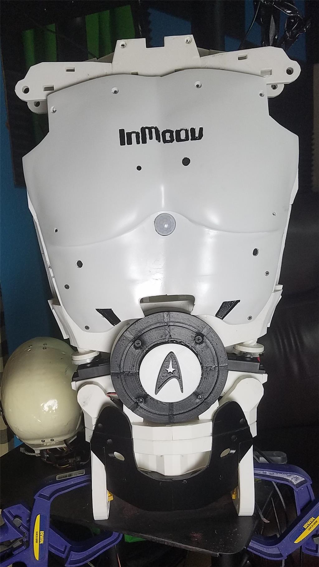


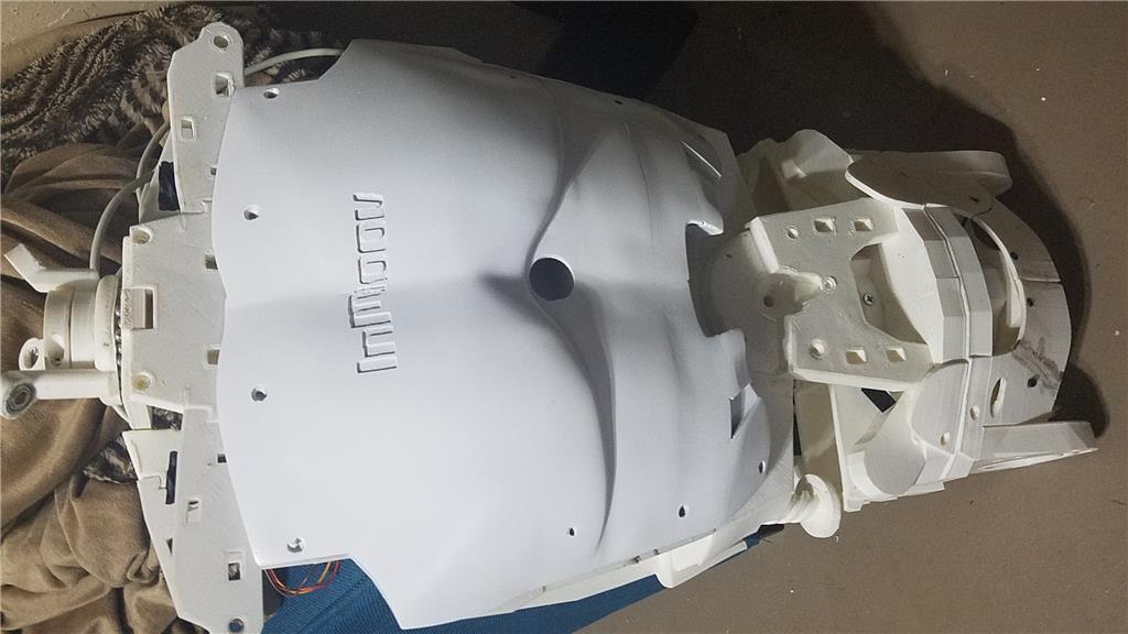
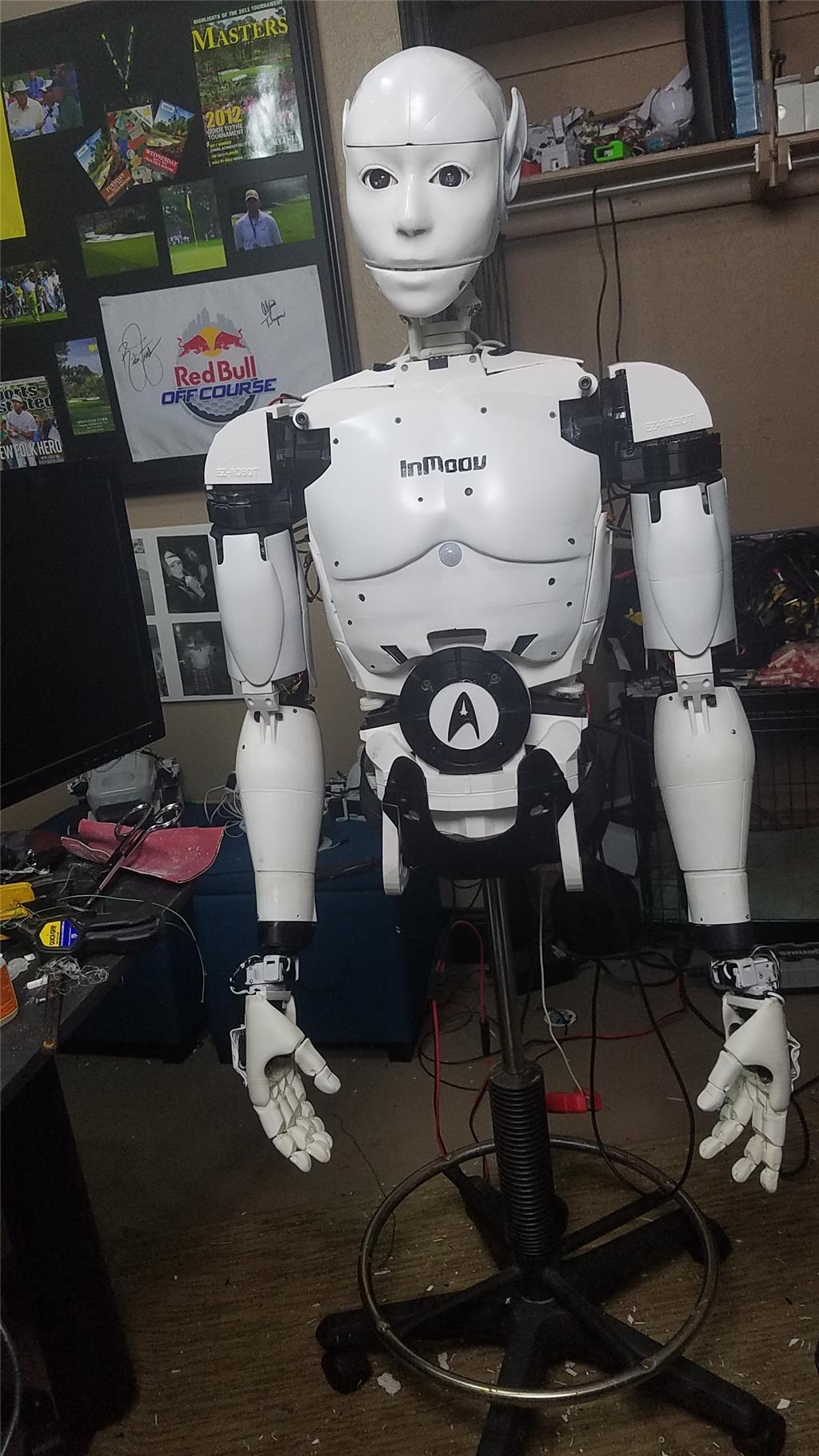
I have decided to start my InMoov project. I think I will call him Spock out of respect to Leonard Nimoy who passed away on the day that I started this project.
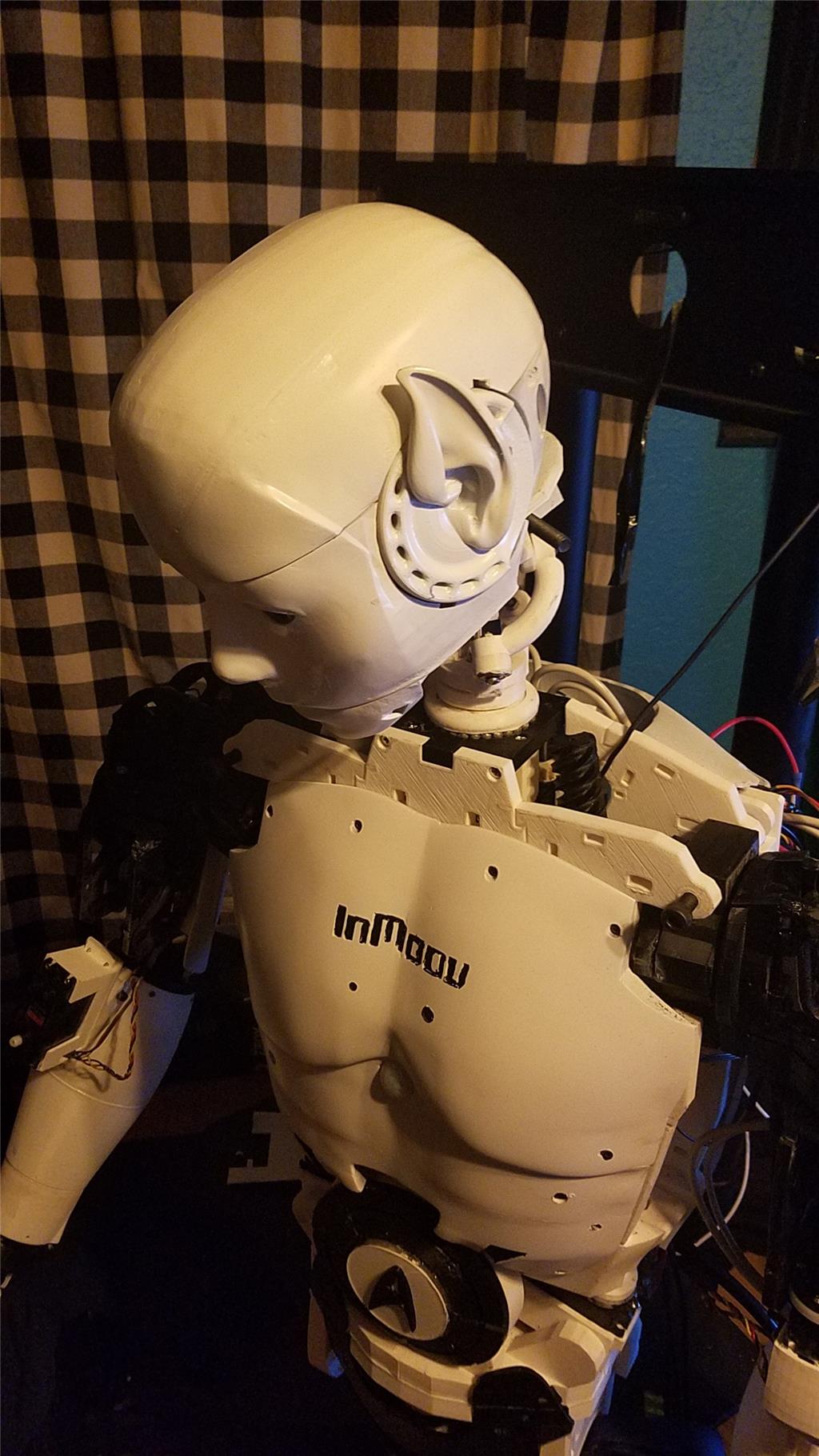
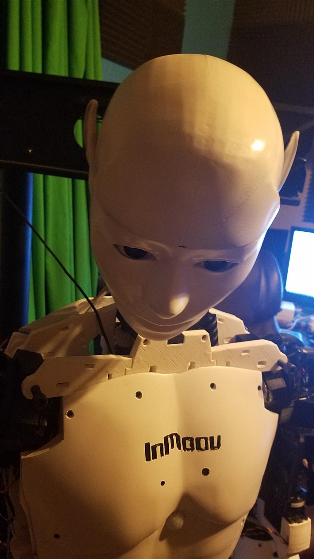
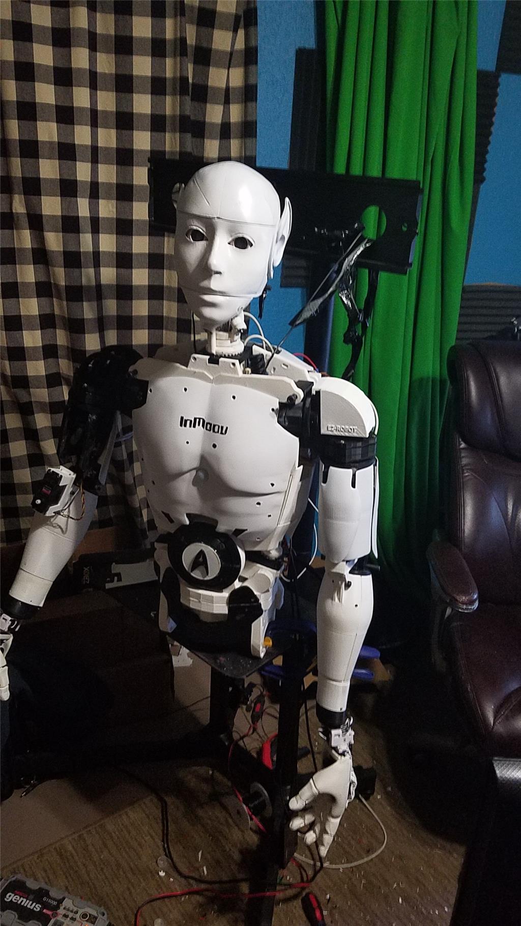
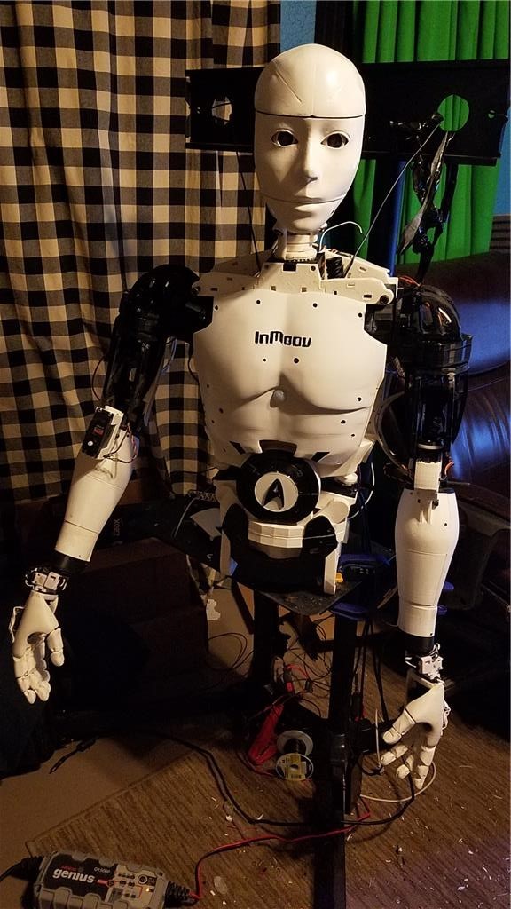
I am editing this post so as not to confuse people with the current configuration. I continue to update this post with the latest photos. If you are reading this for the first time, don't be confused. There have been a lot of changes to the InMoov over the past couple of years including starting over.
https://synthiam.com/Community/Questions/7398&page=21 Post 203 starts the rebuild of the InMoov.
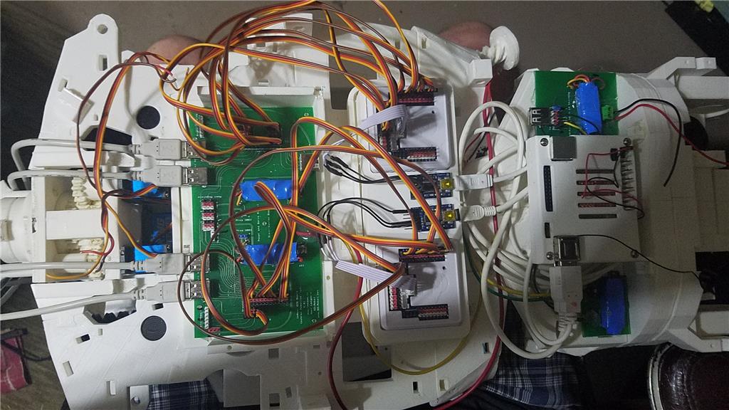
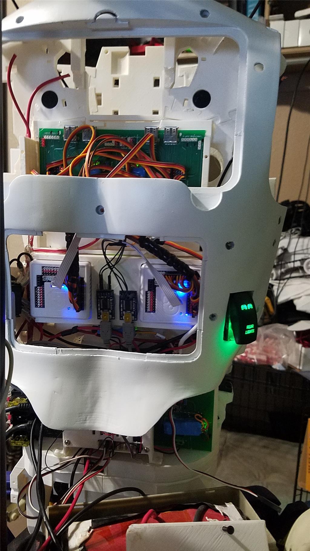
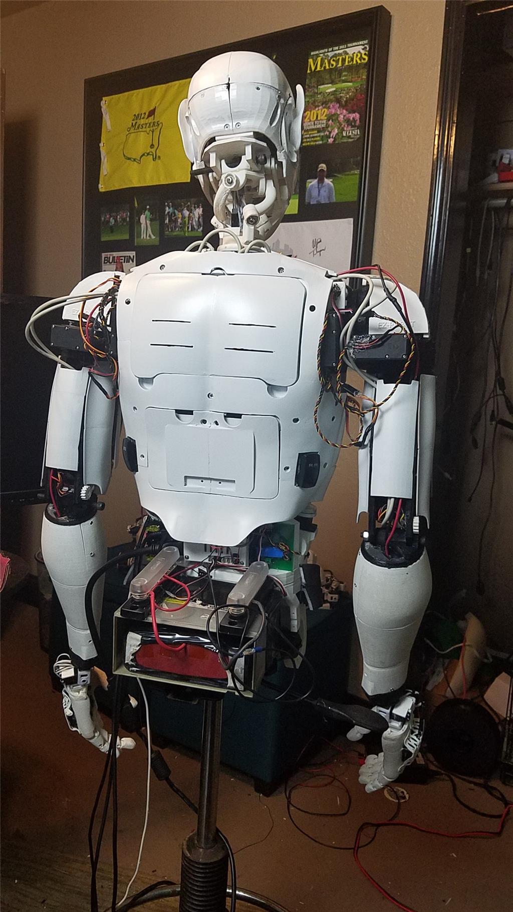
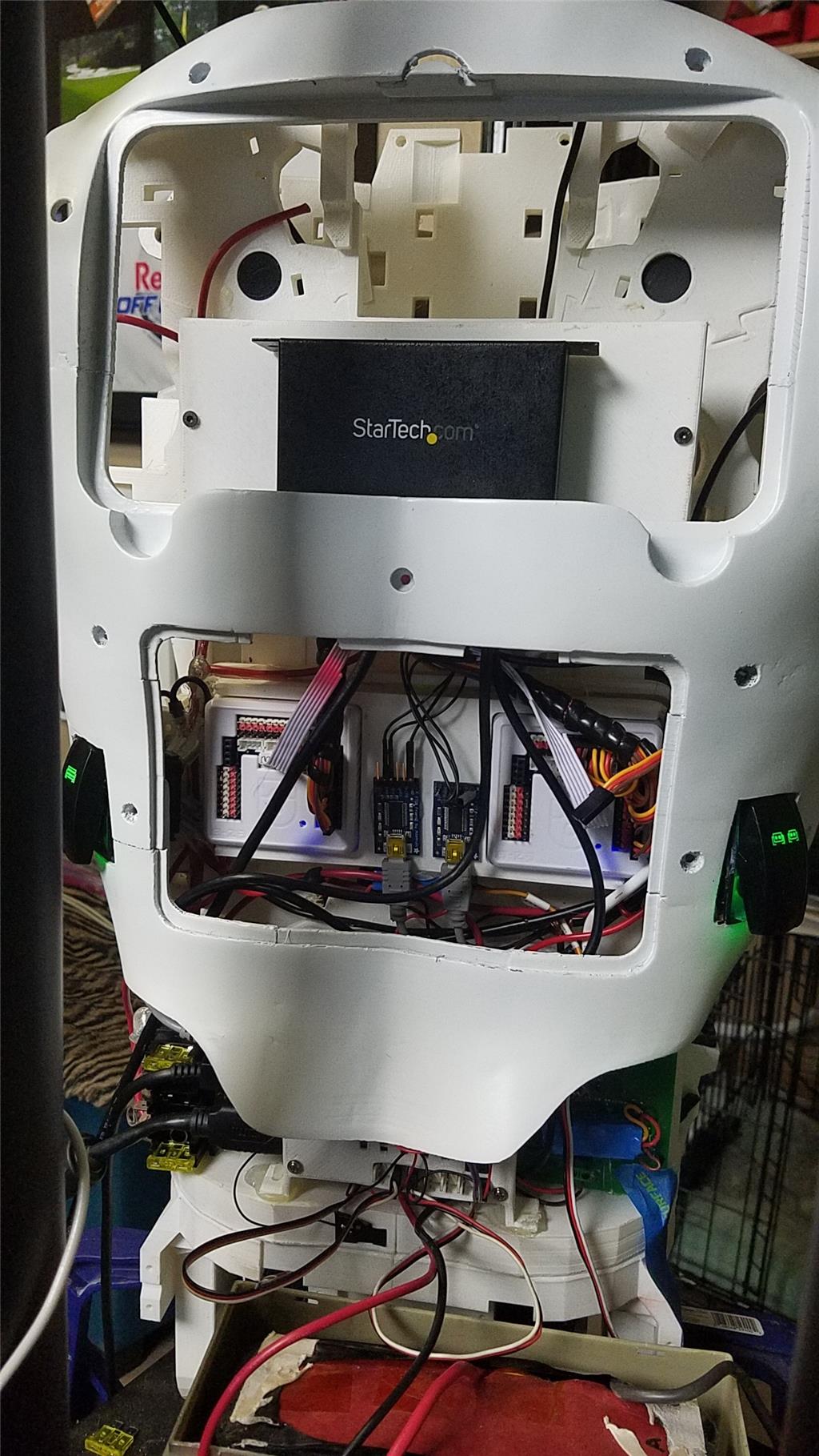
I have decided to use an onboard computer. I chose the Latte Panda due to it having an onboard arduino Leonardo and also because it uses little power.
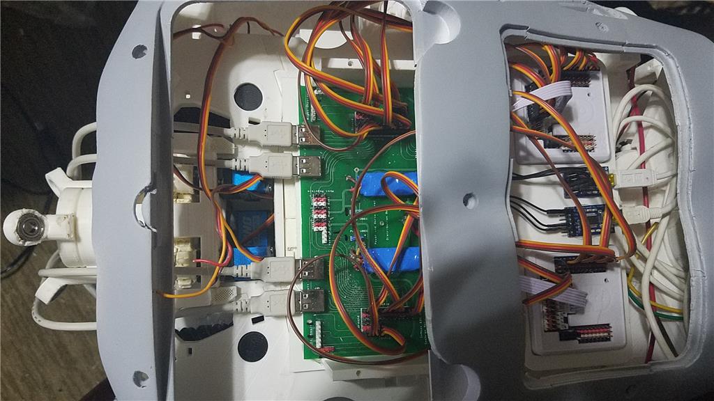
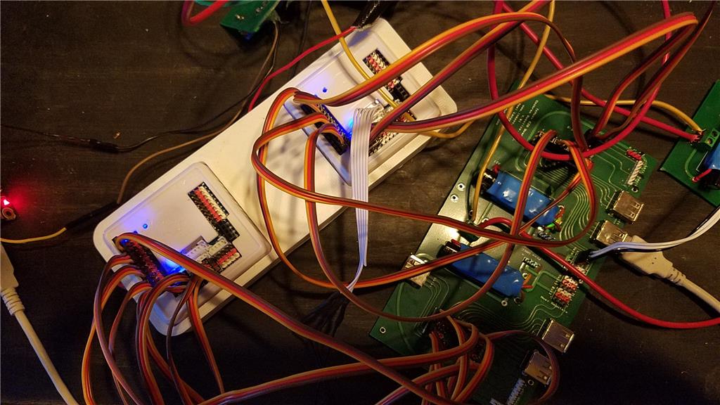
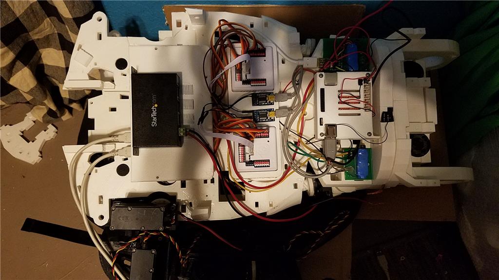
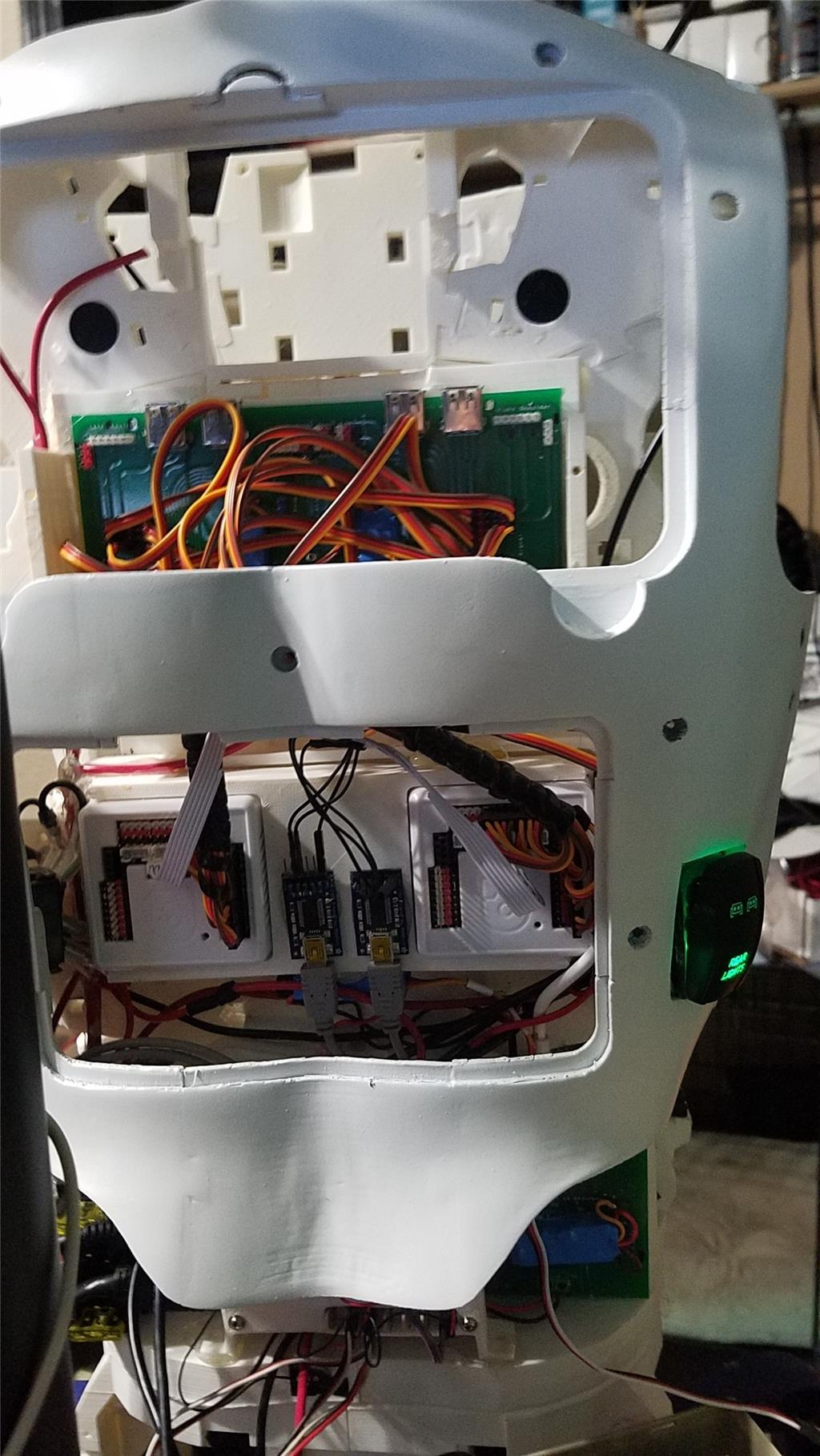
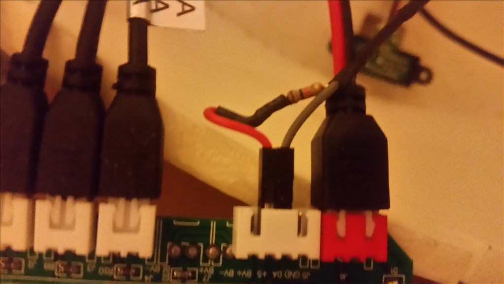
I used 2 EZ-B controllers connected via the camera port to Adafruit FTDI friend boards. This allows the Latte Panda to have a non-wifi dependent connection to the EZ-B's. I use a powered USB hub connected to the USB3 port on the Latte Panda to attach other items.
The Omron HVC-P is used to identify people, emotions, human bodies, hands, age and gender. It is attached to the Latte Panda via an FTDI friend which is then connected to the powered USB hub. It is mounted in the chest of the InMoov. I also use a 3 element microphone which is a MXL AC-404 microphone. It is disassembled and the board and microphone elements are mounted in the chest of the InMoov. This mic board is connected to the Latte Panda via a usb cable which is attached to the powered USB hub. There is a USB camera in the eye of the InMoov which is connected to the Latte Panda via the powered USB hub.
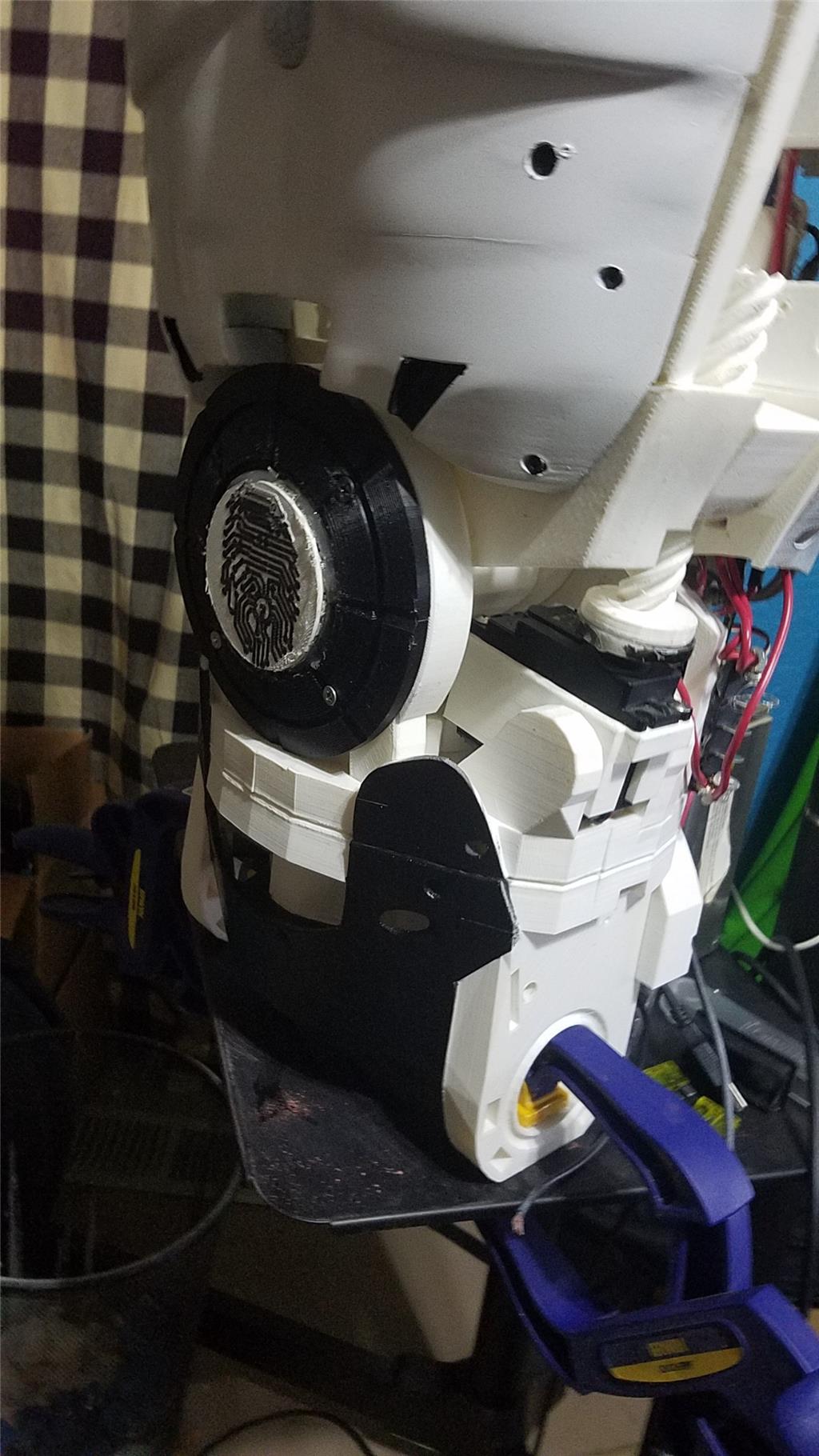
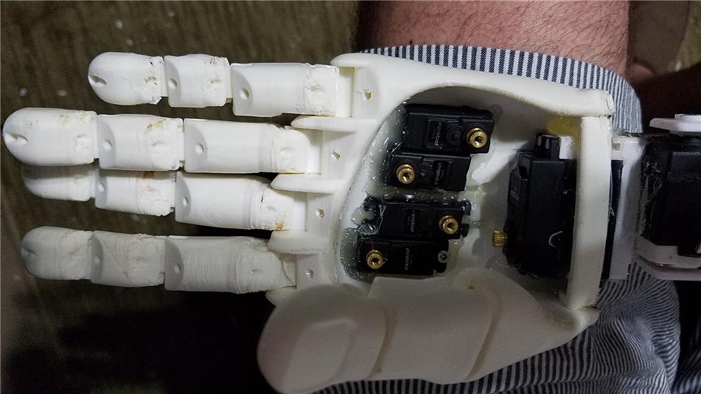
I chose to use the Flexy hand with the InMoov. The design is far more rugged than the original hand and works very well. There are 4 EZ-Robot Micro Servos in the palm of each hand which controls the main fingers. The thumb is controlled by an EZ-Robot HD servo. The wrist waves and uses an EZ-Robot HD servo to do this motion. I use the standard Rotational wrist.
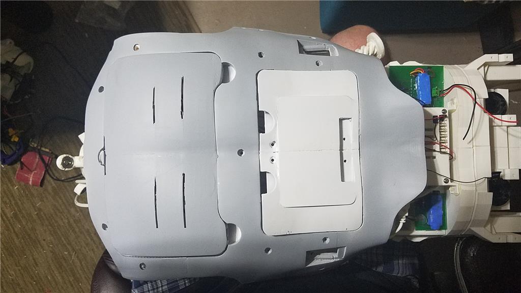
I have castle BEC's for power in the following locations set to the following voltages. Forearm's - 6.2 V - Controls fingers, wrist and elbows Custom power distribution board (2) set to 6.2 V controlling head, neck and Shoulder servos. EZ-B's - set to 6.1 V - it is mounted in the controller mounting plate and connects to the EZ-B fused power boards from a power base. Latte Panda - Set to 5.1 V and is mounted to the EZ-B controller mounting plate. Waist - set to 6.2 V and is mounted in the lower right side of the back. This provides power to the lean and pivot waist motors..
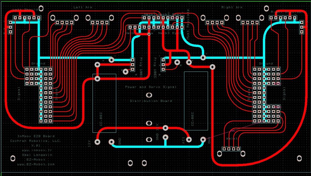
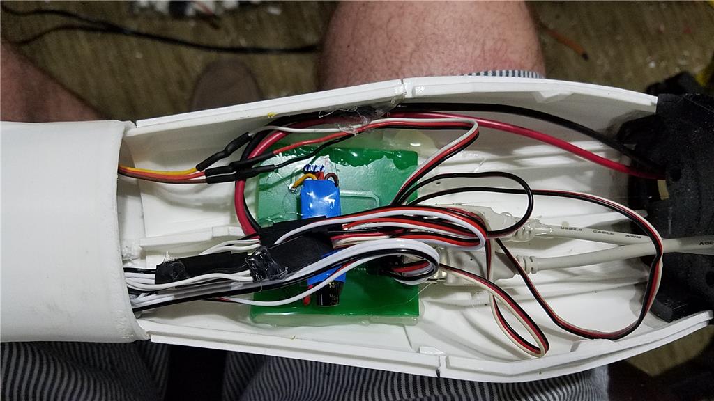
There are some custom power and signal distribution boards. These are in the forearms, lower back and in the upper back. The upper back or main board connects to these distribution points via USB cables to provide signal to the other boards for servos. The main board also has servo connector pins that are for the neck, head and shoulders. This allows the power to be distributed between multiple BEC's and also allows the servo signal cables to be shorter and more protected via the USB cables.
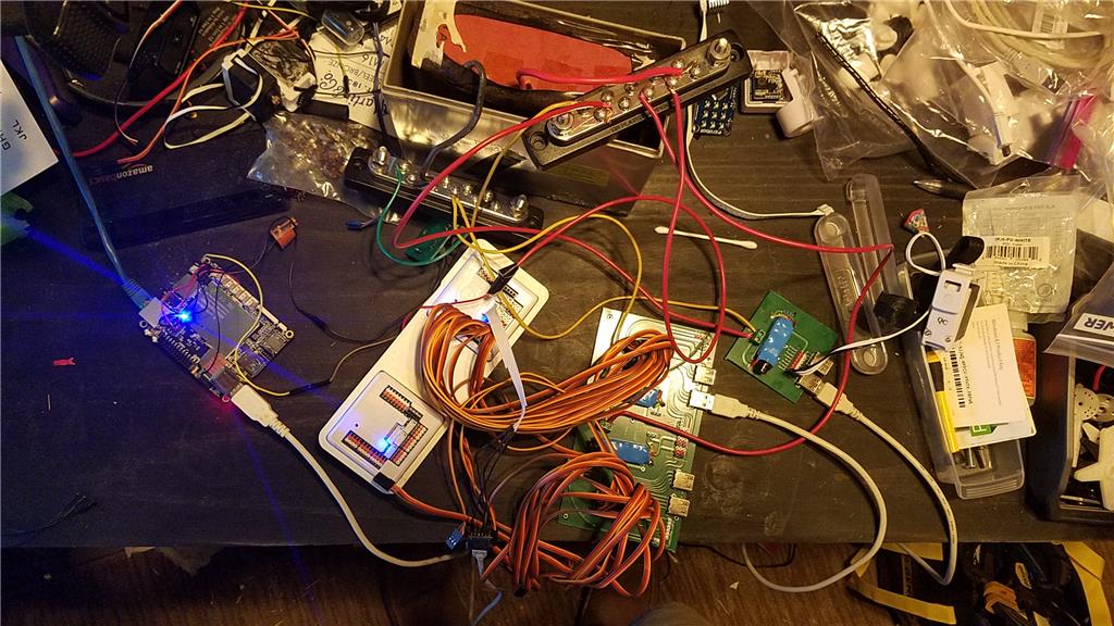
For power I use a LiFePo4 battery that is rated at 30 amps. It has the balanced charging circuit built into the battery and also has a low voltage shutoff built into the battery. This protects the battery and allows the battery to be charged with standard car chargers.
I put switches on the back on the InMoov which are rated at 20 amps at 12 volts. These are rocker switches that allow the user to pretty much slap the switch to turn it off. There are two of these switches. The servos for the elbows and fingers are on one switch. The latte panda, neck, shoulders, EZ-B's, waist motors and some lighting is on the other switch.
I also added a fuse block. This allows 20 amp fuses to be put in line to help protect things. The switches above drive the fuses for each of of the motors listed in that section.
-636348716348649435.jpg)

Discover more robots
Gary's RALPH
Imrisaac's Ez-B Project V3.0

I had thought about using some CAT6 cable but its not something people normally have laying around the house. It is 4 pair twisted. Will try the ferrite toroids on the servo wires off of the distribution board and see how it works out.
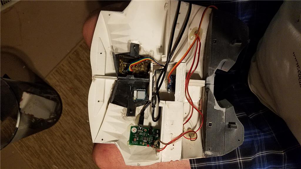
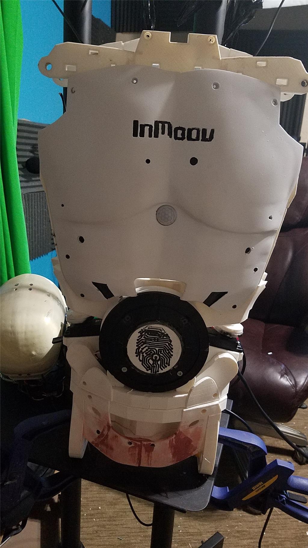
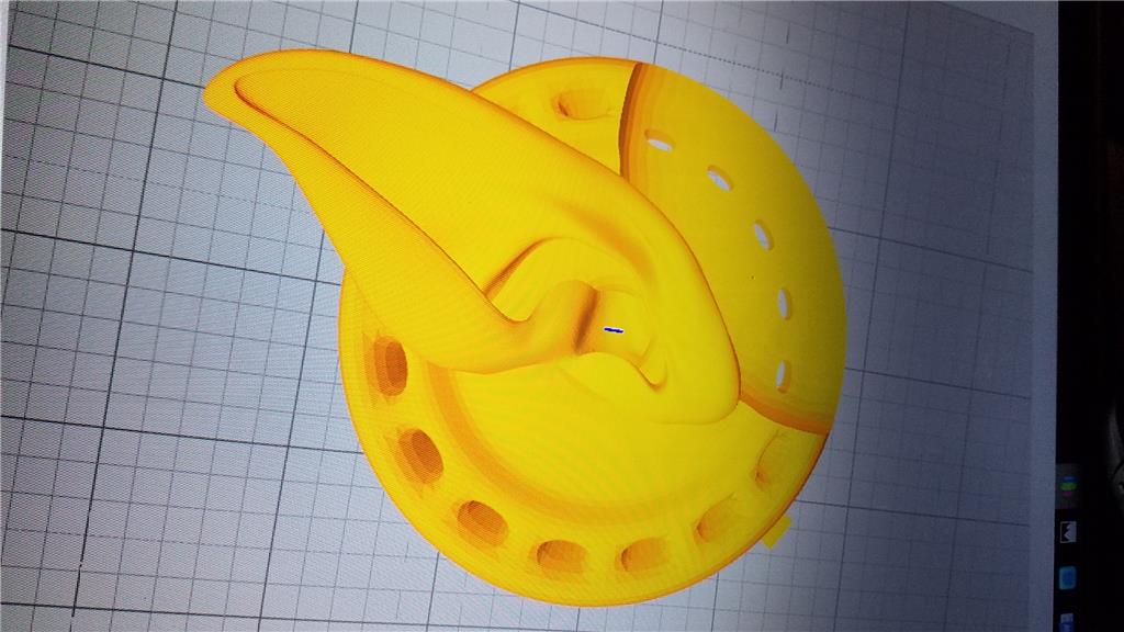
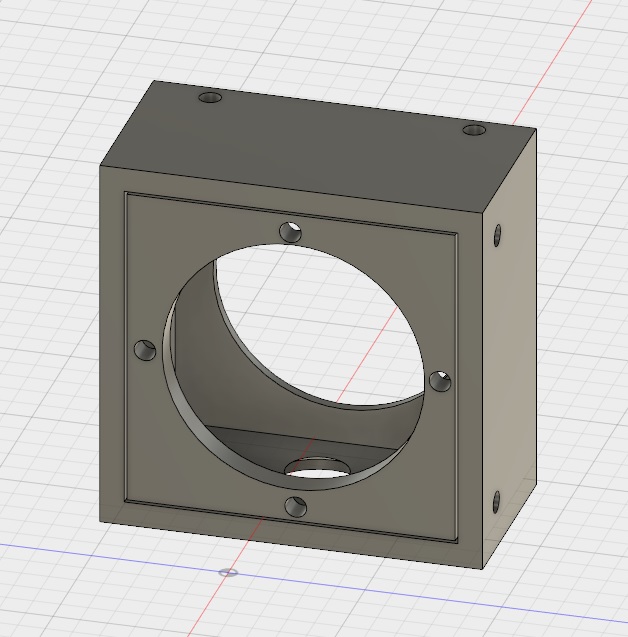
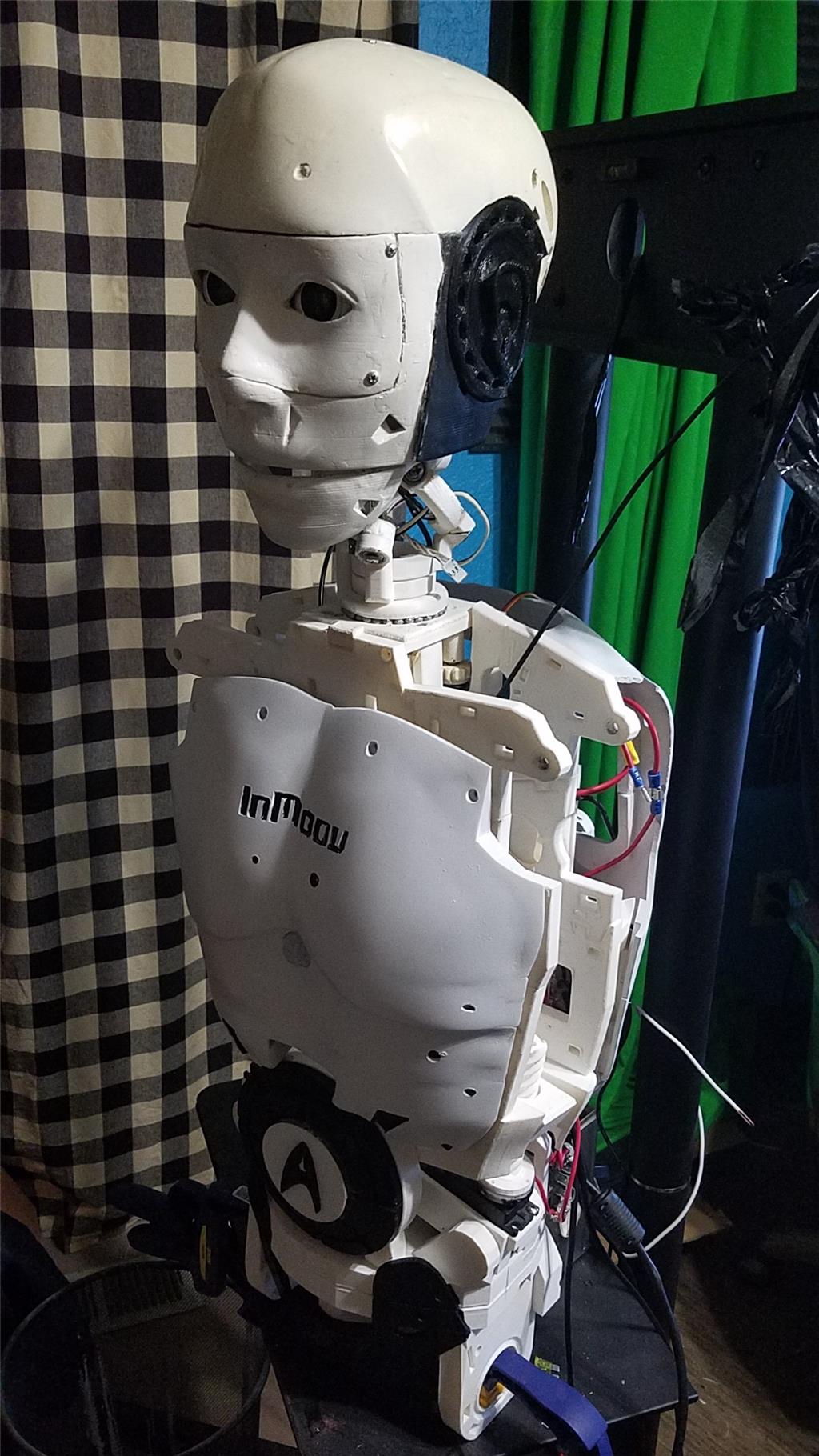
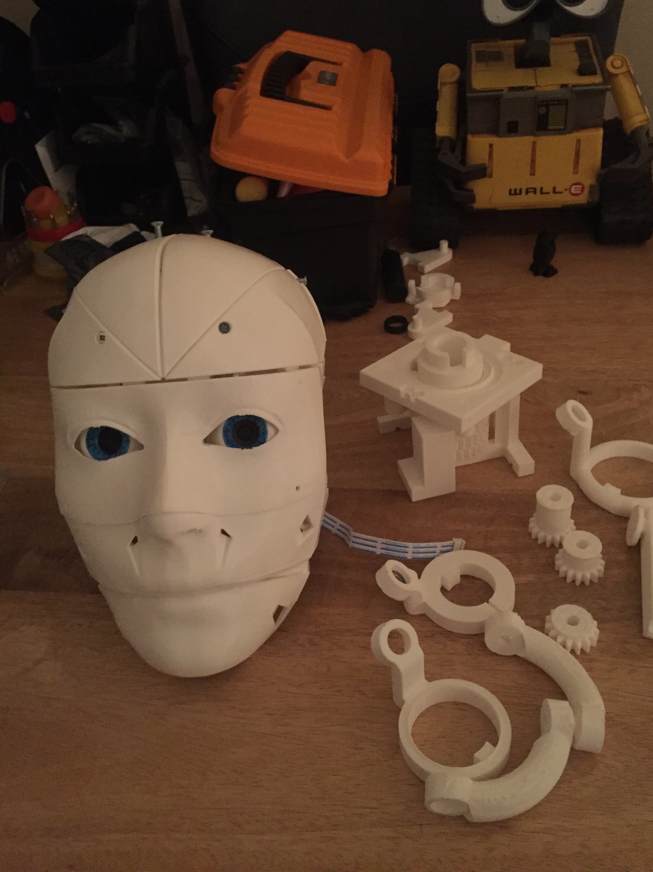
The face is printed and the eyes are attached. Still printing the rest of the head. I am printing at 100 micron layer heights so it is taking a while to print out. It should require less sanding and filling I would think, but we will see. I am going to use a much roomier design in the head that might let me mount the LP inside the head. Removing the large servo from the head helps.
The roomier head has a different jaw design. It places the servo in the middle of the head with the hinge being at the back of the head. The servo is also positioned in the middle of the jaw which should help to have the entire jaw move evenly instead of one side being slightly out of alignment when moving. The servo will have to move more to make the jaw move but the guy who designed this head adjusted the worm gear for the mouth to accommodate this, but I think this looks like a better design than the original. I wont know for sure until everything is built for the head I suppose.
I still have a binding issue in the neck. I think I will have to print smaller gears for the servos in the neck.
The shoulder pots have all been soldered. I should be able to test them out tonight.
I still need to build that stand. I have multiple rolling chairs to use. I just need to pick up a pole.
Good luck with the ferries. Regular twisted servo cable along with the ferries is a good idea also. I was having this same twitching in my B9 arm also. The problem is that running power cables along with the signal cables causes induction into the signal cables. This is because of the magnetic fields they power feed produces. Twisting cables and also wrapping them In opposite directions around ferrite rings, cores (or really anything round) cancels out the magnetic fields. I ran both the twisted cable and ferrite rings and the problem stopped. I also noticed that sometimes by simply moving the cables away from each other helped the issue.
As a last resort you can try to run power cables separately and as far away from signal cables as possible. You really only need one positive and one negative power cable running to a group of servos as long as they are big enough to handle the full load. Then split the feed as close to the servos as possible. This method may help you find space to move the power feed away from the signal cables.
It's a frustrating and unsightly phenomenon for sure. Good luck Dave.
The head should be printed and ready to finish assembly by tomorrow morning. The shoulder tests were about 50% successful. The left arm has 1 servo that I need to get dialed in. The right arm has 2 that I need to get dialed in. Hopefully I will have some time to do that tonight.
The ferrite rings should be in today. I will be able to see if this solves the issue with the elbow or not. I plan on wrapping all 8 servo wires in alternating directions to see if this solves the issue. This is coming off of the power and signal distribution boards that are in the arms.
After the head completes printing, I will print some smaller gears for the neck and see if that solves the binding issue.
And then, there is the stand. Still haven't started on it. It would be nice to finish the stand off because this TV stand takes up a lot of room in my office.
Looks like you're making positive progress. That's what's important. We all know this is not a race, it's a journey.
Just to be clear (I'm sure you're aware but this is for others), each cable should be on it's own ferrite ring for best results. I found this good explanation of positioning the ferrite rings: If it's preventing susceptibility problems due to interference coming down a cable then its position is not that critical. However, if it's stopping emissions getting out from a device, a better position is as close to the interfering source as possible. There is every chance that interference getting onto a cable (such as from a switched mode power converter) can radiate from the cable so, best to keep the ferrite up as close to the source of noise as much as possible. It's possible the interference is coming from those little Castle BIC's your using. Switching power supplies are great but they are noisy.
Your build is exciting to watch. Thanks for sharing this with us.
Thanks Dave,
yea, I have concluded that the interference is between the BEC and the servos. Hopefully wrapping each of the servos in a Ferrite ring will solve the issue. They should be in today so I will have an answer soon enough.
The funny thing is that the issue doesn't appear on the same type of servos running the shoulders, or the one that was in the head. These servos plug into locations that are more spaced out on the main distribution board (which is using BECs also) but are not experiencing the issue. I bought enough rings to wrap each servo. I may go ahead and do that anyway even though these are not showing the problem right now. You know how things creep into the mix when they were working fine earlier.
Thanks for the input. I appreciate it.
The ferrite rings solved the issue with the elbow on one arm. I haven't installed them in the other arm yet. Thanks Dave for the advice. It was an easy fix to a frustrating issue.
The head is assembled except for the jaw. I should have it printed tomorrow. I have the pinion gears printing at 97% now for the neck. They should be finished in a couple of hours and I should be able to know if that is the right direction to go in to solve the neck binding issue.
Left arm and shoulder all working.
Next is the right arm. There are 2 pots that I need to look at in the shoulder and then the elbow pot adjustment and it should be done. I decided to keep the Latte Panda at the bottom of the back. This lets the arduino section still make short runs to the neopixels in the stomach.
The reprint of the pinion gears for the neck was pretty sloppy. I will reprint them after I finish the jaw tomorrow.
The neck is quickly becoming the section that I need to get figured out. Without it, I can't mount the head. The pinion gears may be printed before the jaw. Will see how busy I am tomorrow which will decide what gets printed next.
@Dave, I'm thrilled that the rings worked for you. Victories like this are great and help fual the ambition.