Homemade Biped Robot

jeffmorris

USA

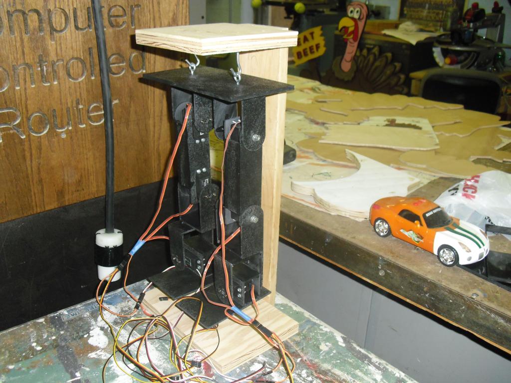
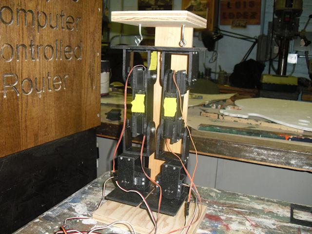
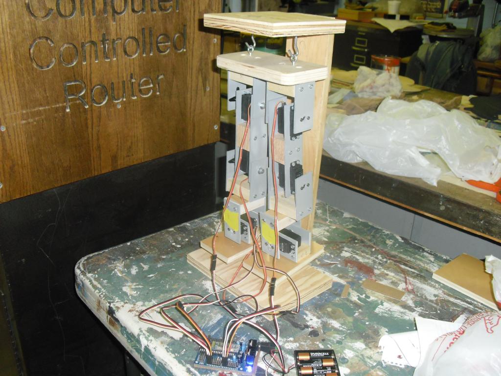
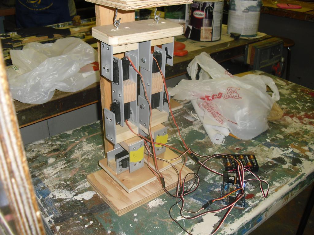
I built a biped robot but I found out that the servos that came with the EZ-Robot kit are not strong enough. The hip servos can't lift the legs up. Any suggestions for stronger servos?

User-inserted image

User-inserted image

By — Last update

ARC Pro

Upgrade to ARC Pro

ARC Pro is your passport to a world of endless possibilities in robot programming, waiting for you to explore.

Ecuador
#1  

Amazing! your brackets for the biped are incredible ! :)

PRO
Synthiam
#2  

Hey Jeff, that's really neat! You will need stronger servos for sure. I'm not certain what weight your assembly is... Are the brackets metal? You may consider making the brackets out of 2.5mm thick styrene or pexi glass/acrylic... A small digital weight scale will help you determine the difference between the materials.

As for the servos, we have heavy duty servos in our store - that have a strong lift. :)

#3  

Yes plexiglass is very light but plenty strong. Djs servos are pretty strong but you need to weight your robot to know what torque servos you need for sure. Also remember jeff high torque servos need a alternate powerv supply..

#4  

HI Jeff, Very Cool Biped Project ! My tronger servos suggestion for your project ;

Futaba, S3306 High-Torque 1/5 Scale ( analog )

Volts ;4.8V

Torque ;267 oz-in (19.2 kg/cm)

Speed ;0.20 sec/60

Volts ; 6.0V

Torque ; 333 oz-in. (24.0 kg/cm)

Speed ; 0.16 sec/60

Dimensions ;2-5/8 x 1-3/16 x 2-1/4 in (66 x 30 x 57 mm)

Weight ; 4-7/16 oz (126 g)

Or if you need regular size check this site ; http://www.futaba-rc.com/servos/analog.html

Thanks Michel

Canada
#5  

Hello Jeff... wow, very nice! I love the bench test hanger idea. Look forward to seeing more action shots once it gets it's hip replacement :)

Did you use the continuous rotation servos for the feet?

#6  

That servo is a 1/5 scale very large servo and 50 bucks each for a Analog. Either get djs futuba 160 oz in servos in the store for like 13 dollars or if you need more power pololu.com had power hd 1501mg which is 20 dollars but 240 oz in torque. Both of these servos are standard size therefore compact and are great performance for the money. :)

#7  

If you are ok with spending the extra 7 dollars a servo for 240 oz in (which with your setup I recommend because it weights more) then here is the next step up from djs high torque servo

http://www.pololu.com/catalog/product/1057 User-inserted image

I love djs equipment but I also want you to have a right fit of equipment to your frame. Pull the servos off that come with the kit and keep them for your next project . Afterall they are great servos :)

#8  

Michael, I need standard-size servos. Gunner, I didn't use the continuous rotation servos. I used two extra servos that came from BASIC Stamp kit. I found out that HobbyPartz store has cheaper prices on servos but I'm not sure if their servos are good or junk.

#9  

I found out that my homemade biped robot weighs about 2-1/2 pounds.

#10  

I started building a new version of my homemade biped robot out of 1/4" ABS (I think) plastic only. I cut out the parts on my CNC router.

#11  

User-inserted image

User-inserted image

New version of my homemade biped robot. The servos that came with the EZ-Robot kit aren't powerful enough. I had to order 240 in-oz servos from Pololu website.

http://www.pololu.com/catalog/product/1057

PRO
Synthiam
#12  

Whoa that is a nice biped frame. Great work, i'm impressed. Did you CAD the items yourself?

The heavy duty servos may need an alternate power source. The Voltage Regulator on the EZ-B may not be enough. If your battery source is no greater than 6volts, then you can power those servos with direct battery power. To do this, simply take 3 wire peripherals cables and keep the White and Black wire (signal and gnd), but cut the RED at the female plug. Connect the RED wire to the 6v battery source directly :)

For batteries, i would recommend a light weight LIPO with high amps.

User-inserted image

#13  

Doesn't the ground need to be spliced and also go to the ground on the battery? This way all that current is not grounding to the ezb?

PRO
Synthiam
#15  

You need a common GND, so might as well use the GND from the EZ-B. You can splice in the GND also, like my example with the +5, but it's just more work.

#16  

I used AutoCAD to draw the parts, used Cut2D to create code for my CNC router, and used Mach3Mill to cut out the parts on my CNC router. The EZ-Board V3 should have a jumper that lets me use separate power source for servos.

DJ Sures, I don't like the way the forum is set up. The messages are not in date/time order.

PRO
Synthiam
#17  

@JeffMorris, we originally looked at using a jumper for alternate power source, as you can see the space on the board for it is labelled "EXT PWR SEL". However, those jumpers are only rated for 1 amp, and had huge resistance. The jumper was removed. You can provide alternate power by modifying the EZ-B and cutting the EXT PWR SEL trace on the bottom of the PCB.

By cutting the trace, the pins D0-D14 are seperated from the EZ-B's internal VR. Power can be applied to the top 2 pins (above D14) labelled EXT PWR

The forum is configured to display messages in Date/Time order. Original message is first, and every message is added to it - so the last message on the last page is the most recent post. It's the default way for all forums.

You may be able to add a fan to the EZ-B's internal VR heatsink - as i usually do and many others on here. A small 3cm fan works great. Here is a photo of how I usually do it. Keep in mind, the VR on the LEFT of the PCB (closest to the power connector) is the VR you wish to cool the most. I power 12 servos in a biped and hexapod using a small 5volt 3cm fan.

User-inserted image

User-inserted image

Good work with your project!

Canada
#18  

@jeffmorris if you are handy with a soldering iron you could both cut the trace and install a jumper option for your own use... (Do so at your own risk!... probably voids what warranty there may be :)). I modded my board this way and it works great User-inserted image User-inserted image But as DJ said, when using on-board regulator (with jumper installed) you may run into amperage/resistance issues depending on the quality of your soldering, the jumper pins and the jumper itself. That said, if you are running that much amperage then you probably want the jumper off and using external power anyhow:) I just like the convenience of the jumper for my purposes... less cable splicing :P

Oh yes... be aware it is a double sided board and you might need to solder both sides. The tricky one is on the top side (right under where the jumper goes... :P)

#19  

I think that I ruined the EZ-Board by cutting the trace. If a servo is connected to D0 port, nothing happens. Servos connected to D1 and up ports work. How can I fix it?

#20  

Thats weird. If one ports power is working I imagine they all would this is why im not keen on modifying the board when the power can be provided externally. I hope its not messed up.

Canada
#21  

With the EZ-B unplugged from power try testing continuity between ports D0-D14 5v line (the middle one) and the EXT PWR pin. Then D15-D19 and the 5v pin over by the ADC ports. Then make sure there is no conductivity between both sets of ports (D0-D14) & (D15-D19). If anything, I had trouble making the cut clean as it sometimes allowed a small current through, something you don't want with two power sources feeding from each end. Hope this makes sense... just a quick post from work :)

Canada
#22  

Hello Jeff, any further info on the issue you had?

After cutting the trace were you running D0-D14 off of EXT PWR when you noticed that D0 was not working?

Can you show any close photos of the cut you made?

And any other details you can provide will help us troubleshoot what may have happened.

#23  

I accidentally cut the trace for D0 and another trace at the edge of the board. I think I ruined the board trying to solder a piece of solid wire to the D0 trace. Is it possible for me to exchange the board for another one?

Canada
#24  

Oh, sorry to hear that. There is always an inherent risk of damage when we as hobbyists attempt to expand and modify our toys :)

As far as purchasing replacement parts or other options, I would suggest you take up that discussion with the staff (I am just a fellow client and hobbyist myself). DJ might weigh in on this topic or you can try this link to their contact page CONTACT

Don't Panic:) everything is usually repairable or salvageable... and sometimes that is a required part in our learning process with these techie hobbies and ventures.

#25  

Nope:( modification of the boards at your own risk. That sucks man. I could buy it off of you for parts or work out trade for nice servos.

#26  

I soldered another piece of solid wire to the other trace and the board appeared to work except for D0 where I broke the copper trace trying solder solid wire to D0 trace. Is it possible to drill holes on both sides of the broken D0 trace and solder new piece of solid wire in the holes?

Canada
#27  

@jeffmorris Glad to hear that it was only MOSTLY dead:D However I would NOT recommend drilling any holes!... it is a double-sided board and you do not know what trace you could damage on the other side!

Do you know what that trace was for? You have three choices on the pin it was leading too: Ground (innermost), Power (center) or Signal (outermost). If it was ground or power then, as I understand it, only the signal is controlled directly by the PIC. Power and ground are shared with all other ports. Thus I believe you can simply tie into the next port over by making a solder bridge (on the back side of the board) between matching pins for D0 & D1. If anyone knows of an error in this then please chime in as it is a learning point for all :)

If it was the signal, then you might be better off calling that port a goner and ignoring it.

Canada
#28  

Also, if possible show us a close picture of the trace area so we (I :P) am not totally guessing what you mean :)

#29  

I ruined the D0 signal trace. I had to call it a goner unless I can solder a jumper wire from D0 signal pin to PIC pin. Which PIC pin is for D0 signal pin?

Canada
#30  

That is a DJ-Sures question:) Might be doable or add to other issues... but if you do that, make sure you remove the PIC first to avoid thermal damage to it.

#31  

After creating a program in ARC software to run a modified servo on D0 port, I took a piece of jumper wire and checked which PIC pin controls D0 port. I soldered the jumper wire between D0 pin and a PIC pin. I think I finally fixed my EZ-Board.

Canada
#32  

Very logical thinking:) Way to go!

#33  

I got six servos that have torque rating of 240 oz-in and they can lift the legs.

#34  

I built the robot that is similar to Lynxmotion BRAT robot. I think the robot is too heavy beacuse the ankle servos can't tilt the robot to one side so that the leg that's not touching the ground can move to another position. Any suggestions?

PRO
Synthiam
#35  

Jeff, I built a Hexapod and biped using styrene. It's a light weight plastic material you can find at hobby shops or online. It can be cut with laser cutter or Cnc. I just use a razor knife and a ruler. There are many dowels and construction peices to help assemble the sheets (square dowels etc)

I used to use the styrene cement. Now I just use a hot glue gun :)

It might be a lighter solution for you. Most of the lynx motion kits that I've Experinced are too heavy for even the servos they include :P

#36  

Jeff cheapest places I know that carry styrene are sign and graphics stores. They buy in serious bulk and cut signage out of big sheets. If your nice to them they might even give you scrap for free to use.

#37  

I built a new version of the robot from 1/8" plastic sheet and it appeared to work better but I have to replace one part with 1/4" plastic. I tried a hot glue gun but it made mess on the work table.

Canada
#38  

Glue guns can get a bit dribbly:) I have a DIY stand with a small square of tile that the gun tip rests on. No more table mess or concerns of burning where the tip rests. Next up is a light dimmer addition so I can vary the temp as required so that the glue won't be too hot and melt delicate materials.

Any pics of your new version?

#39  

If you need more of these hi torque servos, I found a better price for them on ebay. Free shipping too. Hope you get him walking soon. My EZ Robot board has been running 1/4 scale servos with no problems. I may give the servos their own power source just to be safe. High Torque Servos

#40  

User-inserted image

The robot still doesn't walk well. Is it possible for a biped robot to walk the same way that a person walk?

#41  

Here is one video example of robotic walking. It's similar to the Robosapien V2 by WowWee.

http://blog.makezine.com/2011/10/20/how-to-three-servos-walking-robot-video/

Not really the same as a human gait, you would need a lot more servos and a gyro for balance.

#42  

I put "roller skate" wheels on the biped robot. How do I have the wheels turn in one direction only? The wheels are not connected to motors. The wheels came from Lego Technics building sets.

Canada
#43  

@jeffmorris If you are using LEGO wheels, then you could add a gear alongside the wheel and try a trick I used with a mini tank that ran on a single motor, to reverse turn I installed a small lever that was positioned just right to slide over some gear teeth when rotating one way, but jammed the gear to a stop when rotating the other way. (A differential allowed the one motor to run both treads even if one was "jammed").

You could also try the same with just the wheel and a angled and/or sliding locking cog, similar to the pull string lock on a set of blinds

PRO
Synthiam
#44  

@Robot-Doc you technically only need a gyro/accelerometer to know when you've fallen over, unless you are building a super duper advanced robot for walking up hills and such.

The biped's i build simply move into pre-programmed positions using the Auto Position control. You can learn more in this video here :)

#45  

This video helps you get your robot doing very cool things easy. Just watch the video and try to do what DJ is doing. Once you know how AutoPosition works you will be able to "program" cool useful moves that you can "run" with voice commands. Like say kick and your robot kicks. I can say hello and my robot says hello and waves. Lots of fun once you know how to do it. Once you teach your robot to walk forward, turn left and turn right you will be able to have your robot chase a red ball. EZ robot software does so much to make your robot do what you want.