
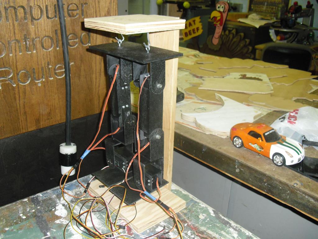
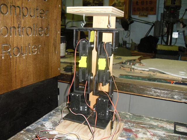
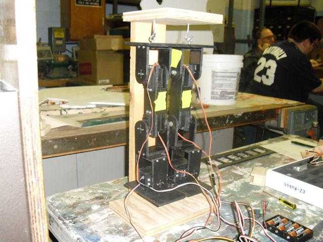
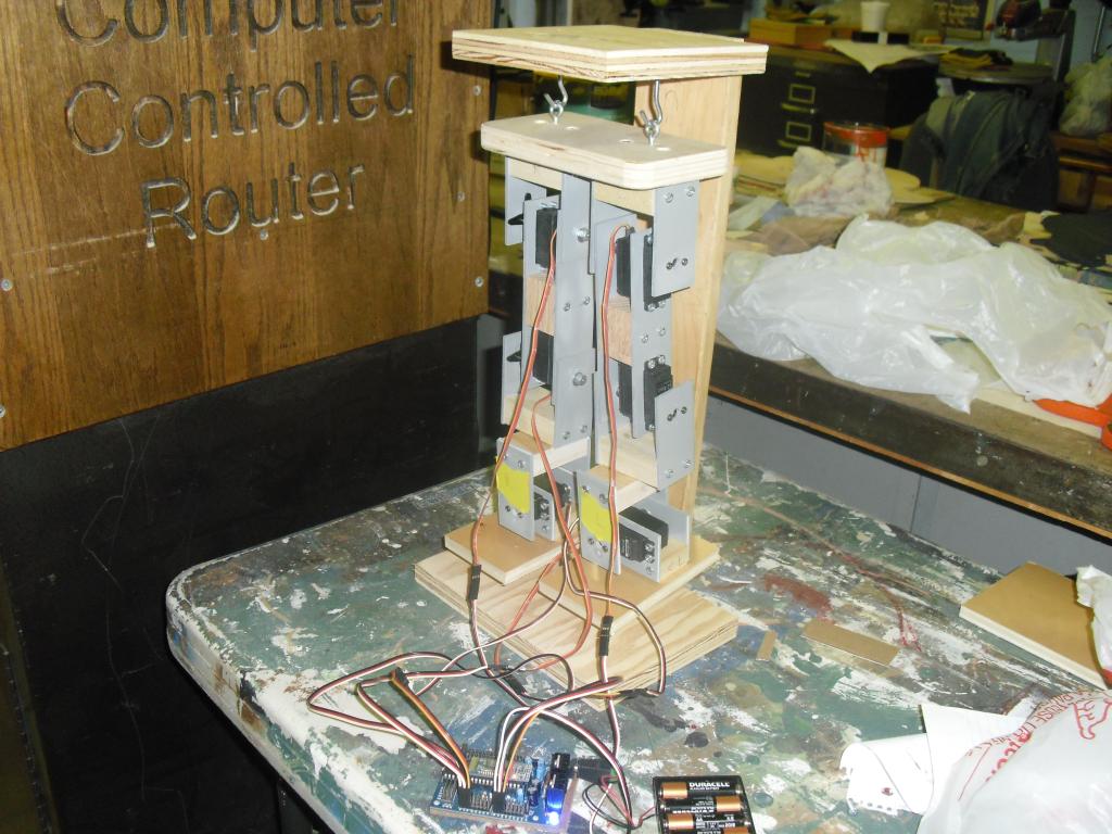
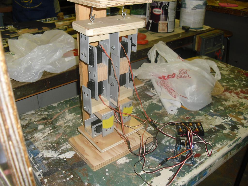
I built a biped robot but I found out that the servos that came with the EZ-Robot kit are not strong enough. The hip servos can't lift the legs up. Any suggestions for stronger servos?
By jeffmorris
— Last update
Discover more robots

Bhouston's Bob's Inmoov
InMoov robot running on EZ-Robot: project recaps, links to original builds and ongoing updates
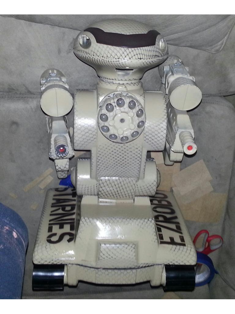
Jstarne1's Rad 2.0 Mech Warrior #3 Air Soft And Nerf...
Trio of outdoor FPV robots with EZ-Robot wireless cameras, each equipped with airsoft automatic guns and a dart...
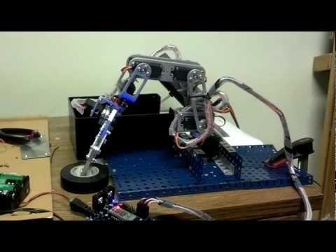
Jphillipsnj's 6 Servo Arm Using Vb.Net, Visual Studio 2010...
Control EZ-B servos with VB: set positions, speeds, timed sequences and releases for wrist, shoulder, elbow and jaw.

Nope modification of the boards at your own risk. That sucks man. I could buy it off of you for parts or work out trade for nice servos.
I soldered another piece of solid wire to the other trace and the board appeared to work except for D0 where I broke the copper trace trying solder solid wire to D0 trace. Is it possible to drill holes on both sides of the broken D0 trace and solder new piece of solid wire in the holes?
@jeffmorris Glad to hear that it was only MOSTLY dead However I would NOT recommend drilling any holes!... it is a double-sided board and you do not know what trace you could damage on the other side!
Do you know what that trace was for? You have three choices on the pin it was leading too: Ground (innermost), Power (center) or Signal (outermost). If it was ground or power then, as I understand it, only the signal is controlled directly by the PIC. Power and ground are shared with all other ports. Thus I believe you can simply tie into the next port over by making a solder bridge (on the back side of the board) between matching pins for D0 & D1. If anyone knows of an error in this then please chime in as it is a learning point for all
If it was the signal, then you might be better off calling that port a goner and ignoring it.
Also, if possible show us a close picture of the trace area so we (I ) am not totally guessing what you mean
I ruined the D0 signal trace. I had to call it a goner unless I can solder a jumper wire from D0 signal pin to PIC pin. Which PIC pin is for D0 signal pin?
That is a DJ-Sures question Might be doable or add to other issues... but if you do that, make sure you remove the PIC first to avoid thermal damage to it.
After creating a program in ARC software to run a modified servo on D0 port, I took a piece of jumper wire and checked which PIC pin controls D0 port. I soldered the jumper wire between D0 pin and a PIC pin. I think I finally fixed my EZ-Board.
Very logical thinking Way to go!