HAL THE ROBOT THAT WALKS AND TALKS

cliffordkoperski

USA
robot video thumbnail

User-inserted image User-inserted image User-inserted image

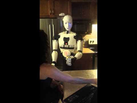
5.5 foot tall humanoid robot that walks and talks. 
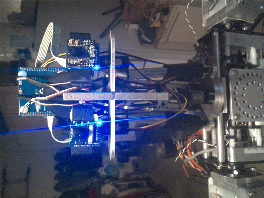
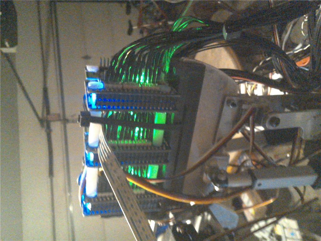
56 servos controlled by 3 ezbv4 boards working together over wifi. On board power supply lasts 1-2.5 hours depending on activity: 7.4v 5a lithium battery for logic and smaller servos and 11.1v 10.5a battery for everything else. DOFs? all of them:) Been out of the ez-robot loop for awhile, and I have to say I like were things are going with synthiam. Plan on taking full advantage of having an onboard pc, and will be converting to arduino in near future. Very interested in bipedal gyro control and scripting if anyone has advise on the matter.

here is a link to my project design on grabcad: https://grabcad.com/library/hal-the-robot-1

By — Last update

ARC Pro

Upgrade to ARC Pro

Experience the transformation – subscribe to Synthiam ARC Pro and watch your robot evolve into a marvel of innovation and intelligence.

PRO
USA
#1  

very good, nice work

#2  

@cliffordkoperski  Very impressive, I was checking out Grabcad.com, I am sure there will be lots of questions, from the members,  and yes Hal's walking would benefit from gyro control. but making first steps is still very good.  more information about Hal's hand design would be my first questions.

#3  

Very cool robot. If you get some of the SSC-32 boards you can control 32 servos from each board using ARC. My robot Dave is much shorter and I never got him walking yet. I may need to build one about the same size as yours next.

United Kingdom
#4  

Very impressive, and the linear actuators make the moments a lot smoother and quicker than standard Servos. Must of been expensive!! :)

#5  

Wow very cool bot,reminds me of the Terminator the way you got the legs! Hands are nice too and I know how complicated the walking can be with balance so congrats!:D

PRO
Canada
#6  

All I can say is WOW! This is one of the most ambitious projects I've seen in a while! Thanks for sharing HAL with us, I will definitely be following this thread for any updates.

I'm very interested in the back story of your creation, I see you had a thread back in 2016 about the arms, you must have been working on this project for quite some time. @Cliffordkoperski if you have some spare time please share the story of HAL with us.

#7  

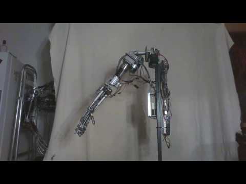
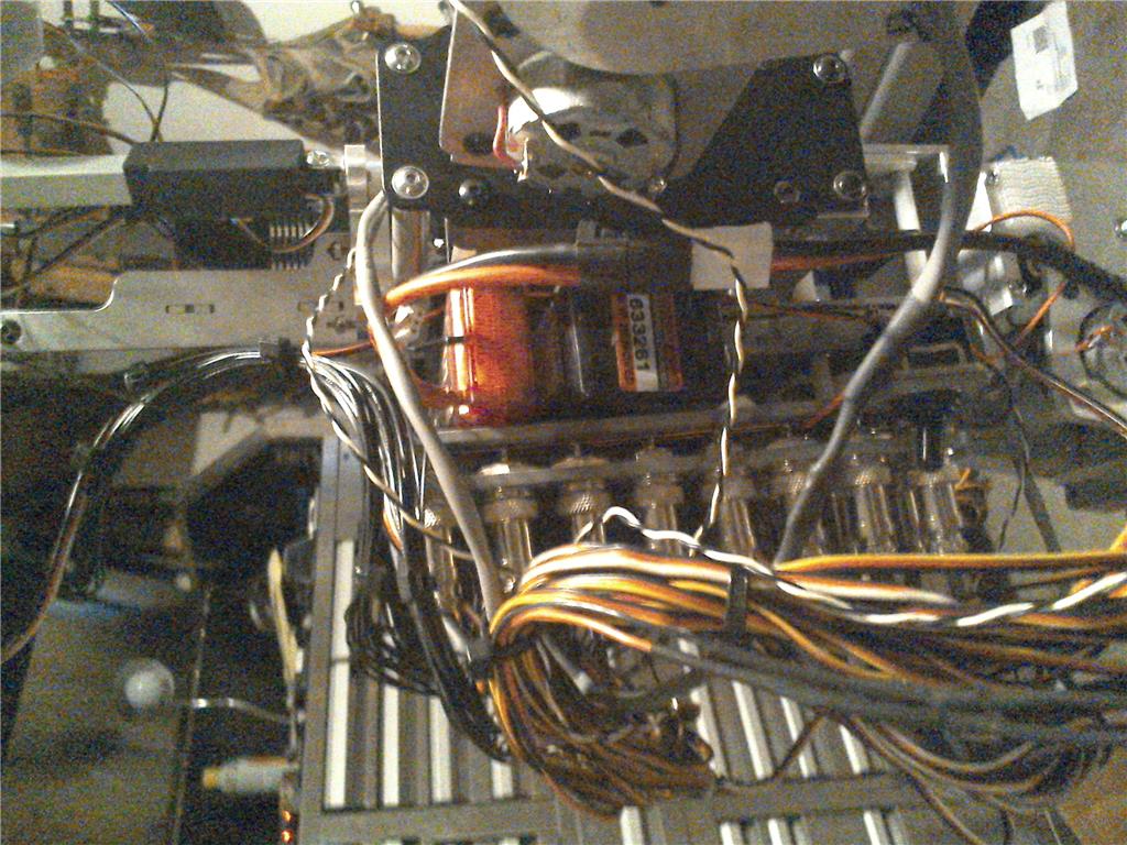
Thanks for the positive feed back!  The back story on this project started with some R&D work on producing a robust human proof industrial robot design, resulting in the 2016 thread on a arm controlled by hydraulics. The hydraulic concept proved messy, expensive, and overly complicated. Ironically about a month after scraping the project I found an article published by NASA back in the 60's on how they designed an entire human sized hydraulic robot which failed for the same reasons, wish I read that before hand. So in 2017 I decided to go electric, I bought some dc motors with a built in worm gear reduction box, and converted them in to servos using pots and syren50 control boards from dimension engineering. I also found detailed machining blue prints for making the hollywood terminator hand and forearm so I custom machined that out of 303 stainless steel and came up with this youtube video posted bellow.

Electric was definitely the way to go, but  if I were to build an entire body with these motors the damn machine would weigh over 500 pounds. So I scratched my head till 2018, then decided to build "HAL" out of cnc machined 6061 1/8 inch extruded aluminum plate, and use hobby grade servos and actuators bringing the build weight to a little over 85 pounds. The HAL design is not as robust as I would like yet but the original goal is a few tweeks away. I believe the HAL robot design could compliment or even serve as an alternative to the inmoov project and can be easily 3D printed, cnc machined, or laser cut and I encourage others to copy my design and even perfect it as they wish. I can download cad models of individual parts if there is any interest.

#8  

Very awesome machine! would be great to see how you desined it. Am workin on a project myself that is to have a 150 pound lifting capacity to aid in human care at home.

#10  

Hey so I have a Terminator that is mostly plastic shell with the head and neck imported from China to be exact replica of the T2 but from the waste down is just a wheeled electric motor vehicle that can run around outside in the grass for summer. In the winter though, I would like to have those same Terminator legs for in door use and will likely copy your design,really well done! Mine is now running on 3 lead acid 12 volt batteries for 36 Amp hour so even mine is around 50 pounds.

PRO
Belgium
#12  

my fav robots are humanoids.and this one is so freaky awesome.

Canada
#13  

I would be very interested in the CAD files!!

I can see a lot of careful work went into this, awesome! I'm sure it is most satisfying to see it move.

#14  

Very nice and inspirational work. Thanks for sharing

#15  

As Ben Jabituya from the movie "Short Circuit" would say at a time like this, "I am standing here, beside myself!" Amazing work!  Amazing craftsmanship!  Amazing demonstration!  Thank you for sharing this project here!!

PRO
Canada
#16  

Love this. Thanks so much for sharing your work.  Amazing!

#17  

WOW!! One of best robots I've seen here, can't wait to see more!! What sensors are you using for the robot to balance with?

#18   — Edited

I'm very interested in the use of linear actuators for walking robots. Are you using gyro sensors or something else, or the  gaits shown are done without any sensor ? I think some balance sensor should be  needed to  move faster and  safer than that. What are the specs  (speed, strength and stroke) of  the linear actuators you used ?

#19  

3dGuy , just keep an eye on my grabcad link I will be downloading individual parts there as soon this weekend.

On the topic of walking: I am currently not using any gyro sensors, I have decided first to see exactly how far I can get relying on structural rigidity alone.  Test walks with my design so far I have proven that the 1/8 inch aluminum leg construction still has to much flex, which effects the mechanical repeatability of foot placement, my first coarse of action is to remake legs with 1/4 inch aluminum plate. The static load linear actuators are capable of , in my opinion are the only way to achieve rigidity in the joints a machine of this size.  Here are the specs for the current actuators I am using on the legs stroke 4.00'' Speed (No Load)* 0.50 per second Speed (Max Load)* 0.39 per second Dynamic Thrust* 115 lbs Static Load 500 lbs I admittedly cut corners purchasing theses actuators, there main appeal to me at the time was being readily available. There is no store bought actuator that will fit the bill in my application, and the price of submitting a custom design to an actuator company:( I own my own cnc machine shop, so the obvious thing to do is stop being lazy and make some actuators that let me play with the big boys. I am thinking rolled ball screw and brushless motors, it would be great if ARC supported rotary encoders but I will probably have to use a 10 turn pot. So things coming soon :

  1. thicker legs
  2. custom actuators

Gyro stability is of huge interest to me now considering it's inevitable application in my build, question is how and where. My first thought would be to get a MMA7361 accelerometer and modify a script written for a two wheel balanced robot, you could have the program control two servos in the abdomen instead  and use the upper body as a pendulum. This technique could probably be applied to the leg actuators as well, the real trick would be juggling walk commands and balance commands at once. Another idea is to not completely rely on electrical correction, and instead use a physical spinning mass offset from center of balance and induce the entire body of the robot into  gyroscopic effect. I found a cool youtube link that demonstrates this. As always let me know what you all think, we are all here to learn.

#20  

Super interesting how Disney copes with instability problems due to highly flexible parts!

Just wanting to share... :)

#21  

How do they do that "retargeting "  ????

#22  

Its Disney, so its not open source...they dont share their magic!!

But it looks like there is a dynamic layer in top of the desired animation layer, and they invented an algorithm that is matching the dynamic one so it is as close as possible to the desired animation!

#23  

Very cool,  I know a company " teknic" which has a product called clearpath servo and provides free auto tuning software which works very much like this. Actually used there product in a cnc mill I built while back, during the auto tune process the servos literally shake and vibrate the machine like a tuning fork feed back the results to the software and establish optimal  performance. I am talking out my back side here:) so forgive  me but I bet the software Disney uses focuses alot on the oscilloscope type feed back of the servo. Does anyone know the brand or type of servos Disney typically uses in these applications?

PRO
Canada
#24  

I believe that Disney Research uses a bunch of different types of Dynamixel servos. I believe this because I found a similar video with the OpenCM controller by Robotis at the bottom of the shot:

User-inserted image

PRO
USA
#25   — Edited

That’s some great dampening. But only Disney would build cartoon flexible rods to build robots only to dampen them in software.xD

Good catch Jer.

#26  

I have done  theoretical studies on analog control systems many years ago at the university. The oscillograms I have seen in the Disney clip  are  typical for a feedback system actuated by a  "ramp"  command. The dynamic behavior of any system depends on its mechanical parameters  (inertia, elasticity and friction) and on loop gain. It's the same thing that happens in an electric ciruit  , with inductance, capacity and resistance , energized by a ramp or step signal. So , what can be done to increase stability and achieve good behavior in a highly oscillating system ?

  1. change the parameters  (decreasing inertia and elasticity, increasing friction by adequate dampers, reducing loop gain)
  2. change the input to the system (no ramp input, but a special oscillatory input conterbalancing the oscillatory output . This special input may be  calculated, or produced by an  electric circuit having the same characteristics of the mechanical system itself, or may be created by experimentation . This is probably what Disney  has done , calling it "retargeting" i.e. change of the "target" (target = system input).
#27  

Wow.  I am crazy impressed, I don't have words.

I see we both use metal endoskeletons and a lot of linear actuators.  I currently do plastic over the metal.  I love everything about your build.

I'd love to get your input on my Ava project if you ever have the time.  Mine is about half the size of yours and so the hands are not as functional.  I am doing a lot of 3D sensor and AI stuff.  I am contemplating designing some linear actuated legs for my bot in the future (using 12V heavy duty ones from Actuonix)  Mine would be about 5 feet tall with legs.  For now, I am using tracks and a 4-way articulated core/hips.  About the only possible advantage I could see with my mechanicals is that my bot can lean over and grab things off the floor without falling over...you can obviously do a lot more with legs...like stairs.

Once again, truly awesome work.  I hope to be able to meet you at some point if you ever have time.

Regards, Martin

#28  

Totally forgot about that one, nice you are gold digging thru the archives!! :D

Man, what a build!!!!

#29  

Oh ya, I remember that one,very Terminator style Impressive for sure!:D

#30  

@cliffordkopersky Have you made some enhancement in robot walking since 2019 ?

#31  

I've spent most of my time up till now researching design ideas and tooling up my shop with new machines for HAL REV B. Building a large cnc lathe has been consuming a lot of my time recently. I'm pretty dead set on using Turnigy brushless pancake motors with a timing belt pully configuration this time around. Controlling these motors closed loop with rotary encoders should give me the combination of speed and accuracy needed for bipedal walking. Probably need someone smarter than me to figure out gyroscope control when the time comes... But that's were things stand right now, really appreciate your guys enthusiasm and interest in the project and will continue to enjoy seeing what others come up with in future posts:)

#32  

As a huge Terminator Fan it will be interesting to watch that thing walking down the street 1 day giving people Frightened heart attacks!:D

#33  

@cliffordkopersky I'm awaiting  HAL rev.B !... Will you use your cnc lathe to make your own linear actuators? how will you make the feedback sensors ?

#34  

The CNC lathe will be invaluable when the time comes to make dozens of proprietary pins, screws, and bushings. However, I may not even use linear actuators next build, but if I need to I will certainly make them myself using brushless motors and cheap china import ballscrews. Concerning feedback sensors, I will just use off the shelf rotary encoders and connect them directly to the motors shafts like a DIY ac servo motor. Robot position will be dictated by revolution count not degree of rotation giving me much finer position commands something in the ball park of 1000 to 100000 counts per rev:)

#35  

Using ballscrews and rotary encoders  you could make high precision  control systems , like in machine tools . Perhaps such precision  is  more than is needed . For a large walking robot you will also need high mechanical  rigidity and  , above all,  a gyroscopic stabilization system. In my opinion this is the most important matter   to study and experiment.

#36  

I recognize the smaller Actuonix actuators.  I have been using the ones that can plug in to any servo controller...lower power but no separate controller boards needed.

1)  Are the larger ones in the legs the 12V heavy duty line from ServoCity? 2)  Do you use their little controller boards (using 1 per actuator) or a regular motor controller?

I found some motor controllers that can drive 4 motors.  I have been thinking about trying to use one to drive 4 of the large actuators...I hope this is a valid approach.

#37   — Edited

Yeah I used servo city's heavy duty 12v actuators, but really any will do as long as they have pot feed back. I chose the lowest speed gear ratio they had available to maximize leg strength. I purchased the model without a integrated control circuit and ran them instead with drivers from Pololu. Sorry I cant remember the exact model of the driver off hand but I used one per actuator and found the software features Pololu uses on there driver very easy to modify to accommodate the actuators. If your interested in knowing exactly what I used let me know and I'll let you know later tonight.