


-635353562186322812.png)


Hi all,
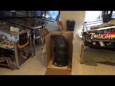
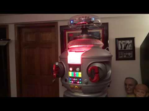
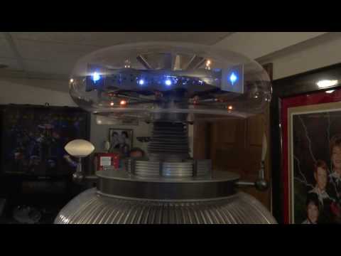
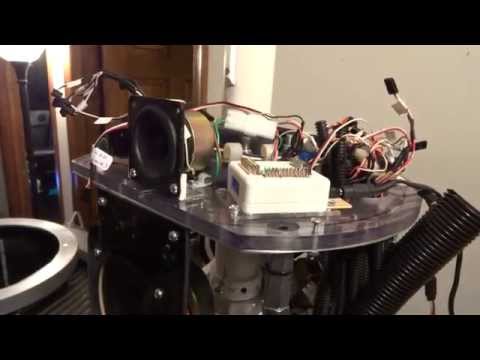
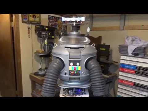
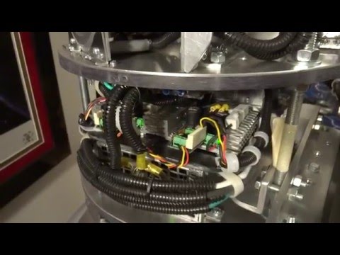
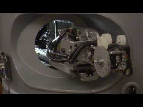
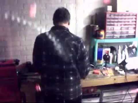
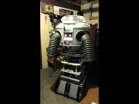
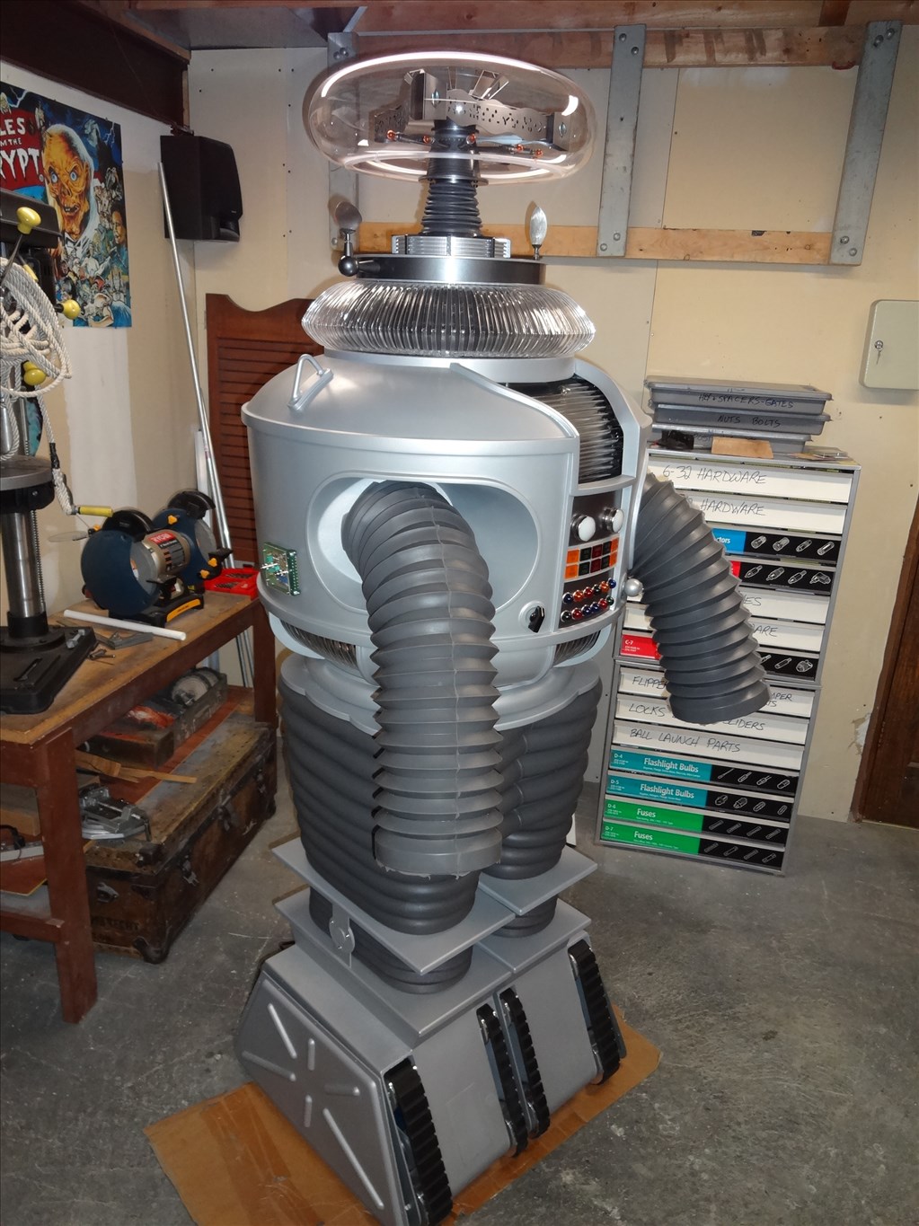
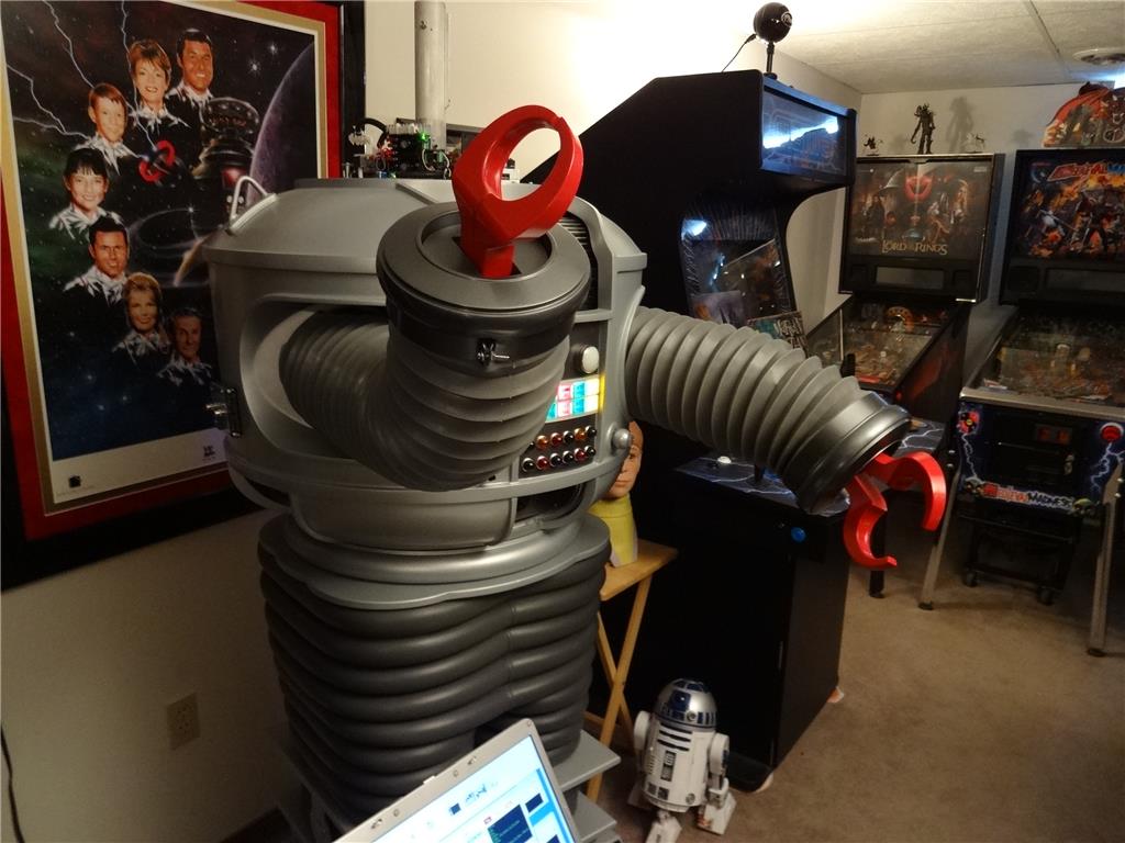
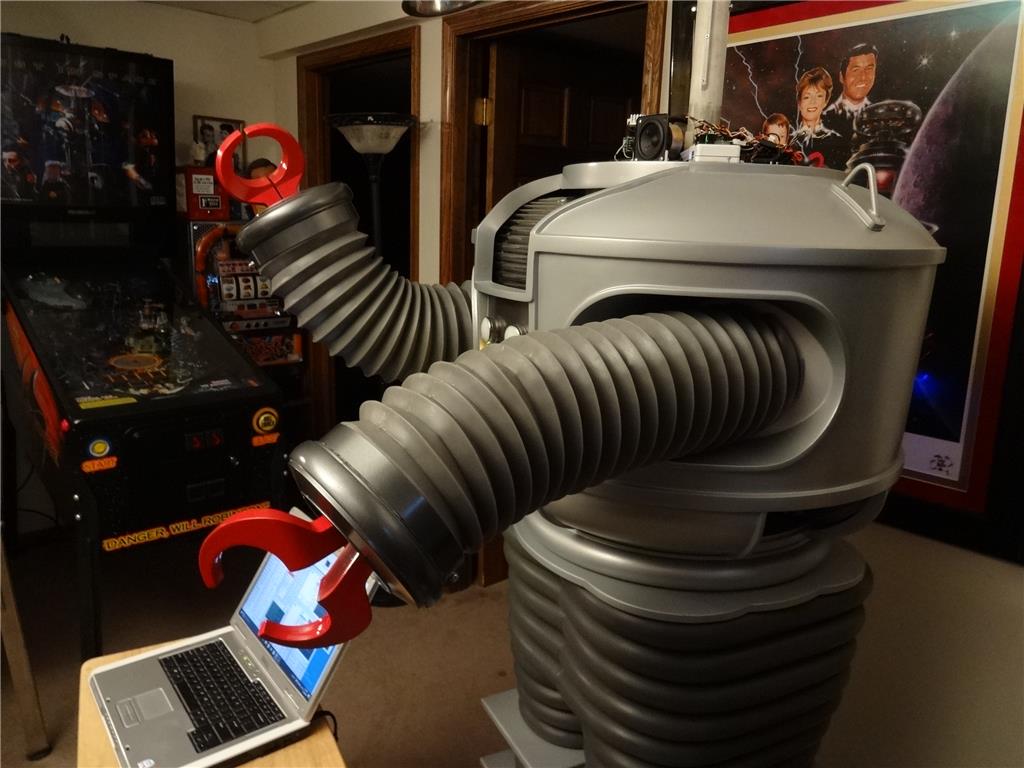
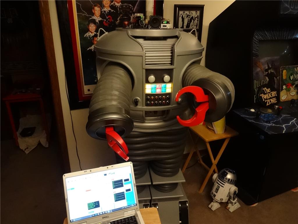
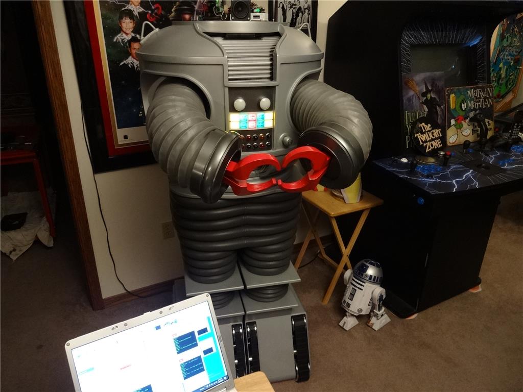
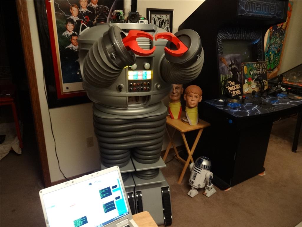
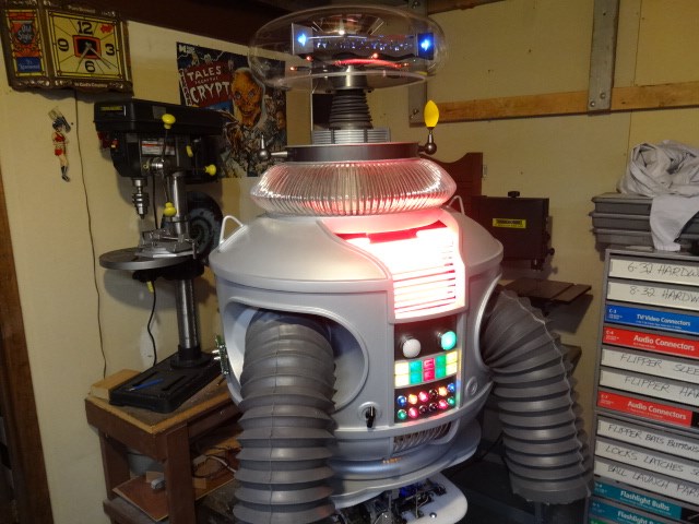
I'd like to share a video I just took of my full size Lost in Space B9 robot that's controlled by two EZ-B controller boards. Right now they are controlling limited movement and voice response of a few motors, lights and sound files played from a Sparkfun MP3 Trigger board. Although I'm just starting with the animation and have more building on the actual robot the result (mostly thanks to the EZ Robot controller board) is shocking. Please have a look at this (4 minute) You Tube vid and enjoy.
Please excuse some Technical camera lighting and sound issues. This is the first time I'd made and posted a vid online.
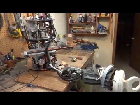
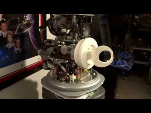
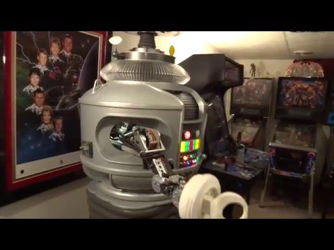
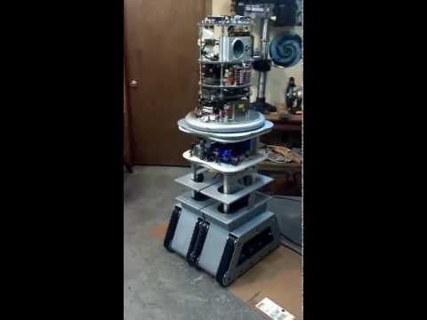
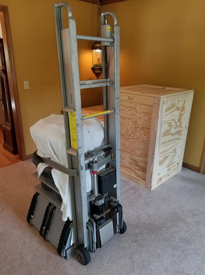
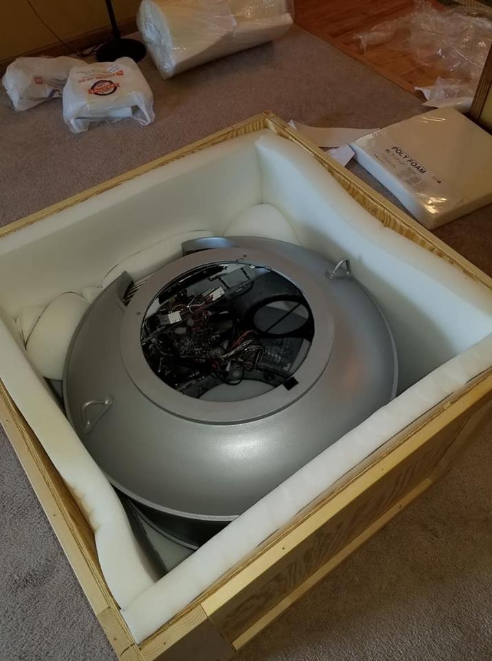
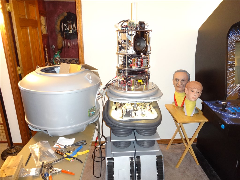
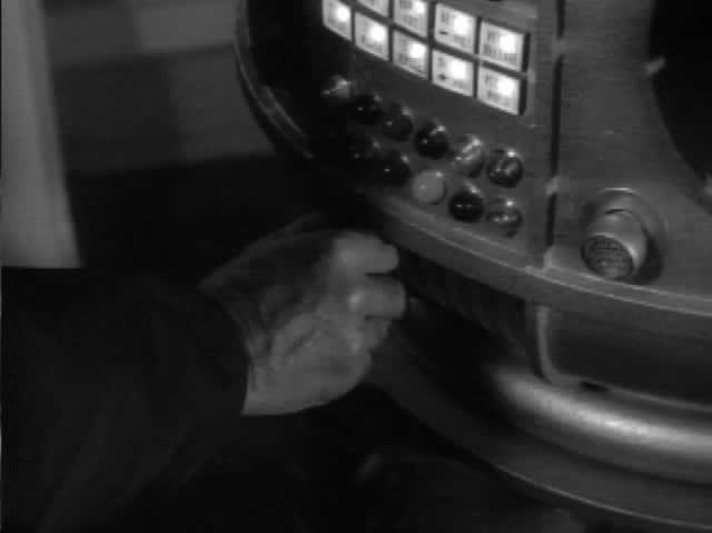
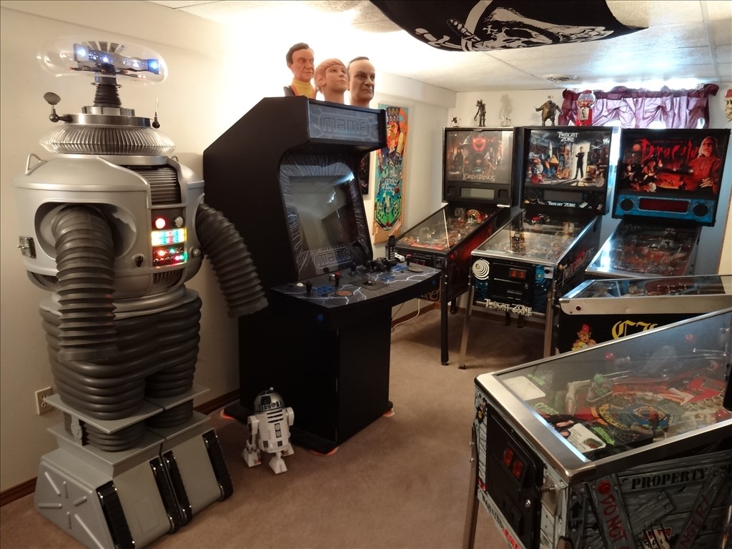
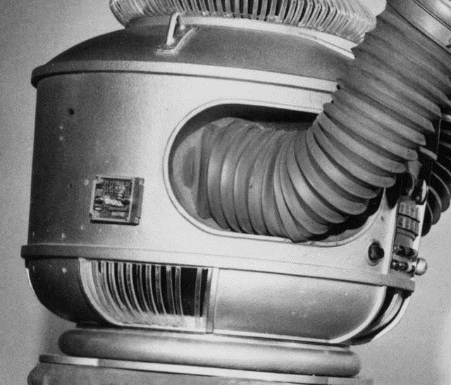
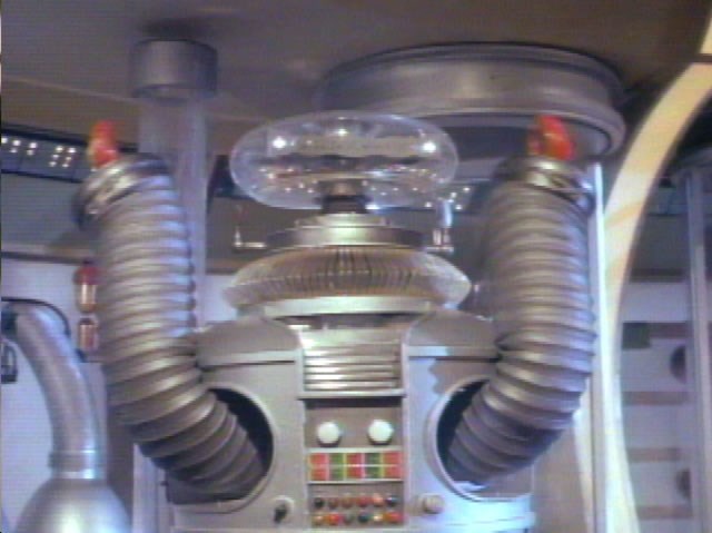
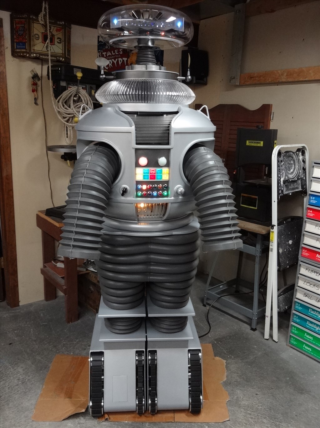
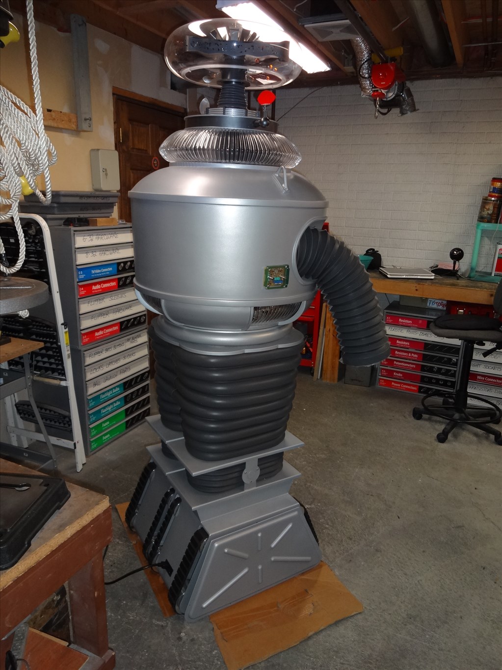
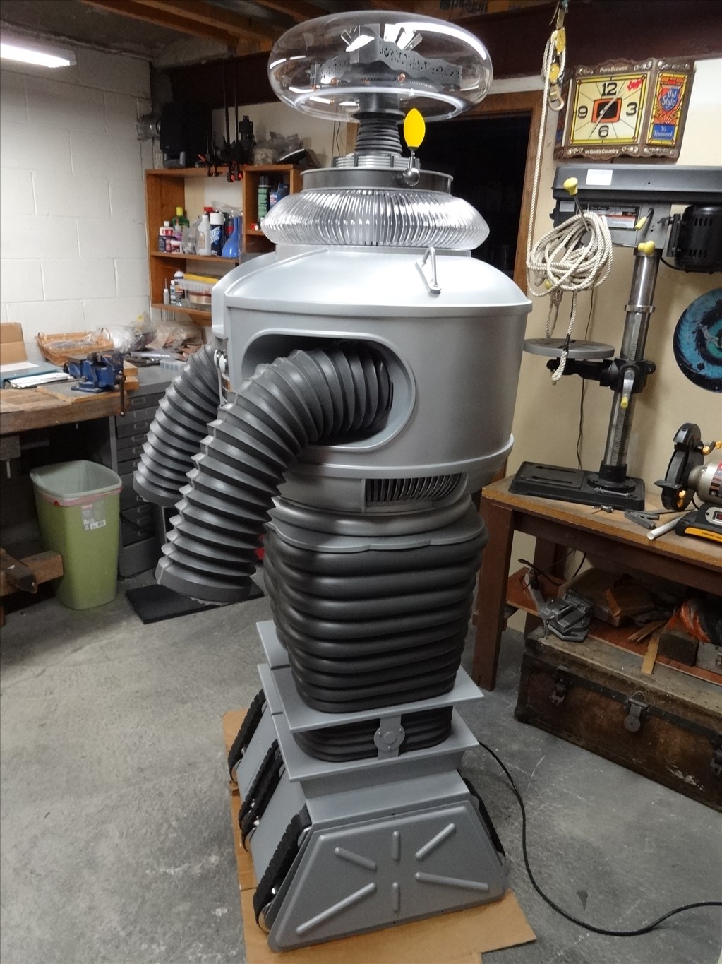
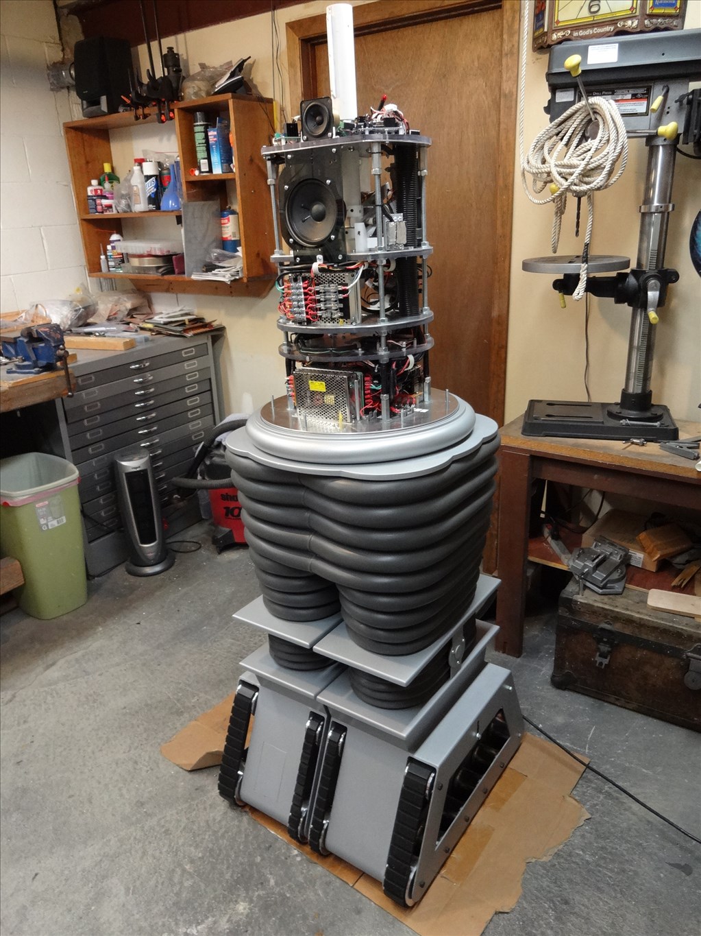
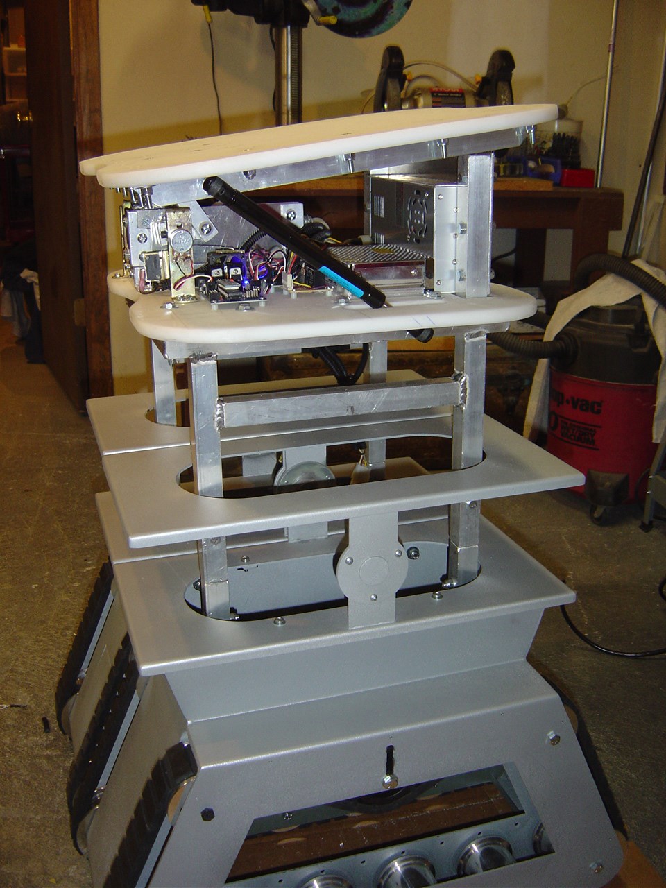
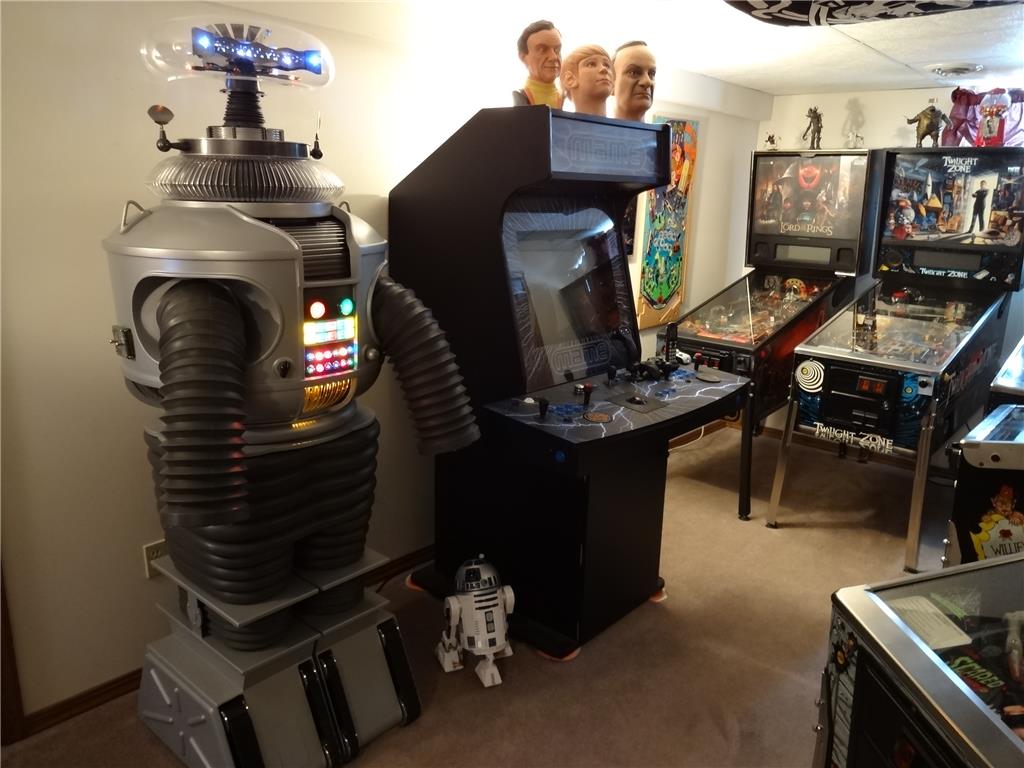
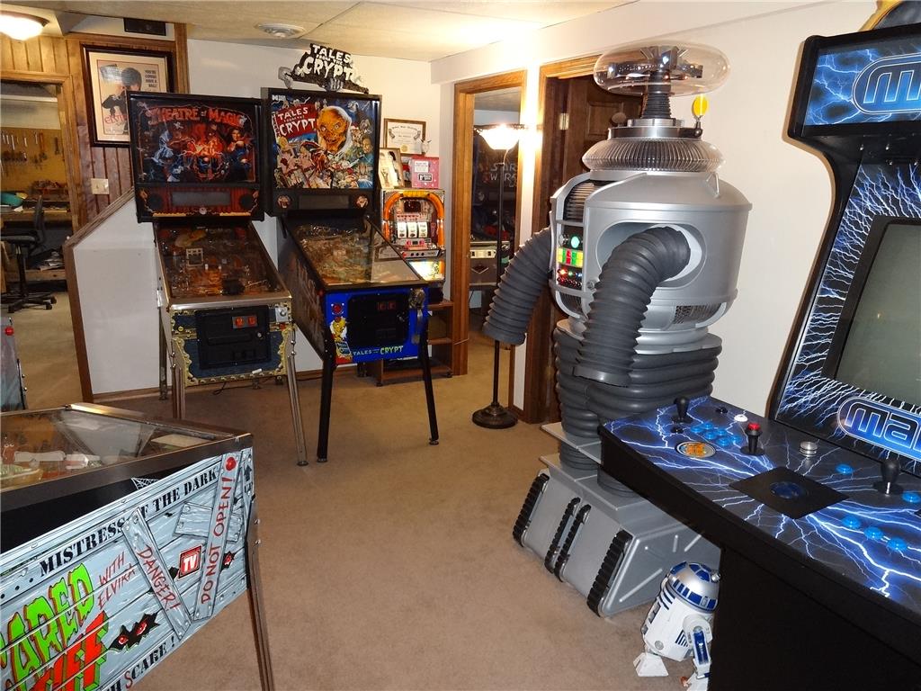
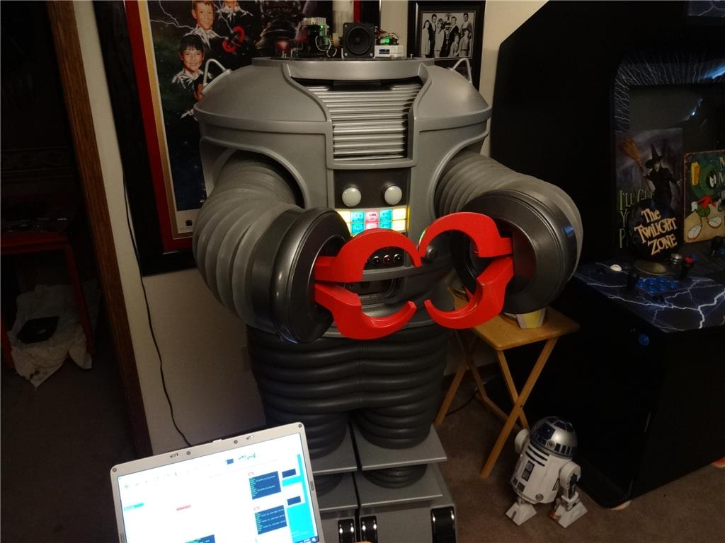
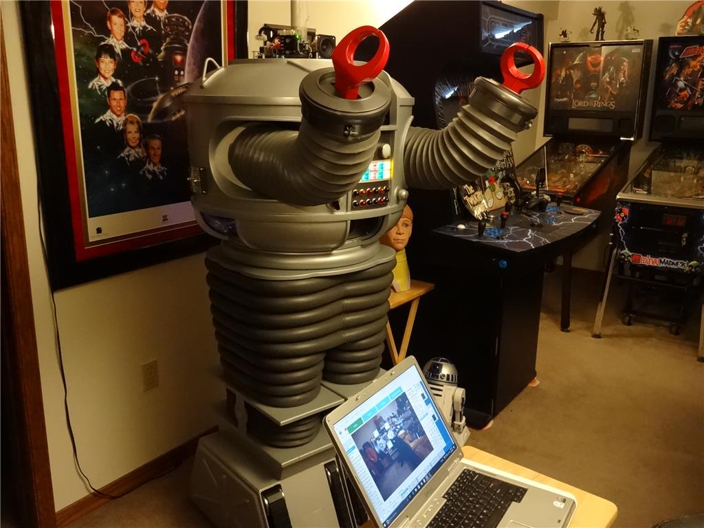
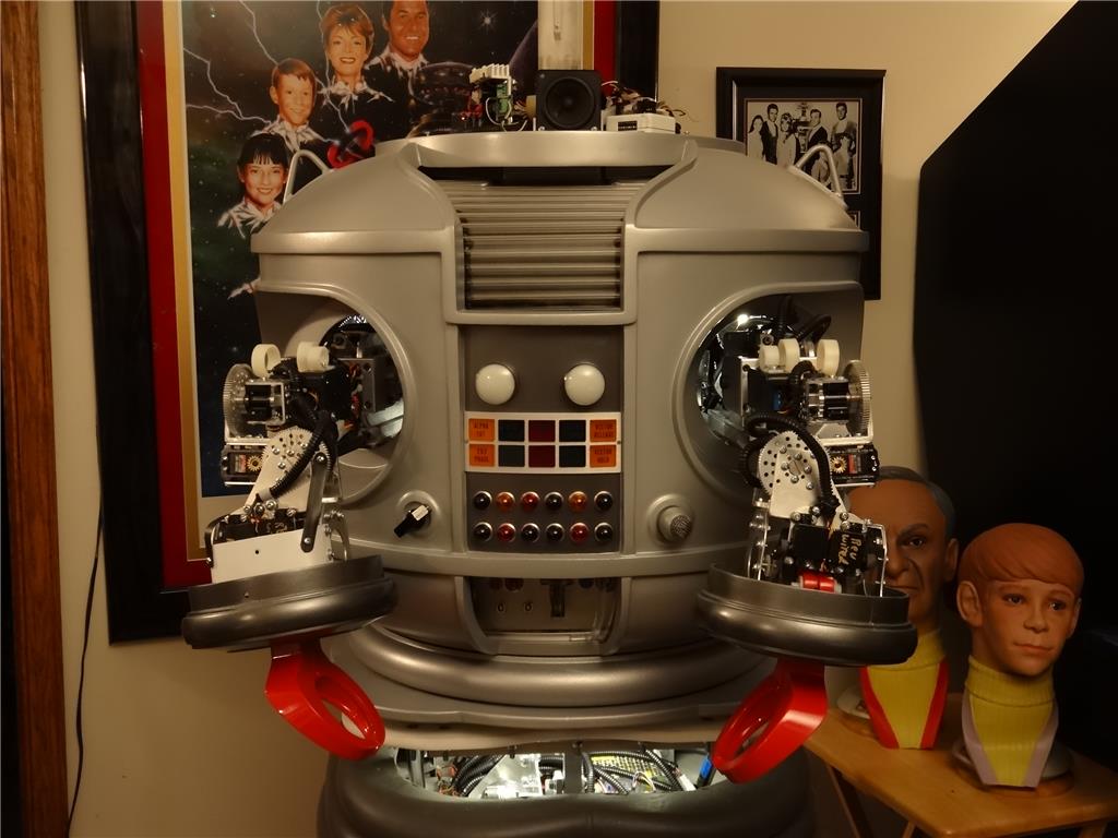
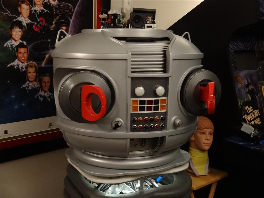
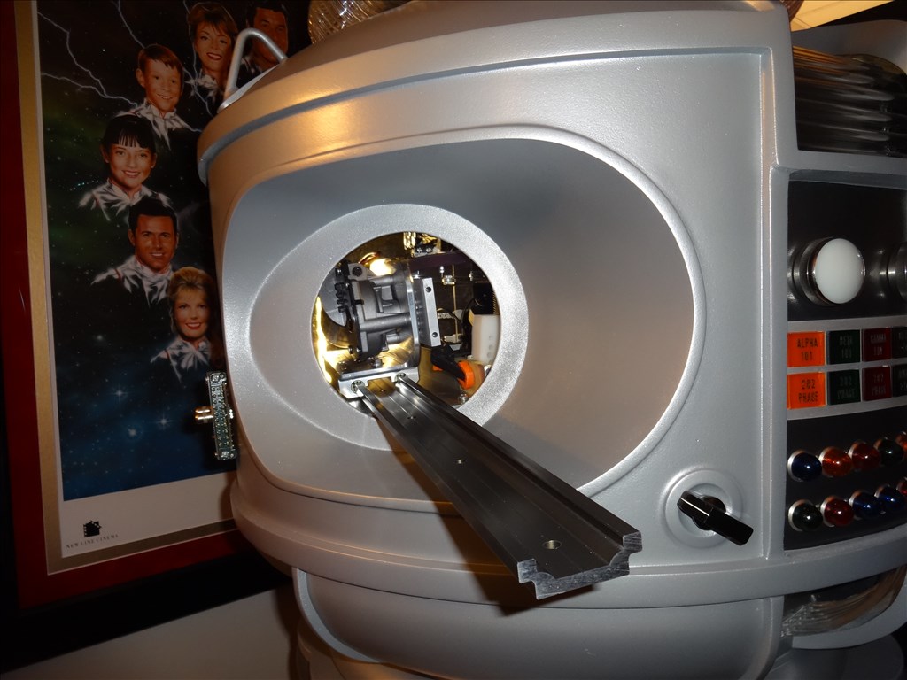
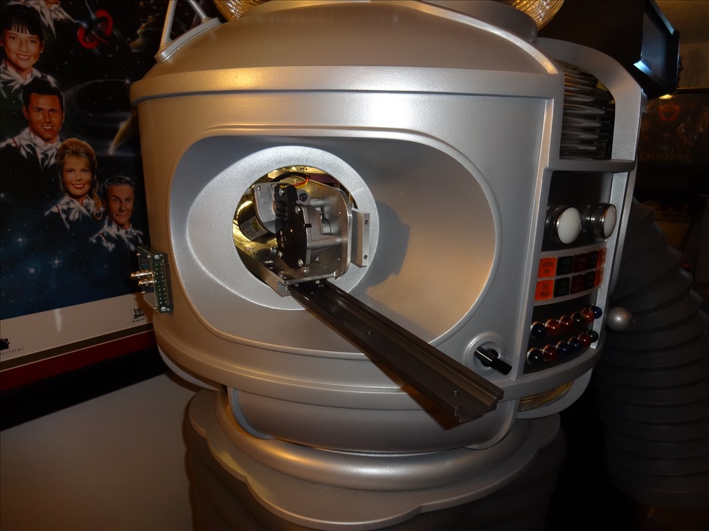
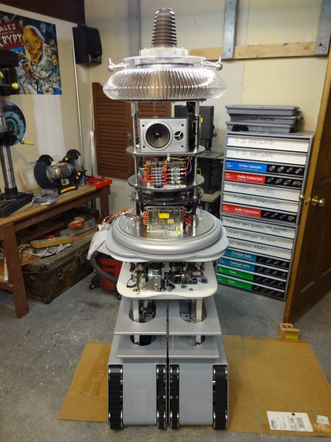
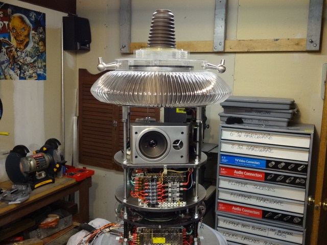
EDIT 8/2/13: Just realized I have no good pictures of how my B9 will look when complete. Here's one of the actual TV robots from the 60's TZ show Lost in Space and one recent shot of where I'm at with my build over 1 1/2 year after I started. Enjoy:


Thanks, Dave Schulpius
Discover more robots
Faengelm's A Fun Use Of Virtual Servos
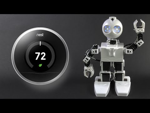
DJ's Jd Connects To Nest Thermostat

Thanks again everyone. Your support really helps me to keep going and motivated.
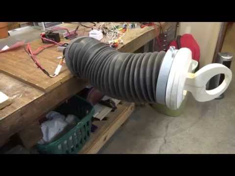
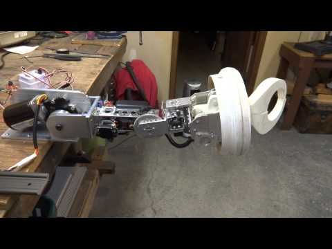
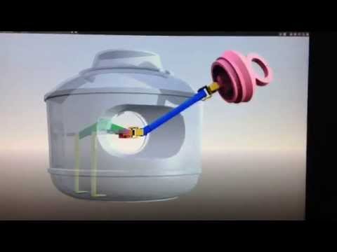
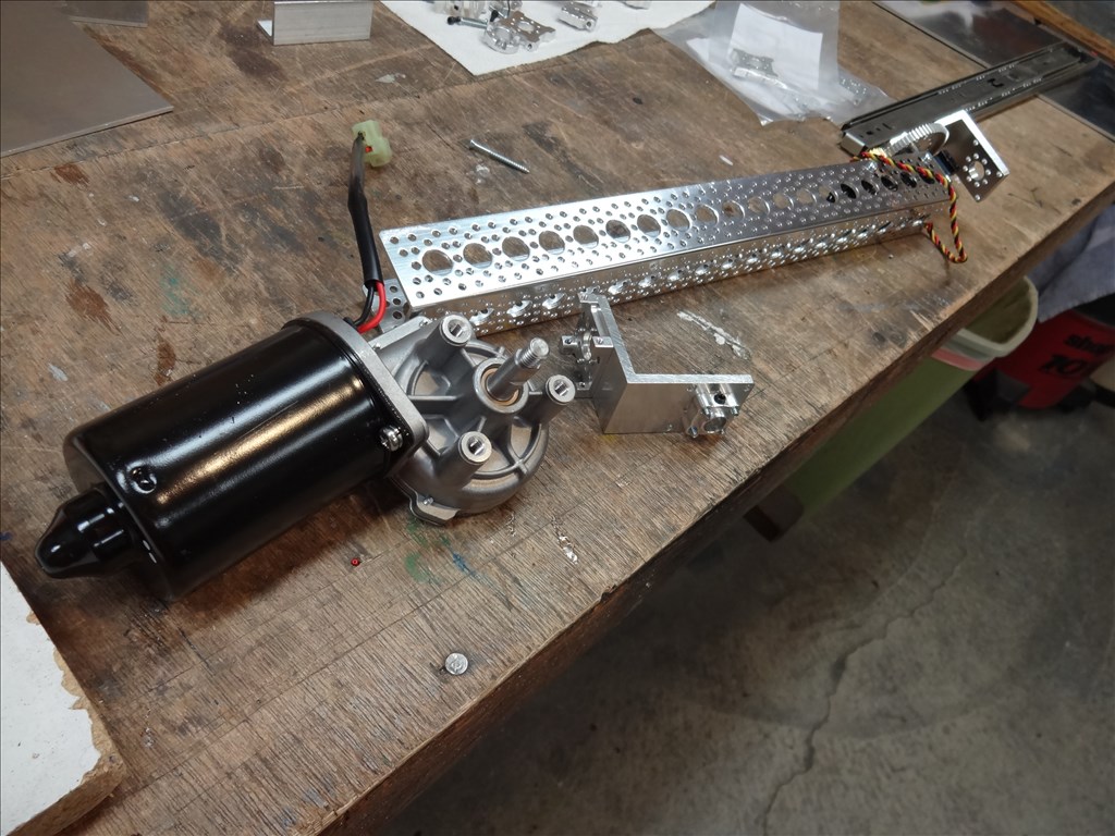
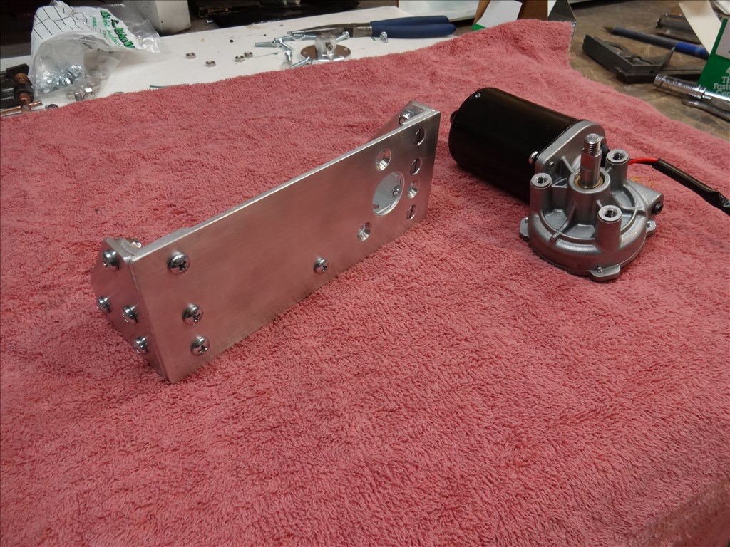
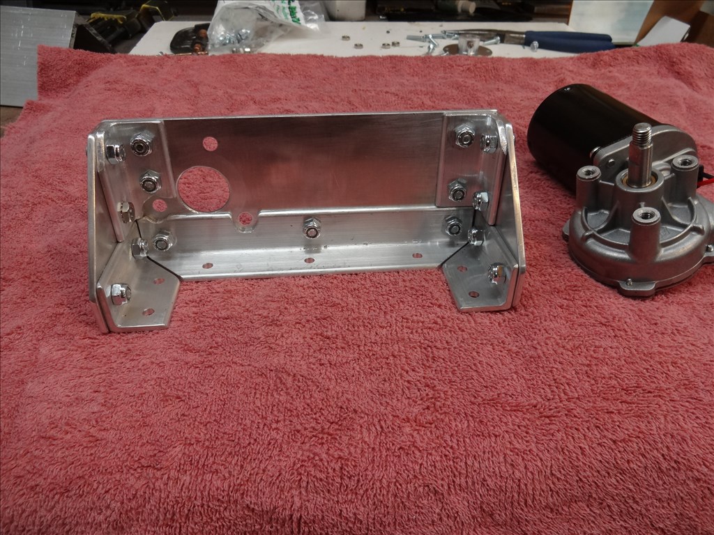
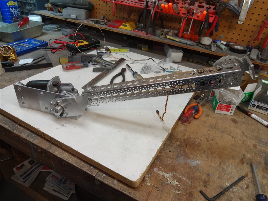
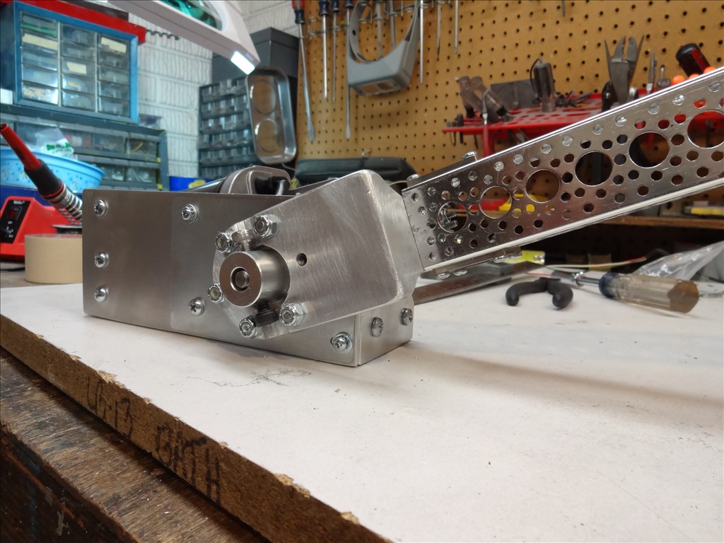
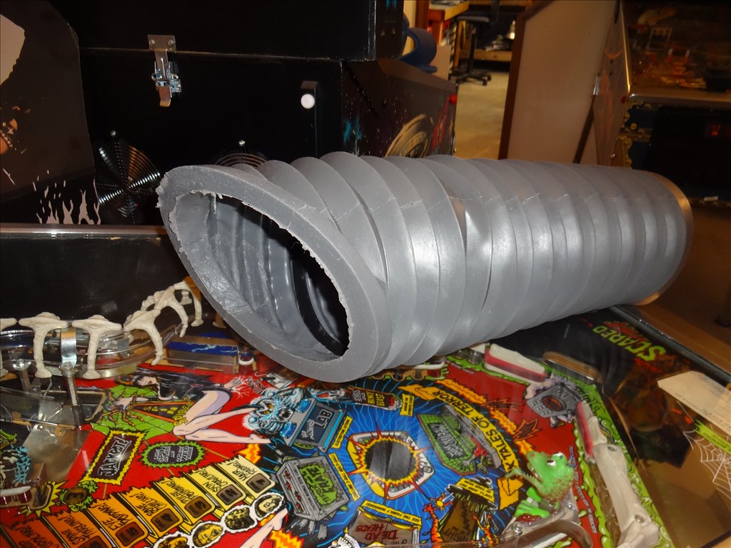
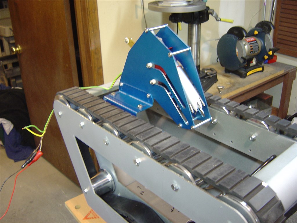
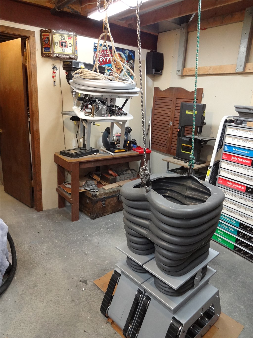
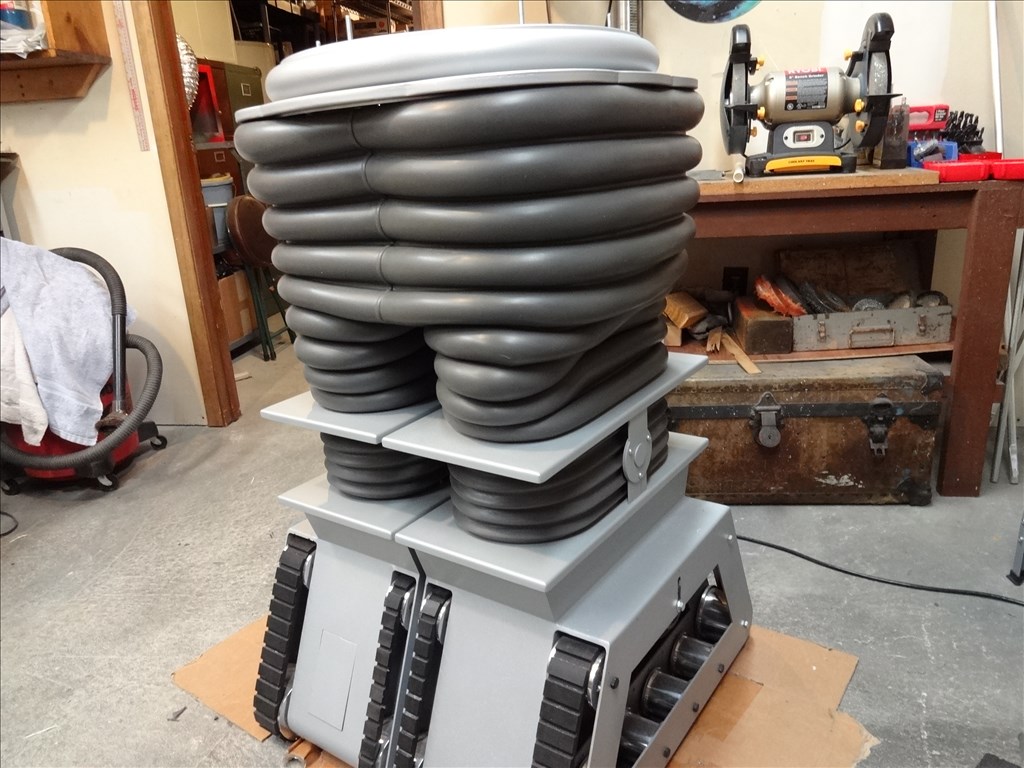
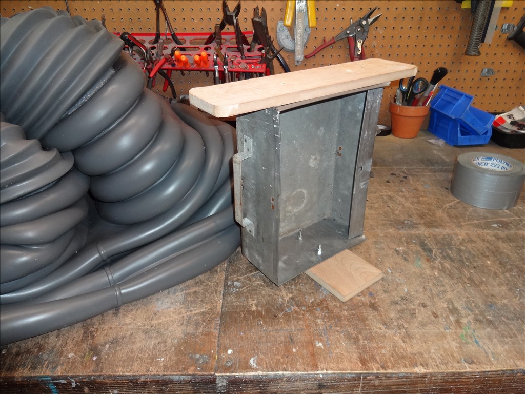
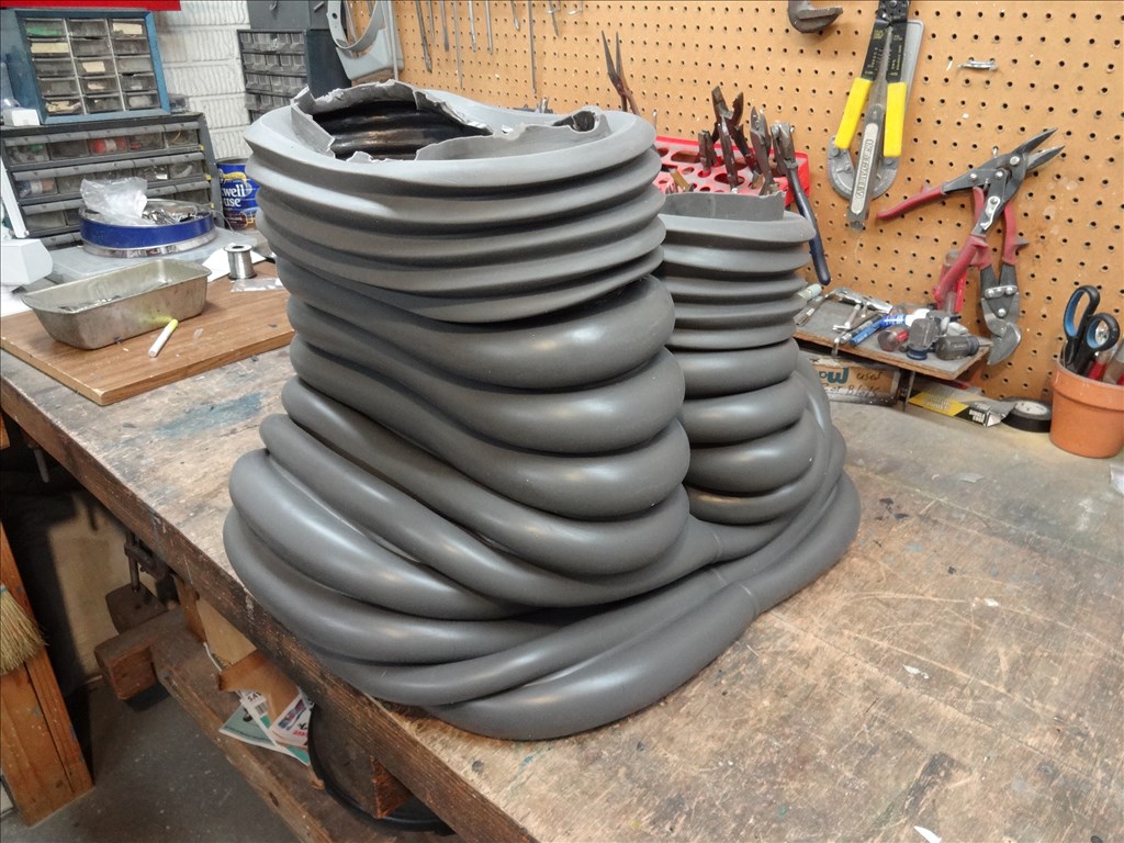
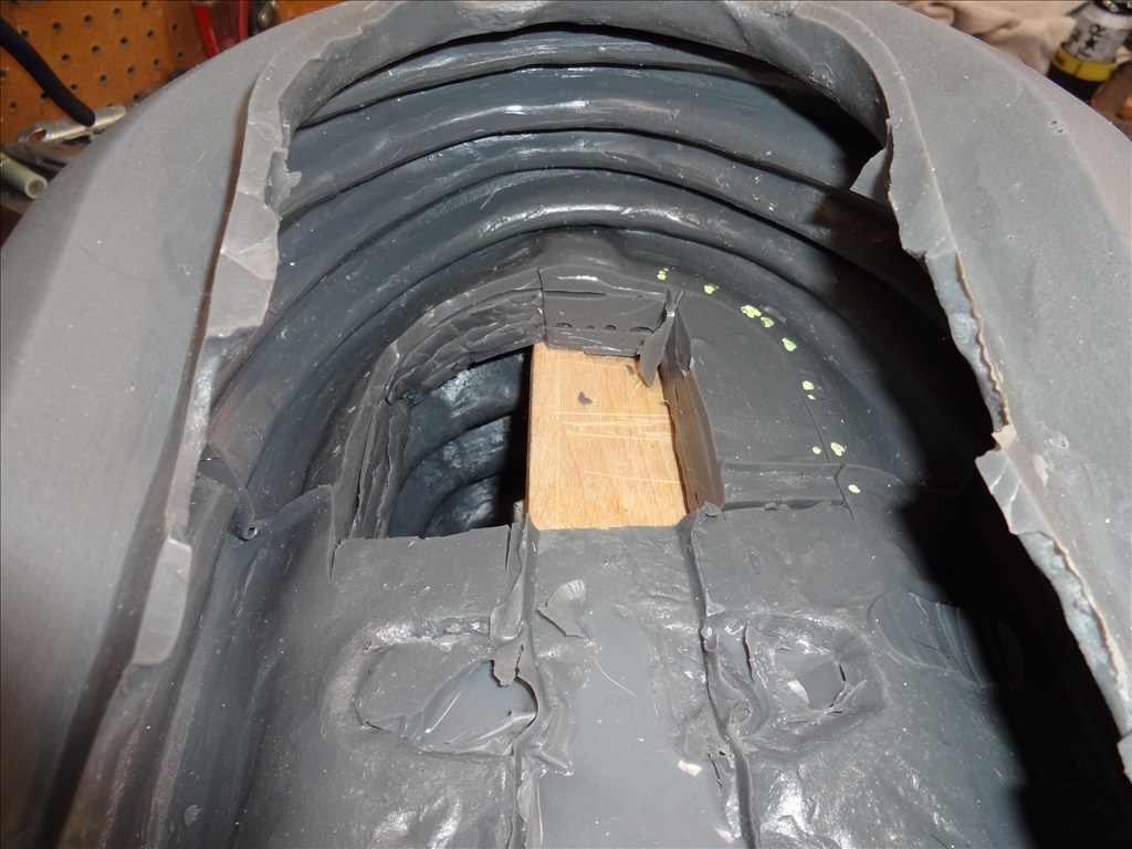
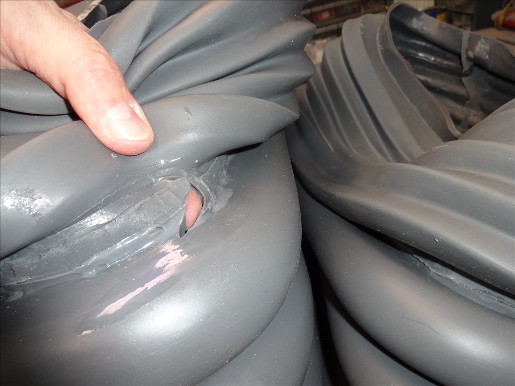
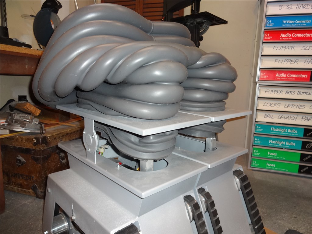
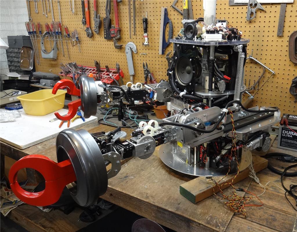
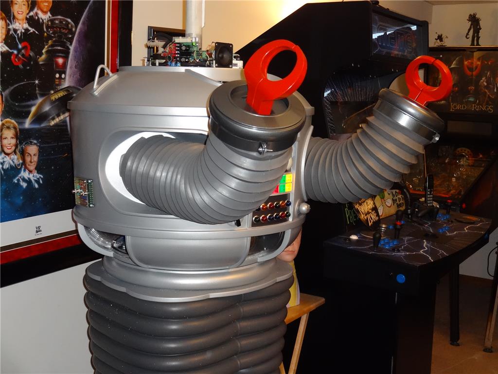
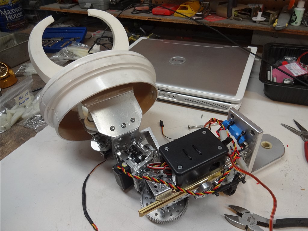
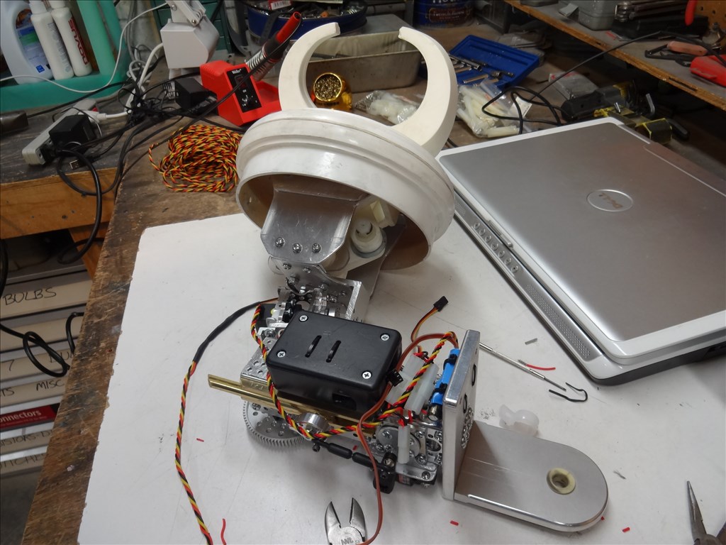
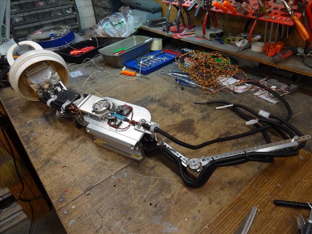
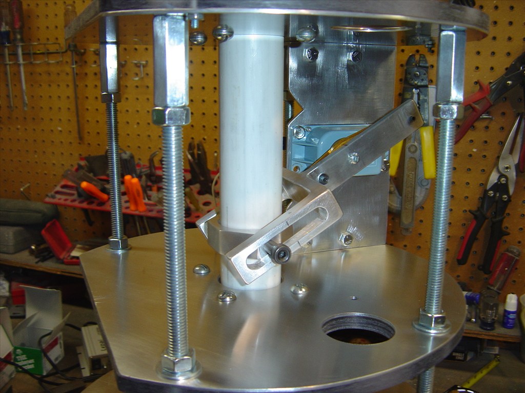
When dreamed this thing up I had no idea it would look so real when it moved around. I think a large part of the realism is Will Huff's high quality arm skin and the ease of programing that EZ Robot offers. Without them this arm would be a "misguided mechanical misery" to borrow one of Dr Smith's names for our "old booby".
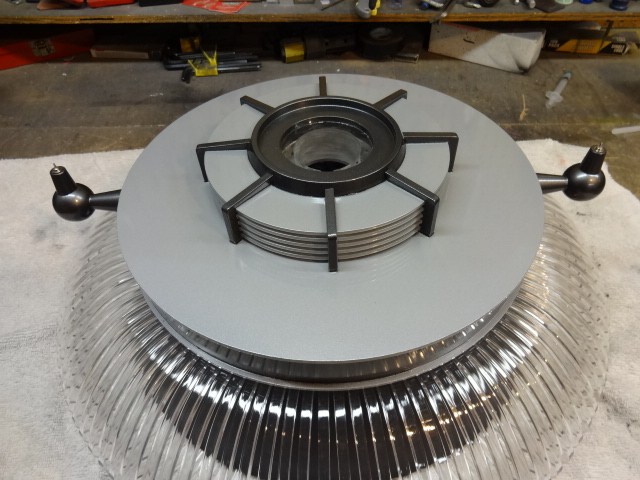
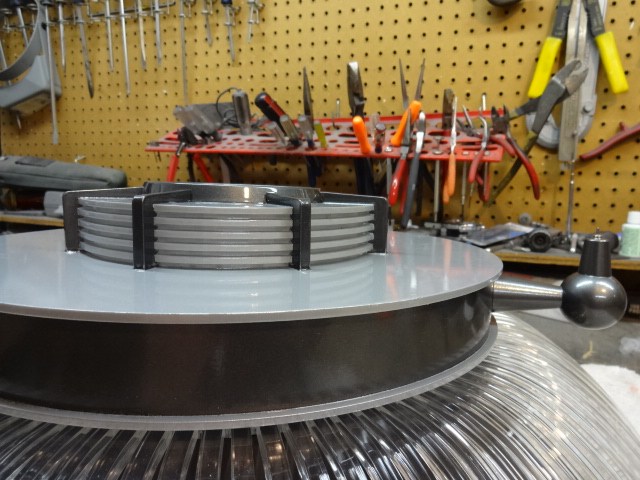
Hi gang,
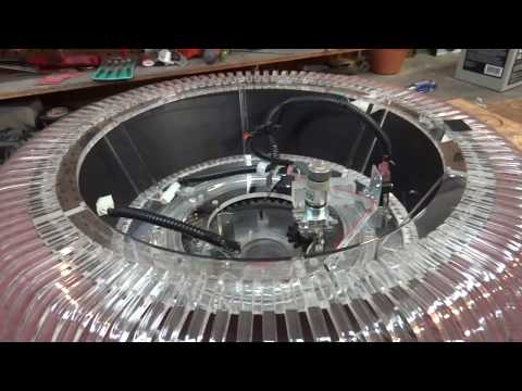
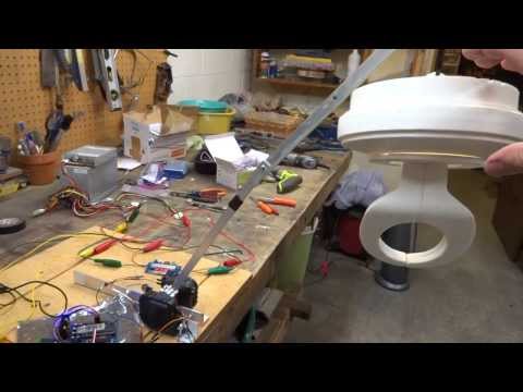
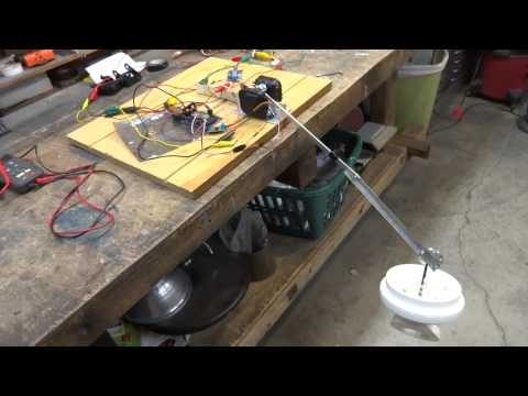
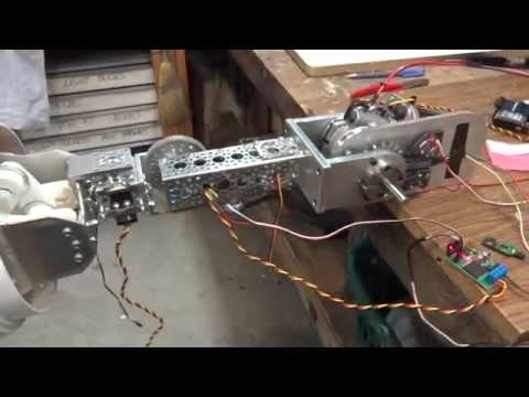
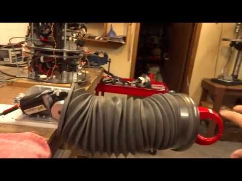
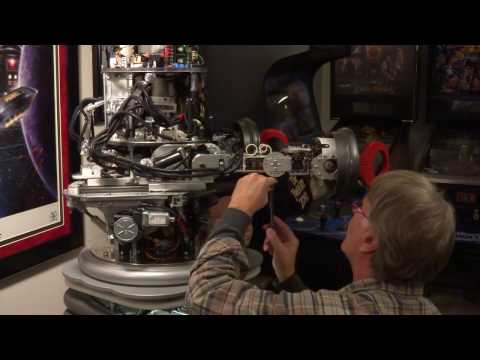
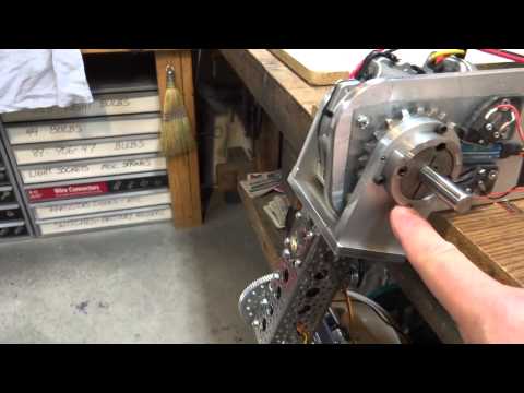
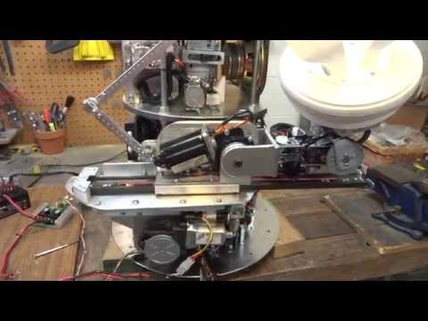
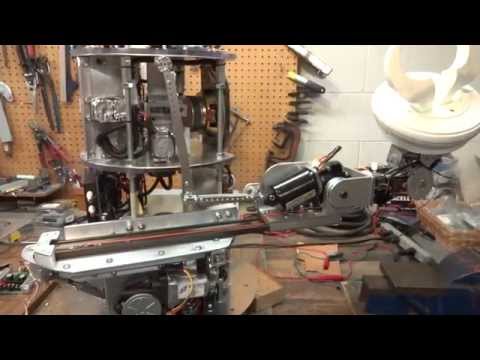
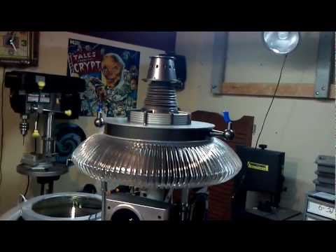
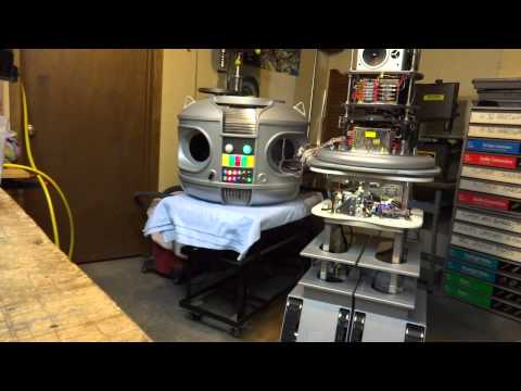
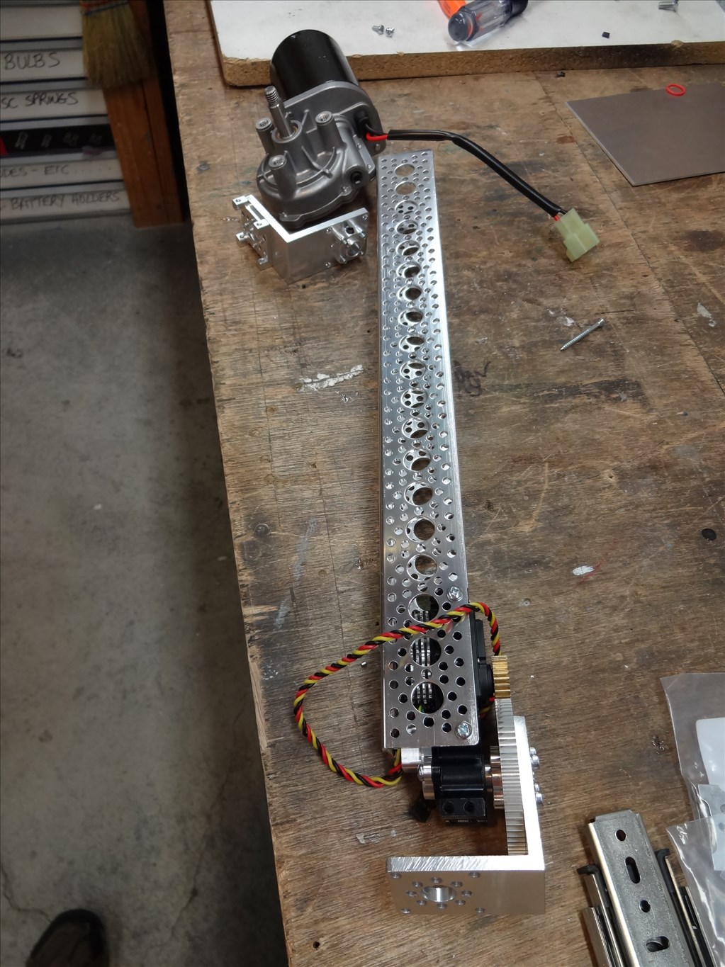
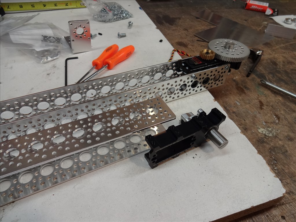
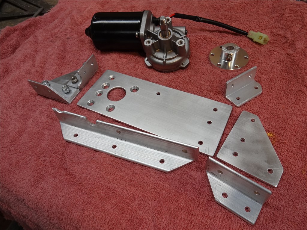
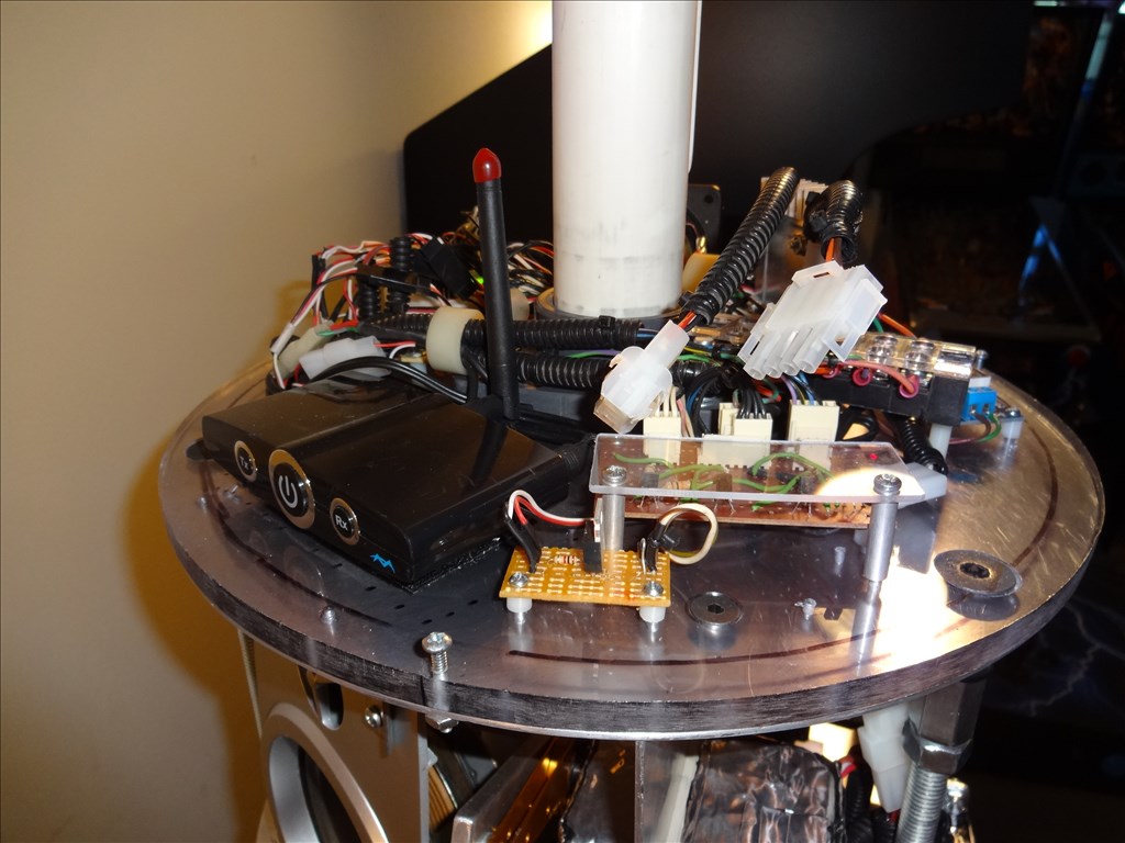
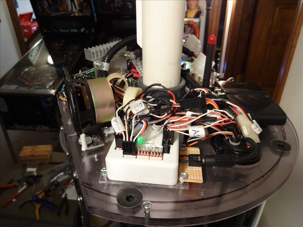
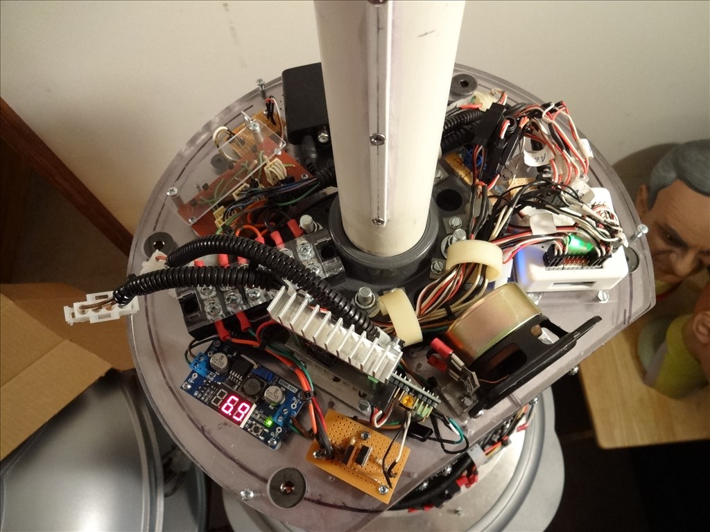
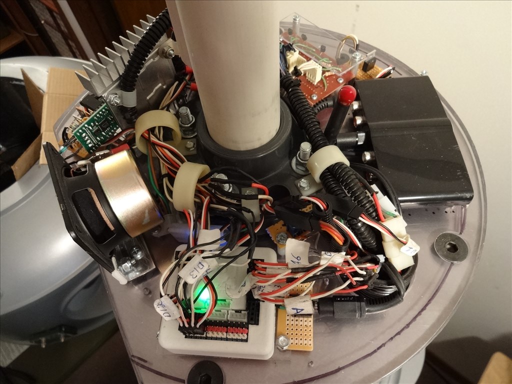
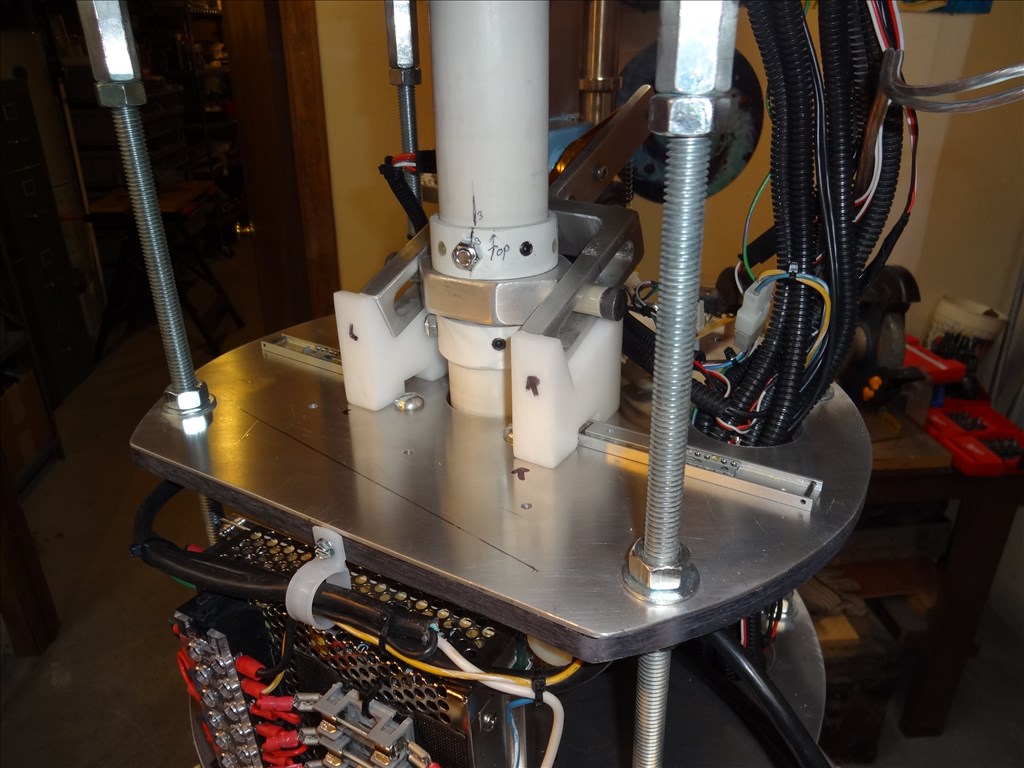
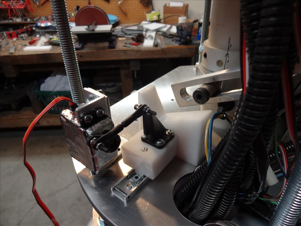
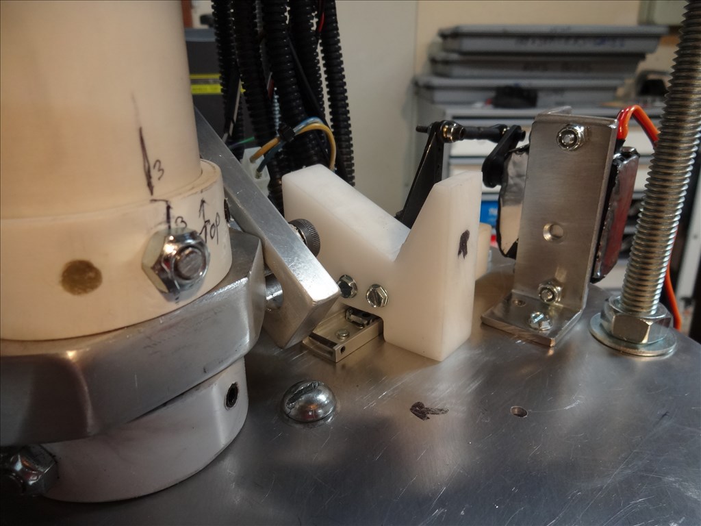
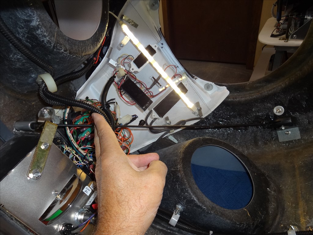
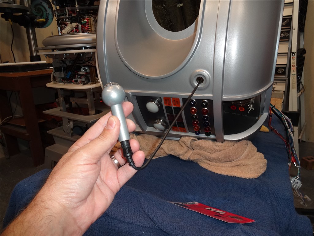
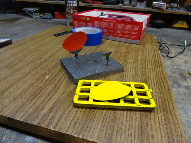
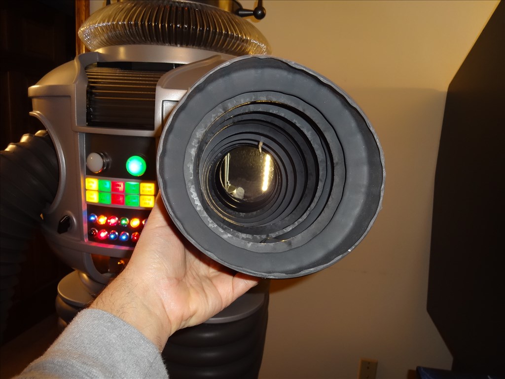
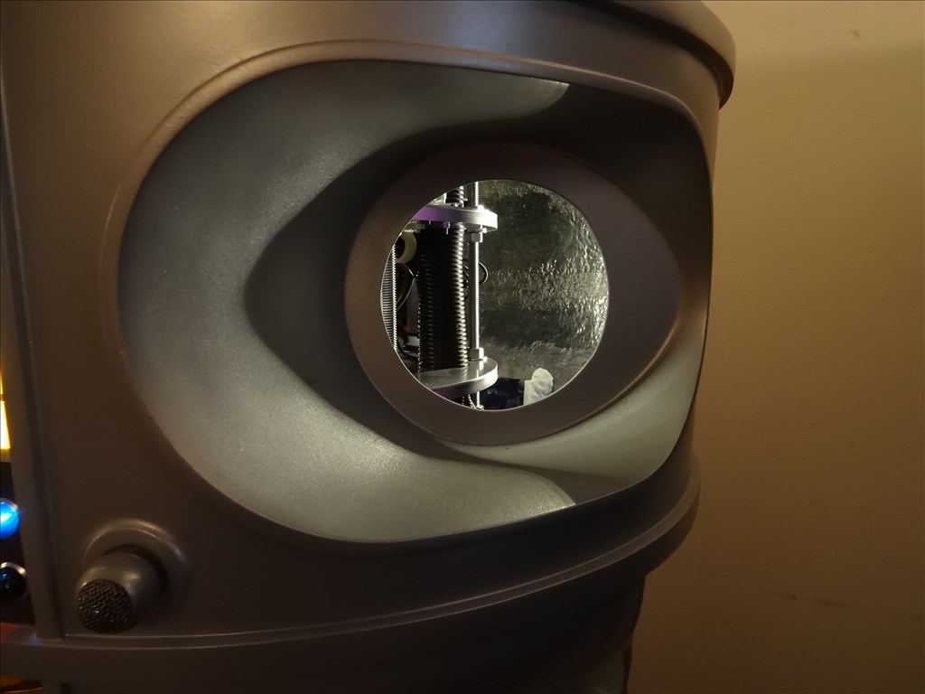
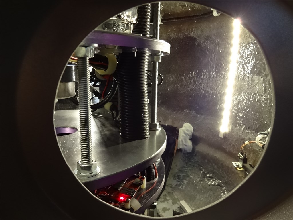
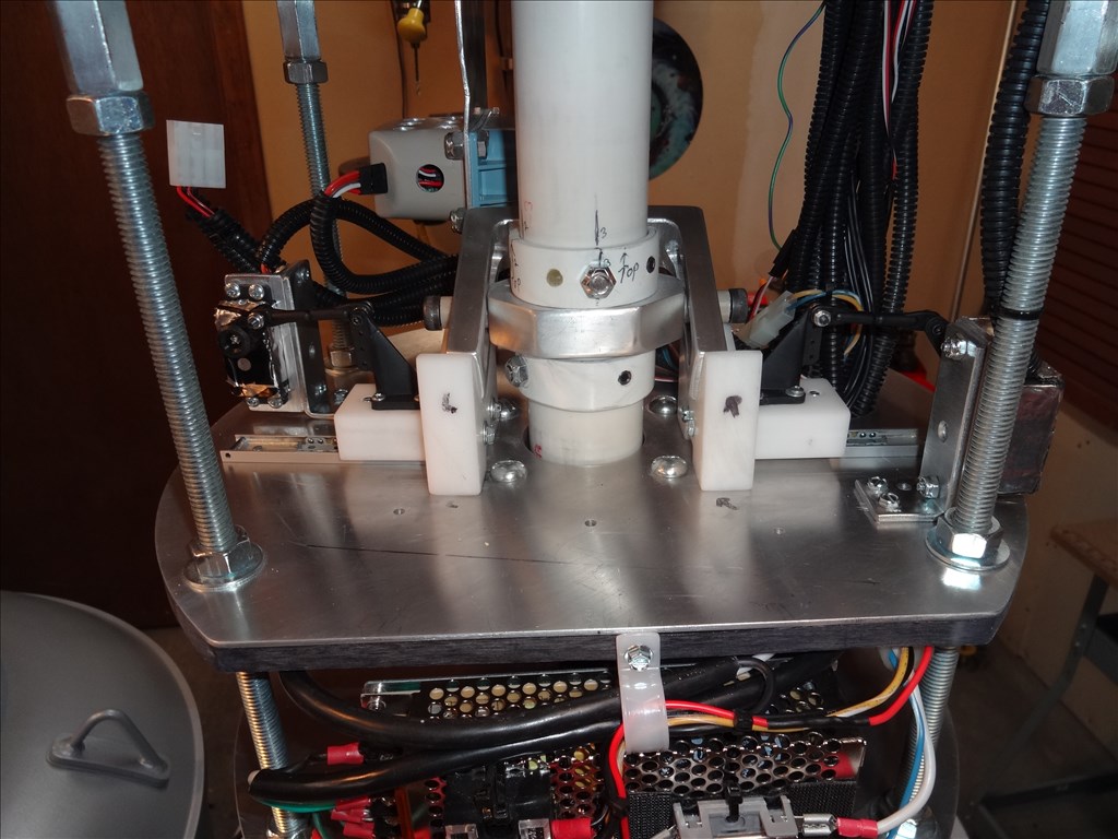
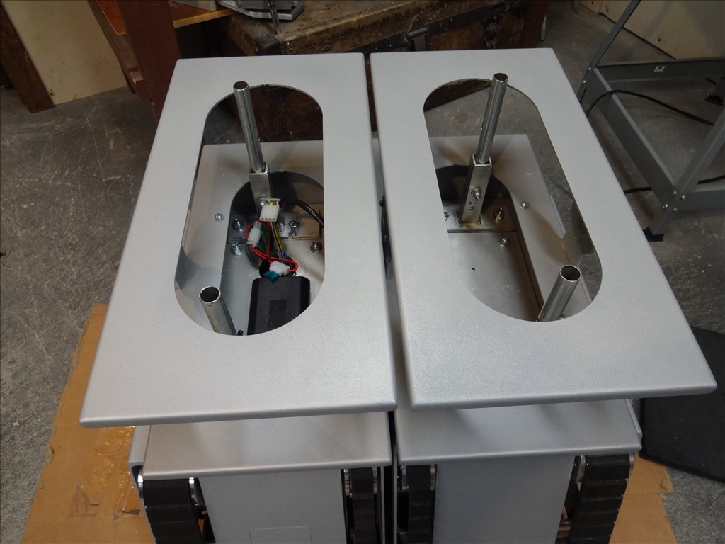
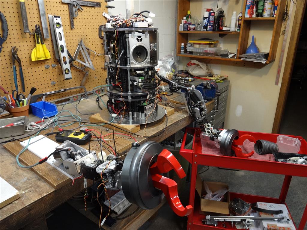
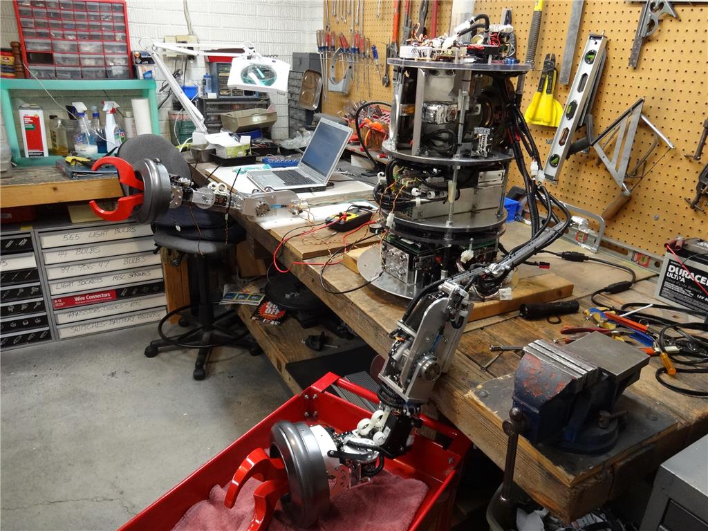
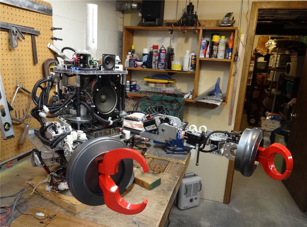
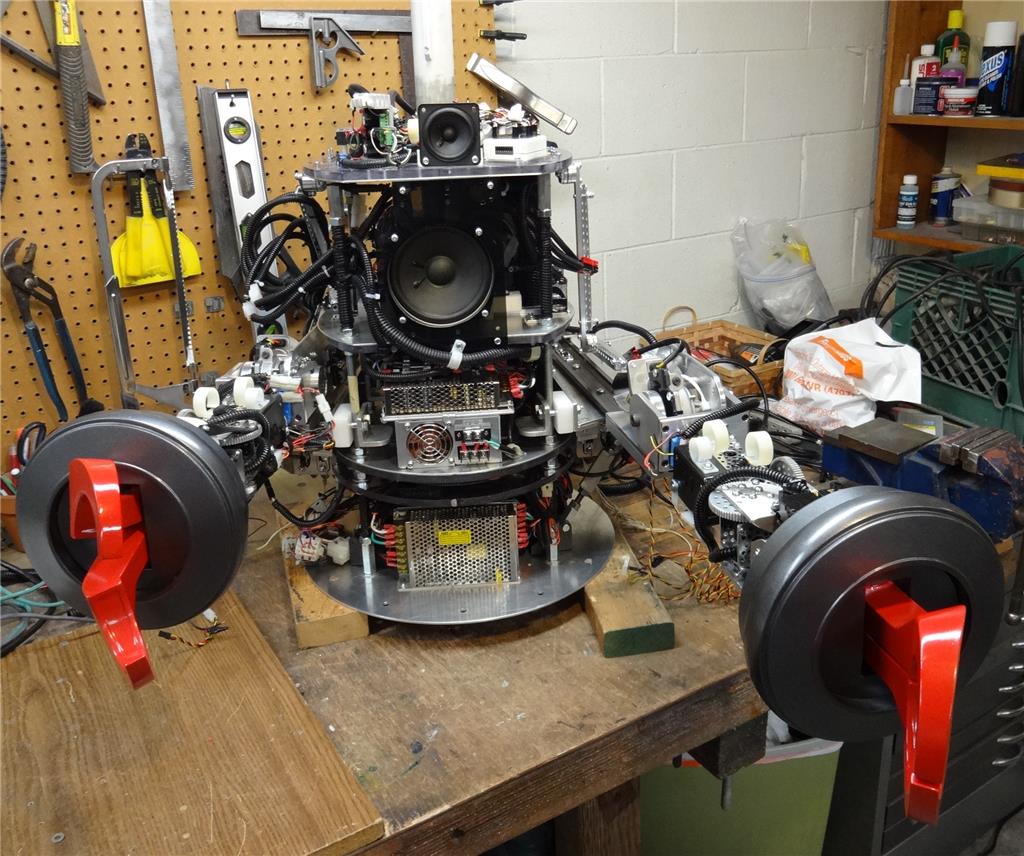
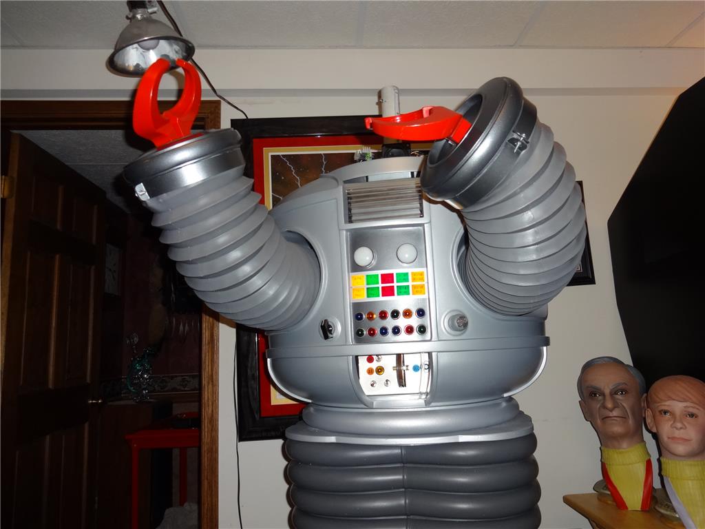
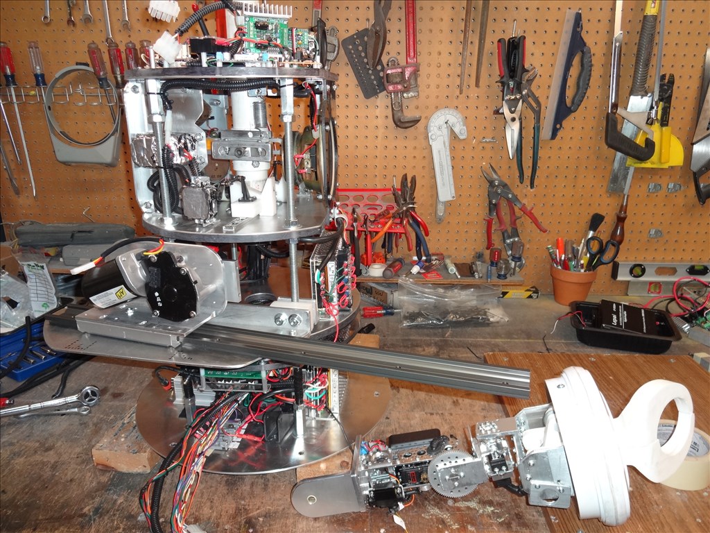
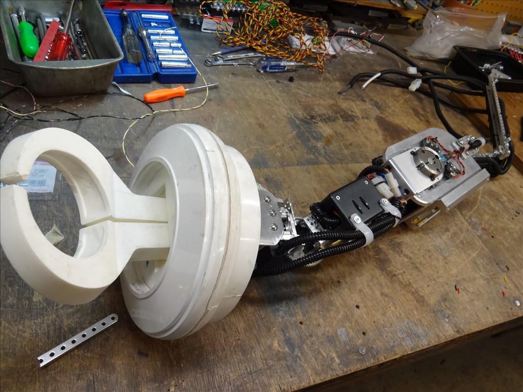
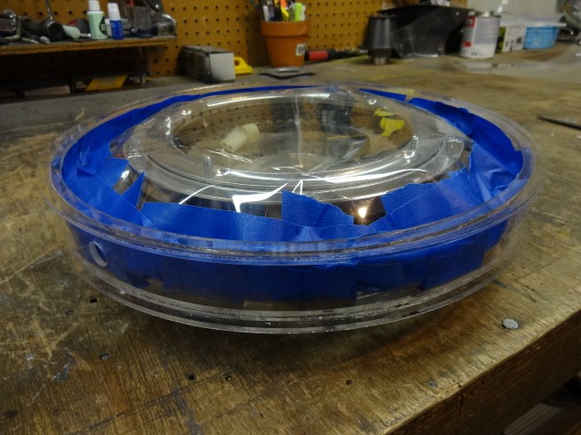
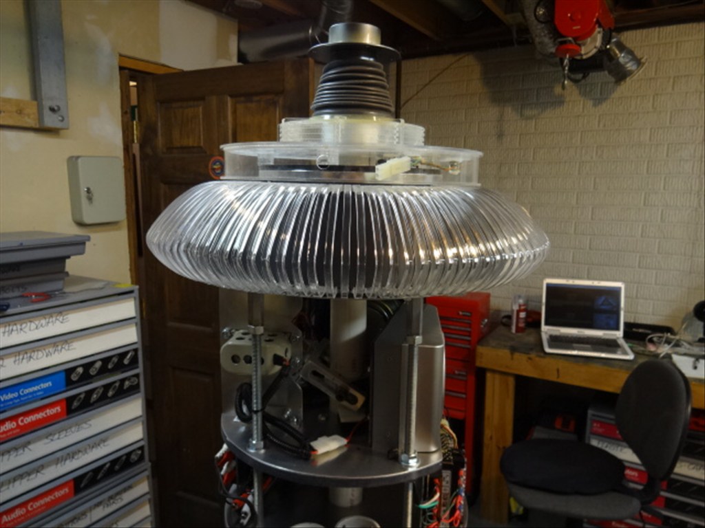
I'm getting very close to finishing up my B9 Arm. Actually it's mostly done unless I come across a component needing a redesign. I'm in the coding and control phase right now.
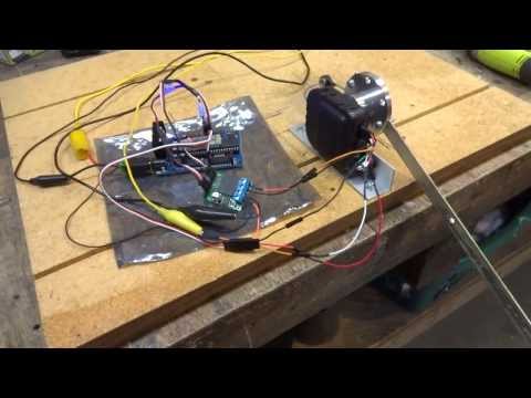
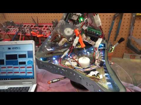
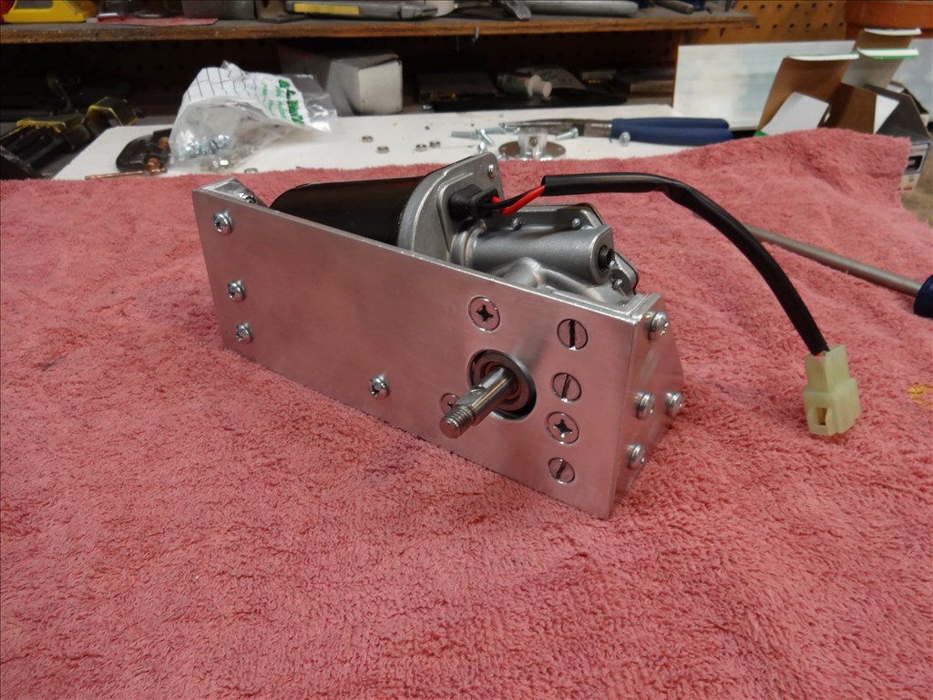
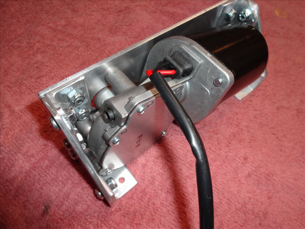
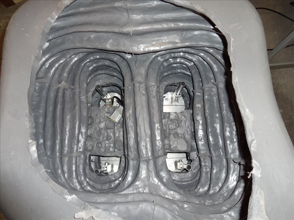
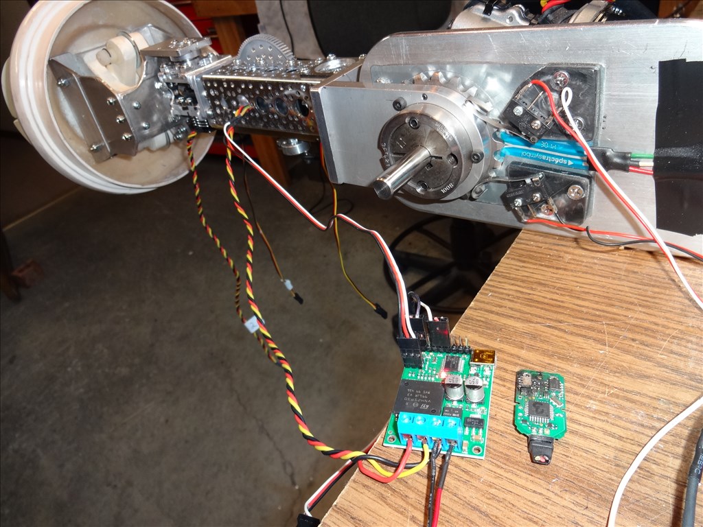
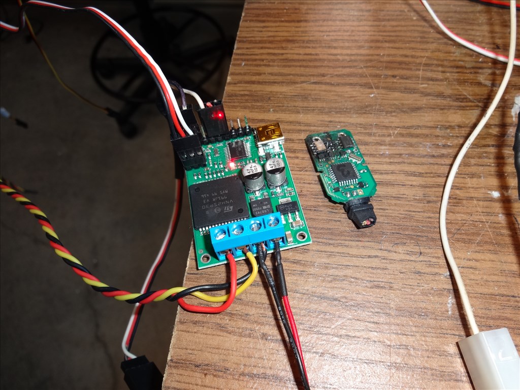
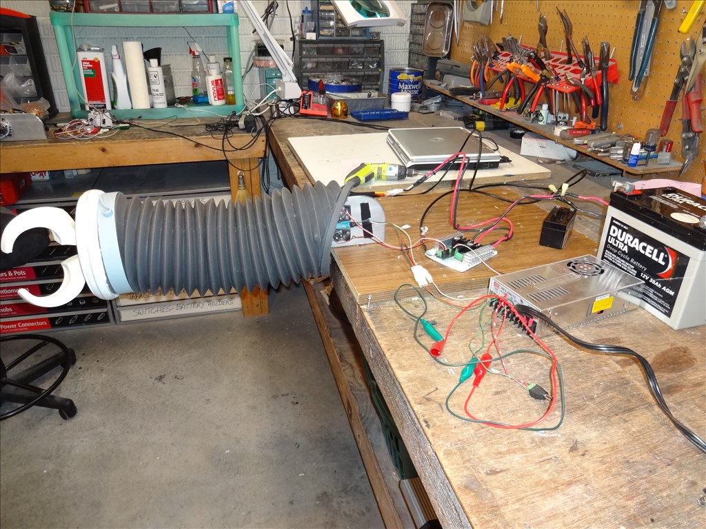
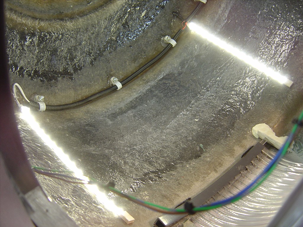
I thought I'd share this video I took last night. It's actually meant to send to Demention Engineering (Kangaroo X2) and Sptra Symble (Softpot) for troubleshooting help. It's long at 1/2 hour and kinda technical but you may enjoy it. I'm having a small problem with my arm not stopping at the same point depending on what direction it's heading. I send the same stop point from each side and it reports back a different value and over shoots. Anyway, feel free to comment and have fun. Dave Schulpius :
Hey Dave,
What happens when you click the center script a second time after moving the arm up or down? It would be interesting to know if the arm moves up or down that little distance.
The reason that I am asking is that I have seen this with pots on Rafiki. The code on the arduino that I have moves the motor, then checks the pot, then moves the motor again to account for the variance. I do this because the arms pocket into the robot, so having an accurate position is important for me also. I actually do this 4 times, two times more quickly then two times really slowly to get the desired position. I would have thought that the kangaroo would handle this but it looks like its not slowing down soon enough to account for the final fine movements.
4 is probably overkill but I wanted to make sure it was at the correct position and I figured if I was going to write it to do this 2 times, 4 times had to be better, right?
An opto-switch is not an accurate device. It can't really be used for accurate positioning. The reason you can get different stopping points when going up and going down has to do with a particular opto-switch's characteristics. And that is going to vary from one unit to the next. They are really meant to be just on-off switches.
How it responds is governed by the specific characteristics of the led and photo-transistor used in the device you have. Those things can vary from unit to unit. Also there is the fact that the light pattern which comes from the led can vary. Some may have a nice uniform pattern of light falling on the photo-transistor while others can have a varying pattern depending on the point the light emitted is falling on the receiver. For instance, if the light falling on the top half of the photo-transistor is greater than on the bottom half, you will have to block more of the light going to the top half than the bottom half to get the same response. In your case this means the interrupter vane will have to travel farther in one direction than the other. The uneven reception characteristics of the photo-transistor is yet another factor. Again, it could be more sensitive on the top half than the bottom half resulting in the vane moving different distances to get the same response. ' How can you ameliorate these problems? One thing you can do is to make the hole on the both the photo-transistor and opto-switch sides smaller. This will reduce the variations mentioned above. Basically, the smaller the hole the more repeatably accurate it will be. Of course that also means less sensitivity overall. So it's a tradeoff. Another way would be to use a laser diode and photo-transistor. I'm not sure anyone makes one of those so you might have to roll your own. You would want a very narrow laser beam and that may require extra optics. Parts from an old cd player could work. But that's a long row to hoe to make it work.
Another method would be to calibrate the unit you have by creating a chart of position vs output. IOW, use something like a micrometer with a vane attached to the end and slowly move the vane into the opto-switch, measuring the voltage as you go. Move the vane in discreet steps of the same small amount each time. Then use these values to come up with correction factor algorithm in the software. How much you will move the vane each time will depend on the resolution you want the correction factor to have and the total distance it will have to travel to go from one end to the other. Unfortunately, if you ever change out the opto-switch, you will have to do that again for the new unit.
The best solution, however, is to use an optical chopper or an optical encoder. Either can give you repeatable accuracy in either direction. Of course either will be more difficult to install than the opto-coupler.
Nothing's ever easy is it?
EDIT One thing I forgot to mention would be to make the opto-switch adjustable in the vertical direction. By doing that you might be able to find a compromise position which will make the vane stop closer to the same point in both directions, even if not exact in either.
Thanks @WB for your always thoughtful and detailed information. Very useful and it helps a lot. I'll read through all this carefully and apply it to my build.
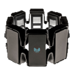
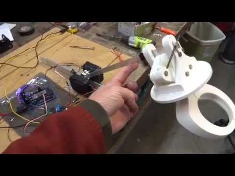
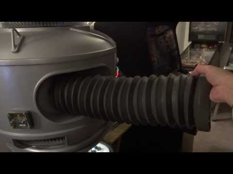
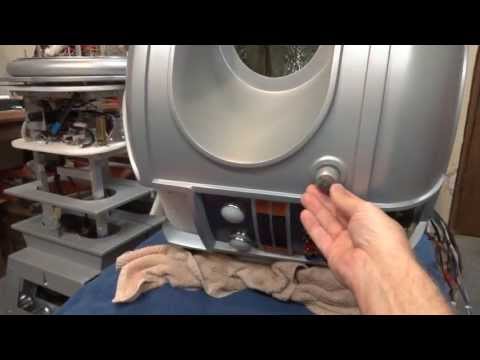
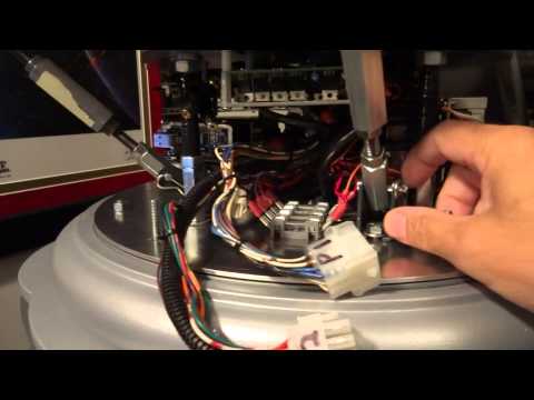
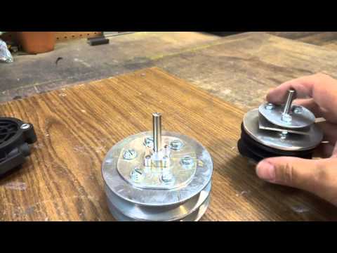
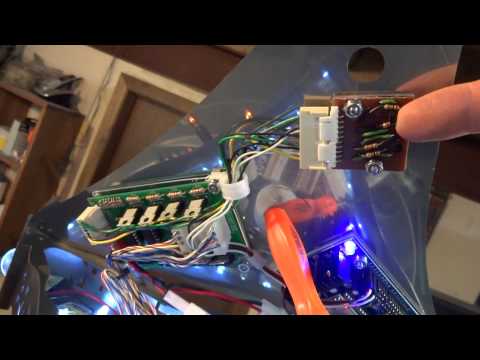
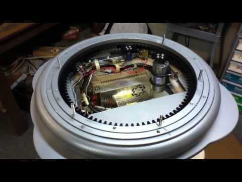
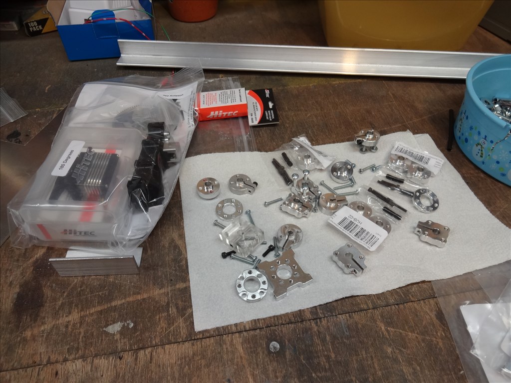
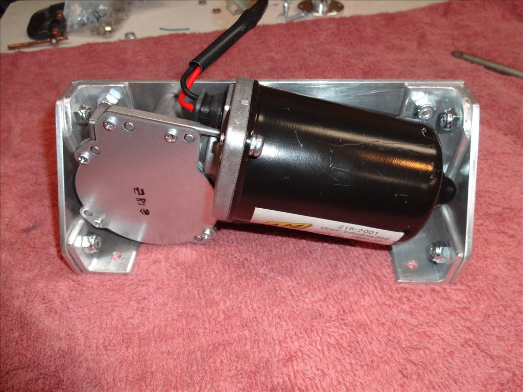
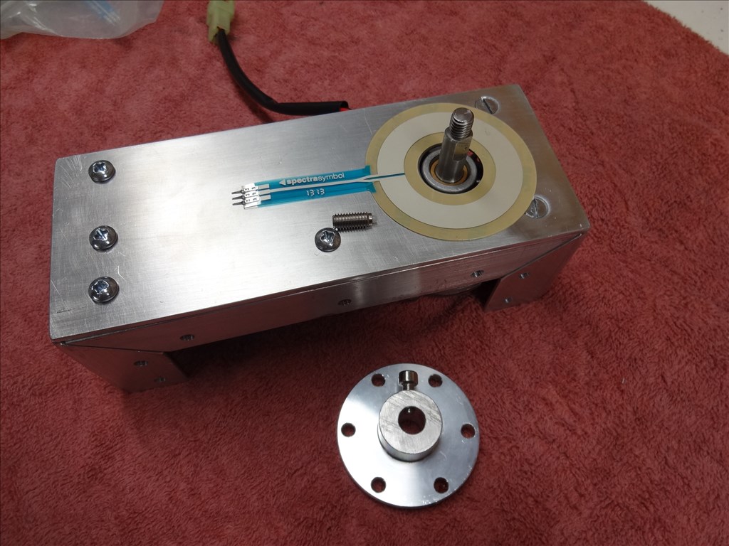
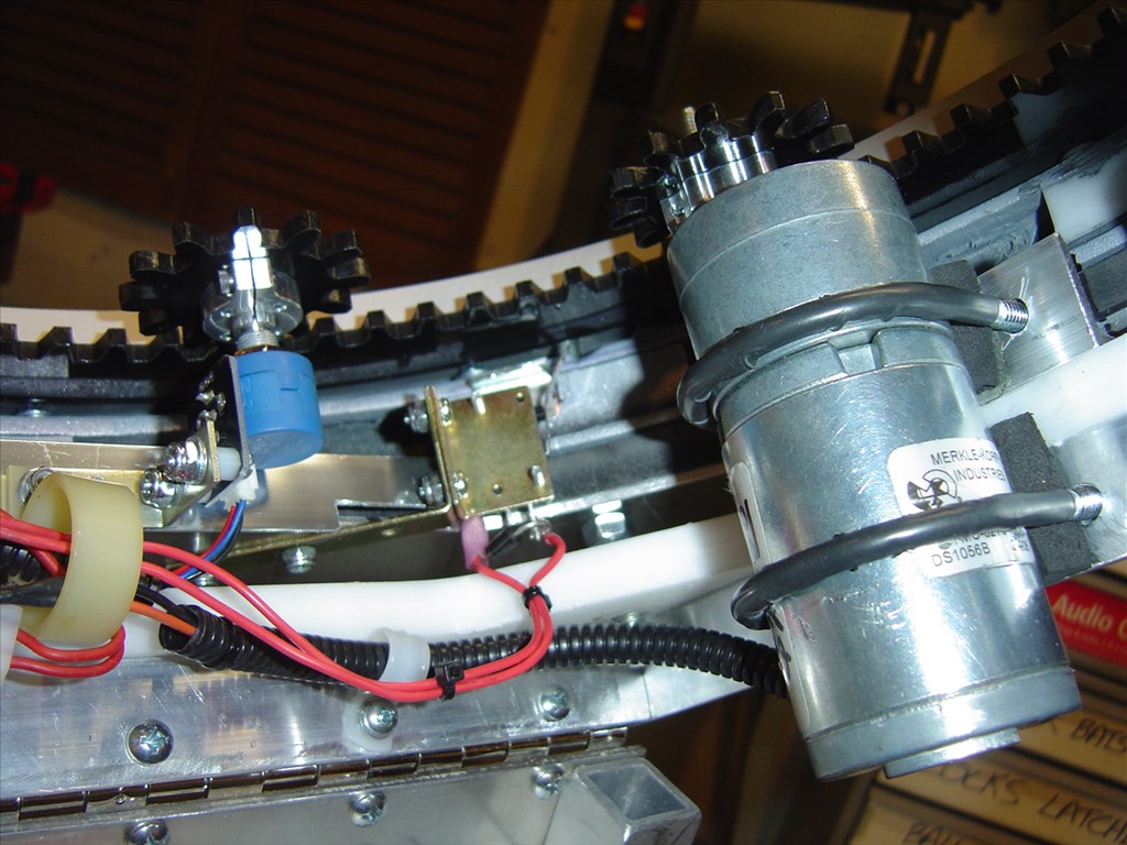
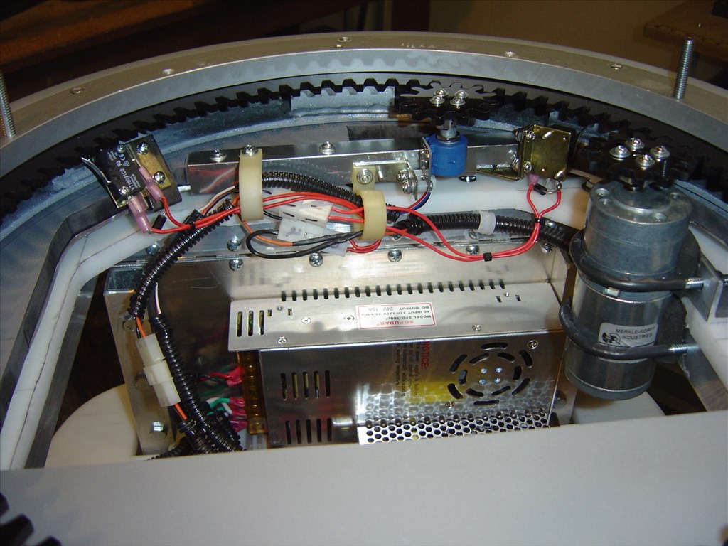
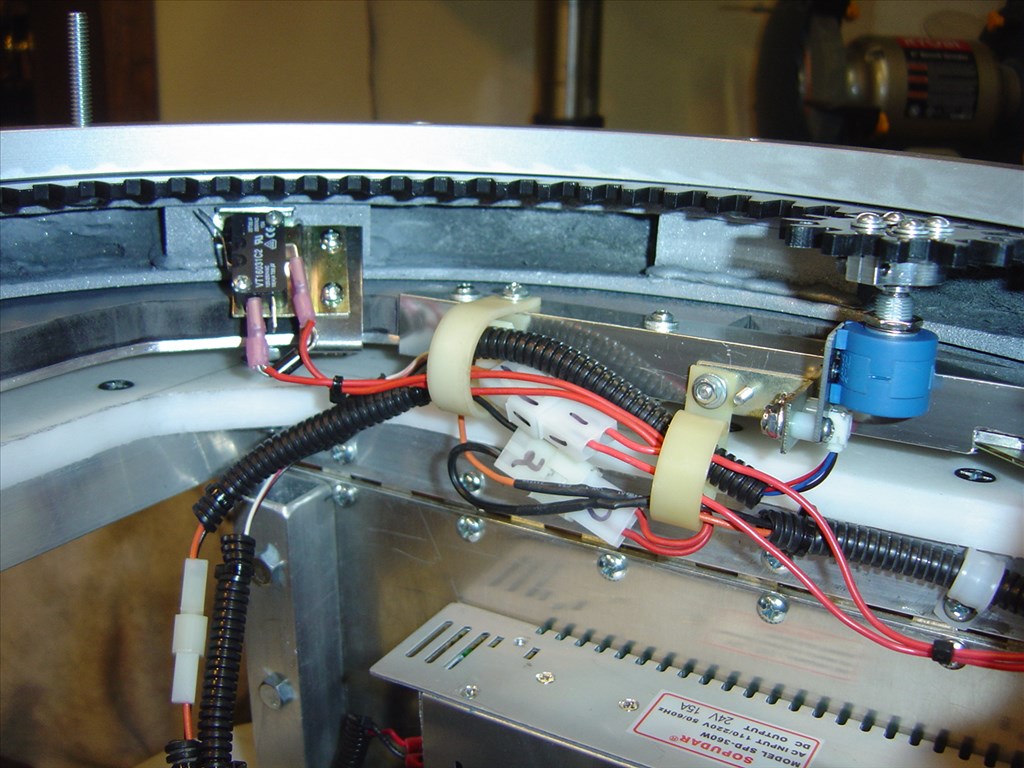
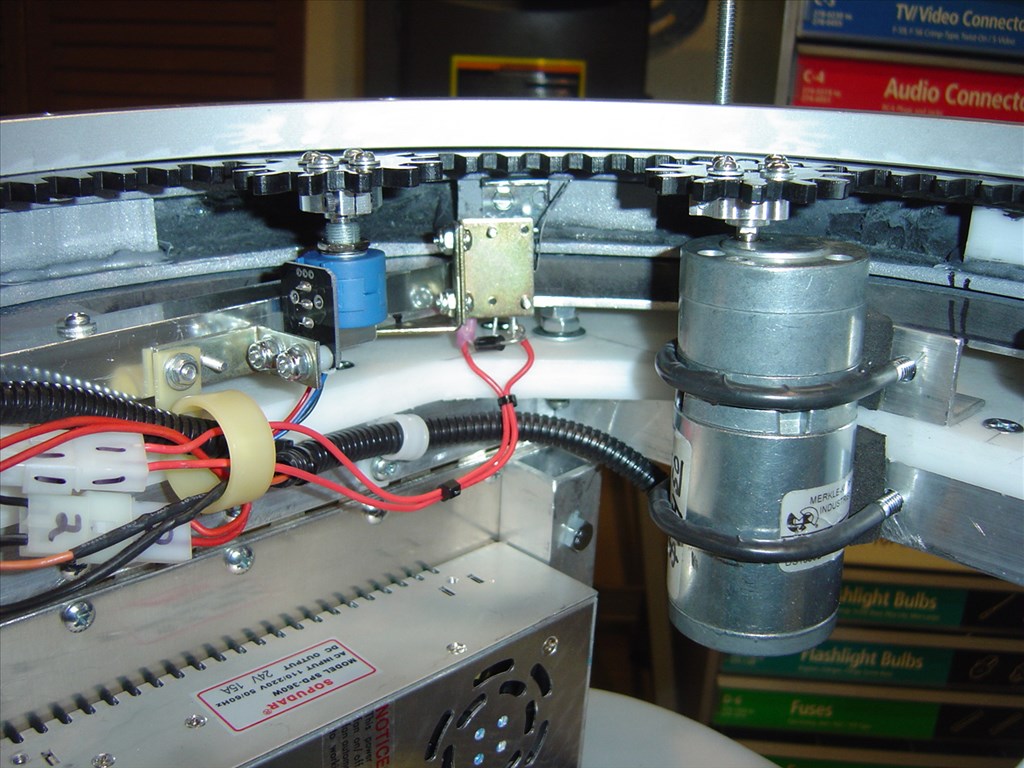
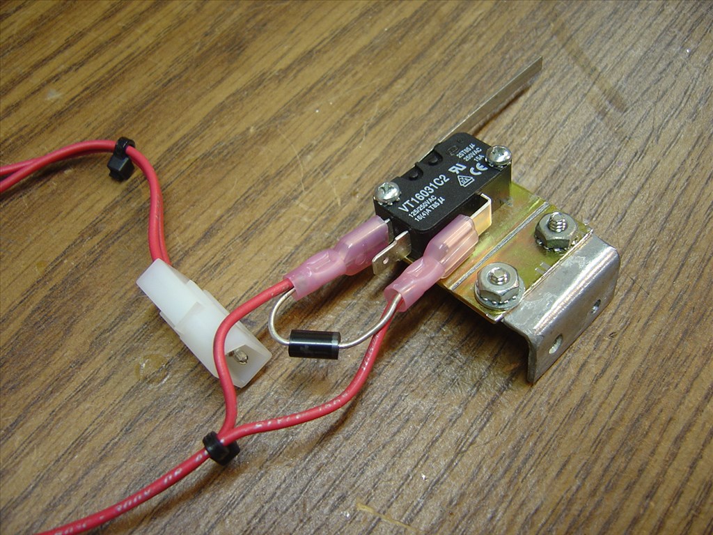
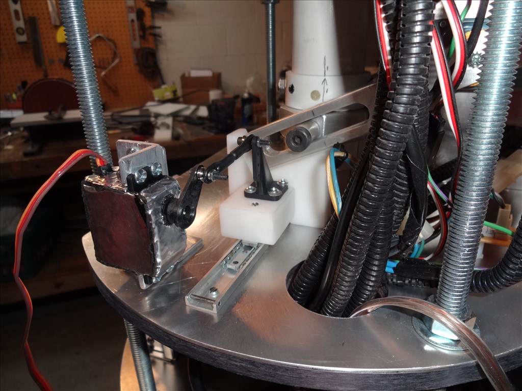
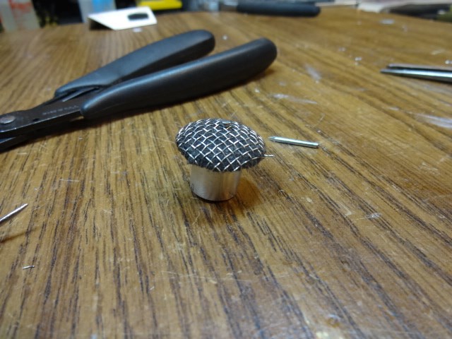
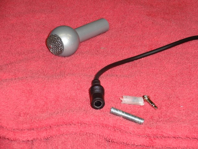
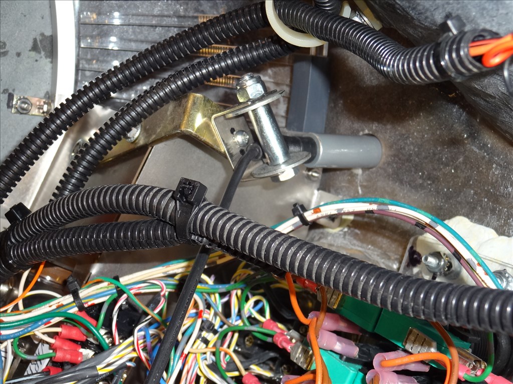
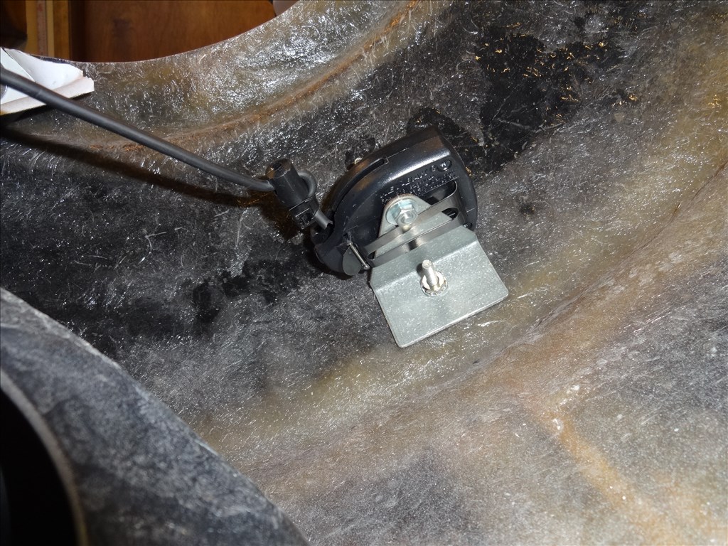
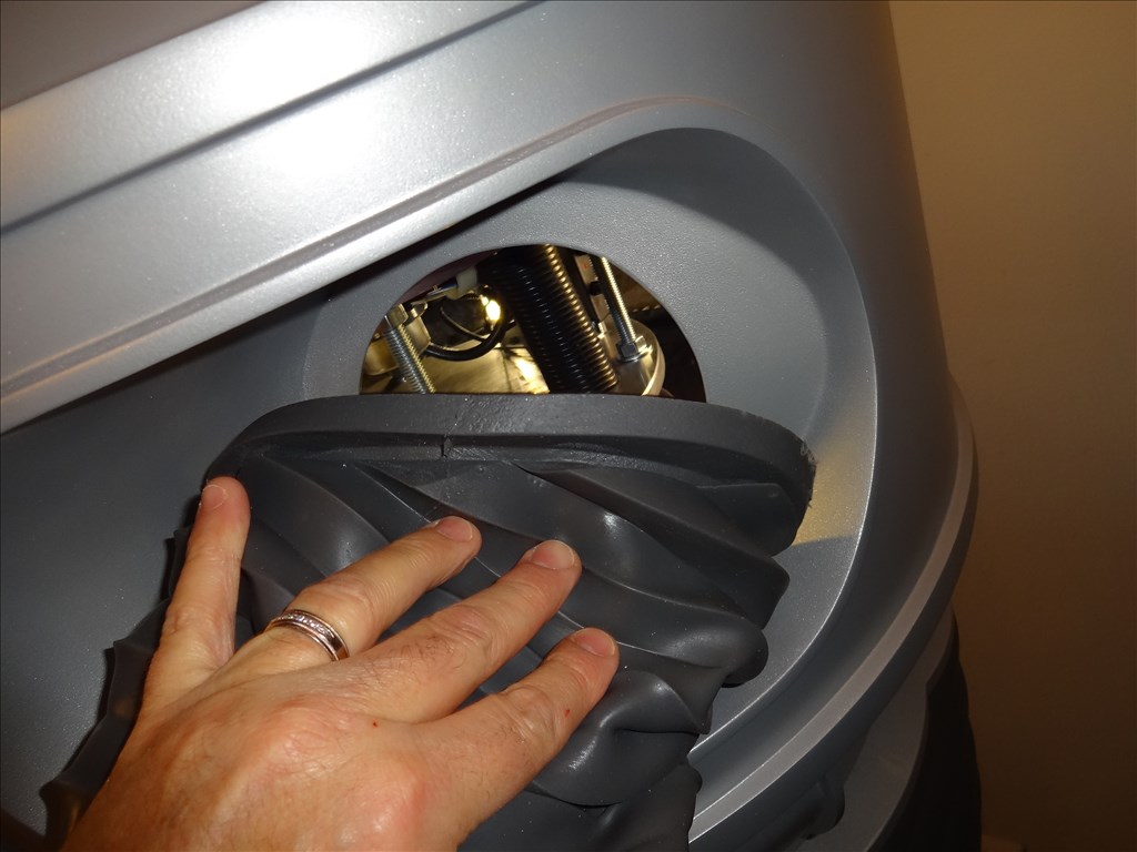
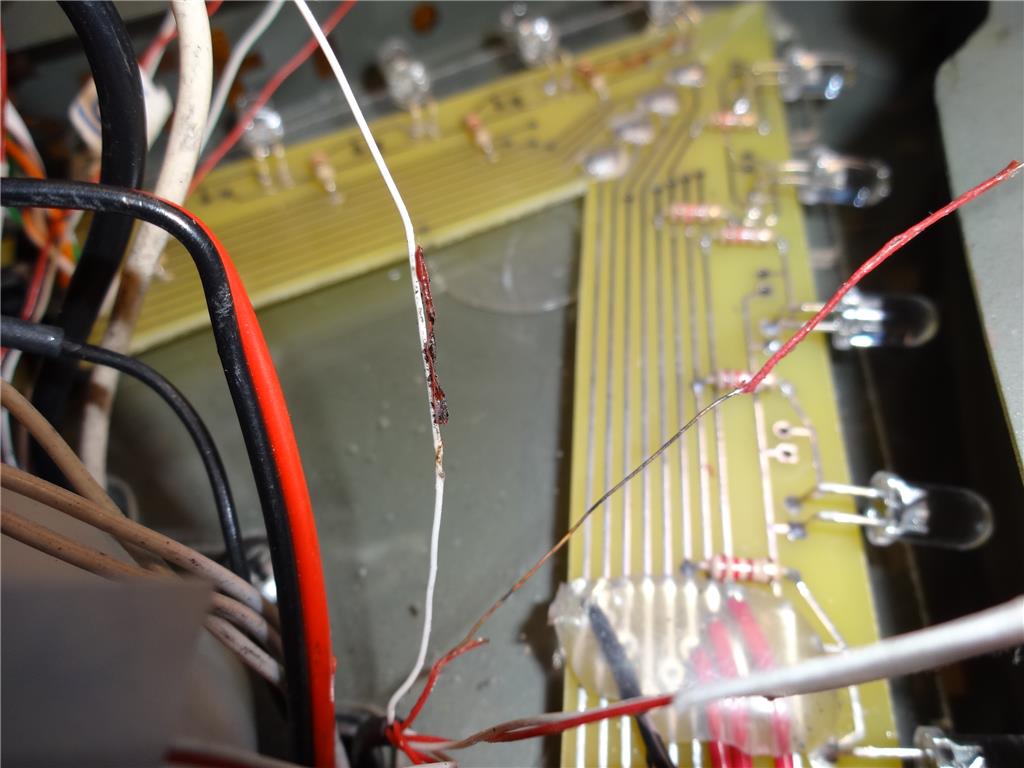
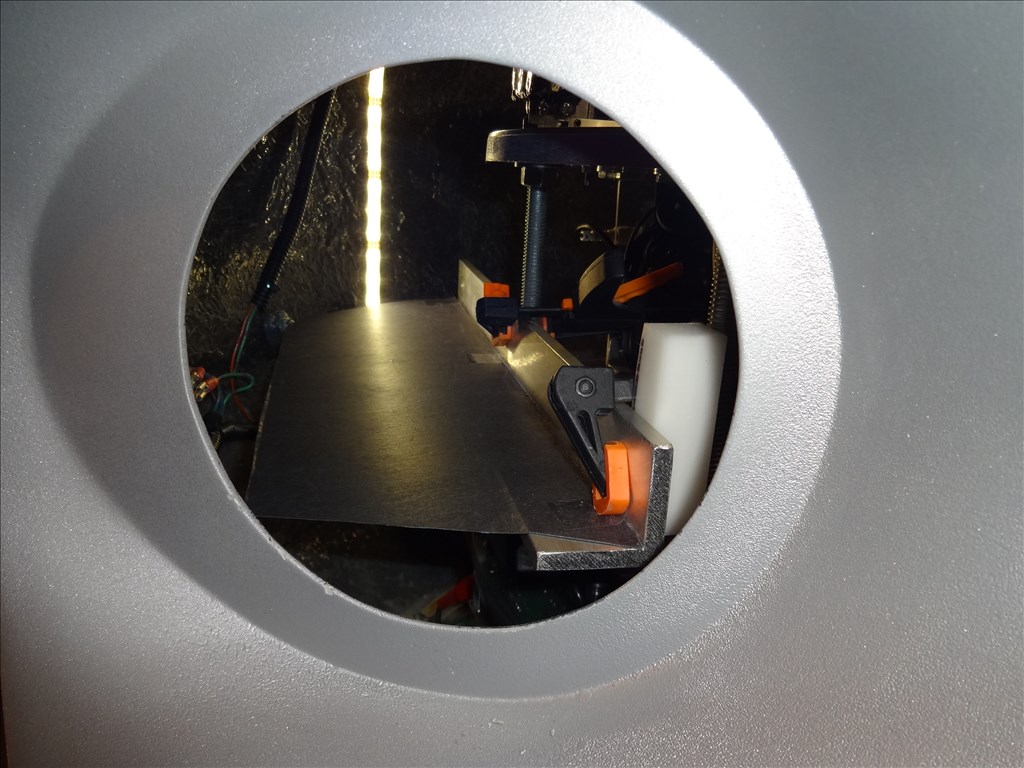
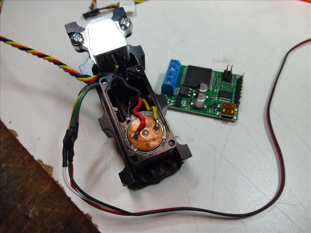
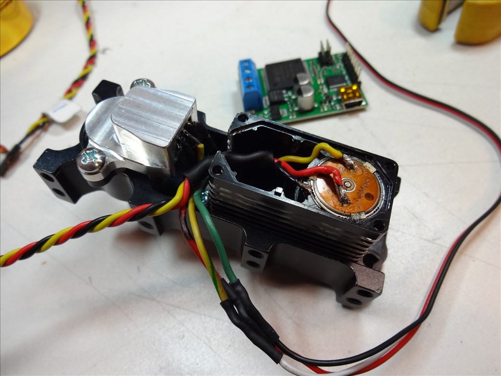
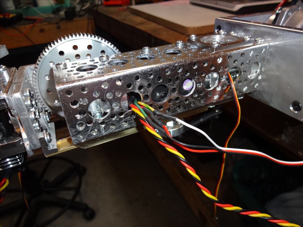
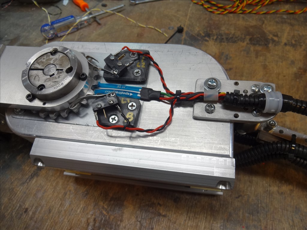
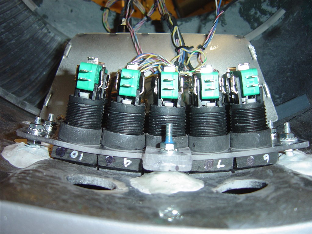
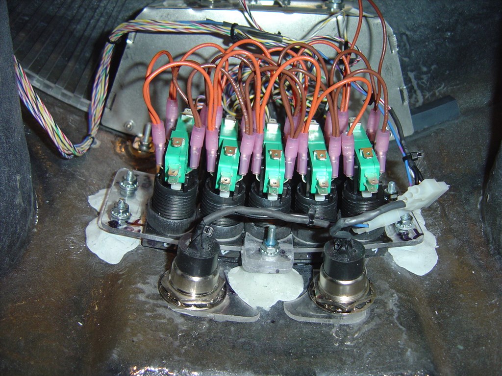
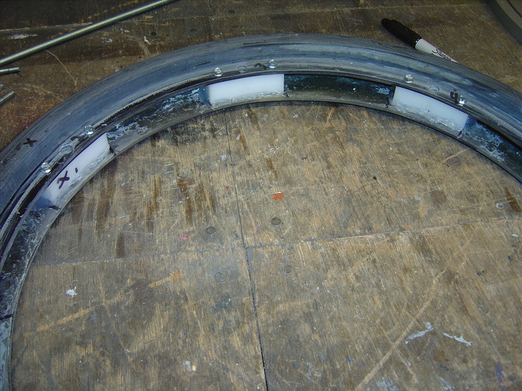
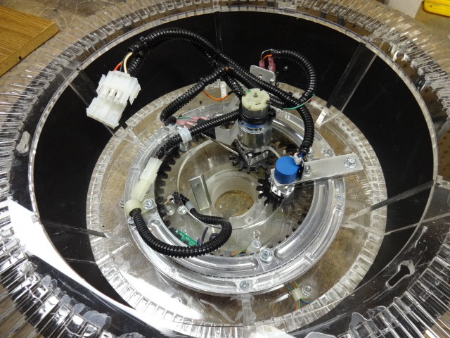
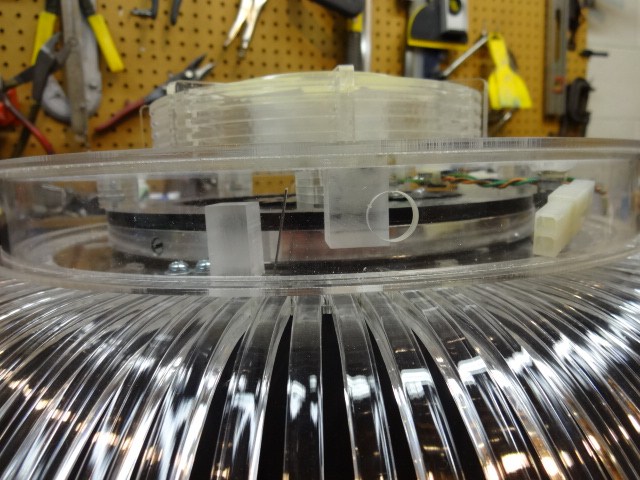
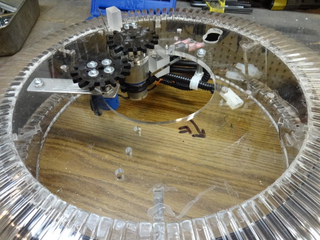
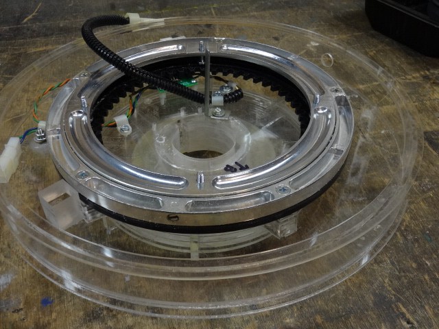
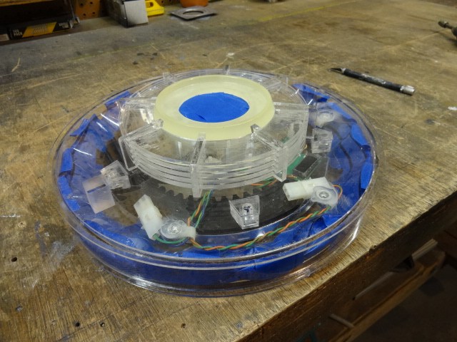
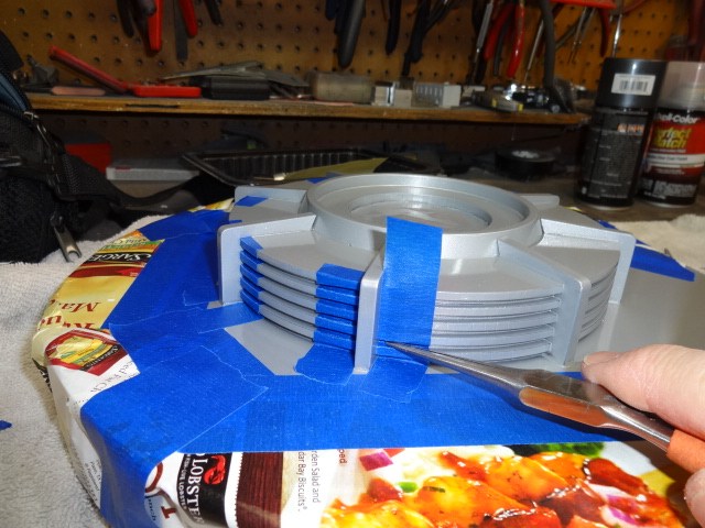
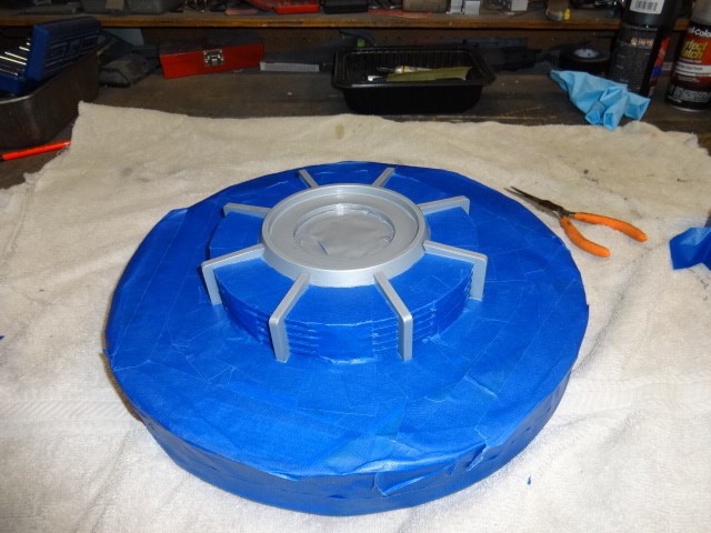
However it's not the opto switch I'm using for my main feedback device. I just installed the opto to help give me a second device to aid with centering. The opto wasn't even on when I was filming this. Sorry for any confusion. I didn't make that clear in the video. I'd prefer using an encoder but I have no room for anything thicker then a half inch if that. The main feedback device I'm using is a Spectra Symbol Rotary Softpot:
@Dave C. I get no movement when I send a second command to center. I think what is happening here is that then I first move to center it's actually within the deadband set in the Kangaroo software. My position in there there is 15mv. When I want to re-position to center the second time I only want to move about 5 or 6 MV so it wont go anywhere because it considers it's self within zero position.
If I close up the deadband anymore the arm acts like a servo trying to find center. It rocks and jerks back and forth trying to center.
Thanks for the input guys. It helps to have support trying to work and think through this. I'm always open to suggestions and help. I've sent tech support to the two manufactures so I'll see what they have to say.
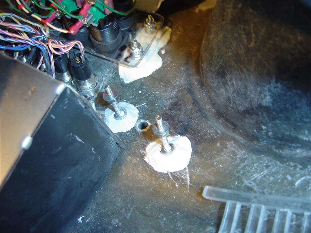
Oh, I think I see now. You were showing the position on the vane which interrupts the opto-switch as a visual reference to show how the arm is not returning to the same point every time. Not indicating that it was the source of positional data.
Well, now that the actual source of the of the millivolts readings you described is the rotary softpot is clear to me (that IS it, right? ) I can do a better analysis. At least a more accurate one. I'll have another look at the video with that in mind before I comment further on the issue.
Just a thought... The problem is the variance of position, to horizontal. The angles to 90 degrees (up and down) gives a shorter moment length at their extremes, less inertia, less weight on the system. At 90 degrees most weight and inertial load, so the PID loop can't react the same in both directions, causing overshoot, or shortage. Deceleration allowing the ramping to zero may help. I forget details of these things but, just an idea.
When I worked on automatic hoist, we had to use brakes, to be able to eliminate this type of thing. Problems with and without loads.
I still hope you can tune this out but a pot may not be able to do it. Flat encoder? More ramping to zero?
Ron R