Ez-rover Mk I

Rich

United Kingdom
robot video thumbnail

I haven't shown off a new robot (other than Revolution ones) for a while so it's time to start a new topic for one of the few I'm currently working on :)
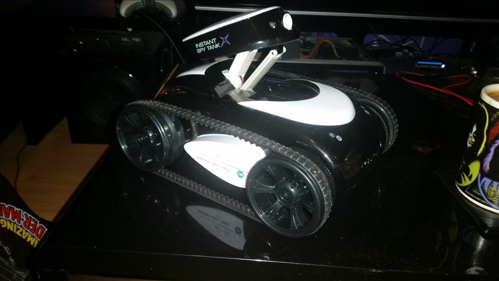
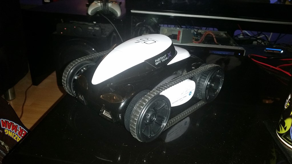
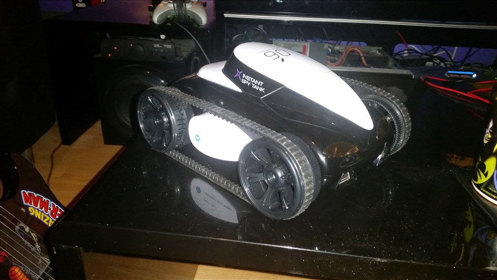
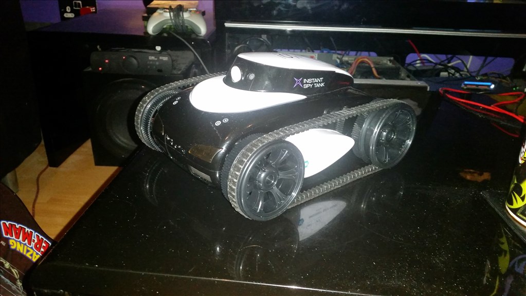
EZ-Rover MK 1

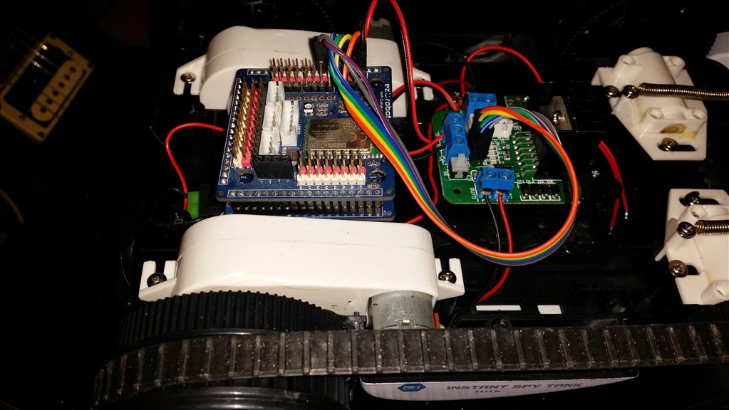
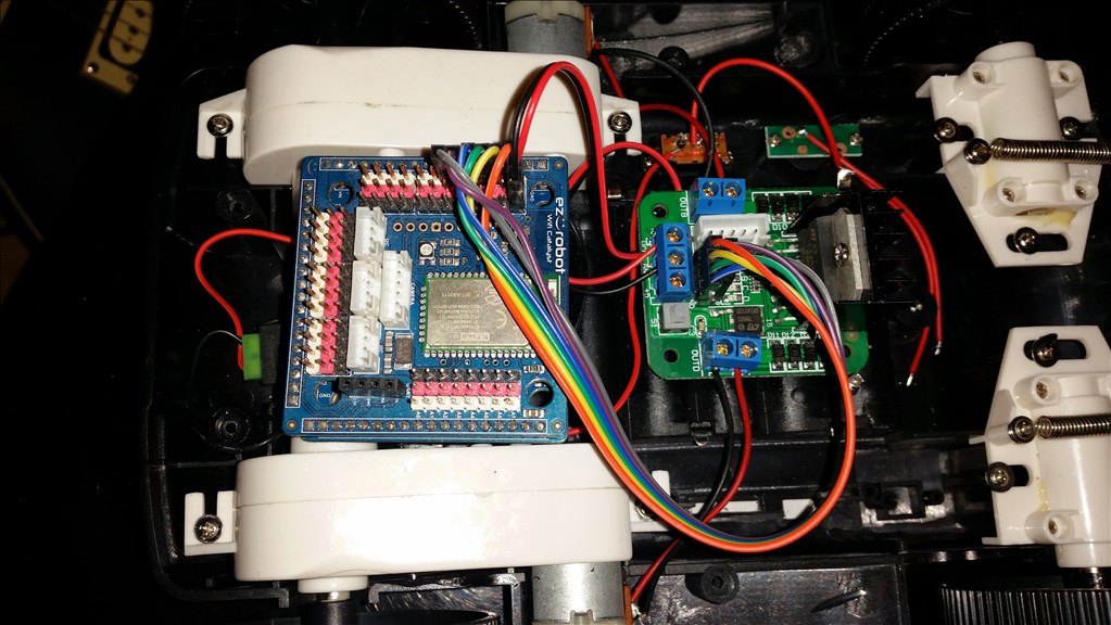
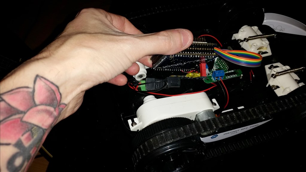
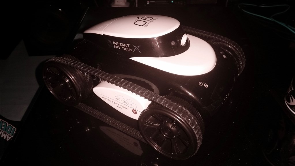
Originally a WiFi controlled tank which looks based on the Brookstone rover. The WiFi was not easily hackable and it was much easier to just gut it and replace the internals for an EZ-B, H-Bridge and EZ-B Camera.

Originally it was run on 6 x AA batteries so I have kept that set up and using the existing moulded battery compartment just wired directly to the EZ-B.

This will be 100% autonomous and it's purpose will be to roam the ground floor of my house.

IR and Ultrasonic sensors will be fitted to it all around (space permitting) and collision avoidance done with a modified version of my ping roam adapted to use multiple sensors rather than a rotating sensor.

More to follow when I open it up again to fit the camera in there.

User-inserted image

User-inserted image

User-inserted image

User-inserted image

User-inserted image

User-inserted image

By — Last update

ARC Pro

Upgrade to ARC Pro

Experience the transformation – subscribe to Synthiam ARC Pro and watch your robot evolve into a marvel of innovation and intelligence.

United Kingdom
#1  

Very nice! It certainly has your Style Rich!

Tony

#2  

@Rich... That pop up hatch in the top, is that servo controlled? Nice, can't wait to se what you do with it... :)

United Kingdom
#3  

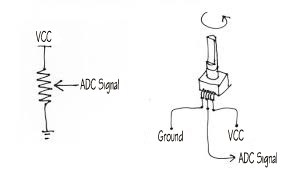
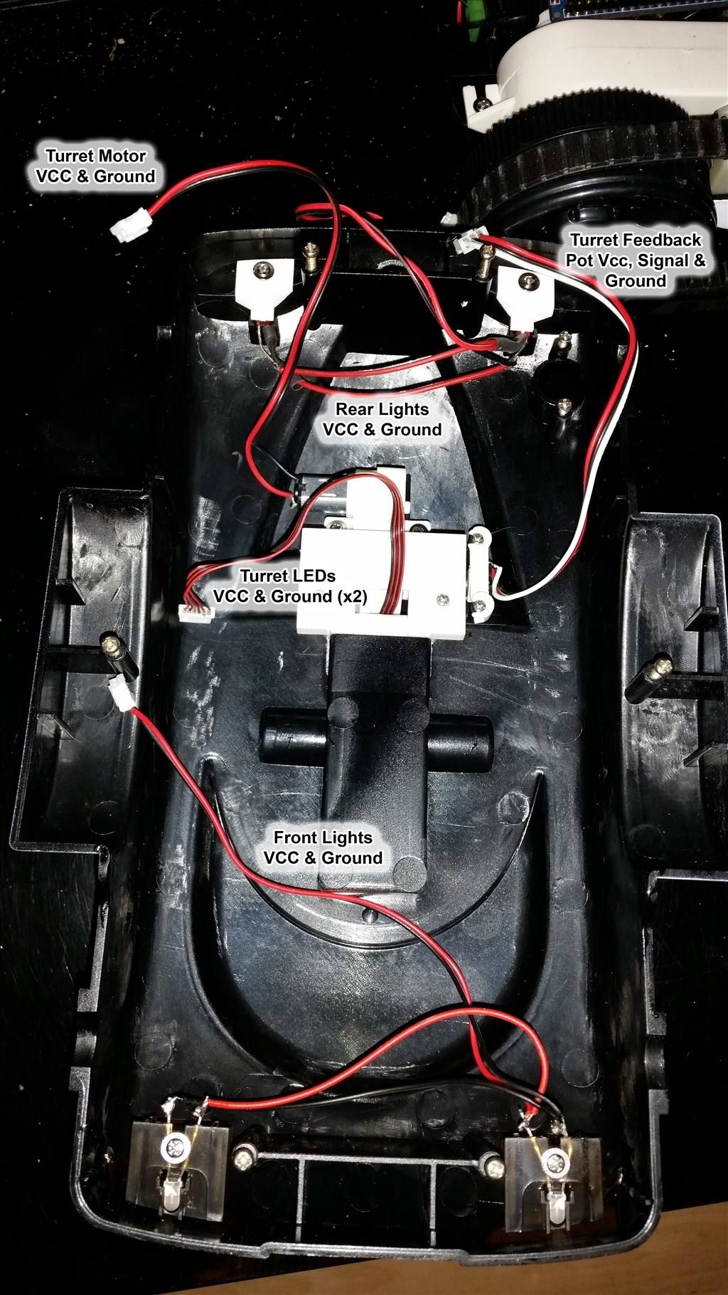
At the moment the original motor is still in there to lift/lower and I'm tempted to keep it there and experiment with some feedback pots or switches, something different and not as straightforward as the easy way (the easy way is best but I like to do things the hard way).

United Kingdom
#4  

@Rich.

From what I know if you, you certainly don't take the easy road. But than, that's what you do. Take something, do it "the hard way" and come up with something fantastic. Besides, things are more interesting when it's a challenge. The rover really does look pretty cool and I really look forward to your progress to what you will achieve with this. :)

#5  

Good Grief Rich, your tank mod is going great so far, think you might use LI packs inside ?

#6  

Rich, I will definitely be following this one..... Can't wait to see how you trick out this bot. Does it have any problems skid steering on carpet? What are you going to use to control the motors?

United Kingdom
#7  

I don't have carpets downstairs so it's not an issue. I will test it on the two carpets (one is a deep shag too) upstairs though at some point.

The original motors in it are controlled by the EZ-Robot H-Bridge with PWM speed control. One of the things I will be working on with this robot is centering down a corridor so speed control is a must.

It's going to remain a pretty basic robot but will be used to test and play around with a whole bunch of controls. Maze solving, object avoidance and navigation using various tracking methods are amongst the top few things on the list.

#8  

@Rich.... I am sure you have already figured out how to navigate the hallway... I used 1 side mounted ping and a front mounted ping on my inmoov so he would stay a fixed distance away from the kitchen island as he navigated around it (in my inMoov video)...

United Kingdom
#9  

A few more photos while I had her opened up :)

User-inserted image

User-inserted image

Using the power board from the power base keeps the fuse and makes connection to the EZ-B simple. User-inserted image

The top of the tank. LEDs for headlights and for tail lights (will be run via a TIP122 circuit). Lift motor for the turret (will be run via a TIP122 circuit) and feedback pot for the turret lift. User-inserted image

I may re-purpose an old servo board and use it to drive the motor and use the feedback pot in place of the servo board's pot - I've not yet tried it but in theory it should work.

#10  

Rich, Lookin good! Can't wait to see this cool bot moving around with all the great ideas and moves you are probably working on! I like all of your details and explanations. Steve S ;)

#11  

Way cool Rich. I look forward to watching this project evolve.

United Kingdom
#12  

A little more progress on this last night but not much time spent really (although more than I'd care to think it took!).

The feedback pot is wired and working on an ADC port of the EZ-B. It sounds simple enough however I have no idea what the designers of the iSpy Tank were thinking when they made this thing but the pot was wired in some very strange way, with cable colours which didn't follow the standard red = live, black = ground.

Turns out that White is ground and Black is the feedback, who knew?! But I could only find this out by removing the turret lifting mechanism (which is so awkward!) and removing the pot and all of the other junk attached to what I presumed was a simple 3 wires to a pot circuit.

Temporarily tapped on to the pot to check it would work and it does so tonight's job is to rewire it with the correct colours to the correct pins.

One thing I did notice is there is very little information on how to wire up a feedback pot on here. Yes, it's simple (and yes I did know how) but for the benefit of giving accurate and clear information for anyone starting out or anyone who just hasn't looked at the electronics involved in feedback pots here is the info... User-inserted image

Jumping off of the project a little here but how this works (since I like to explain stuff)...

Imagine the arrow on the sketch to the left above is the point at which contact is made on the resistive strip. The arrow moves up and down so there can be a varied amount of resistance on either side of the head. This, in essence, is a voltage divider circuit. When the resistance either side of where the arrow is varies the voltage travelling down the arrow to the signal pin varies.

The current remains a constant since the overall resistance from Vcc to Ground doesn't change. R1 (above the arrow) and R2 (below the arrow) will always equal the same R1 + R2 = Rt.

We know that the voltage is also always a constant 3.3v from the Vcc of the ADC pin.

For the purposes of the explanation let's assume the resistance (Rt) of the strip is 1000 ohms.

Ohms law states V = I x R so to calculate the current flow for this (which will become clear shortly) we transpose that to I = V / R or I = 3.3 / 1000 which is 0.0033A or 3.3mA

Now, let's presume that the pot is centred so we have equal resistance either side. R1 = 500 ohms, R2 = 500 ohms, Rt still = 1000 ohms.

We have I (current) at 3.3mA, we have R1 at 500 ohms therefore V = 0.0033(I) x 500(R1) = 1.65v

Now let's say we move the pot, or move the arrow up the strip in the above sketch. Let's say it's 20% from the top. So R1 would therefore be 200 ohms, R2 would be 800 ohms and Rt remains to be 1000 ohms.

We still have I (current) at 3.3mA, we have R1 at 200 ohms therefore V = 0.0033(I) x 200(R1) = 0.66v

Now, let's move it to 90% from the top. R1 would be 900 ohms, R2 would be 100 ohms. Once again, Rt still remains at 1000 ohms.

We still have I (current) at 3.3mA, we have R1 at 900 ohms and therefore V = 0.0033(I) x 900(R1) = 2.97v

As you can see, the closer to one side the pot moves the lower the voltage at the signal point. The closer to the other side, the higher the voltage. This can therefore be picked up within ARC using the ADC controls of GetADC() command which can then be used to start or stop motors or do anything else required.

Back on to the project...

I also spent some time moving the old H-Bridge Movement Panel over to an Auto Position Movement Panel which gives a better container to hold all movement scripts such as the multi-directions for the tracks and the up/down of the turret. This does lack a PWM speed control however so the idea may revert back to the old H-Bridge Movement Panel and a Script Manager but we shall see.

More to come tonight (hopefully).

United Kingdom
#13  

The turret is now back in, the pot wired to an old servo board and the turret motor connected to the servo board also. While it works I think there is still a little work to be done.

Using a vertical servo control on the servo board the results are as follows;

That's not going to cut it! So back to the drawing board.

Update: Turns out this is what happens if you wire the pot up incorrectly... Now it's just a case of reconfiguring the pot wires (which is simple to do without removing anything) the correct way and setting the limits in the control.

It also means the servo board idea worked which means the board from an MG995 which I know can draw over 2A should work to run DC motors on one port per motor as if it were a modified servo! :)

#14  

@Rich... What wiring was wrong? Is the centre pin of the pot not the adc signal? I am also using this method in another project to turn DC motors into basically servos... I did my share of removing the pots from the giant scale servos on my inmoov. This is what gave me the idea that it was easy to turn dc motors into servos....

Thanks for the formulas by the way.... I really should know those...

United Kingdom
#15  

The diagram I posted is right, centre is ADC. But I've changed how I'm doing it, no ADC, just an old servo board to drive the motor using the pot to replace the servo boards pot.

Problem was, I forgot the Red and White cross over on the wire I used to go to the pot (wired for an ADC port not as a direct replacement for a pot) so had those crossed. Now I just need to work out the correct order of the wires on the servo board.

#16  

@Rich Gottcha'... The reason I asked is in my inmoov the external pot wiring must be reversed in his left shoulder servos when compared to his right.... In all you have o modify about 10 large servos for the inmoov... Like you with the H-bridge, it got to the point that when I flipped the servo boards over to solder the new pot wiring I knew by heart what colour wires to solder to what board tracer junction. Ok, it was only 3 wires. What I mean is I can do it in my sleep now... :)

#17  

I've got a noob question. I have Brookstone Rover (both a 1.0 and 2.0). Can I buy the EZ-bv4 and simply replace all the controller boards? That is, can the EZ-bv4 control the motors that are in the Rover without any modifications? And how about the camera , can the bv4 get video from it?

If bv4 can use the existing motors, that's great. The camera is awful, so replacing it with EZ-Robot camera is fine by me.

Thanks for info.

#18  

@dr_glenn Yes, but you may need an H-bridge motor controller if there isn't one built into your Rovers... It's easier just to use the ezb4 camera

United Kingdom
#19  

If the camera will fit then swap it out for the V4 one. I doubt you will be able to get the original camera feed if you gut the rover.

As far as replacing the guts for the EZ-B and driving the existing motors, that is exactly what I have done with this one. The insides will probably vary but provided there is space then sure, it'll work.

I've covered most of what's in my rover in earlier photos but will provide complete information in clear and descriptive explanations when it's done.

The short answer is yes you can. You will need to check on space inside the robot and make sure the EZ-B fits in there with the accessories (h-bridge etc) plugged in to the digital ports. I need to adjust the layout of mine as I found the front 12 ports do not allow for connection with the top of the rover fixed on but it will all fit in with some playing around.