
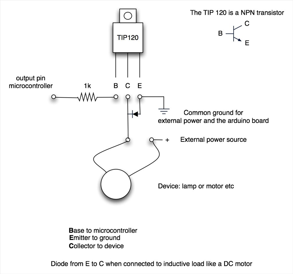
Tip120 & Tip122 Transistor Switching Circuit
I just decided to redo one of my TIP122 Transistor Switching Circuits (mainly because I needed a break from working - there is nothing wrong with the 2 that are already in my Hearoid). So now's as good a time as any to do a small tutorial
This has become an evolving tutorial with additional information and options available being added. The change log at the end of this post explains changes made. Any additional information will be added as and when discovered.
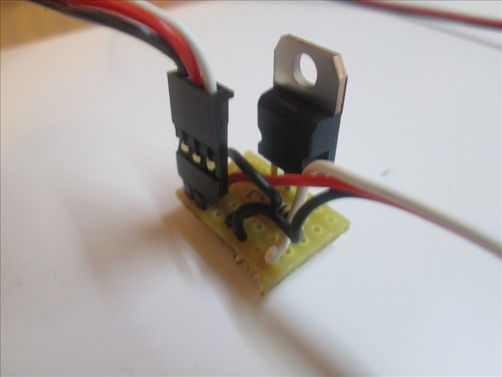
Parts needed: 1 x TIP120 or TIP122 Darlington Transistor or IRL3103PBF Mosfet (see notes at the end) 1 x 1k ohm Resistor 1 x Small Piece of Strip Board (7x5 holes) 1 x Pin Header (1x2) 1 x servo Extension Solder Soldering Iron Cutters
Extra parts needed (if inductive load): 1 x 1n400x Diode as required
Search for part numbers in google or ebay or use your preferred supplier.
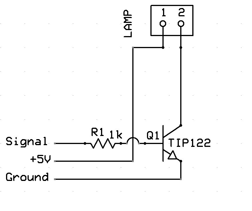
The Schematic:
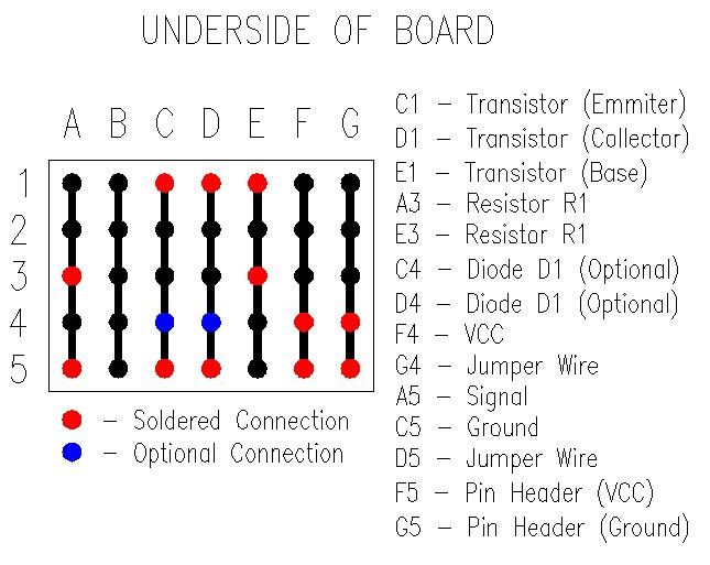
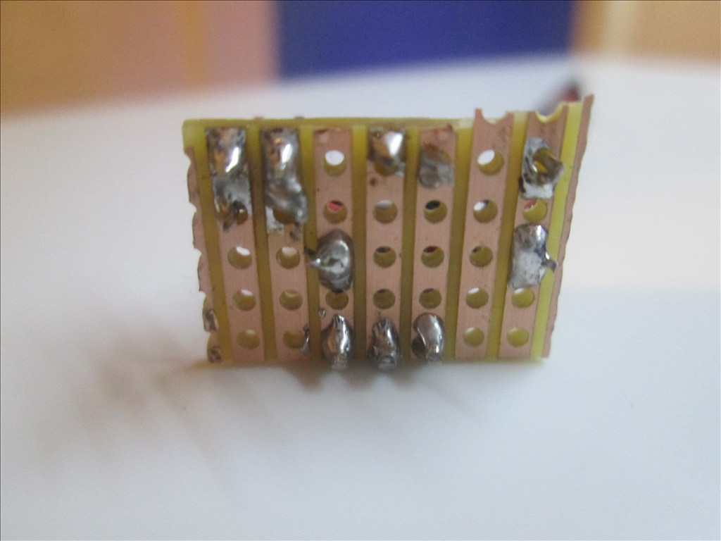
Underside of Board:
Method:
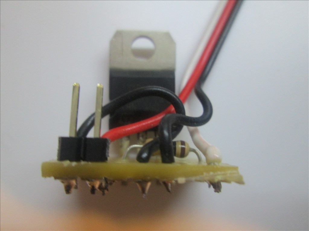
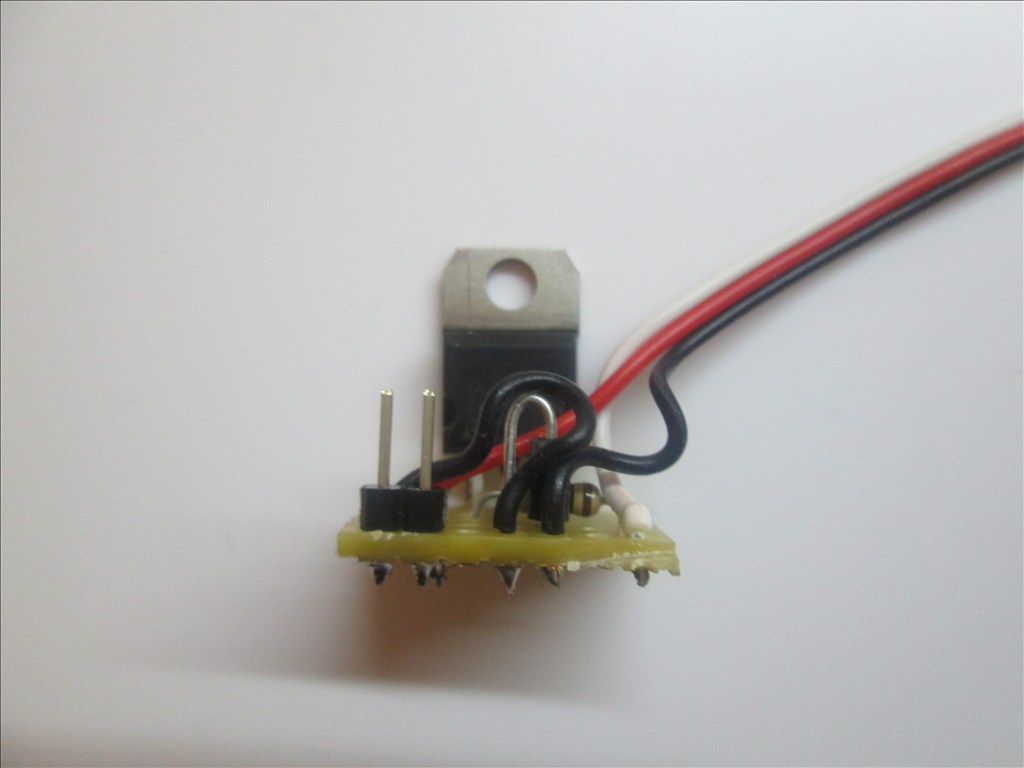
Solder the TIP transistor to the strip board so each pin is on a separate strip of copper

Solder the resistor from the Base of the transistor to a spare copper strip
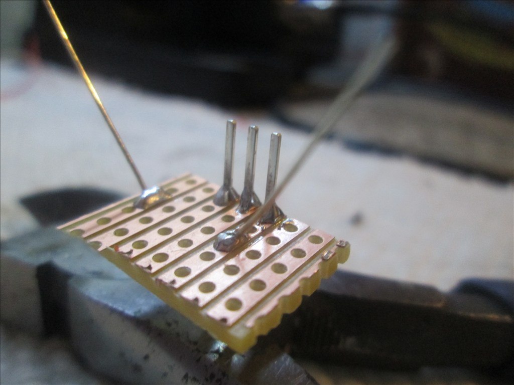
Cut off the end of a servo Extension and strip back the wires
Solder the Black wire of the servo Extension to the strip connected to the Emitter of the transistor
Solder the White wire of the servo Extension to the strip connected to the end of the resistor (not the transistor end)
Solder the Red wire to a spare copper strip
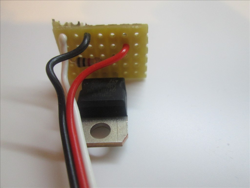
Use a small off cut from the servo Extension and solder one end to the strip of the Collector of the transistor
Solder the other end of the off cut to a spare copper strip next to the Red wire.
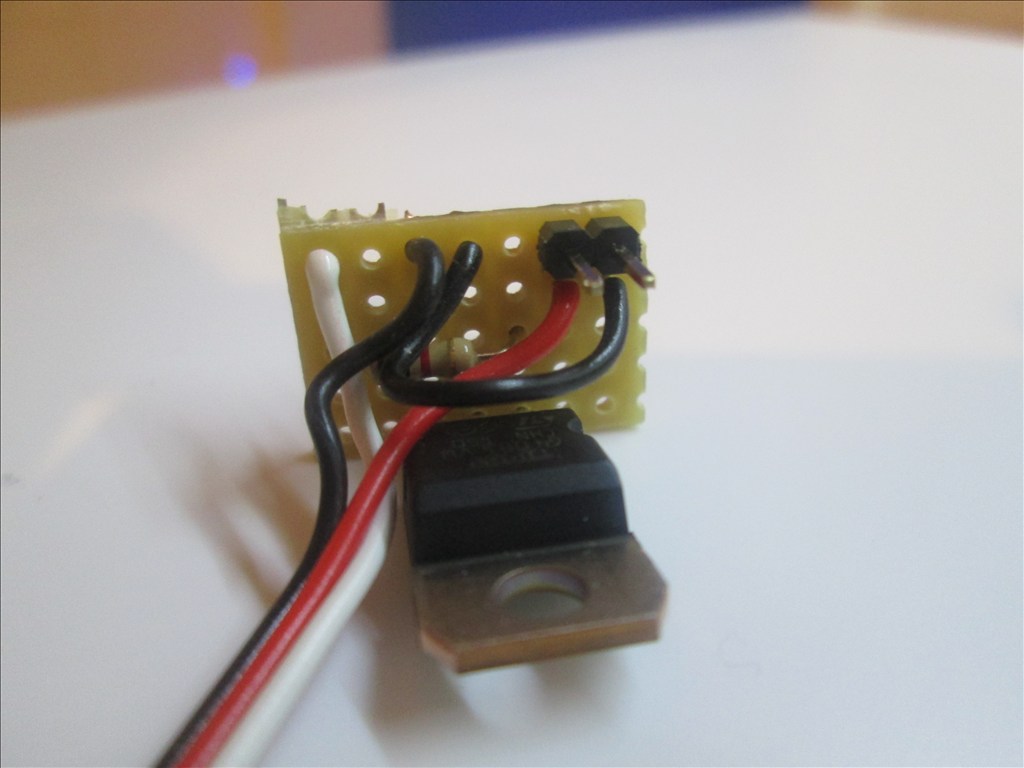
Solder the Pin Header to the copper strips with the red and black wires soldered
Job done. Plug the servo Extension in to a Digital port on the EZB and connect the circuit that needs switching to the Pin Header, I do this with another servo Extension (as I have hundreds of them)
Or a JST connector works very well also
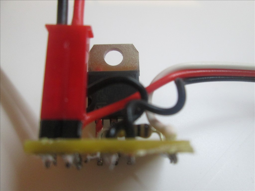
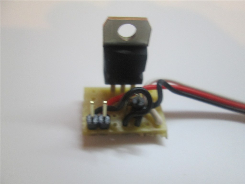
Adding the Diode If using the circuit for a motor or other inductive load a diode needs adding between the transistor Collector and Emitter. This is easily added in to the above circuit.
Bend the leg on the Diode so it will fit though 0.1" hole spacing
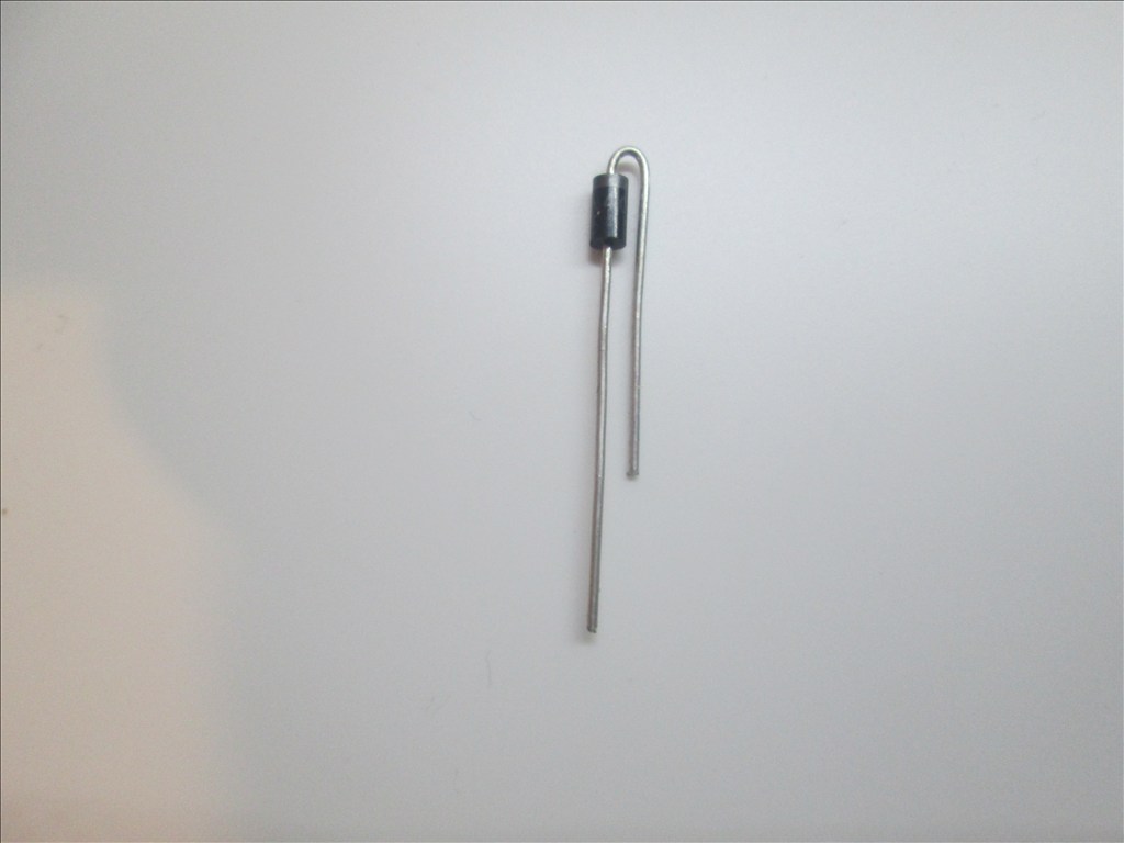
The band on the diode is to connect to the Collector and the other end to the Emitter. It will drop in to two spare holes.
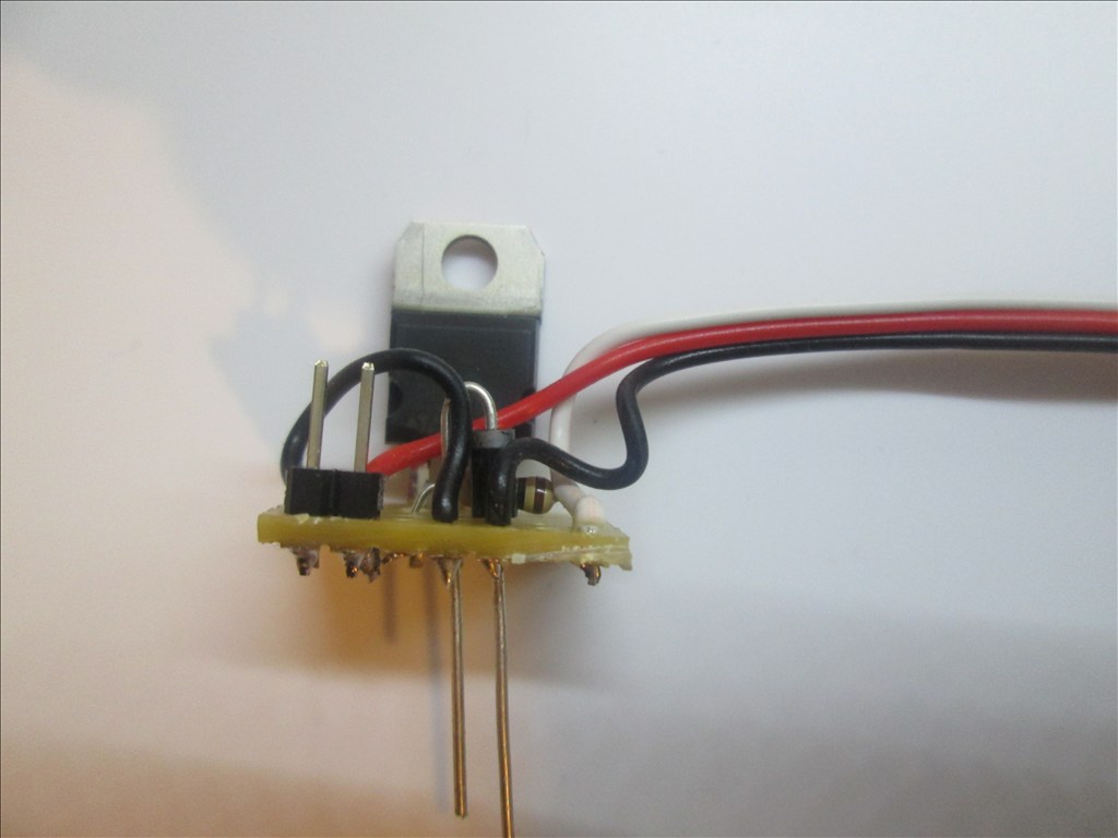
Solder in place and cut off the excess legs.
All done. You should have something like this.
Additional notes You may also use a Mosfet for this switching circuit. A IRL3103PBF mosfet can replace the TIP120/122 Darlington transistor. The circuit is the same however the pins on a Mosfet are named Gate, Drain and Source. The mosfet fits in the same place as the Darlington with the Gate to the left (replacing the Base of the Darlington).
Updates:
Edit 1 (2013.03.07): Underside of board diagram added.
Edit 2 (2013.03.07): For some circuits a diode is needed as shown in the first schematic. The board here does have space for a diode (C4 to D4 - would have to be with legs bent to accommodate 0.1" spacing) however I have not shown one - watch this space
Edit 3 (2013.03.07): Underside of board optional connections for D1 added.
Edit 4 (2013.03.07): Added diode information.
Edit 5 (2013.03.18): Added IRL3103 Mosfet information.

Rich, the picture you have there looks like a resistor not a diode. This is important because a diode picture will show you a band on one end and which direction it would go.
Edit: woops sorry, I see you haven't added it yet. Sometimes it's hard to see things on a little smart phone. I just built one of these circuits yesterday and it works great.
Dave, you misunderstand (perhaps I was not clear that I was showing the picture which needs updating).
I am unsure about the exact positioning of the diode and was asking for advice. I believe I was incorrect initially, rather than replacing the red jumper wire it needs to go from ground to live, so in parallel with the 2pin header on the next row, or a couple of rows up.
I'll make all this clearer later when I get home and have the correct software to make the changes.
@dave, what did you put on the underside to avoid shorts etc.? If anything?
Personally I used the one made in the photos on my Larson Scanner and used hot glue to insulate the underside of the board. Just interested in other options available really.
I actually just did mine on the FET itself. Put wire shrink on each connection, then a large piece on the entire thing. Then I just hot glue it where ever I want. But I like the idea of being able to add diodes and such like yours. Hmmmmm - perf board... I may have to give that a try.
That's how I originally did mine but I wanted something that was a little more re-usable (and had some spare stripboard and spare time on my hands)
So adding the diode across like this?.. If the diode is needed of course.
I'm sorry rich but I can't make it out where your red jumper is going to be in your picture. You need to have the diode installed so that the band is facing the center leg of the transistor. It then needs to be soldered somewhere between that leg and 1 of the leads of the motor or lamp. The other side of the diode needs to go to the right leg of the transistor. Then a jumper goes from that leg to the ground on both your power source and EZB. The left leg of the transistor goes through your resistor and to the digital signal pin of the EZB.
As far as insulating the back of the board, I like to use standoffs. It keeps the board away from the service and looks professional. However I have cut small pieces of thin plastic and attached the board to it with double sided foam tape. Then I either use more foam tape to attach the assembly down or hot glue. Velcro works nice too.
And what does this diode do for the circuit? I am unsure of what it would be used for....thanks.