Tip120 & Tip122 Transistor Switching Circuit
I just decided to redo one of my TIP122 Transistor Switching Circuits (mainly because I needed a break from working - there is nothing wrong with the 2 that are already in my Hearoid). So now's as good a time as any to do a small tutorial
This has become an evolving tutorial with additional information and options available being added. The change log at the end of this post explains changes made. Any additional information will be added as and when discovered.
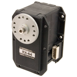
Parts needed: 1 x TIP120 or TIP122 Darlington Transistor or IRL3103PBF Mosfet (see notes at the end) 1 x 1k ohm Resistor 1 x Small Piece of Strip Board (7x5 holes) 1 x Pin Header (1x2) 1 x servo Extension Solder Soldering Iron Cutters
Extra parts needed (if inductive load): 1 x 1n400x Diode as required
Search for part numbers in google or ebay or use your preferred supplier.
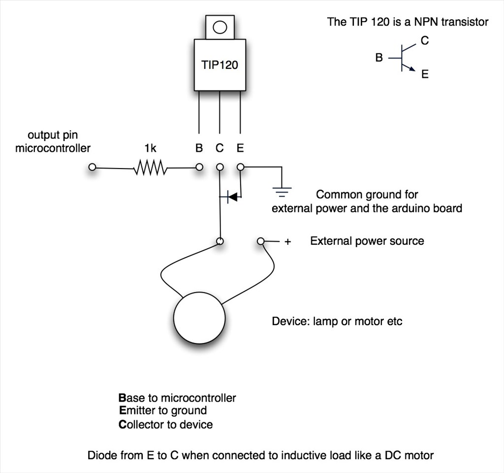
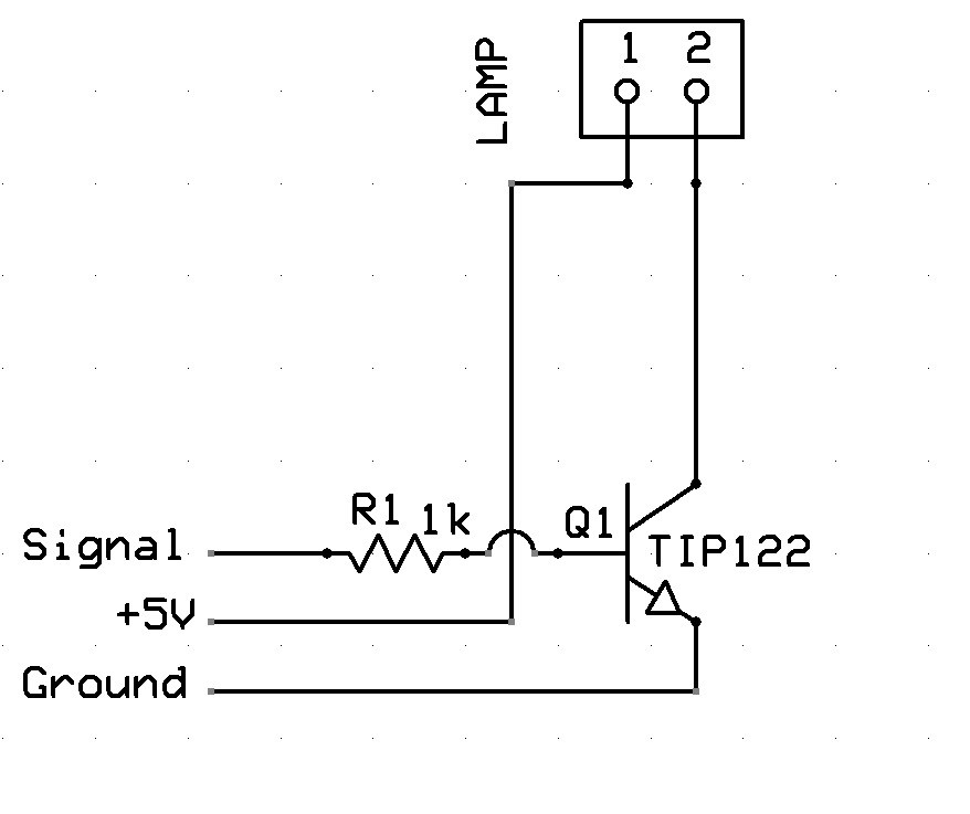
The Schematic:
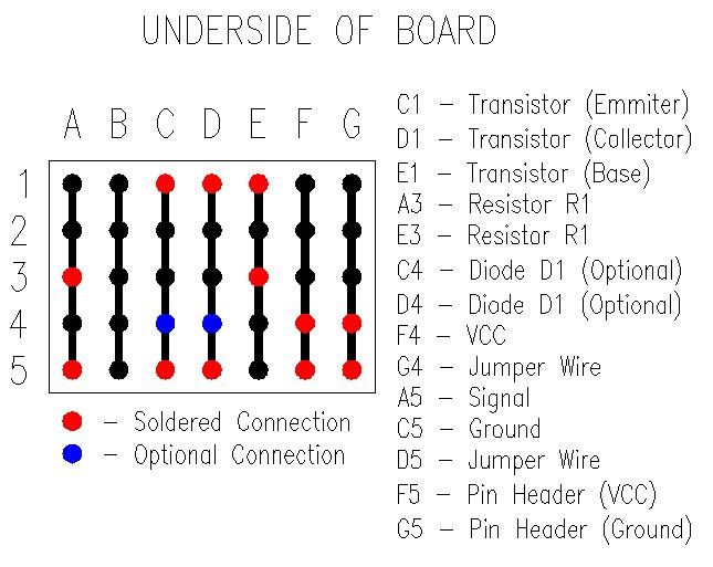
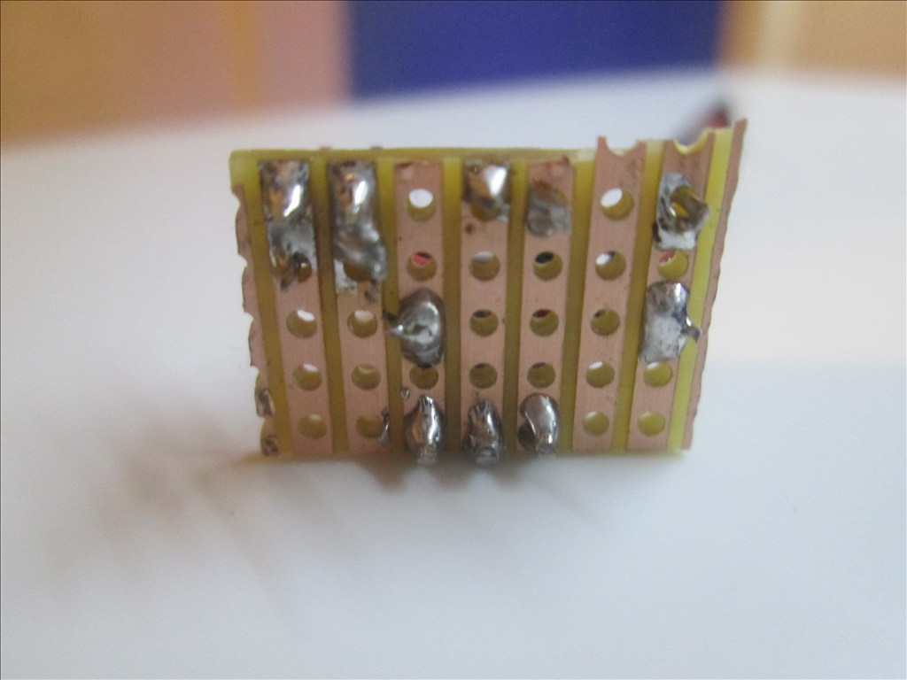
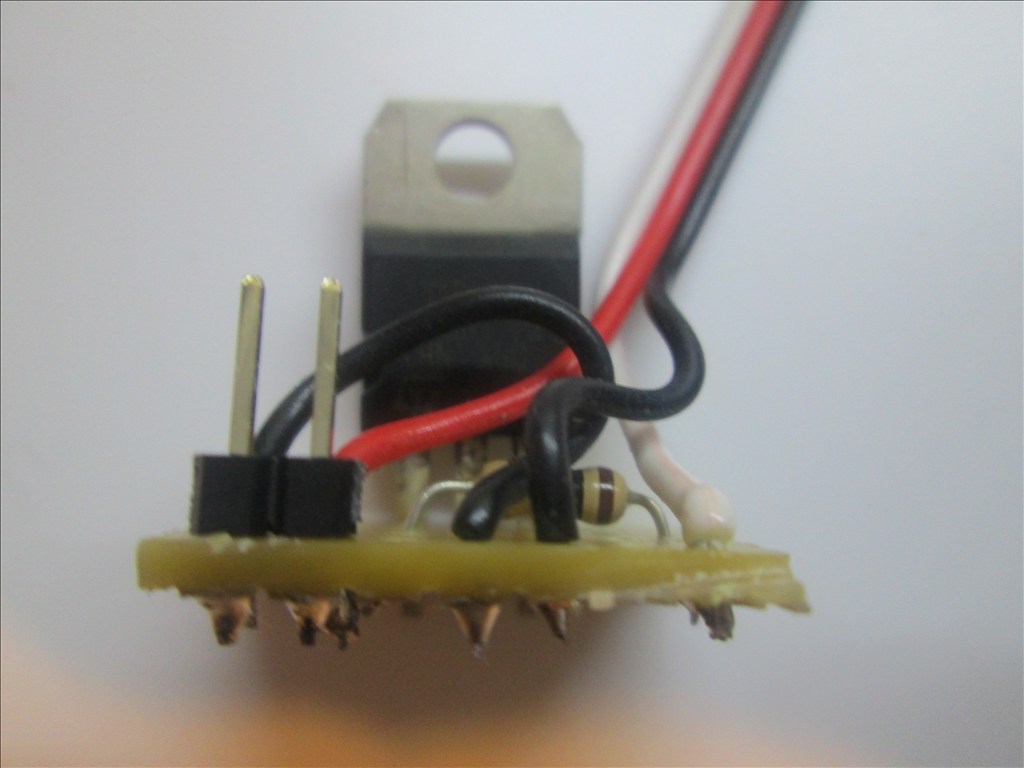
Underside of Board:
Method:
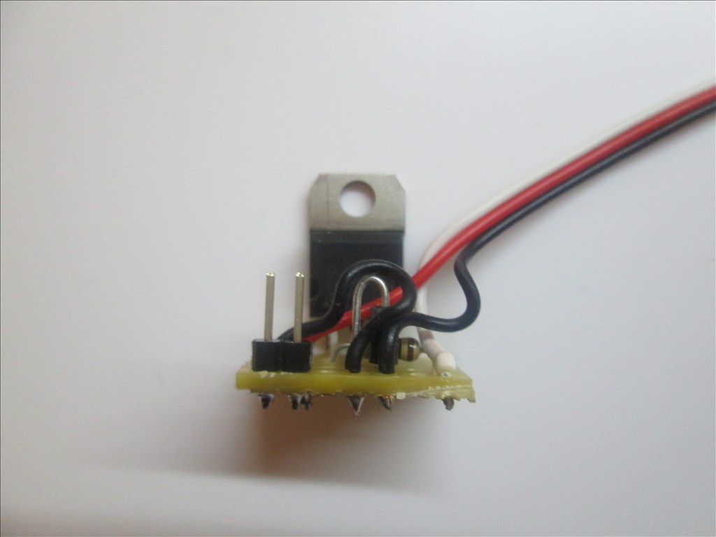
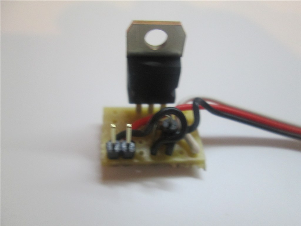
Solder the TIP transistor to the strip board so each pin is on a separate strip of copper

Solder the resistor from the Base of the transistor to a spare copper strip
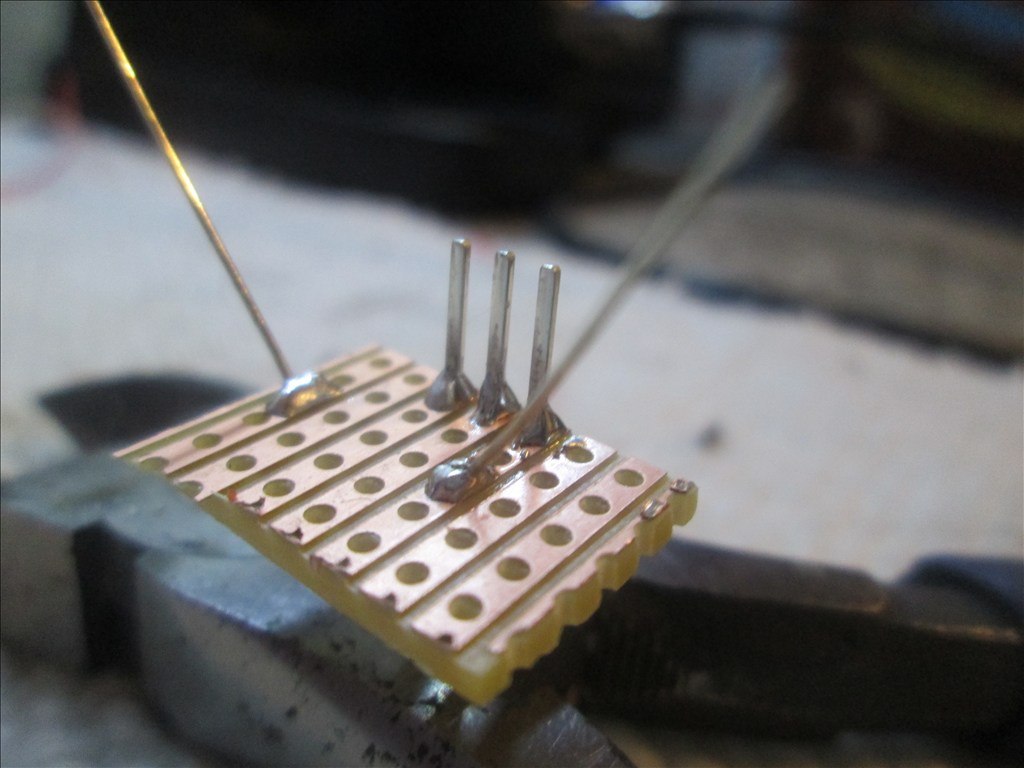
Cut off the end of a servo Extension and strip back the wires
Solder the Black wire of the servo Extension to the strip connected to the Emitter of the transistor
Solder the White wire of the servo Extension to the strip connected to the end of the resistor (not the transistor end)
Solder the Red wire to a spare copper strip
Use a small off cut from the servo Extension and solder one end to the strip of the Collector of the transistor
Solder the other end of the off cut to a spare copper strip next to the Red wire.
Solder the Pin Header to the copper strips with the red and black wires soldered
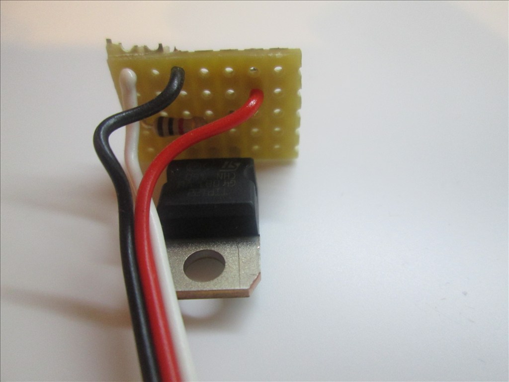
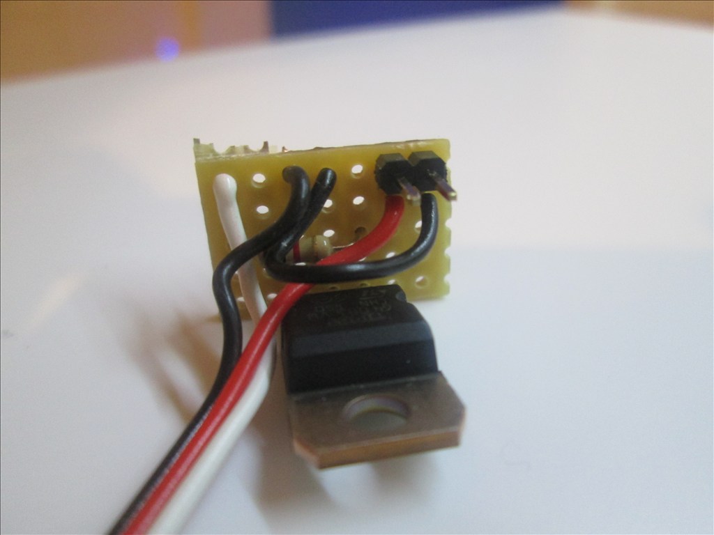
Job done. Plug the servo Extension in to a Digital port on the EZB and connect the circuit that needs switching to the Pin Header, I do this with another servo Extension (as I have hundreds of them)
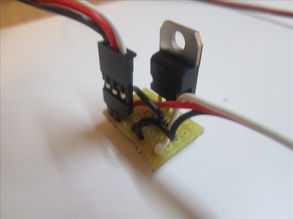
Or a JST connector works very well also
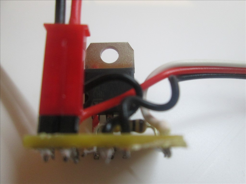
Adding the Diode If using the circuit for a motor or other inductive load a diode needs adding between the transistor Collector and Emitter. This is easily added in to the above circuit.
Bend the leg on the Diode so it will fit though 0.1" hole spacing
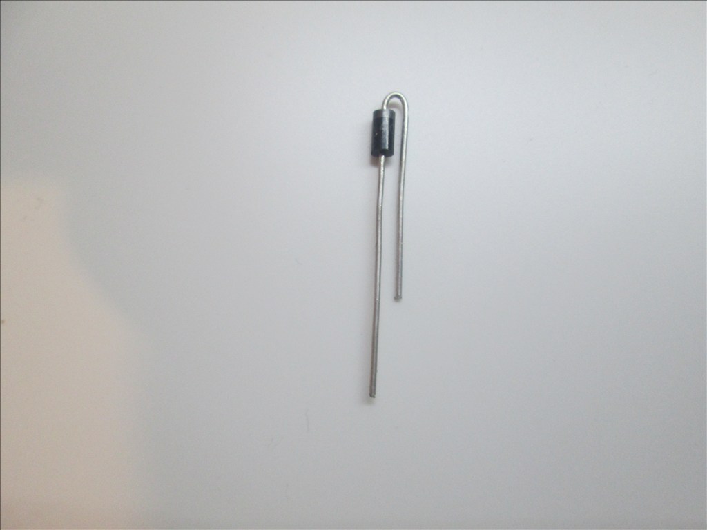
The band on the diode is to connect to the Collector and the other end to the Emitter. It will drop in to two spare holes.
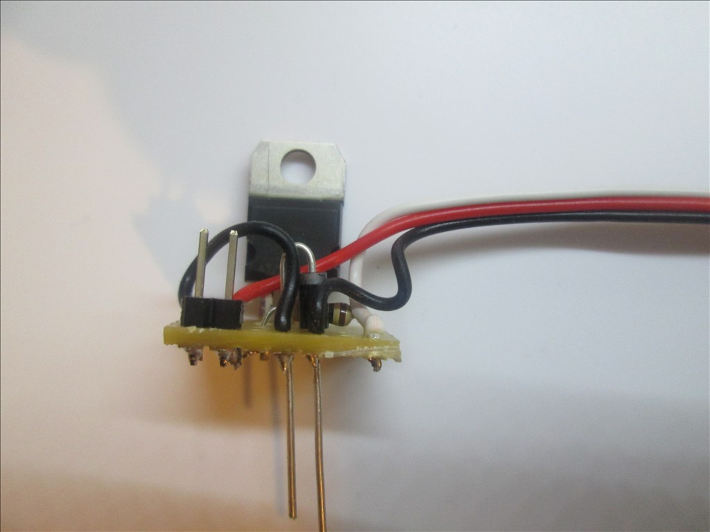
Solder in place and cut off the excess legs.
All done. You should have something like this.
Additional notes You may also use a Mosfet for this switching circuit. A IRL3103PBF mosfet can replace the TIP120/122 Darlington transistor. The circuit is the same however the pins on a Mosfet are named Gate, Drain and Source. The mosfet fits in the same place as the Darlington with the Gate to the left (replacing the Base of the Darlington).
Updates:
Edit 1 (2013.03.07): Underside of board diagram added.
Edit 2 (2013.03.07): For some circuits a diode is needed as shown in the first schematic. The board here does have space for a diode (C4 to D4 - would have to be with legs bent to accommodate 0.1" spacing) however I have not shown one - watch this space
Edit 3 (2013.03.07): Underside of board optional connections for D1 added.
Edit 4 (2013.03.07): Added diode information.
Edit 5 (2013.03.18): Added IRL3103 Mosfet information.

For anyone interested I just threw a PCB layout together for this in ExpressPCB. I've filled their miniboard size so it's $75 plus shipping for 2 boards which would house 12 of the circuits each. I have assumed their boards can be cut easily with a hacksaw.
The layout includes the position for the optional diode across the load, as taken from @robotmaker's links. This is an optional component and is only required for inductive loads.
If people are interested in using one it may pay to do a group buy to bring down costs.
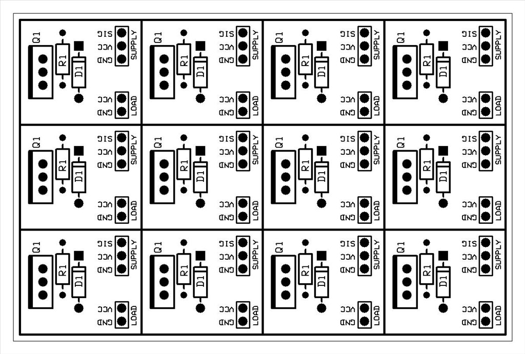
Sorry, ExpressPCB removes the tracks on export.Source files attached for if you want to place any orders or even modify the board to suit your needs. tip.zip
I did the same when i made a sensor board ,where it would have many boards on one sheet
RICH is a good idea only thing i see missing is holes to mount it ,is the only thing i would add.
ONLY other part would be the shipping from UK to usa and would need to have a lot of boards made to reduce the cost.
HOM much would you charge for shipping
IF you read about the inductive kickback ,ITS very high voltage because it acts like flyback. I guess you dont how a flyback works.
On turning on restance loads you dont have that problem.
Useless post, please ignore.
Here is a board about your size i bought about 500 and sold all of them,and some to moviemaker in this forum
As you can see it has 4 holes to mount it easy without using hotmelt.
IF you what the holes can be easy added to yours,but up to you
Thats about $6.50 a board,can easy buy a radio shack board for less. BUT IF there is a lot of buyers price can drop down ,but i think to bring it to $2 or less you need to make about 500
RICH thanks for the comment about giving credit to robotmakers link IF i see one of yours i use i will do the same .
I ts good to give credit to others that had the idea first.
Also RICH i guess you dont have a good 0-SCOPE but with that you can see the high voltage spike (kickback) on inductive load with a diode and without a diode across the coil.
I have 2 types of scopes one analog 20mhz dual trace and one digital 100mhz dual trace.
WITH me i just dont design or make the circuit i test it ,for current use,rfi noises,spikes and lot more.
One main reason it takes a while for me to post my design,i make shore it last for ever and no problems causing resets and trying to find out why i get them.