
I just decided to redo one of my TIP122 Transistor Switching Circuits (mainly because I needed a break from working - there is nothing wrong with the 2 that are already in my Hearoid). So now's as good a time as any to do a small tutorial
This has become an evolving tutorial with additional information and options available being added. The change log at the end of this post explains changes made. Any additional information will be added as and when discovered.
Parts needed: 1 x TIP120 or TIP122 Darlington Transistor or IRL3103PBF Mosfet (see notes at the end) 1 x 1k ohm Resistor 1 x Small Piece of Strip Board (7x5 holes) 1 x Pin Header (1x2) 1 x servo Extension Solder Soldering Iron Cutters
Extra parts needed (if inductive load): 1 x 1n400x Diode as required
Search for part numbers in google or ebay or use your preferred supplier.
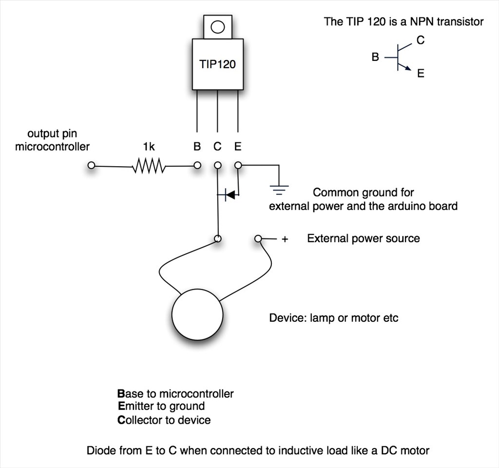
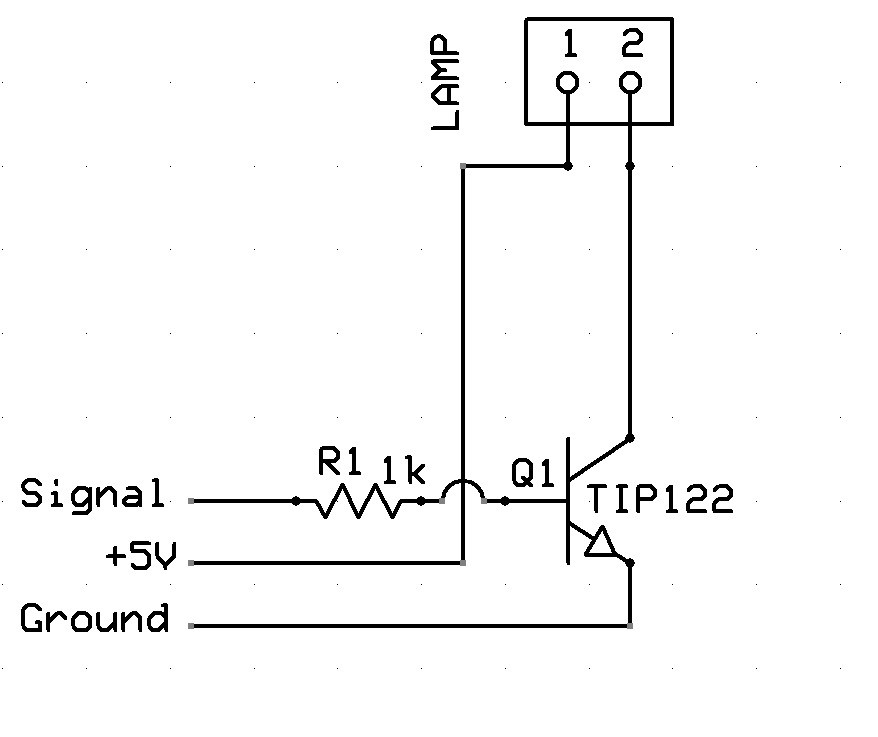
The Schematic:
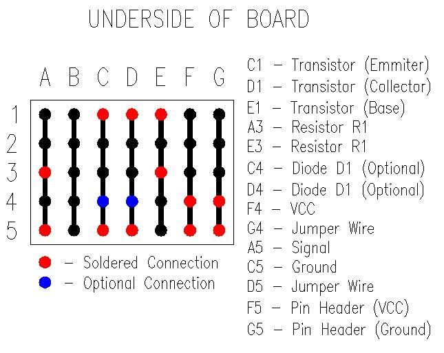
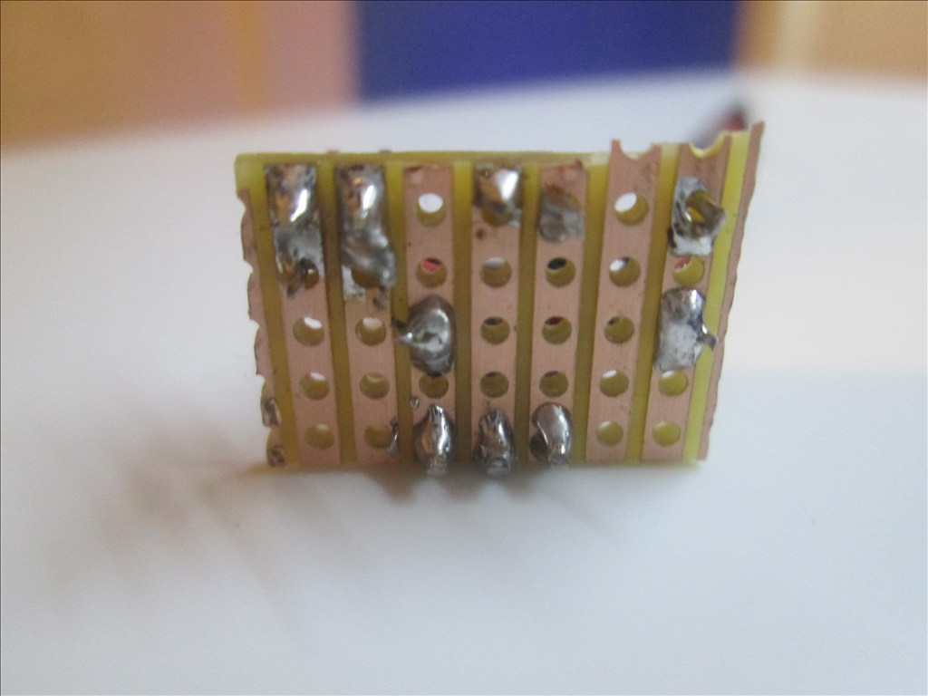
Underside of Board:
Method:
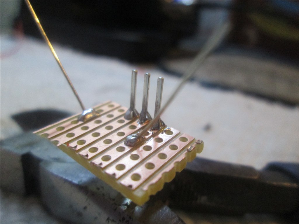
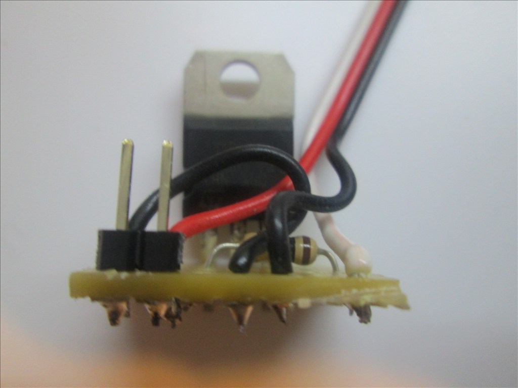
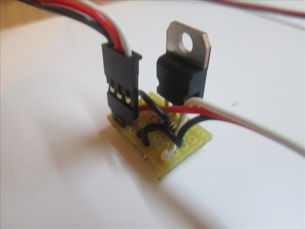
Solder the TIP transistor to the strip board so each pin is on a separate strip of copper

Solder the resistor from the Base of the transistor to a spare copper strip
Cut off the end of a servo Extension and strip back the wires
Solder the Black wire of the servo Extension to the strip connected to the Emitter of the transistor
Solder the White wire of the servo Extension to the strip connected to the end of the resistor (not the transistor end)
Solder the Red wire to a spare copper strip
Use a small off cut from the servo Extension and solder one end to the strip of the Collector of the transistor
Solder the other end of the off cut to a spare copper strip next to the Red wire.
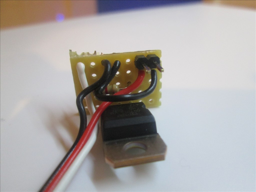
Solder the Pin Header to the copper strips with the red and black wires soldered
Job done. Plug the servo Extension in to a Digital port on the EZB and connect the circuit that needs switching to the Pin Header, I do this with another servo Extension (as I have hundreds of them)
Or a JST connector works very well also
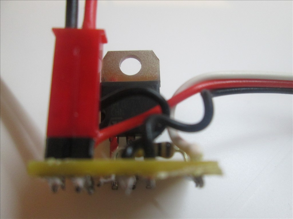
Adding the Diode If using the circuit for a motor or other inductive load a diode needs adding between the transistor Collector and Emitter. This is easily added in to the above circuit.
Bend the leg on the Diode so it will fit though 0.1" hole spacing
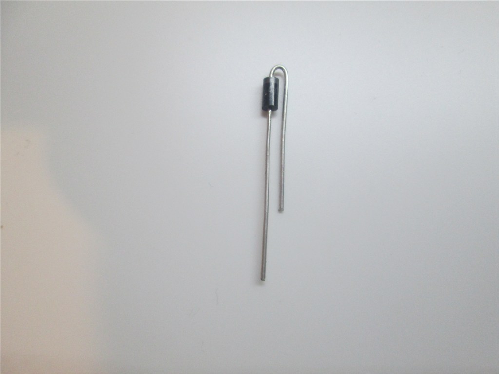
The band on the diode is to connect to the Collector and the other end to the Emitter. It will drop in to two spare holes.
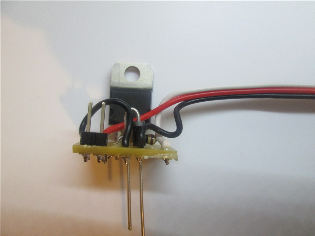
Solder in place and cut off the excess legs.
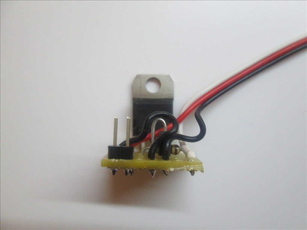
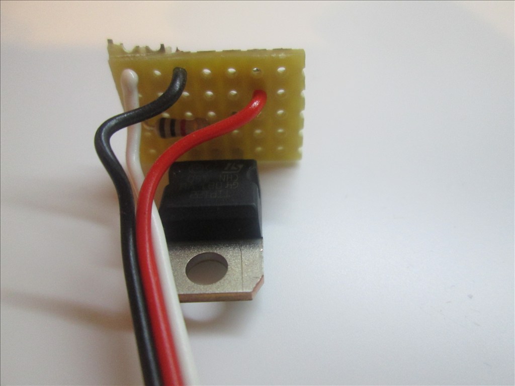
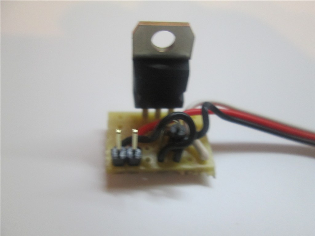
All done. You should have something like this.
Additional notes You may also use a Mosfet for this switching circuit. A IRL3103PBF mosfet can replace the TIP120/122 Darlington transistor. The circuit is the same however the pins on a Mosfet are named Gate, Drain and Source. The mosfet fits in the same place as the Darlington with the Gate to the left (replacing the Base of the Darlington).
Updates:
Edit 1 (2013.03.07): Underside of board diagram added.
Edit 2 (2013.03.07): For some circuits a diode is needed as shown in the first schematic. The board here does have space for a diode (C4 to D4 - would have to be with legs bent to accommodate 0.1" spacing) however I have not shown one - watch this space
Edit 3 (2013.03.07): Underside of board optional connections for D1 added.
Edit 4 (2013.03.07): Added diode information.
Edit 5 (2013.03.18): Added IRL3103 Mosfet information.

When a DC magnetic field collapses in a motor it will send the voltage spike back into the control circuit. When that happens you can burn out your transistor. The diode blocks that from happening by only letting the power through one way. That's why they call it a blocking diode.
Suggested in this schematic
It is not as the usual schematic (or my schematic).
The red jumper links from the second column from the left to the 6th column from the left. These are two empty strips and it basically just allows for a 3 pin header on the bottom right corner to be fitted rather than soldering the servo cable direct to the board.
All components and wires have a slight greenish hue where they connect to the board. All copper strips on the underside run from top to bottom.
It seems it's just complicating matters, I see nothing wrong with the original way, it is the most common way that comes up on google too. And the schematic robotmaker added includes a resistor that I've not used either...
If unsure stick to page 1 post 1 it's the known method...
cathode is always v+ ,cathode isalways the line mark on the diode other side is anode
only RB is needed and same value 1k resistor ,schematic is not mine its off the internet BUT would be same as mine only R is not really needed its used for the base is always off and relay is de-energized BUT is good to have so its not floating,sorry my info is very technical for most,that how engineers are
YES RICH you are correct its only for inductive loads,relays,motors and transfomer
Way it works is when the relay is turn on and then off it produces a very large voltage spick (flyback kickback) or inductive kickback and the diode blocks it
DAVE that is what said too.when on a transistor the diode from collector to base it protects the transistor ,BUT spike is still there and it can cause resets or other noises in to your system
there is a few names for the diode in the cicuit on is flywheel diode ,one called kickback diode ,but its really a blocking diode
MAIN reason i add extra protection ,my company i work for make testers that sells to techs and others and needs not to fail
people who build robots mostly dont care if the part fail or ,cpu resets or sensors unstable BUT i make mine so they never fail or has any problems and then you have to trace it down
I build 7 of the switches and model them after method 1 that are in my robot. Either 1 are controlling motors or lights. They all work great. However there's nothing wrong with over protection. If you have the room and money.
diodes are $.10 TO $.20 each and on this circuit it uses the same diode ,just it a better place so money and room doesnt matter
ONE not great about using transisors is that waste alot of power (wattage) compare to using low ohms mosfets and can easy use a small package compare to transistor T-220 CASE I dont know if you know how mosfets are ,but they use darling transistor in thier design and making it a lot better with less heat and cost is about the same too
I totally agree Dave. I have a few from method 1 in my robot and they run perfectly too.
The good thing is, if you decide you may need that protection it's easy to add in if you made it as method 1. There is space on the board where it can be dropped in - as confirmed by the addition of the diode in the extra info on post 1 (despite it being in not the best place). Option 2 (robotmaker's suggestion) can be added with ease too.
Where most people put it is across the coil ,so it uses less room on the board then in option 1
ON mosfet here is a link to about the same as TIP120 but at $1.96 each
irfz44 mosfet
it is a overkill for transistot since the transistor is rated at 3 amps and mosfet is rated at 25 amps ,but using a low amparage type the cost goes much lower
here is a great match for TIP120 at $.88 each
irfu11pbf mosfet and not metal heat tab on it like on TIP120 HAS and smaller size
looking at the data sheet on this mosfet it has the diode already on it ,so you save more room
IRFU110PBF DATA SHEET
i JUST re-look at the sdata sheet o the TIP120 where you have the diode from collector to emitter the transistor already has one
So putting a diode in parallel with another one doesnt do any good
Thats why reading a datasheet sheet is so important .
TIP120 DATASHEET
NOW on the other hand if you look at the circuit of the darlington you do need a diode across the coil or it with damage the first transistor
THE PATH of the spike voltage goes from collector to the first transistor to R1 to base
Thats the main reason why the diode is needed across the coil,