
I just decided to redo one of my TIP122 Transistor Switching Circuits (mainly because I needed a break from working - there is nothing wrong with the 2 that are already in my Hearoid). So now's as good a time as any to do a small tutorial
This has become an evolving tutorial with additional information and options available being added. The change log at the end of this post explains changes made. Any additional information will be added as and when discovered.
Parts needed: 1 x TIP120 or TIP122 Darlington Transistor or IRL3103PBF Mosfet (see notes at the end) 1 x 1k ohm Resistor 1 x Small Piece of Strip Board (7x5 holes) 1 x Pin Header (1x2) 1 x servo Extension Solder Soldering Iron Cutters
Extra parts needed (if inductive load): 1 x 1n400x Diode as required
Search for part numbers in google or ebay or use your preferred supplier.
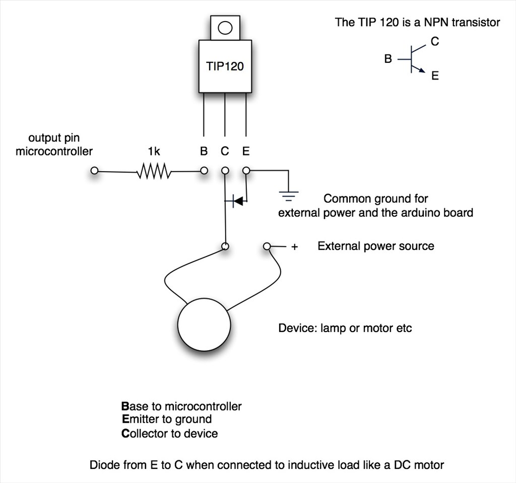
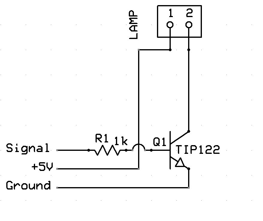
The Schematic:
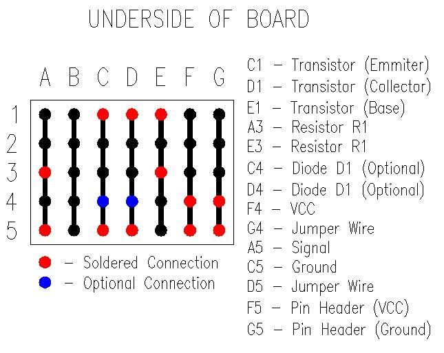
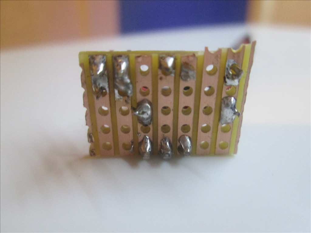
Underside of Board:
Method:
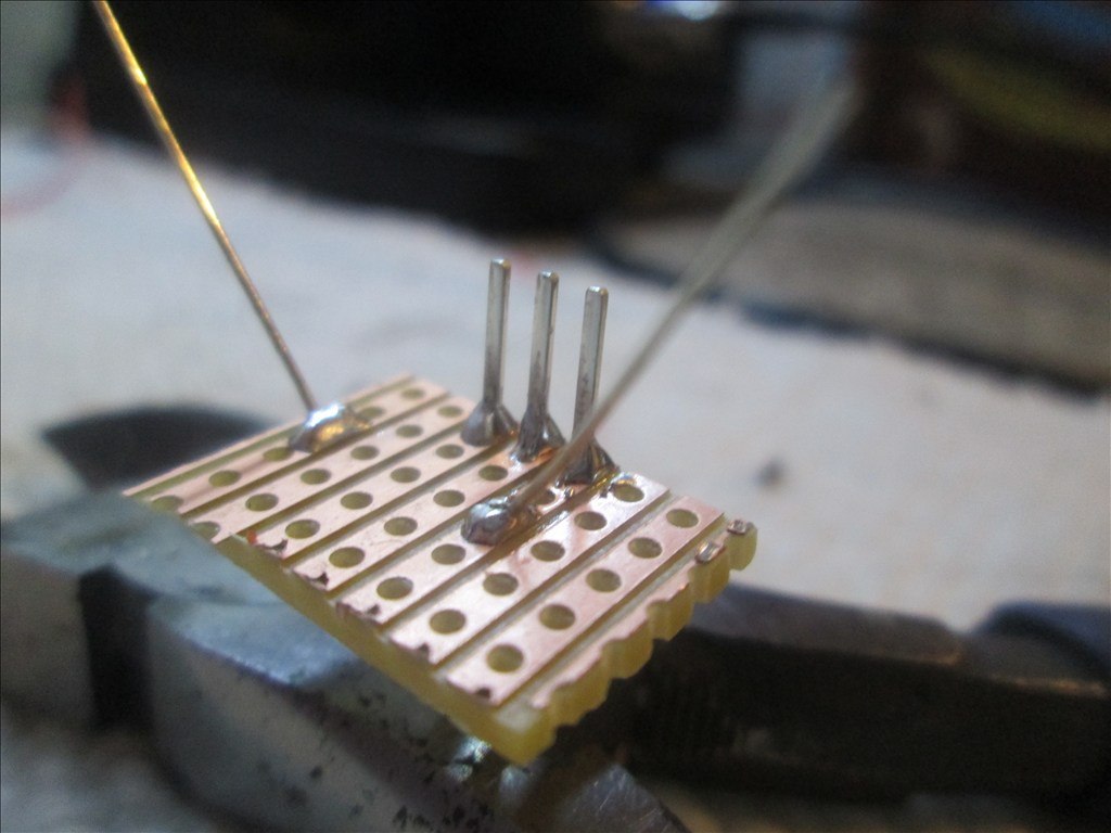
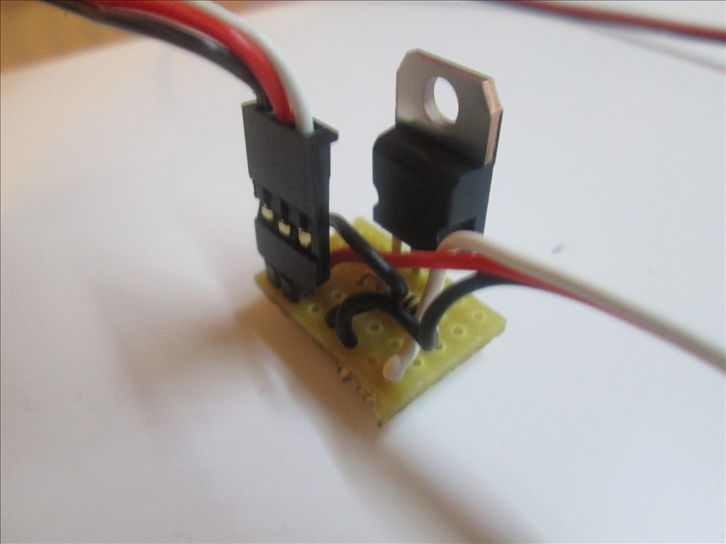
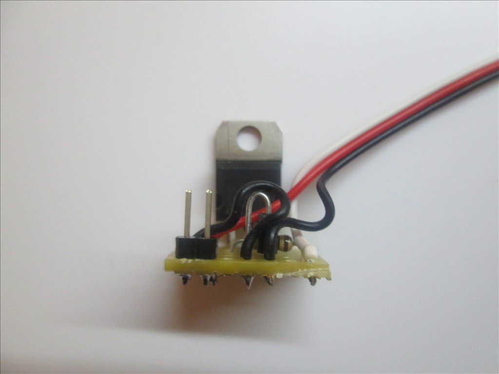
Solder the TIP transistor to the strip board so each pin is on a separate strip of copper

Solder the resistor from the Base of the transistor to a spare copper strip
Cut off the end of a servo Extension and strip back the wires
Solder the Black wire of the servo Extension to the strip connected to the Emitter of the transistor
Solder the White wire of the servo Extension to the strip connected to the end of the resistor (not the transistor end)
Solder the Red wire to a spare copper strip
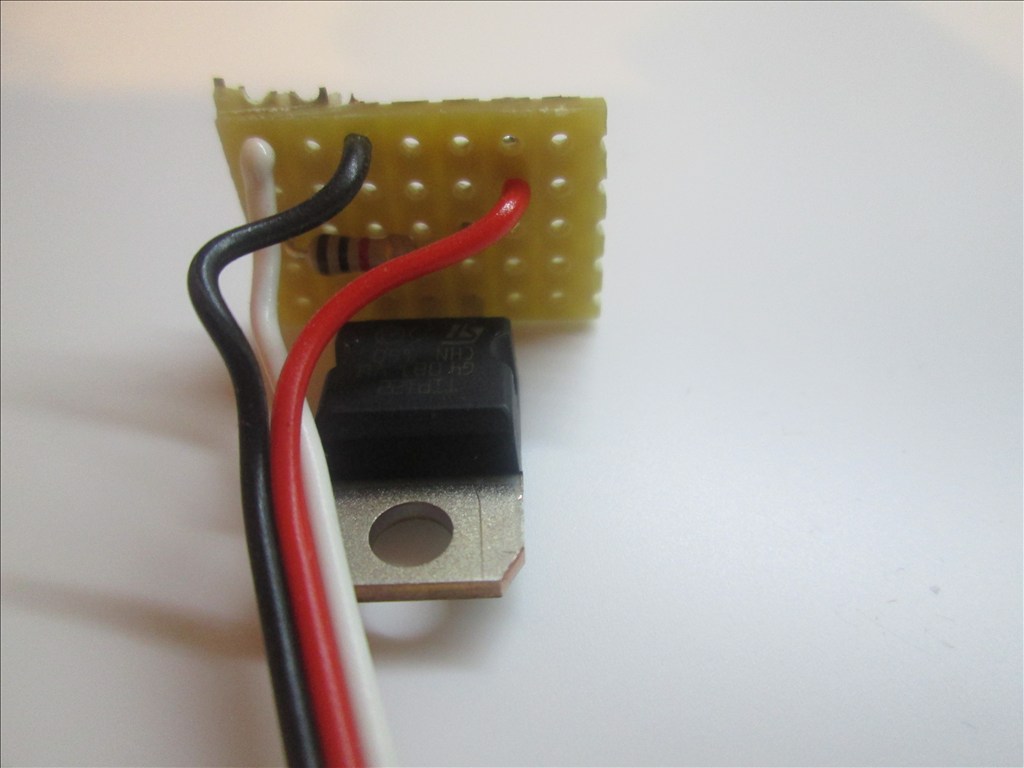
Use a small off cut from the servo Extension and solder one end to the strip of the Collector of the transistor
Solder the other end of the off cut to a spare copper strip next to the Red wire.
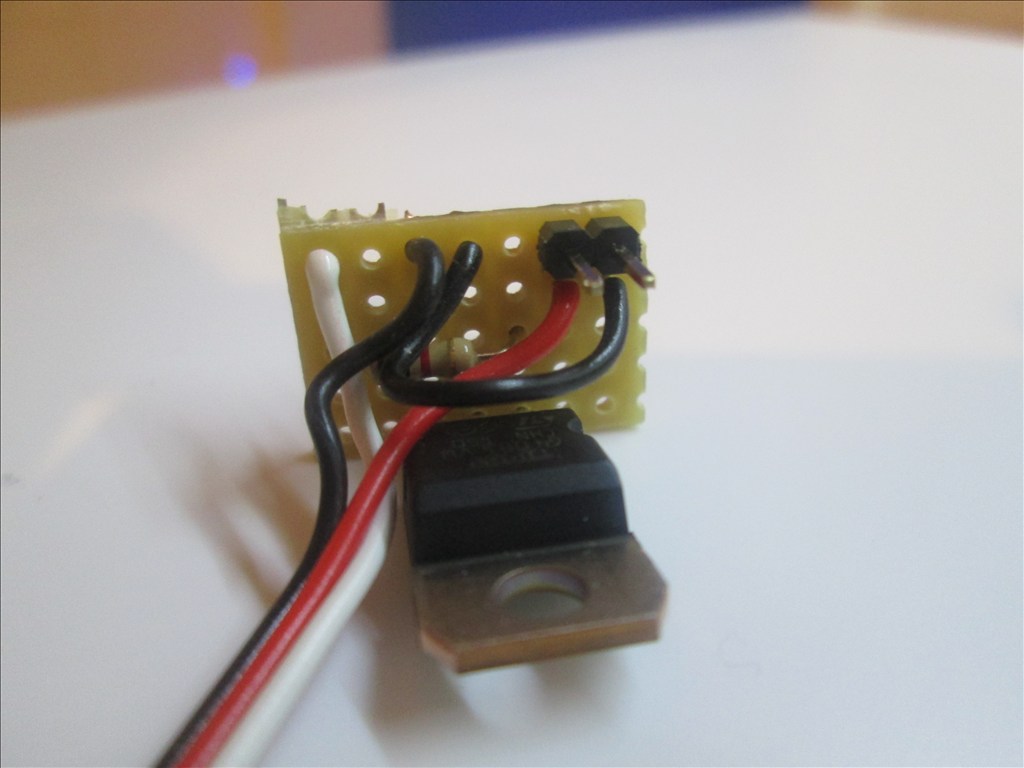
Solder the Pin Header to the copper strips with the red and black wires soldered
Job done. Plug the servo Extension in to a Digital port on the EZB and connect the circuit that needs switching to the Pin Header, I do this with another servo Extension (as I have hundreds of them)
Or a JST connector works very well also
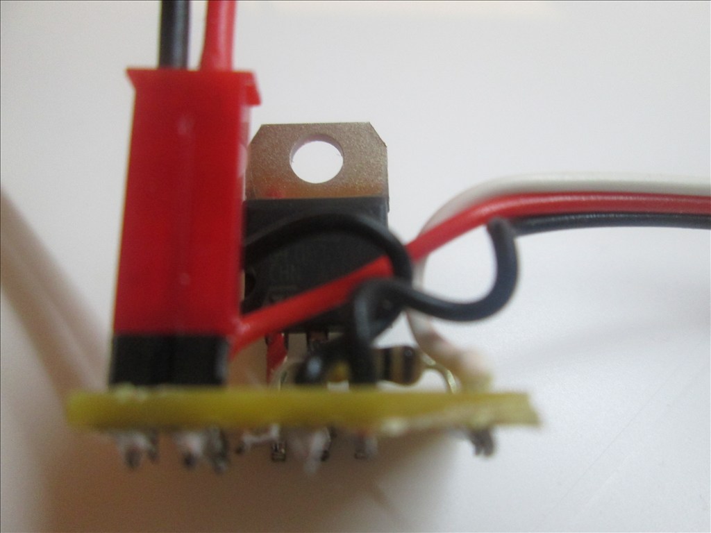
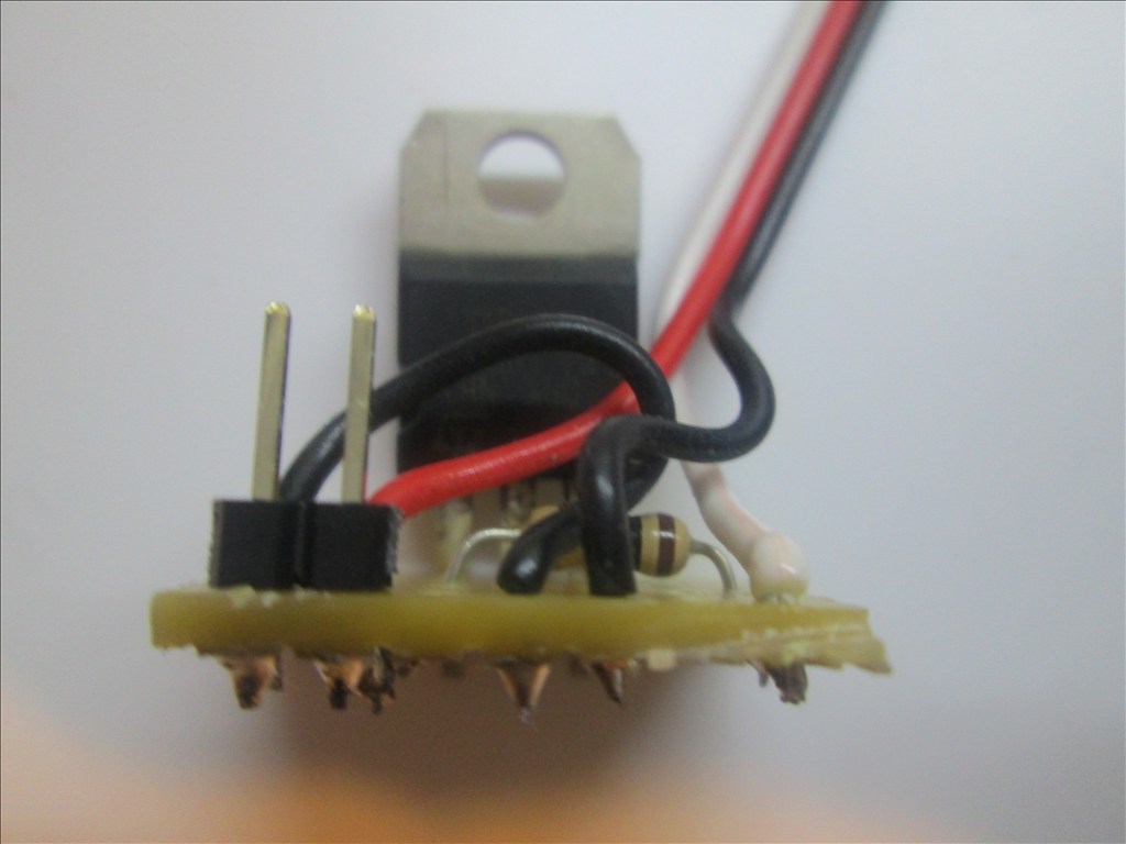
Adding the Diode If using the circuit for a motor or other inductive load a diode needs adding between the transistor Collector and Emitter. This is easily added in to the above circuit.
Bend the leg on the Diode so it will fit though 0.1" hole spacing
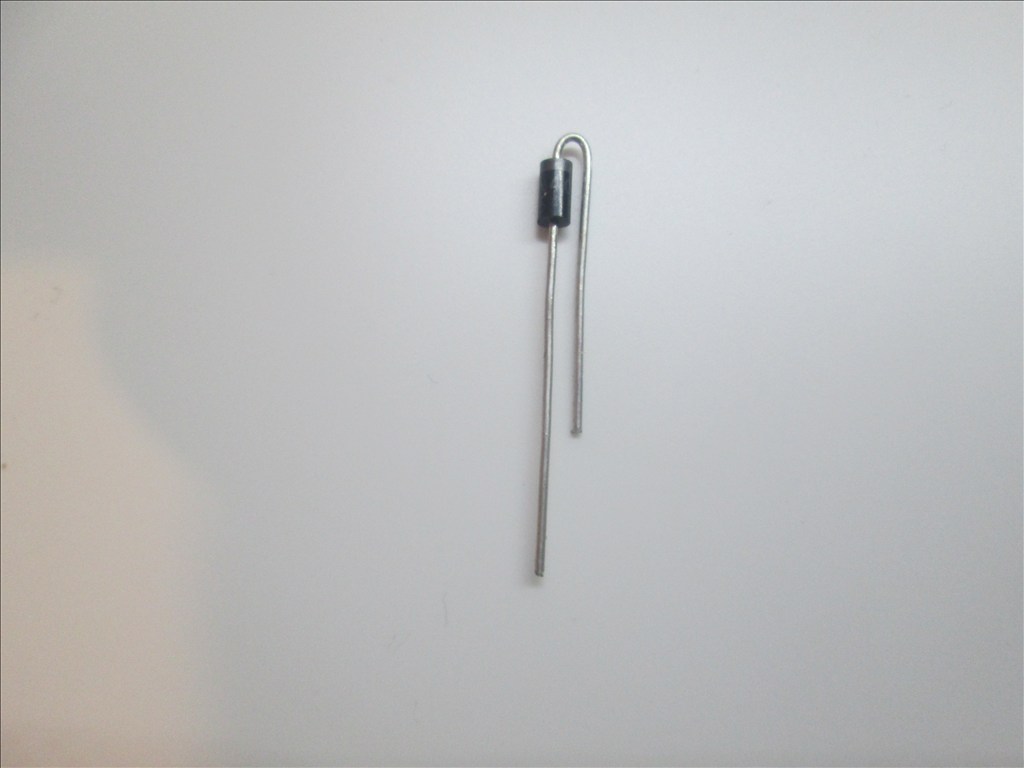
The band on the diode is to connect to the Collector and the other end to the Emitter. It will drop in to two spare holes.
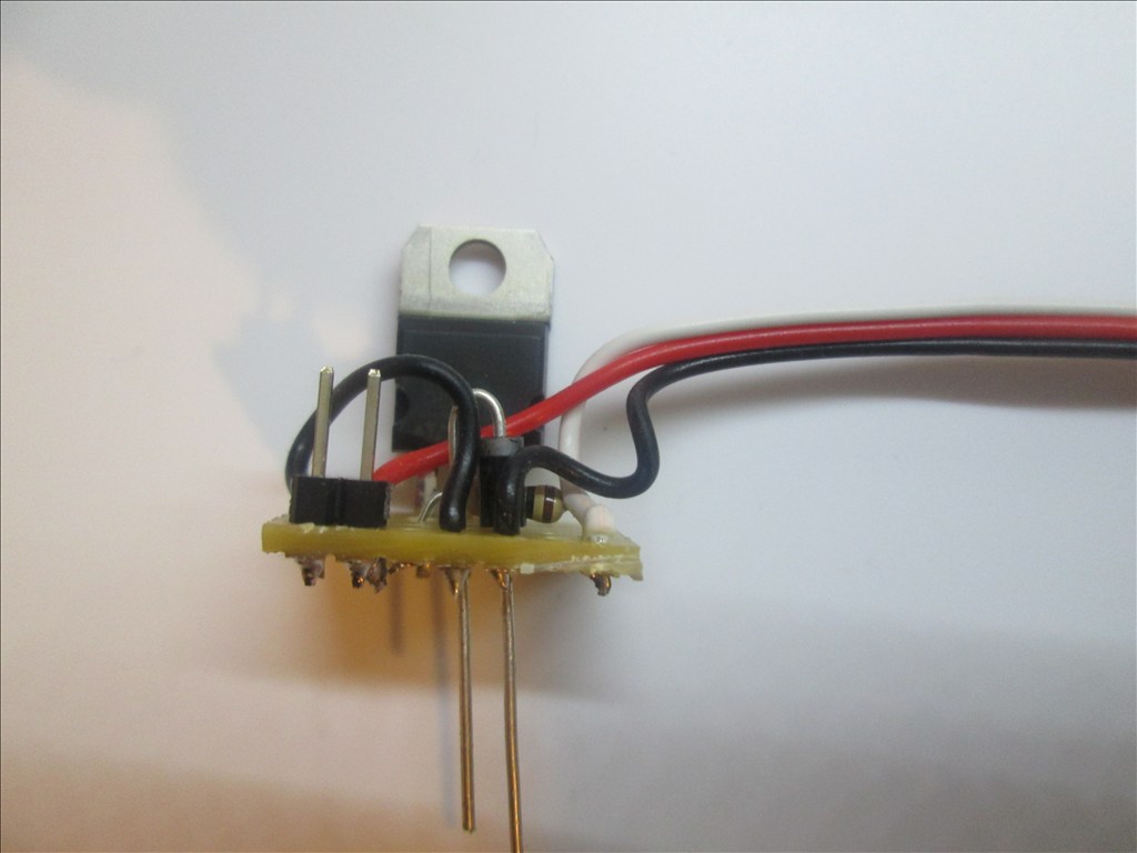
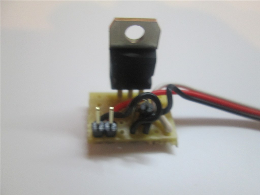
Solder in place and cut off the excess legs.
All done. You should have something like this.
Additional notes You may also use a Mosfet for this switching circuit. A IRL3103PBF mosfet can replace the TIP120/122 Darlington transistor. The circuit is the same however the pins on a Mosfet are named Gate, Drain and Source. The mosfet fits in the same place as the Darlington with the Gate to the left (replacing the Base of the Darlington).
Updates:
Edit 1 (2013.03.07): Underside of board diagram added.
Edit 2 (2013.03.07): For some circuits a diode is needed as shown in the first schematic. The board here does have space for a diode (C4 to D4 - would have to be with legs bent to accommodate 0.1" spacing) however I have not shown one - watch this space
Edit 3 (2013.03.07): Underside of board optional connections for D1 added.
Edit 4 (2013.03.07): Added diode information.
Edit 5 (2013.03.18): Added IRL3103 Mosfet information.

Useless post, please ignore.
Using a coil produces a spike .main term its called is flyback kickback thats where you get the high voltage spike ,its about 100 volts ,but depends on the inductance of the coil.
Here is a link to what is inductive kickback and protection for it ,do some reading it might help
inductive kickback
Useless post, please ignore.
NO ,you will still get 1000 volts in the first transistor to base ,look how current flows Also look at the link it tells the correct place to place the diode.
MOST people dont know this.
Re-edit to fix the grammar a little.
TRYING to fix my grammar with more time now so my info is more readable,but nobody is perfect.
Useless post, please ignore.
Thursday, 21 March 2013
Good Morning Rich !
GREAT Tutorial and P R E S E N T A T I O N !
Your Photo Flow and Detail are most professional documentation. This is the level required for High School Physics and Robotics.
I would enjoy a Tutorial on How You Made This Tutorial and Exactly What Presentation Software you use to do it ?
Thanks Rich,
[email protected]
I use a few different software packages.
The schematic was drawn using ExpressPCB however some of my schematics I draw using AutoCAD and CircuitLab
The renders of the stripboard were made using a combination of Fritzing and Adobe Creative Suite 6