Tip120 & Tip122 Transistor Switching Circuit
I just decided to redo one of my TIP122 Transistor Switching Circuits (mainly because I needed a break from working - there is nothing wrong with the 2 that are already in my Hearoid). So now's as good a time as any to do a small tutorial
This has become an evolving tutorial with additional information and options available being added. The change log at the end of this post explains changes made. Any additional information will be added as and when discovered.
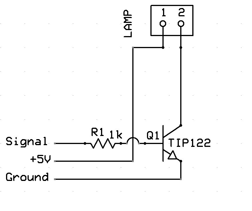
Parts needed: 1 x TIP120 or TIP122 Darlington Transistor or IRL3103PBF Mosfet (see notes at the end) 1 x 1k ohm Resistor 1 x Small Piece of Strip Board (7x5 holes) 1 x Pin Header (1x2) 1 x servo Extension Solder Soldering Iron Cutters
Extra parts needed (if inductive load): 1 x 1n400x Diode as required
Search for part numbers in google or ebay or use your preferred supplier.
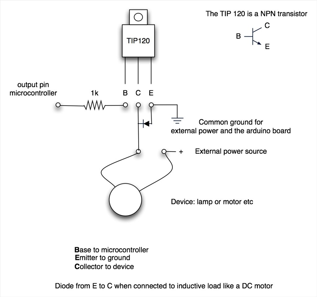
The Schematic:
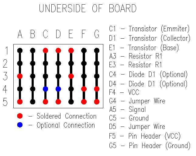
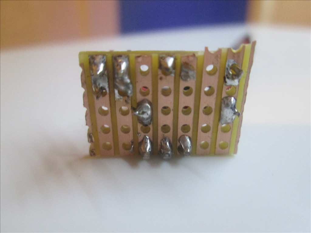
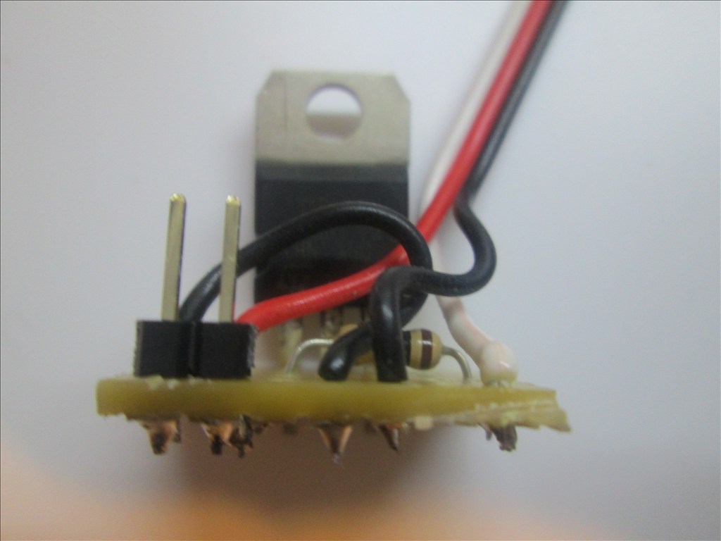
Underside of Board:
Method:
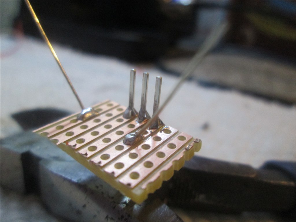
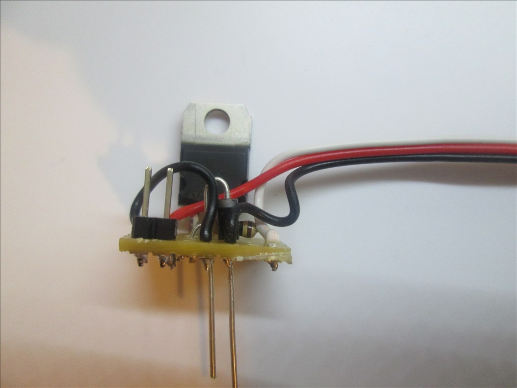
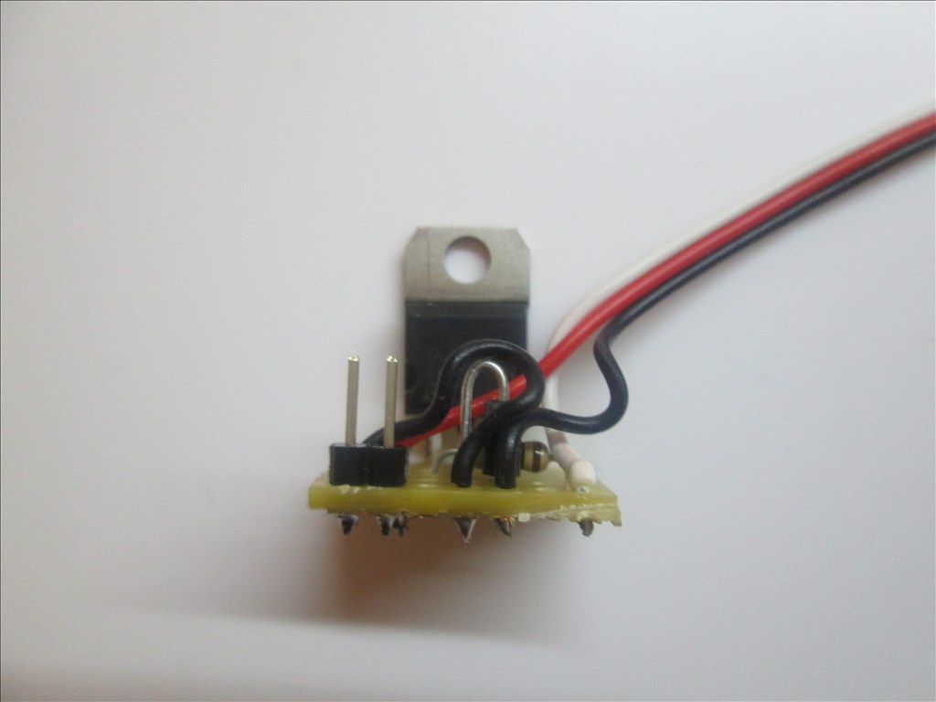
Solder the TIP transistor to the strip board so each pin is on a separate strip of copper

Solder the resistor from the Base of the transistor to a spare copper strip
Cut off the end of a servo Extension and strip back the wires
Solder the Black wire of the servo Extension to the strip connected to the Emitter of the transistor
Solder the White wire of the servo Extension to the strip connected to the end of the resistor (not the transistor end)
Solder the Red wire to a spare copper strip
Use a small off cut from the servo Extension and solder one end to the strip of the Collector of the transistor
Solder the other end of the off cut to a spare copper strip next to the Red wire.
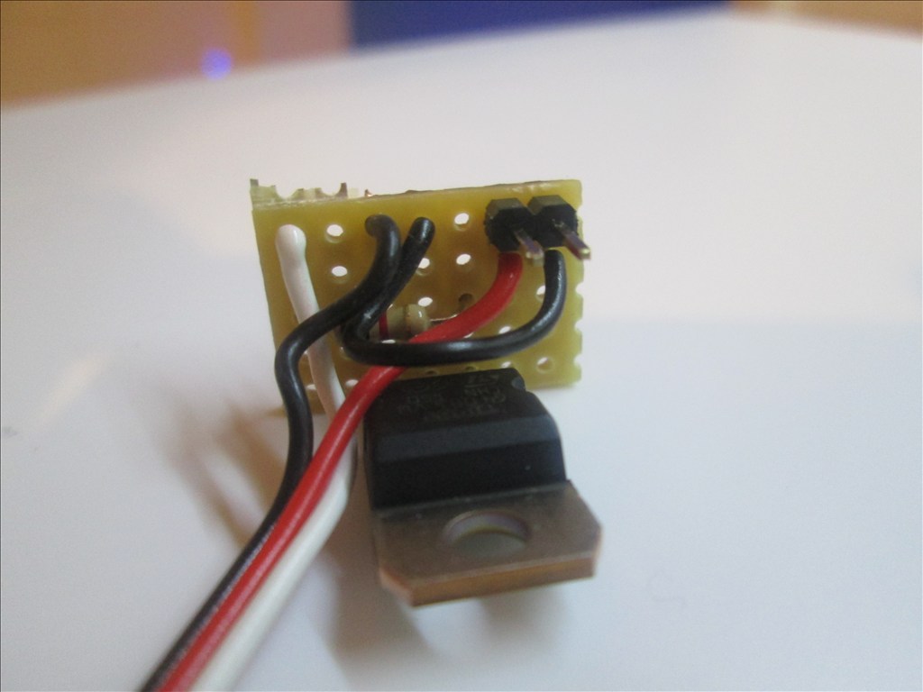
Solder the Pin Header to the copper strips with the red and black wires soldered
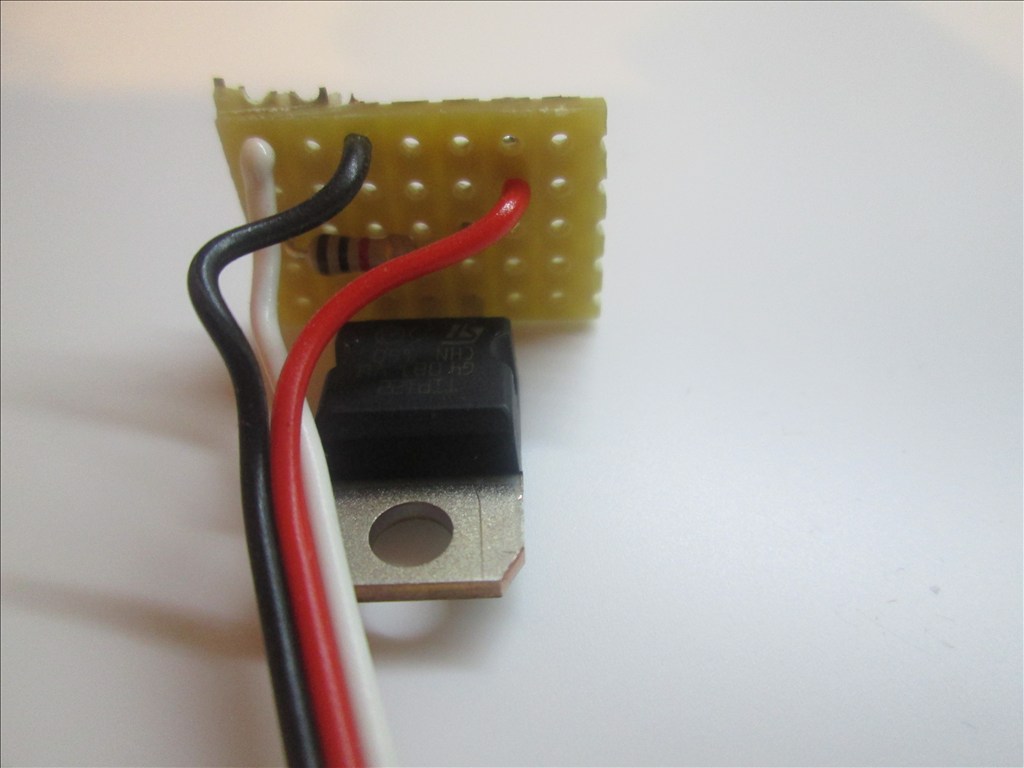
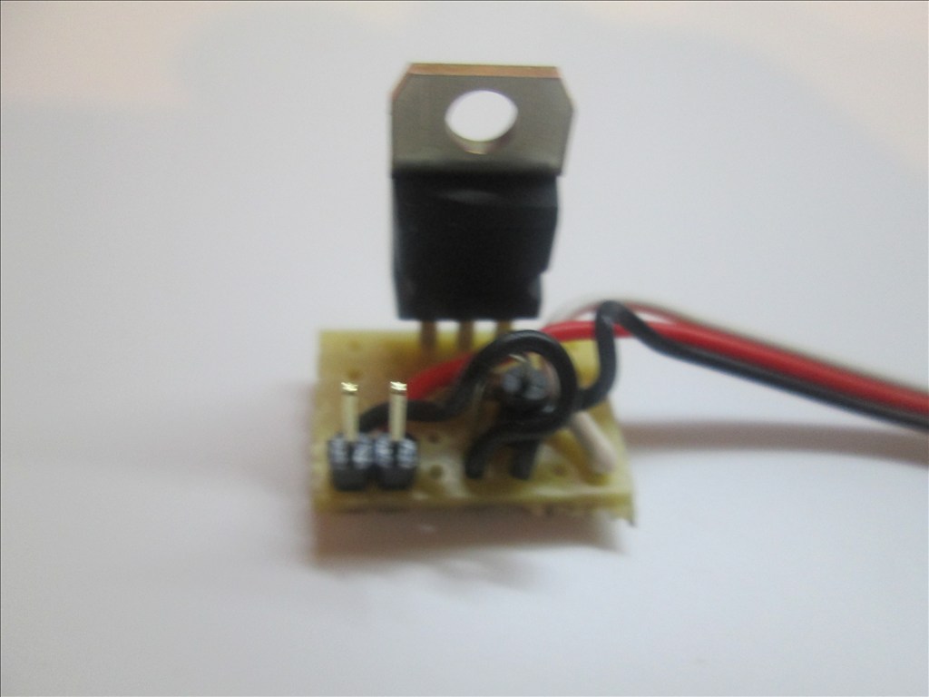
Job done. Plug the servo Extension in to a Digital port on the EZB and connect the circuit that needs switching to the Pin Header, I do this with another servo Extension (as I have hundreds of them)
Or a JST connector works very well also
Adding the Diode If using the circuit for a motor or other inductive load a diode needs adding between the transistor Collector and Emitter. This is easily added in to the above circuit.
Bend the leg on the Diode so it will fit though 0.1" hole spacing
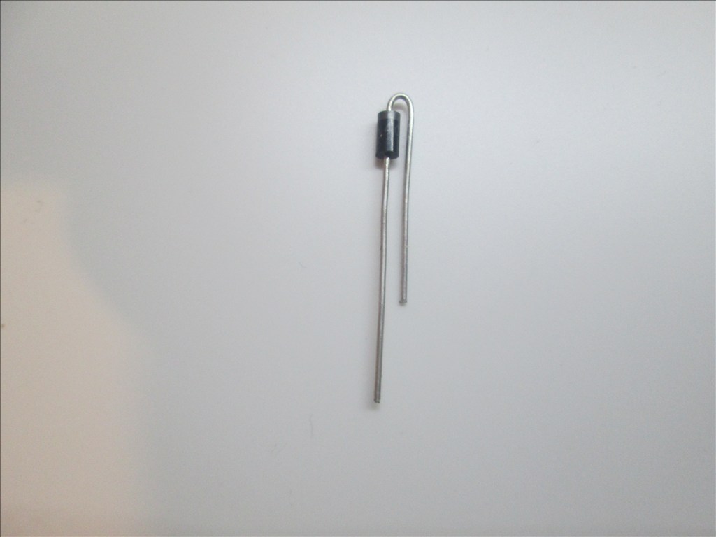
The band on the diode is to connect to the Collector and the other end to the Emitter. It will drop in to two spare holes.
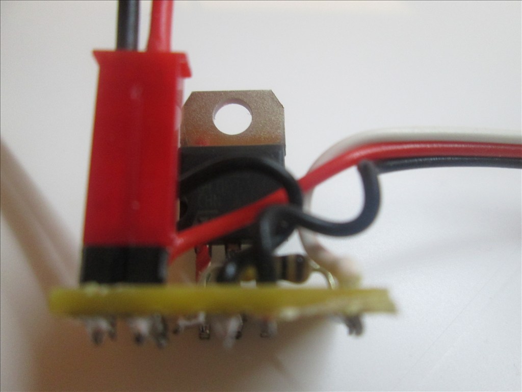
Solder in place and cut off the excess legs.
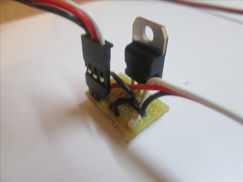
All done. You should have something like this.
Additional notes You may also use a Mosfet for this switching circuit. A IRL3103PBF mosfet can replace the TIP120/122 Darlington transistor. The circuit is the same however the pins on a Mosfet are named Gate, Drain and Source. The mosfet fits in the same place as the Darlington with the Gate to the left (replacing the Base of the Darlington).
Updates:
Edit 1 (2013.03.07): Underside of board diagram added.
Edit 2 (2013.03.07): For some circuits a diode is needed as shown in the first schematic. The board here does have space for a diode (C4 to D4 - would have to be with legs bent to accommodate 0.1" spacing) however I have not shown one - watch this space
Edit 3 (2013.03.07): Underside of board optional connections for D1 added.
Edit 4 (2013.03.07): Added diode information.
Edit 5 (2013.03.18): Added IRL3103 Mosfet information.

@Rich,
A question and a suggestion.
Question: (which I assume the answer is yes), this is Unidirectional, right? I am looking for a way to control the motors in a robotic hand (and later an arm with more motors) and need to be able to reverse the power direction, but I think an H-bridge is overkill, and the one I own is serial rather than servo emulation, so before buying another I thought of this tutorial, but it seems it won't fit my need unless I am mis-reading.
Suggestion: You may want to go through this thread and do the same thing that Troy did an edit the no longer relevant posts so new users don't think you are insane arguing with vapor.
Alan
Think of this as a basic on off switch, nothing more, nothing less. It makes the circuit and therefore it illuminates the lamp, spins the motor forwards, sounds the buzzer or whatever. It can't be used to reverse the direction of a motor (that I am aware of).
However, you could use a servo board. I don't know much about it, I tried once but realised halfway through I could fit a servo in there so did it that way. But what i was trying was to strip down an old servo that's gears are shot, or just a cheap one and remove the motor from the board. Connect up the new motor. Connect up the pot (if you want feedback) or convert it to a modified servo. I have no clue on how to do it but google will know Just an idea to avoid using a HBridge.
I plan to edit all topics etc. I've done a few, but I'm sure you are aware there are rather a lot where bad things happened. Eventually I will get there I think the first post is updated now... unless I'm thinking of a different one. But yes, you are right and it is on the list
Thanks for the idea about cracking open a servo. Hadn't even though of that. Should work for the hand, which has small motors.
Alan
I'm told they (standard servos) can handle about an amp. I've done it with motors in Pinhead's....errr head. Since the motors were small and most likely not draw an amp I used micro servo boards.
Pinhead
Standard servos Like futuba, power HD, tower pro can handle continuous 800ma ( .8 amps) High torque servos like power HD 1501mg , tower pro 995, hitec 645mg handle approx 3 amp continuous 5 amp max
If you want to make sure you have enough juice and the benefit of digital then use a high torque servo control board.
Oh I think I just had an " idea" using a servo control board from a high torque servo could be a easy to use alternative to an hbridge in general. Plus they are like 20 percent the size of a l298n board. Hmmm
I've often wondered if a servo board could drive a motor for driving a robot, or 2 of them to be more precise. A 2 wire h-bridge sure would help me out on Melvin's lack of Digital ports. Until you mentioned the high torques I had just dismissed the idea but knowing they can handle 3A it brings it back on to the drawing board.
@jstarne1 and @Rich ...are you thinking something like this.. PWM servo controler for 14.95$...it however does not list the current limits..