
Tip120 & Tip122 Transistor Switching Circuit
I just decided to redo one of my TIP122 Transistor Switching Circuits (mainly because I needed a break from working - there is nothing wrong with the 2 that are already in my Hearoid). So now's as good a time as any to do a small tutorial
This has become an evolving tutorial with additional information and options available being added. The change log at the end of this post explains changes made. Any additional information will be added as and when discovered.
Parts needed: 1 x TIP120 or TIP122 Darlington Transistor or IRL3103PBF Mosfet (see notes at the end) 1 x 1k ohm Resistor 1 x Small Piece of Strip Board (7x5 holes) 1 x Pin Header (1x2) 1 x servo Extension Solder Soldering Iron Cutters
Extra parts needed (if inductive load): 1 x 1n400x Diode as required
Search for part numbers in google or ebay or use your preferred supplier.
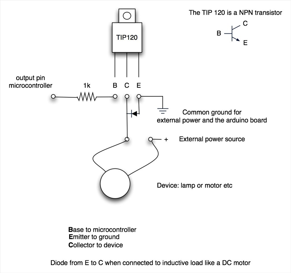
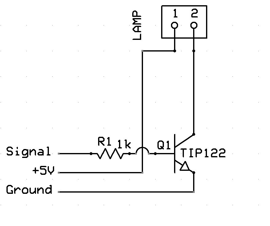
The Schematic:
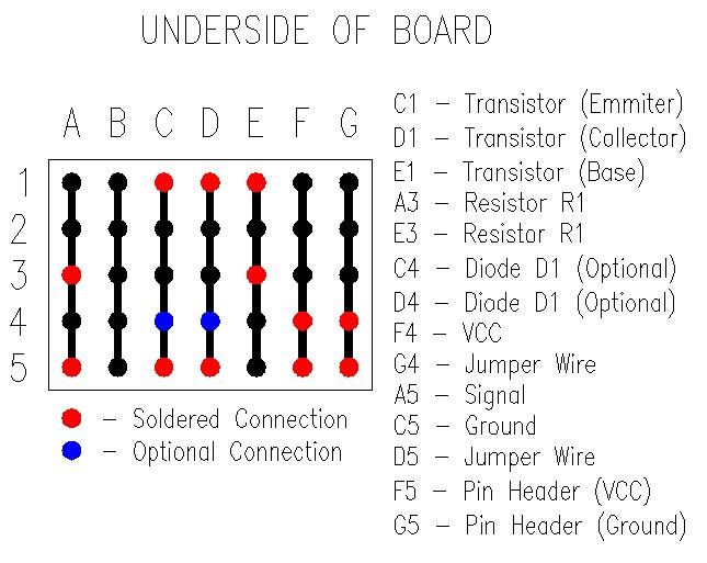
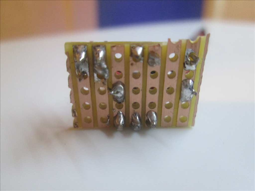
Underside of Board:
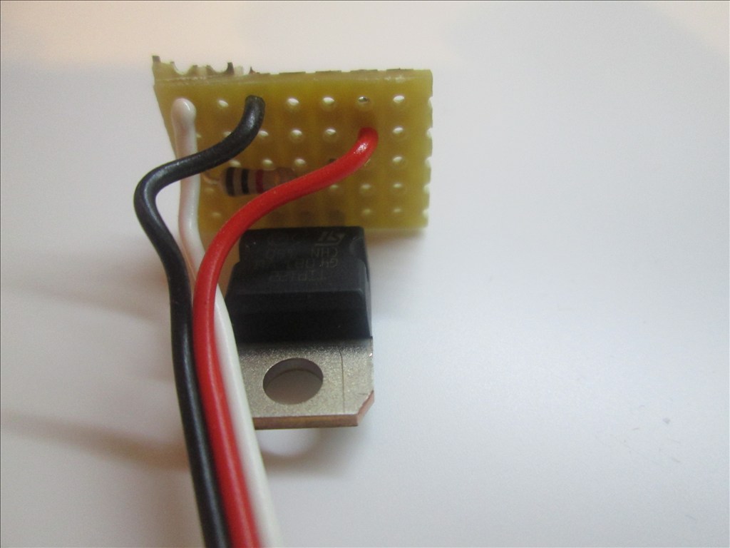
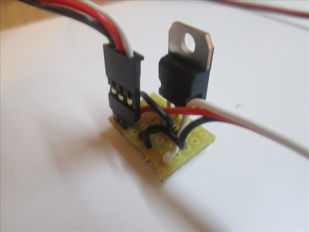
Method:
Solder the TIP transistor to the strip board so each pin is on a separate strip of copper

Solder the resistor from the Base of the transistor to a spare copper strip
Cut off the end of a servo Extension and strip back the wires
Solder the Black wire of the servo Extension to the strip connected to the Emitter of the transistor
Solder the White wire of the servo Extension to the strip connected to the end of the resistor (not the transistor end)
Solder the Red wire to a spare copper strip
Use a small off cut from the servo Extension and solder one end to the strip of the Collector of the transistor
Solder the other end of the off cut to a spare copper strip next to the Red wire.
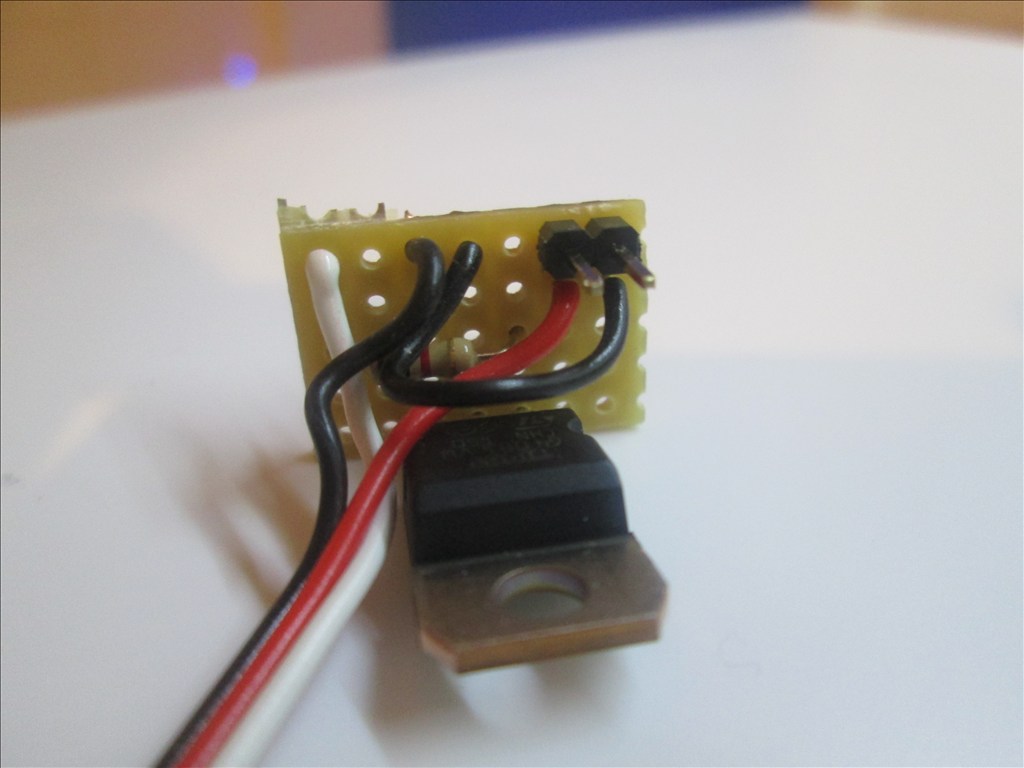
Solder the Pin Header to the copper strips with the red and black wires soldered
Job done. Plug the servo Extension in to a Digital port on the EZB and connect the circuit that needs switching to the Pin Header, I do this with another servo Extension (as I have hundreds of them)
Or a JST connector works very well also
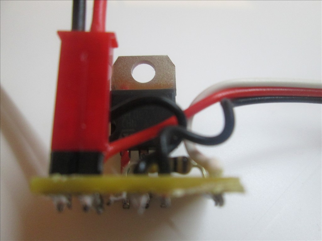
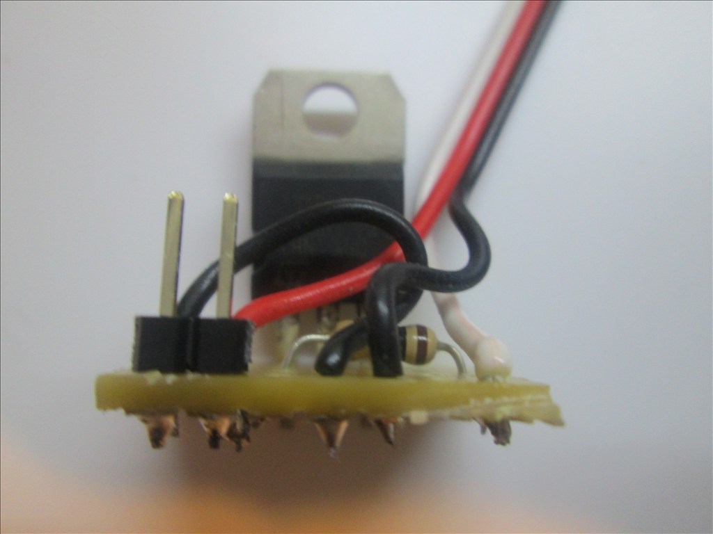
Adding the Diode If using the circuit for a motor or other inductive load a diode needs adding between the transistor Collector and Emitter. This is easily added in to the above circuit.
Bend the leg on the Diode so it will fit though 0.1" hole spacing
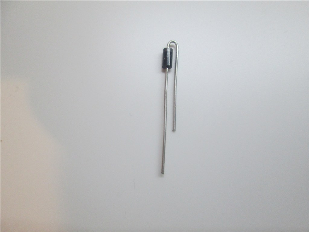
The band on the diode is to connect to the Collector and the other end to the Emitter. It will drop in to two spare holes.
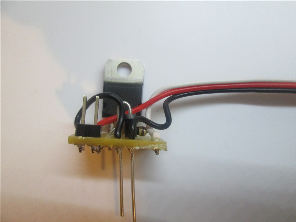
Solder in place and cut off the excess legs.
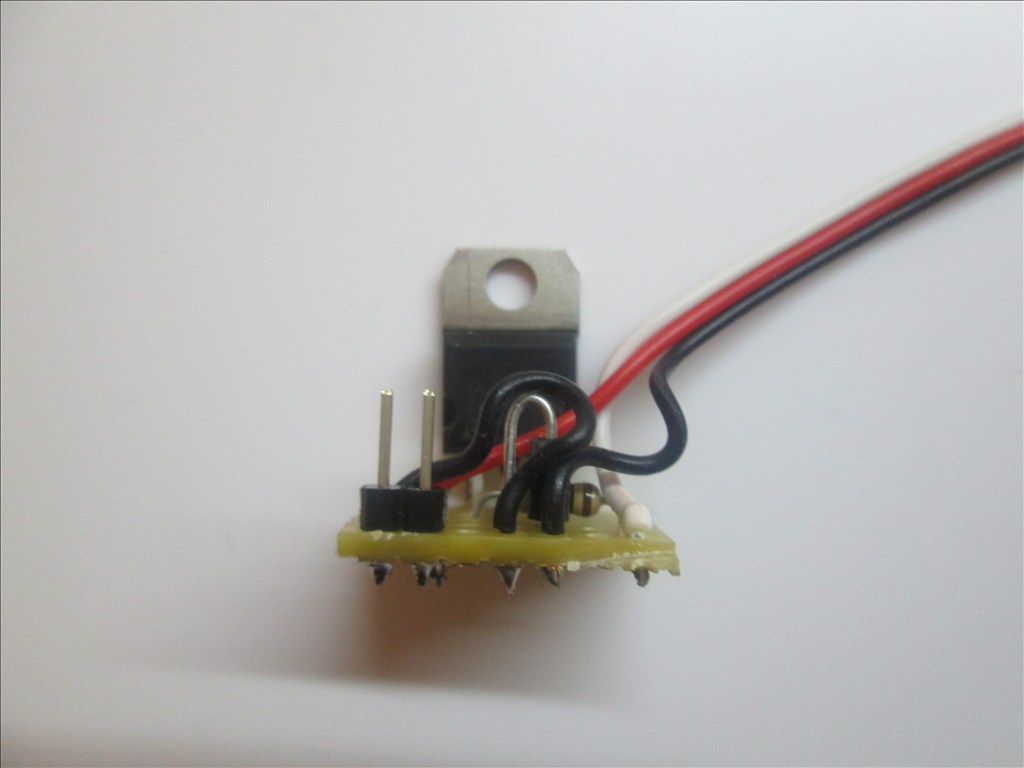
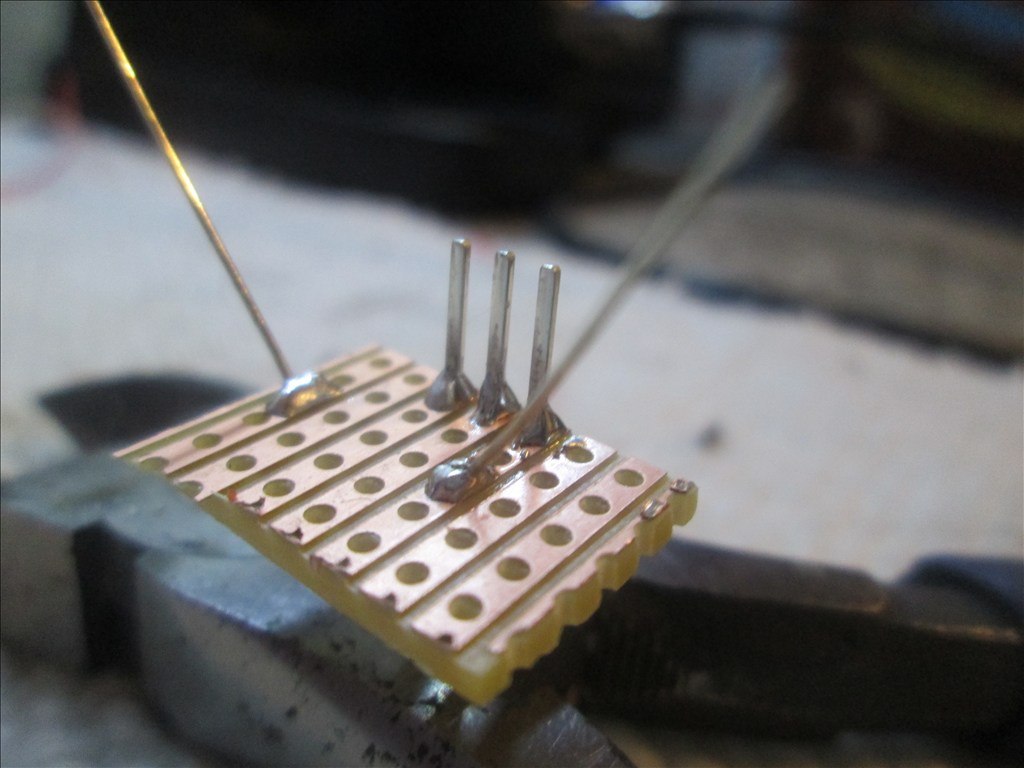
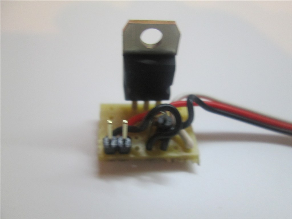
All done. You should have something like this.
Additional notes You may also use a Mosfet for this switching circuit. A IRL3103PBF mosfet can replace the TIP120/122 Darlington transistor. The circuit is the same however the pins on a Mosfet are named Gate, Drain and Source. The mosfet fits in the same place as the Darlington with the Gate to the left (replacing the Base of the Darlington).
Updates:
Edit 1 (2013.03.07): Underside of board diagram added.
Edit 2 (2013.03.07): For some circuits a diode is needed as shown in the first schematic. The board here does have space for a diode (C4 to D4 - would have to be with legs bent to accommodate 0.1" spacing) however I have not shown one - watch this space
Edit 3 (2013.03.07): Underside of board optional connections for D1 added.
Edit 4 (2013.03.07): Added diode information.
Edit 5 (2013.03.18): Added IRL3103 Mosfet information.

IT does no good to email you,oi tried to be a nice man and sent you a very long apology to you RICH and see what you sent back to me.
IT takes a good MAN to apologize and a better MAN TO ACCEPT the apology ,but with your comment you sent me your not both of theses
IF you send me a nice email .like i sent you i would remove this.
I was given a idea ,do not reply to you RICH and for you not to reply to me. AND there will be no more problems ,end of story
I WILL NOT REPLY BACK
Well guys setting all the drama aside, look on the bright side. You are both obviously intelligent and talented in your own rights respectively. Rich to answer your previously posted question about diode placement (and this is not me choosing sides by any means merely attempting to offer non biased rational clarification) robotmaker's placement of diode is not the only "correct" placement it merely offers added protection to the circuit. Rich your original placement simply didn't protect the first transistor in the darlington and the TIP has built in protection with diode to second transistor which is the same as the one you were adding. That's all not a big deal. Also in the spirit of full disclosure Rich was also right about the diode unnecessary unless inductive load. Furthermore, depending on the motor Rich's original design probably does work just fine for most applications. However, Robotmaker's design is the more reliable one. As far as mosfet vs. darlington you two are not the first to disagree on this and you probably won't be the last. The advantages of the mosfet are undeniable and Rich's original post gave that as option. That being said I am guessing that the either method is just fine for most applications used by the members of this forum. I can answer most any question concerning problems created by inductive loads as i work as an engineer for an electric utility provider and have to keep an eye on that along with many other conditions on the system. I'm sure you both knnow all of this, I am posting so if any other readers look at this may it helps pulls some fact away from the dispute. I mean no disrespect to either of you and truly hope that this offends no one.
The mosfet design he just added after he saw my post,as you can say he re-edit it
THERE will be no more DRAMA from me on any posts of RICH
AS about the mosfet the LINK proves what i said a long time ago before he added the info on this post.
I am only trying to help others to build a good robot design
GOOD to see someone thinks i am right.
SO LETS TRY TO BE FRIENDS AND BUILD ROBOTS PLEASE
well like i said i didn't read any of this as it was going on you had me curious with your question last night so i was just trying to see what all the fuss was about. hey man i'm trying to be friends with everybody on here. can't we all just get along as far as building robots for me the jury is still out. it's been about ten years since i did any work on anything less than 14.4kV so whenever i get my kit i'll get started and see where it goes i guess. I MAY EVENTUALLY NEED A LITTLE HELP FROM EVERYBODY TO MAKE MY STUFF WORK. i haven't done an electronics diagram like the one on this post since school.
same with me JDAWG,i try very hard to be nice to others mostly thats how i am,never see me get mad or anything.
LETS hope the drama has stop so no more problems ,drama is bad for the forum and its in any club you join also.
I love being friends with everyone.but doesnt alway work out.
Deleted. No longer relevant. Moderator please remove.