Asked — Edited

Testers Needed , Inline Servo Adjustable Regulators

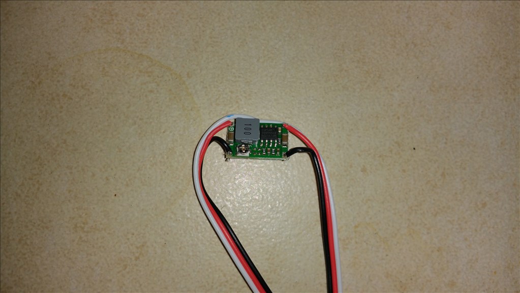
Hello everyone , I sourced switching regulators that are also adjustable from 4.75 volts to 14 volts , I added standard servo ext plugs so they plug directly into your V4 EZB. I will be making these for myself and the community so I hope everyone likes them. Please be aware I can only send these where you will not have rediculous duties or shipping fees as I will just mail them in a standard envelope.

I am looking for 10 testers , try them out , see how you like them and report back. First one is free!

User-inserted image

User-inserted image

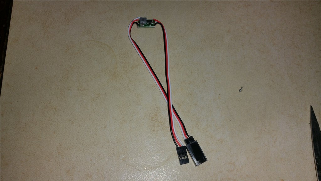
I can also make them with jumper style pigtails for sensors , but I will get in the pigtails later.


ARC Pro

Upgrade to ARC Pro

Experience the transformation – subscribe to Synthiam ARC Pro and watch your robot evolve into a marvel of innovation and intelligence.

#1  

I am considering a red epoxy coating to protect them from electrical contact and shorts with other exposed pins. I initially was thinking of shrink wrap but the Potentiometer must be exposed to adjust the voltage.

#2  

Josh that is actually a really good idea and a great solution. How much current can those regulators supply? Just one minor question.... Those servo extension wires you have in the picture, what gauge are they? I have some of those and I think mine are something like 24 gauge.... I use them for sensors only because they are too thin to use with my inMoov's HS-805bb servos.... I think the hitec servos use 20g twisted pair.... I would try and use at least as heavy gauge wire with them as comes with the servo themselves...

Canada
#3  

Josh, I am interested also. USPS delivery should not be a problem. please send me an EMail @ gilleswhite@videotron.ca and I'll give you my address.

#4  

Hi Josh, I'm interested in them and would like to be tester. weyoun7ster@gmail.com

#5  

Josh,

I could use 3 of them for my current project. I need 12V for a 3LED strip, 7.4V for EZ-B and 5V for an audio amplifier. My source voltage is 13.8 V.

I would be willing to pay for them.

I am in Southern California. stafford.irvin@att.net

United Kingdom
#6  

Clear oversized heat shrink would solve the access problem. Just slide the regulator out of the way. Either that or make a hole where the screwdriver needs to enter to adjust (presuming it's a screw adjust) Increase the extension cable's gauge too (what's the max current they can supply? Work out the cable size based on the worst case scenario and cover yourself). Presumably the signal cable is not split and one continuous piece from one connector to the other?

Just a few thoughts, do with them what you will ;)

PRO
Belgium
#7  

jstarne1

i use this one for coating a print.it dry's very quick.

coating

#8  

Switching regulators are the very best way to go. They are usually small, run cool and power efficient. Very little power loss. However make sure you know how many amps (current ) your going to draw through them and buy one that will handle the load. Small sensors will usually draw well less than an amp. Motors and servos may draw many, many amps.

Josh, has a fantastic idea and offering here. Josh, could you tell us what this is rated for?

#9  

Josh, I will be a tester, and consider more later. I think it is something people need. I live in the Midwest USA. Thank you Steve S sdstud1975@yahoo.com

#11  

Here are manufacturer specs, in short it is rated at 3 amps of current. This is enough to drive a high torque servo according to most manufacturer specs.

Module Properties: non-isolated buck Rectification: synchronous rectification Input voltage: 4.75V-23V Output voltage: 1.0V-17V Output Current: 3A Conversion efficiency: 96% (maximum) Switching Frequency: 340KHz Output ripple: 30mV (no-load) Load regulation: ± 0.5% Voltage regulation: ± 2.5% Working temperature: -40 ? to +85 ? External dimensions: 17 * 11 * 3.8mm

Everyone who didn't post their info , email me kandyred@gmail.com , others I will email you tommorow.

#12  

@Josh.... One good point is the lower the voltage you set the regulator at the more current it should be able to provide....

#14  

Nice, but i think you can also get same kind thru Dimension Engineering.

#15  

@RoboHappy You mean this 3A adjustable regulator At $25 a pop? You can pay that if you want. I'll wait to see what Josh can provide them for, which I am sure is going to be a far bit cheaper...

#16  

Wow , the dimension regulator is pricy and has less range of operation. If you buy that.... it is because your brand loyal. Yes I will be offering them at less than half that price!

#17  

@Dave , I believe you asked about the wire thickness, it is 20 Guage according to my wire sizer. It is the thickest wire that will slide through the eyelets once the tips are tinned with solder. 20 Guage is more than enough to carry 3 amps of current that the breakout board it rated for. :)

I soldered up a few sets and I will be mailing the testers out tommorow. Please take note the output voltage is adjusted by the adjustment screw which is on top of the potentiometer. After testing your welcome to solder on whatever connectors or wire you like , just report back on the experience of the switching regulator / DC to DC converter. Thank you for everyone's participation!

#18  

User-inserted image

User-inserted image

These are naked breakouts , the future models will likely be clear shrink wrapped with a hole punched for the potentiometer adjustment screw. Also there will be a holographic security sticker labeling the model , date and serial number for each unit. These are manufactured for me by a chinese pcb company. I intend to keep many on hand for short delivery times.

#19  

@Josh... Do you have a price point yet? Also, would you be willing to sell in lots with just the board itself? I am thinking about buying 20 from you if you are able... And I wouldn't mind doing my own soldering.... Not that I don't trust yours or anything :)

#20  

@Richard , Sure , at this time the price point is set for 7 dollars even each with the servo extension soldered on. 5 dollars without. Free shipping to the USA. however if you buy 20 we can talk privately about a discount. :)

#21  

Thank you for this needed solution. when you are ready to push some out and need testing please contact me as I architect them into our R2D2 Build. This will give us another power option and can possibly simplify the wiring of this complex system.

Woohooo Thanks again.

Please contact me soon as I can place an order. I will keep my eyes open here for updates as well.

#22  

I'll send you and email later @Josh.... Thanks bud...

#23  

@Josh, No I didn't ask about the wire size. Only how many Amps this little gem will handle. You answered already with 3 amps.

Very nice work and sweet product. Very much needed for the EZB community.

#24  

Thank you Josh, I received my adjustable inline voltage regulator today. Using my voltage meter, I realized 8.1 volts directly from my EZB4 pin outs and @ the input side of the regulator. When I connected to the regulator output, it showed 7.5 volts without any adjustment. After turning the adjustment screw, I was able to get close to 5 volts. The adjustment is very sensitive on my unit, and did settle out some. I will later try testing the regulator on one of my high demand shoulder servos. Thanks, Steve S

#25  

Thankyou for your feedback Steve! It does appear it gets within .1 Volt's of 5 volts. It appears that it may be suitable for those needing 5 volts for a ACC power on a sensor. Feedback on this is appreciated of course , I have never used 5.1 volts intentionally on a 5 volt sensor ,but it does sound ok to me . :)

When you put a load on it please pay attention to the temp if the coil and IC. Based on tester feedback I will make the call on the need of a aluminum heatsink. The end product will be heatshrink wrapped in clear and a hologram on the back with serial number.

#26  

"hologram on the back with serial number" - what is this, Star Trek? ;)

I got mine today and I'm looking forward to trying it this weekend. Thank you Josh for the sample and letting me test it. Other than heat, is there anything else you'd like us to test? Do you use to post results here on email you directly?

#27  

HI Justin , Yes just pay attention to heat , when you test it check the amps your servo was drawing and the voltage you operated it at. Also post the voltage and power source as well please. If I see that the unit sometimes gets toasty then the final version V1 will include a heatsink under the heatshrink and label.

Also about the hologram security label.... yeah dude this is star trek! Haha.

I am doing it for a couple reasons. First being tracking who owns what regulator for warranty and quality control purposes. The stickers are security type with dual strength adhesive that will separate when removed voiding any warranty. Each one will be numbered and those who already received testers will be assigned a number and sticker mailed as well. Here are the manufactoring samples received today , when I get the serial preprinted I will have to order 1980 of them at once (strange number) they are .4" square with fillet corners.

PRO
USA
#28  

Dang, I've ordered 3 of these from EZB an it takes awhile to get them. (I need them yesterday of course) so I ordered the same they have in stock at Polulu. Your price point is a really good deal. I'll grab a few for sure when you go into production.

#29  

Here's the hologram security label proofs User-inserted image

Thanks FXrtst , the idea is to have a fairly quick shipping option , and combined low cost as well. It pains me to see similar products selling for 30 dollars without wire or crimped ends! That hinders bringing easy-to-use tech to the masses.

#31  

The first hologram security stickers arrived , test fitted them onto the backs of the switching regulators. User-inserted image User-inserted image

#32  

Josh, This is what I have tested so far. I tweaked the adjustment screw more on the inline voltage requlator, and have it holding very steady near 5 volts. I installed the unit on "Ann's" shoulder servo and it operated with no issues. For this test, It is connected to a EZB4 with a LiPo battery. I had the arm straight out from the robot, and held it for 5 minuntes. The unit was definetly warm, but not excessively hot. It was operated at the 5 volt output setting. My meter, set on 10 amp setting, showed 0.31 amps on the digital readout, with the arm extended straight out. I am not sure if it means 3 amps or 0.3 amps. This robot servo is an EZ Robot original kit, not the HD new type. It might be an improvement if it had an insulated cover and possibly a heat sink. From what I have tested, I will probably purchase more units for older servos. I am curious what other testers found?

User-inserted image

#33  

@ Steve , Thankyou for the feedback!

Just to let everyone know , the standard servo voltage is 6.0v , 5 volts is what you want for sensors.

5 volts is at the edge of the units limitations so it must "clamp" the hardest the farther the voltage is from the original input. I certainly have two heatsink options already for the regs.

#34  

Something not right with mine Josh. The highest voltage out I get is .02. Voltage in is 7.2v (confirmed by checking with a meter at the points of contact for the voltage in on the regulator) but voltage out I get nothing. When turning the adjustment pot, the most it get is for it to fluctuate to .02 then back to .00. I bypassed the cable by checking with a meter on the voltage out tabs and the results were the same.

I checked to make sure the wires had a good solder connection to the tab by re-soldering, just to make sure and that did not help.

Nothing looks damaged on the board. Is there anything you'd like me check or would you like me to send it back for you to check?

#35  

@ Justin , email me real quick , Kandyred@gmail.com a couple of the regulators I send in a regular envelope with no padding and I think that rollers from the postal sorting machine may have damaged the potentiometer , I'll get you another from the new batch:) no worries!

I will be testing these in the future and presetting them to either 5 , 6 or 7 volts as requestfed.

#36  

I emailed you. That makes sense, there was a little tear in the back of the envelope, like a roller caught it or something.

#37  

Speaking with Josh more, we believe the US mail sorting machine "ate" mine as the envelope was torn on the back and the top and they taped it all back up.

Just wanted to clarify for readers of the thread it's not a product issue.