Asked — Edited
Resolved Resolved by Rich!

Robot Confusion. Motors Turn But Don'T Stop

Hi all. First post. I got my ezb two Christmases ago to build a robot idea I had. Life happened and now I'm finally ready to build. I feel a bit daft as I'm able to get a few things right and others I'm not having success with. Here is the plan: a custom frame robot with two jazzy wheel chair motors and a third dead wheel for balance, the robot will follow a set path at a set time and return on the same path (assuming no obstacles) at a set time and plug itself in to charge. I rigged up a bare bones set up using the ez-b, a sabertooth 5x25 mc, two wheelchair motors with brakes removed and a 12 battery. I know my wires are currently sloppy but it was just a quick test. I got the ez-b connected wirelessly (using the gui)and powered from the 5v output on the sabertooth. I set the pins as described in other posts. I was able to get one motor turning forward and back using the ez-b virtual joystick (sabertooth) but it wouldn't stop turning. The other motor did not turn. Now, I know that I only had one signal wire connected to the ez-b but I'm not sure that it would support wires on different connectors. I also didn't see anyone else's diagrams powering the ezb via 5v from the mc. I've attached a basic diagram below. I guess my questions are: what would you recommend I change on my wiring? Can anyone advise as to what I need to add to accomplish the stated goals? I've read a ton of posts and forums and they've been helpful but I also really could use some friendly guidance from someone who's been there. I hope this made sense and really appreciate any and all assistance. Matt
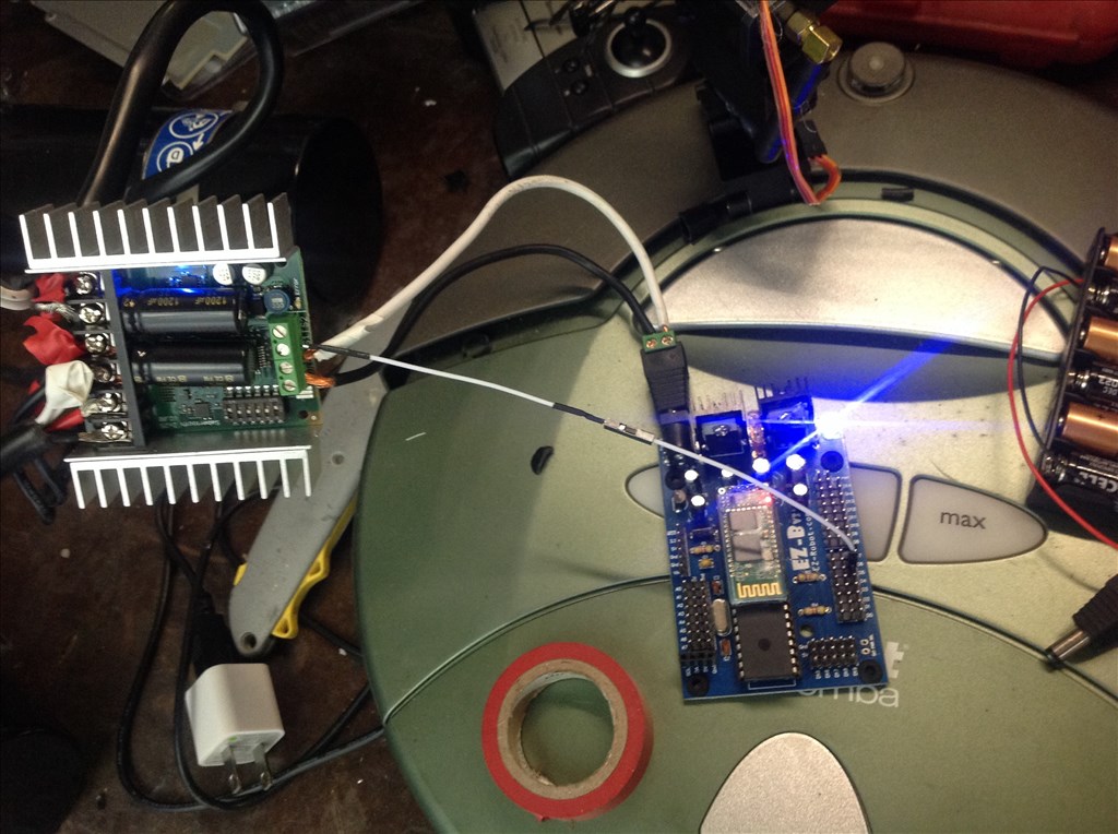
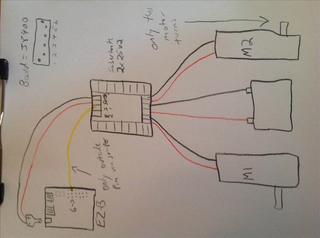
User-inserted image

User-inserted image


ARC Pro

Upgrade to ARC Pro

Join the ARC Pro community and gain access to a wealth of resources and support, ensuring your robot's success.

United Kingdom
#1  

Check the settings of the Sabertooth movement panel.

The Sabertooth uses 1-127 for motor 1 and 128-255 for motor 2 with 0 being used to stop both motors.

So set motor 1 full forward as 127, full reverse as 1, motor 2 full forward as 255 and full reverse as 128 with the relevant forward and reverse values for left and right turning.

Your wiring looks correct from what I can see.

#2  

I was never able to power my EZ3 board with 5V... Maybe I never had enough current? Not sure... Anyway, do you have the dip switches set right for serial communication on the Sabertooth? I am using 1,3 6 ON the rest off... I am also using a SLA batt and not a Lipo or Li-ion...

United Kingdom
#3  

Ah good catch, I missed that part of his sketch.

Simple Serial is as so (according to the manual);

User-inserted image

#4  

Yep, 1,3,6 on and the rest off give you 38400 baud not using a Lipo or Li-ion battery...

#5  

Besides setting the DIP switches correctly also keep in mind the BEC in the Sabertooth supports a max of 1 amp.

#6  

Also I noticed the EZB docs says:

EZ-Robot suggests connect Sabertooth Motor Controllers in R/C mode. This allows the user to control the motor speed and direction with the Modified servo Movement Panel.

#7  

Thank you for getting back to me. I had zero problems getting the ez-b to power from the 5v output, I was somewhat concerned about just using the one white wire jumper rather than a black,red,white connector but you're both saying that seems ok.

I simply set the switches according to this post in tutorials:

https://synthiam.com/Tutorials/Help.aspx?id=173

showing this image:

User-inserted image

I will change to the 1,3,6 on settings you referred to. I do have a question for you Rich, your image seems to show just the 2 as being off. Is this an additional setting or do you both think 1,3,6 will run both motors assuming I check and confirm the motor settings as Rich mentioned in the first reply?

I have to tell you I've had a heck of a time with micro controllers in general and the ex-b and your responses have just been really user friendly and I appreciate it.

If the above are correct can I ask how i'd go about finding ez-b information about setting a path without a line then programing the robot to follow it at a certain time? It will always be the same path assuming no obstacles to skirt.

I have many other components I can use from the ez robot kit and other items I have around.

Matt

#8  

Sorry Darathian, I replied before reading your responses.

By removing the brakes on the large jazzy motors I understood that I have effectively made them continuous rotation servos, is this not correct?

The tutorials I saw mentioned simplified serial but if RC is the way to go over bluetooth I guess I can do that, would it change the above recommendations?

As for the BEC output. Would you advise I add an external BEC? I'd like to avoid another battery pack since there is plenty of power from the motor batteries.

I'm also over my head some so please correct me if I'm looking at anything incorrectly.

Thanks again. M

PS: I should add that the Roomba is there just by coincidence. I'm still having a time with the ps2 connector project for that.

#9  

I don't know if you tried this, but you may want to try connecting each motor directly to the battery, one at a time to be sure that they both work. You might have a bad brush in the motor that is not turning. The wiring looks good from what I can see.

Good luck.

#10  

You know, I just blew up your picture and looked close at it; It looks like the second wire from the top isn't connected. It might just be the picture, but you may want to double check that.

#11  

@mdeming1

First I have neither the EZB or Sabertooth but here goes:

How you configure the Sabertooth depends on:

  1. How you want to do the control
  2. What your end goal is.
  3. What the Microcontroller in this case EZB supports

You have essentially 4 modes

Mode 1) Analogue Mode 2) RC mode Mode 3) Simplified serial Mode 4) Packetized serial

I believe and others can correct me that most people here use simplified serial or perhaps RC mode. I noticed that one entry on this page said https://synthiam.com/Tutorials/Hardware.aspx?id=26 said to use RC mode if you are using the Modified servo Movement Panel in ARC.

By RC mode I don't mean controlling the motors using an RC controller and receiver as apposed to serial or Bluetooth.

It really just means the Sabertooth will respond to RC type signals (pulses) just as if you were using servos. These RC type signals can come from a RC controller and receiver or a Microcontroller or anything else that could generate an RC type pulse.

If you use simplified serial you need to set the DIP switches correctly and based on the manual: 1,3,6 on rest off unless you use a lithium battery then 3 should be off it seems.

Per the manual:

"Switch 3 of the DIP switch block selects lithium cutoff. If switch 3 is in the down position as shown the Sabertooth will automatically detect the number of series lithium cellsat startup, and set a cutoff voltage of 3.0 volts per cell."

Also:

"Sending a character between 1 and 127 will control motor 1. 1 is full reverse, 64 is stop and 127 is full forward. Sending a character between 128 and 255 will control motor 2. 128 is full reverse, 192 is stop and 255 is full forward. Character 0 (hex 0x00) is a special case. Sending this character will shut down both motors."

Some of this information has been provided by others I just tried to combine it all.

Since I have neither devices currently I will let others who have used both provide more detailed answers.

#12  

One other thing:

Looking at your post again it says you used the joystick control.

Since I do not have an EZB or Sabertooth perhaps DJ or someone else can confirm but it looks to me like it might be sending servo pulses in that control.

If that is true I would think RC mode on the sabertooth would be needed.

#13  

The note to use RC mode is old. Use simplified serial for better EZ-B v3 support.

Alan

#14  

@thetechguru

Thanks for clarifying the RC versus simple serial question.

#15  

@mdeming1

If you set the sabertooth to simplified serial per the instructions and use just the sabertooth control in ARC does the motors work correctly then?

#16  

Hi all and thank you for all of your help. I was able to independently test the motor and it is good. I have not had the chance to get back to the robot to test the s.serial settings and probably won't until late tonight. I'll post back then and hopefully that will solve this particular issue. I'll let you know asap. Matt

#17  

Ok so here is the update. Set switches to 1,3 & 6 on, the rest off. The ez-b gui has the correct settings on the sabertooth motor controller relating to two motors forward, rev, right, and left using 1-127 & 128-255 respectively there are no boxes for stop however. This may not be a problem but I cannot get the motor to stop turning (again, mine is a modified servo full 360 either direction) I plugged motor two into motor one slot and it worked couldn't get both to work together. It may be the sabertooth and in don't mind sending it back, I'd just like to be sure there is nothing I'm missing on ez-b before I do. I'm not utilizing signal 2 on the sabertooth, just s1 jumping to d6 on the ez. Since this is two motors am I supposed to use both? If so I only have the option to use one ez-b connection in the drop down. Hope this makes sense. I'm using Bluetooth if this matters. M

#18  

Sounds like you have everything correct (you confused me by calling your motors "modified servos". they are not. A modified servo is a different animal entirely, they are just motors).

Only thing you might want to try (and this doesn't really make sense with the symptoms) is to power your EZ-B independently rather than using the 5v BEC of the Sabertooth. The 5V BEC is only 1 Amp which is a little low for the EZ-B (although with nothing else being controlled should be sufficient) and the EZ-B actually runs a lot better on 7.5 volts than 5 (although again, shouldn't really be an issue with only one connection). If you do this, be sure to tie your grounds together or it definitely won't work.

The S2 is used when using the Sabertooth in R/C mode (you connect one signal to S1 and 1 to S2 and treat them as servos with a regular movement panel) but Serial mode has been much more reliable for users since DJ created the Sabertooth control panel.

Alan

#19  

Are you using the modified servo Movement Panel or the sabertooth movement panel? To stop both motors in a script you would use sendserial(D6,38400,0)

#20  

Ok so I contacted sabertooth and the lady said to set all pins on except for #4 and voila both motors spun free (albeit independent of ez-b control and I got the proper voltage from the s1 connections so I've ruled out sabertooth broken. Should I use a ground &5v wire to d6 along with the signal jumper I have now? I'm using the sabertooth controller on ez-b for movement with pins 1,3&6 on the rest off. Is there another pin setting I can try? I have not independently powered the board, I have to dig up some fresh batteries tomorrow. I'm sure this is an easy something I'm missing. Both components have been really well made and easy to use.

Any additional ideas?

Thanks Matt

#21  

one more update. I powered the ez-b separate from the sabertooth 2x25 and grounded properly. I also used two much smaller motors for grins. Still the same thing. Only one motor turns, the other does not. I tried a few different baud pin settings. Some would have the one motor spin when I clicked on stop or similar.

Has anyone had luck with other pin settings? I'm sort of at a loss.

thanks Matt

United Kingdom
#22  

Have you tried using EZ=Script commands to make the motors start and stop? Something like;


#Stop both motors
SendSerial(D6,38400,0)

#Spin motor 1 full speed reverse for 1 second
SendSerial(D6,38400,1)
Sleep(1000)

#Spin motor 1 full speed forward for 1 second
SendSerial(D6,38400,127)
Sleep(1000)

#Stop motors
SendSerial(D6,38400,0)

#Spin motor 2 full speed reverse for 1 second
SendSerial(D6,38400,128)
Sleep(1000)

#Spin motor 2 full speed forward for 1 second
SendSerial(D6,38400,255)
Sleep(1000)

#Stop motors
SendSerial(D6,38400,0)

If that works correctly then the problem is in the config for the Sabertooth Movement Panel. If it doesn't work then the problem is with the wiring or the setup of the Sabertooth.

The pin settings should be as shown on the Sabertooth help page. This should put the sabertooth in Simplified Serial mode with a baud rate of 38400.

It shouldn't make any difference but you could also try on a different digital pin, D0 for instance.

#23  

I thought that on the V3 board that only D0 was the serial port.

#24  

I have 2 sabertooth 2 x 5 controllers running (via serial script commands) just fine from ports D1 and D7 on my EZb 3 board...

#25  

Thanks for that info Richard R I will update my mental notes.....

#26  

D0 is the only port that can drive a particular H-bridge. I believe the BV1113 or something similar (it is the one EZ-Robot used to sell before they started selling the much better 2.5amp h-bridge listed in the store now).

Alan

United Kingdom
#27  

Firmware updates have improved the EZ-B V3. Some were before my time with the EZ-B however I can confirm that all 20 digital ports are capable of Serial Communication.

Quote:

Serial Every digital port of the EZ-B Robot Controller can transmit serial data. Serial Communication is the process of sending data one bit at a time in a sequence. Serial communication is common with many peripherals because it allows commands to be transmitted over one wire. The transmission works similar to morse code.

The Sender and Receiver need to be configured for the baud rate (speed) in which the data will be transmitted. Common baud rate speeds are 300bps, 4800bps, 9600bps, 19200bps, 38400bps, and 57600bps.

Example peripherals for serial communication are LCD Screens, Motor Controllers, servo Controllers, Computer Communication, Arduino Communication, iRobot Roomba and more.

#28  

I haven't used script. I'll try to paste that program in later and let you know what happens. I'll also post another photo just to be sure nothing on my end is being missed. i'm positive this is user error of some sort on my part. I really appreciate everyone's patience helping me out.

more later. Matt

#29  

Well, the script didn't work so I played with it some more and used D0 and everything worked fine, go figure. I initially used D6 because I think I saw someone elses project or maybe a tutorial using D6. Supposedly my firmware is up to date but I'm a pretty early adaptor of EZ-Robot so it is probably an old board. It's funny. I got the EZ-Robot kit for Christmas two years ago and set to work on the Roomba. Unfortunately I got a random bad battery pack. Ez-Robot replaced it straight away (great customer service) but I had other projects come up in the meantime and had a devil of a time with the ps2 connector because A) I'm a bad solderer and B) all the old mouse ps2 connectors I had were covered in epoxy that made it difficult. I'm proud to say that I ordered two custom ps2 wires to get that Roomba robot project going sometime! Meanwhile, this current robot is the whole reason I got the board in the first place. I'm hoping to implement:

Map following IR control Action to take a certain times (a clock or date time function)

I'm going to see what I can do to add these functionalities and I'm certain i'll need your assistance again. I really appreciate everything. Not sure why only D0 works but i'll take it.

best Matt

I can only choose one resolver but since this was a group effort i'll offer thanks for resolution to: Rich Richard R Darathian Danger! thetechguru RobotDoc

Thanks for not giving up on my issue.

#30  

Thanks for clearing this thread up. I've got 3 V3 boards and none of them will spew out sendSerial commands on any port but D0. Of course my V3 boards are somewhere between 2 and 3 years old.

EDIT*

The D0 port testing I did on all 3 EZ-Bs was confined to the 57,600 and 115,200 baud Roombas. The Roomba commands will not work on any other digital ports on any of my V3s. I have the latest firmware flash on all three boards.

United Kingdom
#31  

Both of my V3s will send serial commands on any port, at least to my serial LCD displays.

I never looked in to it much as it is something I cannot afford to get interested in but D0 is the only port the Roomba can use and I believe it may be due to the baud rate (I can't afford to get in to the whole Roomba thing as they are ridiculous money over here). However, @Anthony is using multiple Sabertooth's (Saberteeth?) with Lexi and I believe @Dave may also be using multiple Saberteeth on his B9 (I may be wrong on that one) so they should work on any Digital port.

FYI, if you use the latest ARC you are forced to upgrade to the latest firmware too. As far as I know all V3s are pretty much the same (other than a few minor component changes) so all should use serial the same way. I will add checking serial and baud rates etc. on all 20 ports to my to-do list, it'll be a fun little project and be something to break up the mundane list of tasks I an fighting with currently:)

Glad it's sorted now though. As for the other questions, feel free to ask. Search the forums too, the time based one has been discussed/explained previously (however if you can't find it or need more specific help it's no issue, we are here to help).

#32  

Actually I'm only using one Sabertooth per EZB and I do have it attached to D0. Purely by chance. If I remember correctly I was having problems with the Sabertooth responding to serial commands at first and I had it connected to a different port. When I moved it to D0 I think that's when I started having success. I thought it was because I got the script right. It may have just been that I accidently plugged it into the only port that will send serial commands. blush However like @Rich I need to confirm this.

United Kingdom
#33  

I can confirm I have successfully used Port D14 for sending Serial commands to my LCD displays (my LCD examples project uses D14). These were at a baud rate of 9600.

I have also used D8 on my TellyMate examples, these were a baud rate of 57600.

While I don't have projects to confirm it, I do know (from memory) that I have used a whole range of digital ports for serial communications and not had any issues. To put it bluntly, I never really cared which port I plugged in to. The only serial issue I experienced was twitching servos (on other ports) when sending serial commands to my first LCD display (on both EZ-Bs I have and on multiple projects), I do not know if this was fixed as I changed the LCD to I2C so I didn't have to deal with the problem:)

I know D0 is the only port which had the ability to communicate at a specific baud rate...

Reading this post DJ explains baud rates a bit. Basically, the V3 maxes out at 57600 for all 20 ports with the exception of D0 which can do 115200. So if your baud rate was set to higher than 57600 this would explain why it wasn't working on anything but D0. If it was below 57600 then we are still none the wiser.

#34  

As mentioned earlier, my sabertooth(s) work on other pins (not just D0)... but I am only using 34800 as a baud rate...

#35  

For reference I'm posting photos of my V3 board. I was using the 38400 baud rate with the ez-b sabertooth interface (for sabertooth 5x25). It wasn't working both motors until switching to DO. The ez updated says my firmware is up to date.

Sorry for the wires. After solving the issue I had I decided to do my other functionality experiments on a smaller platform first so I got out an rc car and a smaller sabertooth [edit, this is not a sabertooth! it is an L298N chipset 2.5 amp motor controller available from ez robot store] had ordered from ez-b way back when and never opened. Haven't tested it out yet.

User-inserted image

User-inserted image

User-inserted image

#36  

@mdeming1... Good to hear... but that's not a sabertooth in the above picture... Looks like an H-bridge of some sort...

#37  

You're absolutely right, my mistake. There is a name for it, I bought it from EZ Robot and DJ has a control program for it. I'll find the name and edit. Thanks Matt

Edit here and above: the controller is an L298N chipset 2.5 amp motor controller available from the ez robot store