
This tutorial will cover some basics on using the ADC (Analog to Digital Converter) ports on the EZ-B v4. Included will be some information about the ADC ports, mention some of the peripherals that can be used with them, the ARC ADC controls you can use, and some script examples for you to look at and try.
Step 1. About the ADC ports.
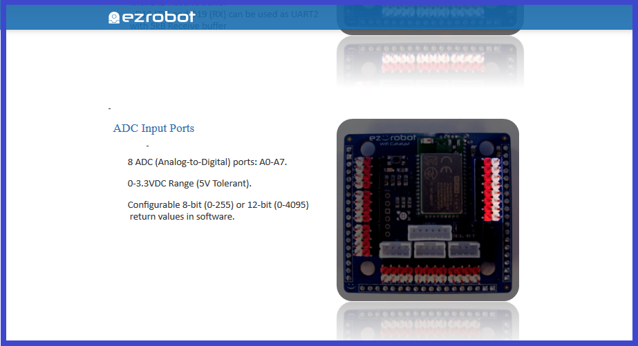
There are 8 ADC Ports on the EZ-B v4 numbered "A0" to "A7" that you can connect devices like analog sensors. Each ADC port contains three pins...
Ground: (output) located towards the centre of the board.
VDC: (output) The centre pin, regulated at 3.3 volts.
Signal: (input) The outermost pin from the centre of the board which reads the voltage between 0 and 3.3 volts.
The ADC ports are Configurable at 8-bit (0-255) or 12-bit (0-4095) in software.
In an ADC control found in the ARC software, such as "Read ADC", ADC reading intervals can be selected from 100 ms to 60000 millisecond analog values.
Analog readings are from 1 to 255 (0v to 3.3v) in 8 bit mode, or 0 to 4,095 in 12 bit mode.
To make sure you get reliable ADC readings using the EZ-B connected to the ARC software, the following list contains some popular troubleshooting techniques...
1) Make sure that you are supplying the correct power, to power any sensor that you want read (Remembering that the power output from an ADC VDC port is 3.3v),
2) That they are connected to the ADC ports correctly. Keep in mind that the layout of pins on some sensors may not match the same order on the EZ/B, so using an extension cable may not be adequate, and single jumper cables my need to be used.
3) The correct port is selected in the ADC control configuration menu,
4) Make sure that the sensors and cables are in good condition,
5) Adjust the "interval ms" in an ADC control (explained in the next step), to suit you and your sensors needs,
6) Use appropriate "Pull up" or "Pull down" resistors on your sensors where necessary,
7) Adjust any potentiometers that may be on the sensor itself, to dial in any sensitivity that helps get correct readings.
8) Slow ADC readings could be a result of network saturation, wireless interference, or could be due to your computers processor not working as fast as it should.
Something to keep in mind, is the more sensors you use simultaneously, and have the ADC reads set as maximum speed, this will use more processing power and could flood the WiFi network which will slow down response times.
The next step will explain the three ADC controls found in EZ Builder.

can this detect the audio for a jaw movement on a robot?
If you have a analog audio level sensor (has a microphone) hooked up to the ADC you can detect the strength of audio levels.
You may be able to run the audio from the speaker breakout on the EZ-B v4 or IoTiny to an analog pin, I've never tried it but in theory it would work. It's a 3.3V audio amplifier. Although, it might mess up your audio if you still want audio going to the speaker. Worth a try I suppose.