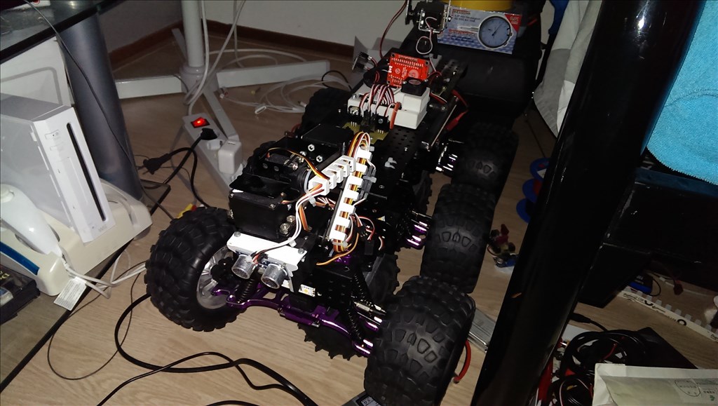
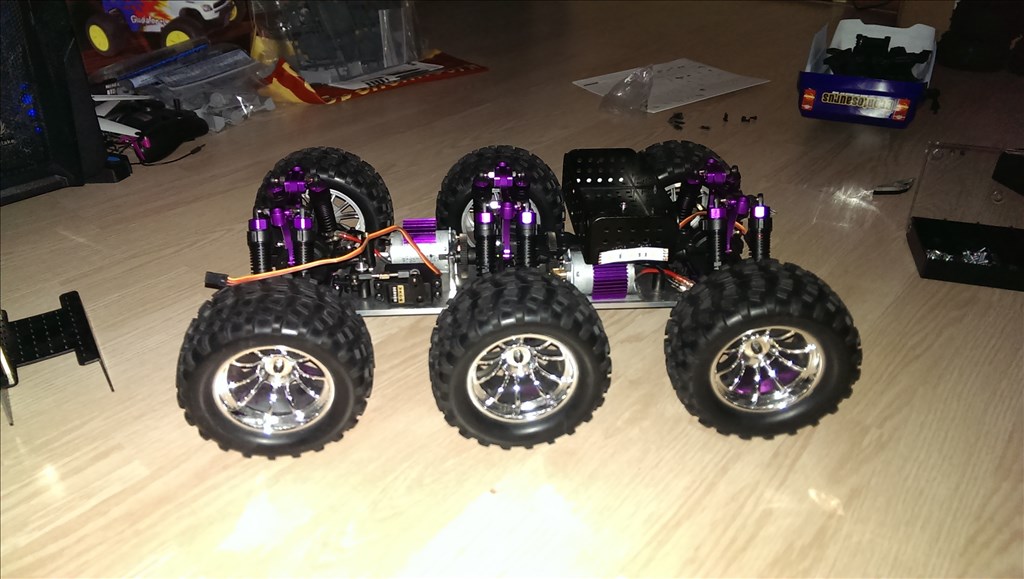
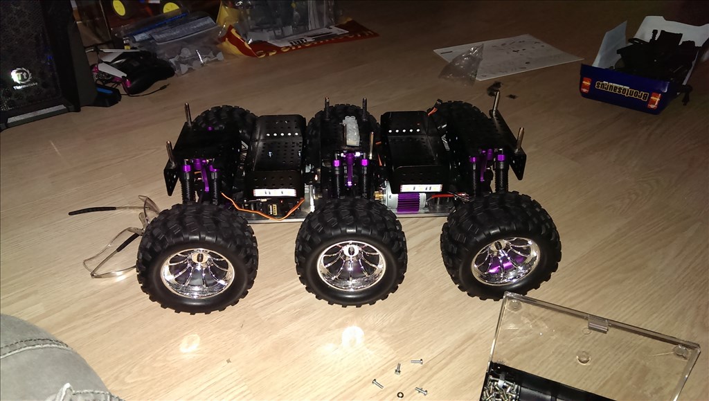


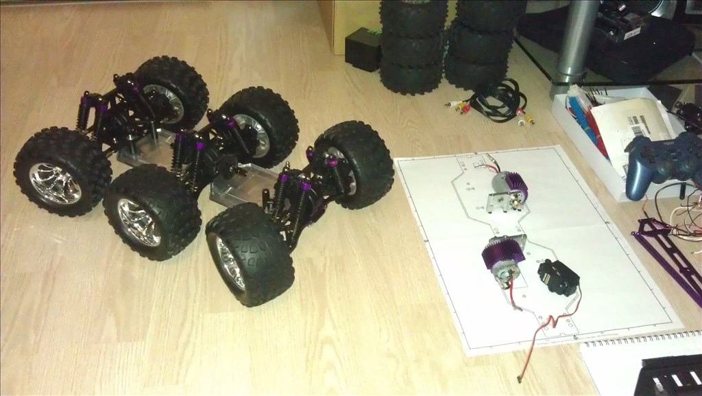
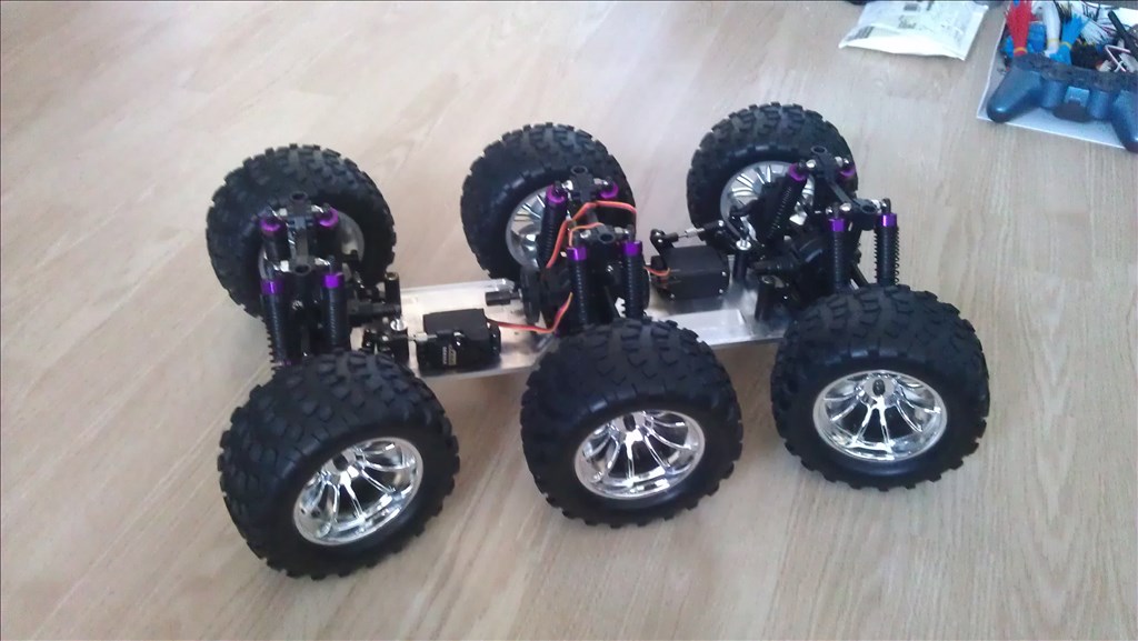
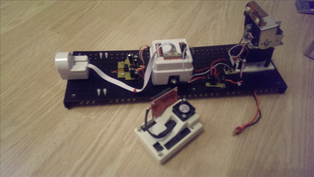
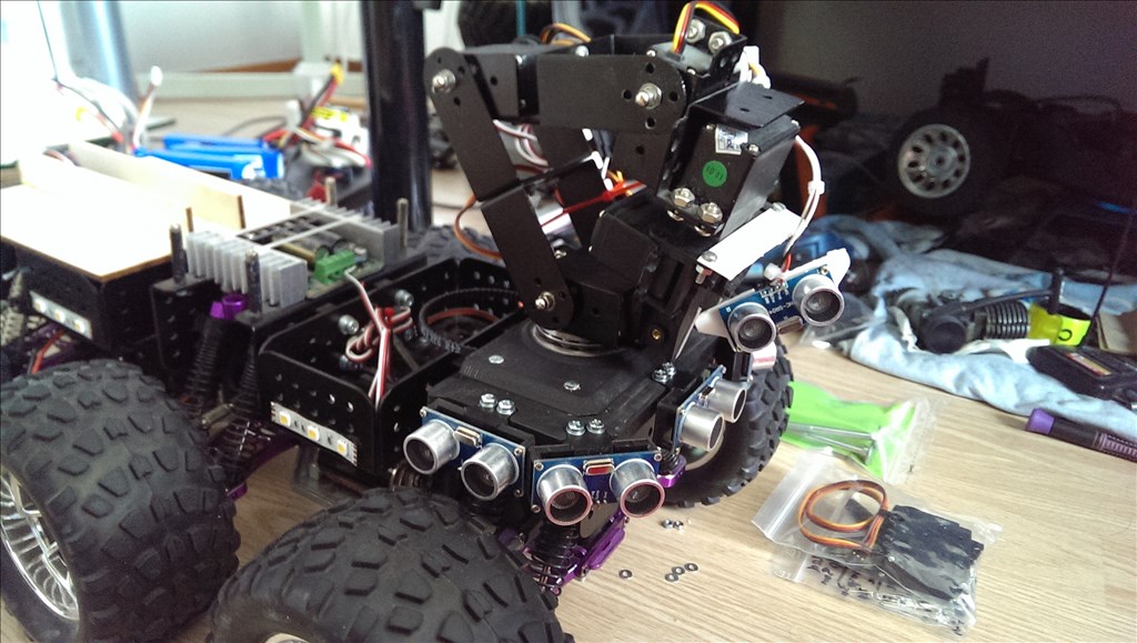

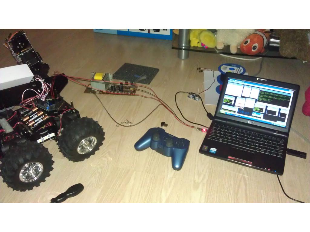
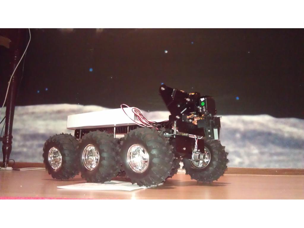
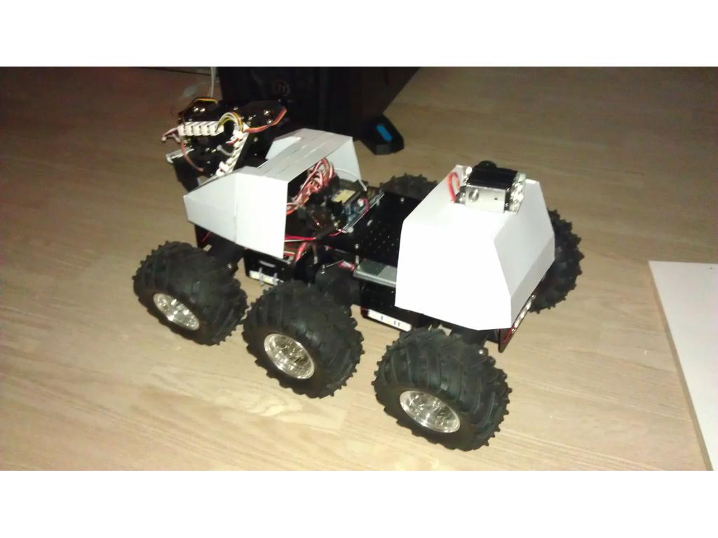
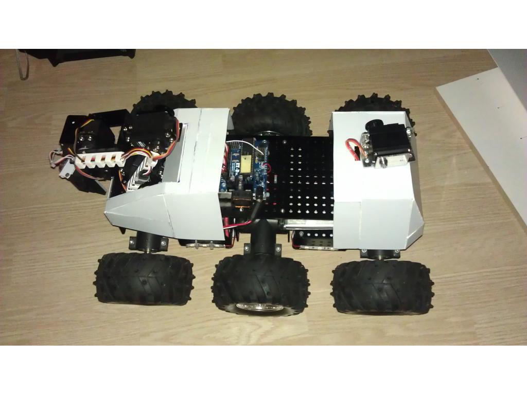
Hello fellow EZ-B'rs, As I finally discovery how to upload photos I thought it was time to share my robot with the world. It's called R.O.O.S.T.E.R which stands for: Remote Online Operating Scientific Testing Electronic Robot (took me about an hour to come up with that, but I like it).
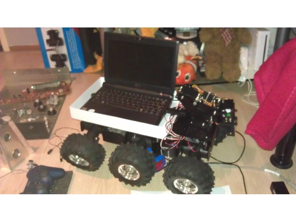
The specs:
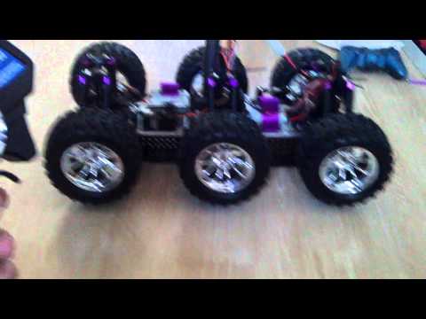
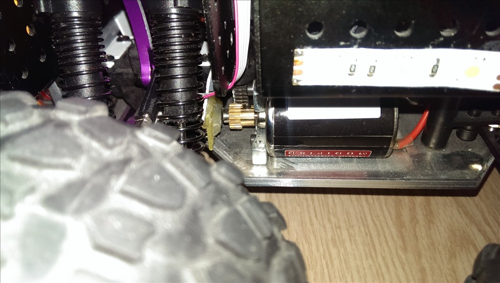
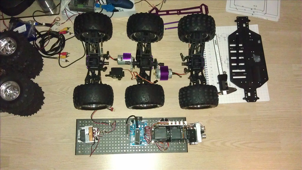
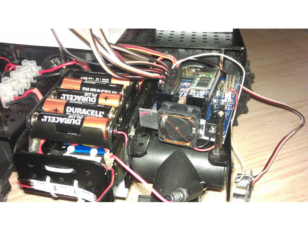
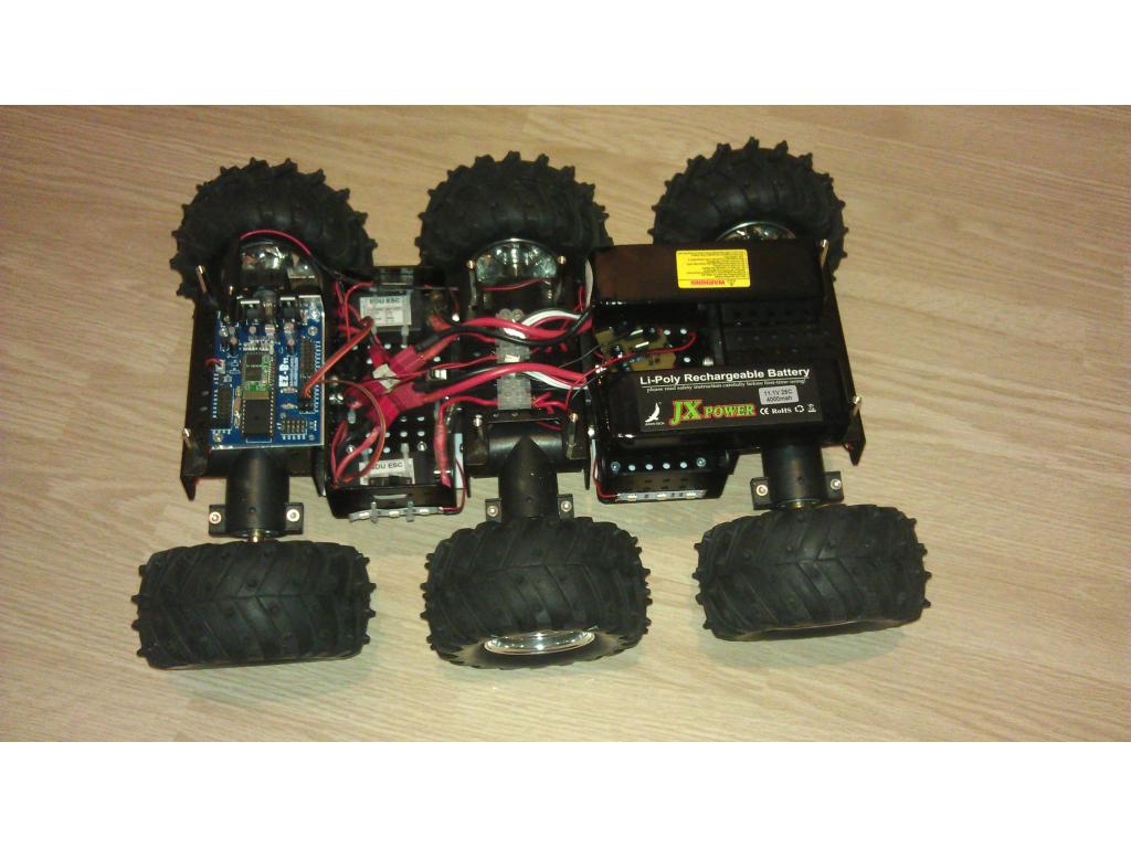
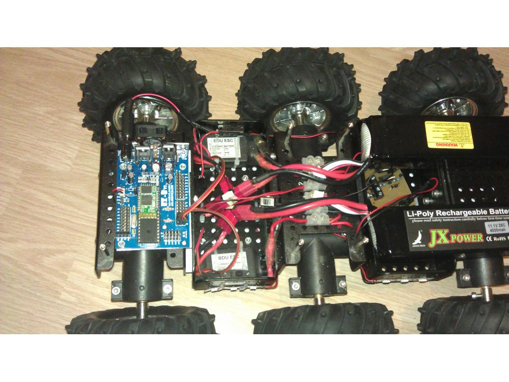
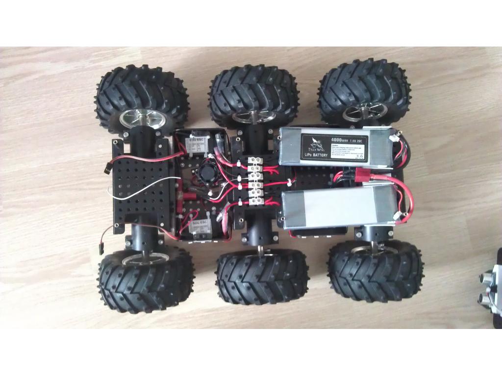
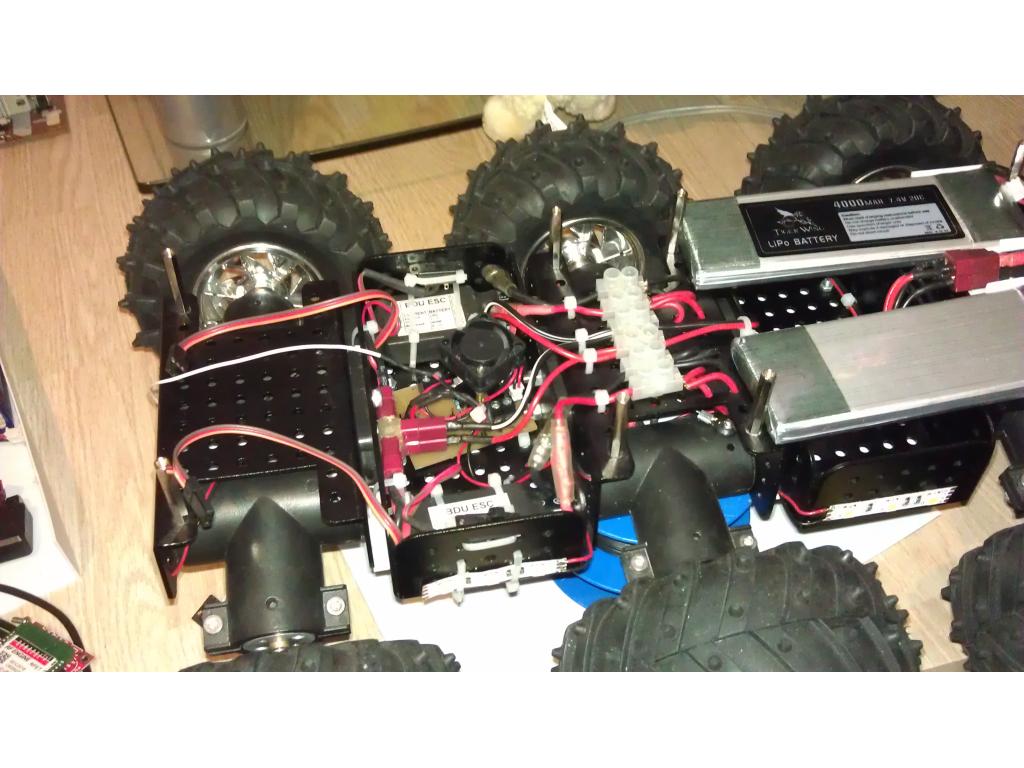
- 6x 6v 6A motors
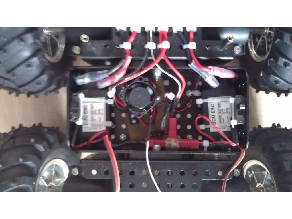
- 2x 20A Rc Car ESCs
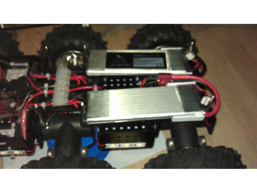
- 2x Reddragon 2s 25c 1200mAh
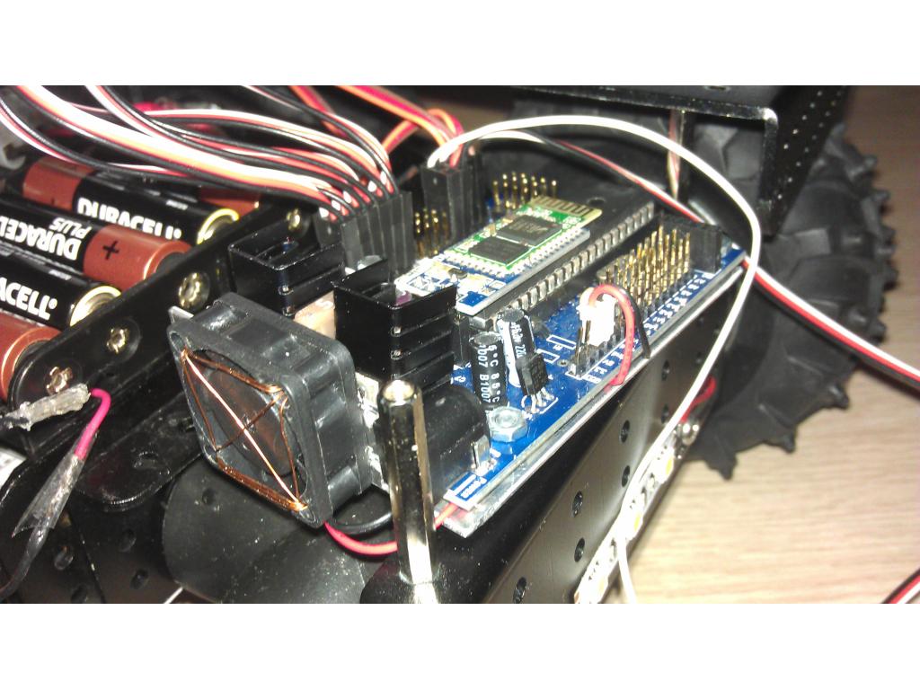
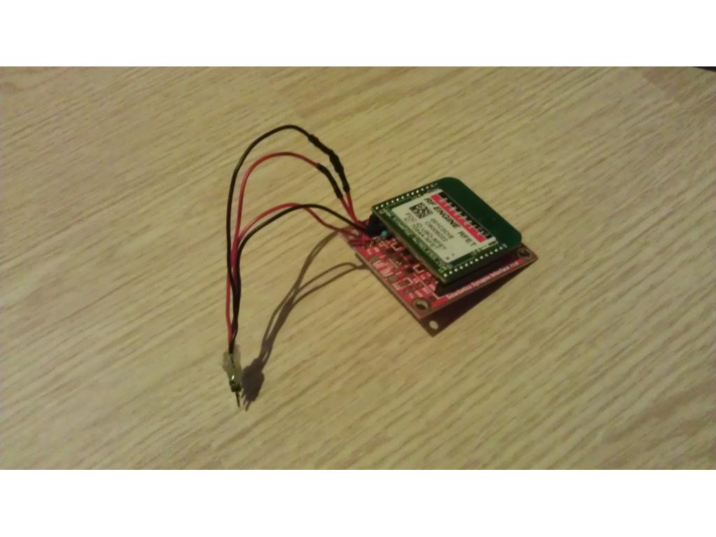
- Ofc the Ez- B
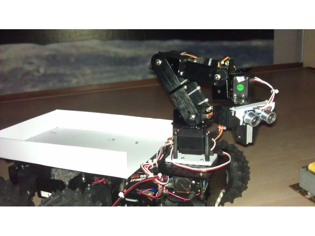
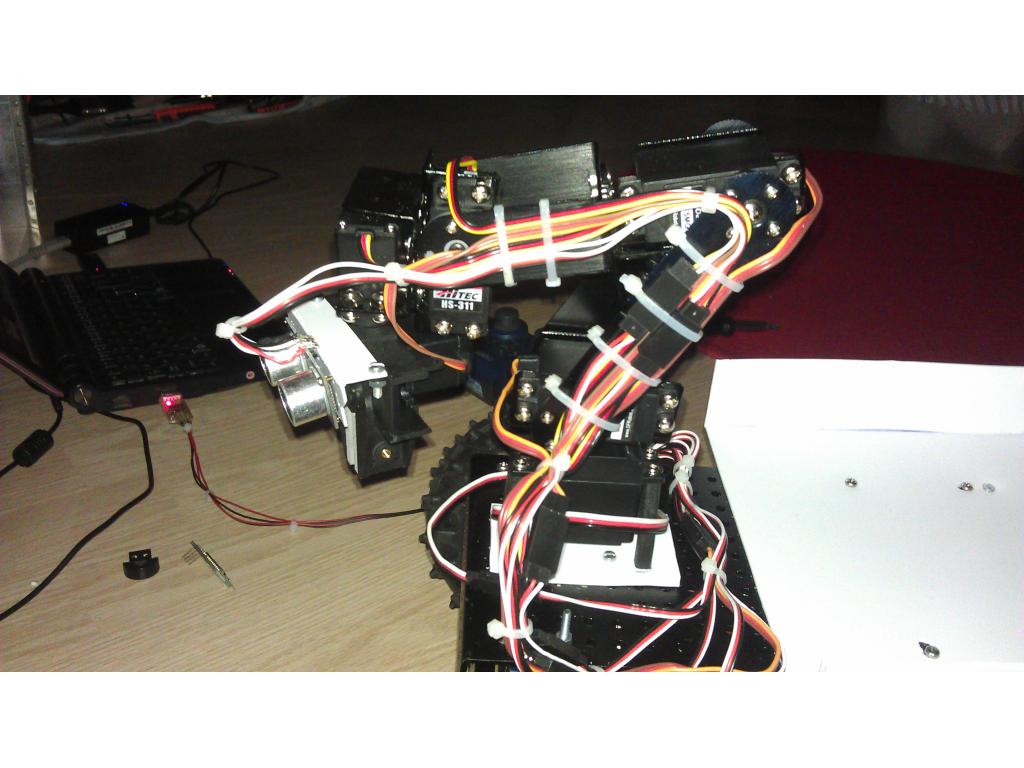
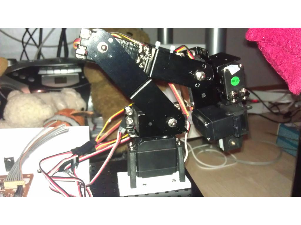
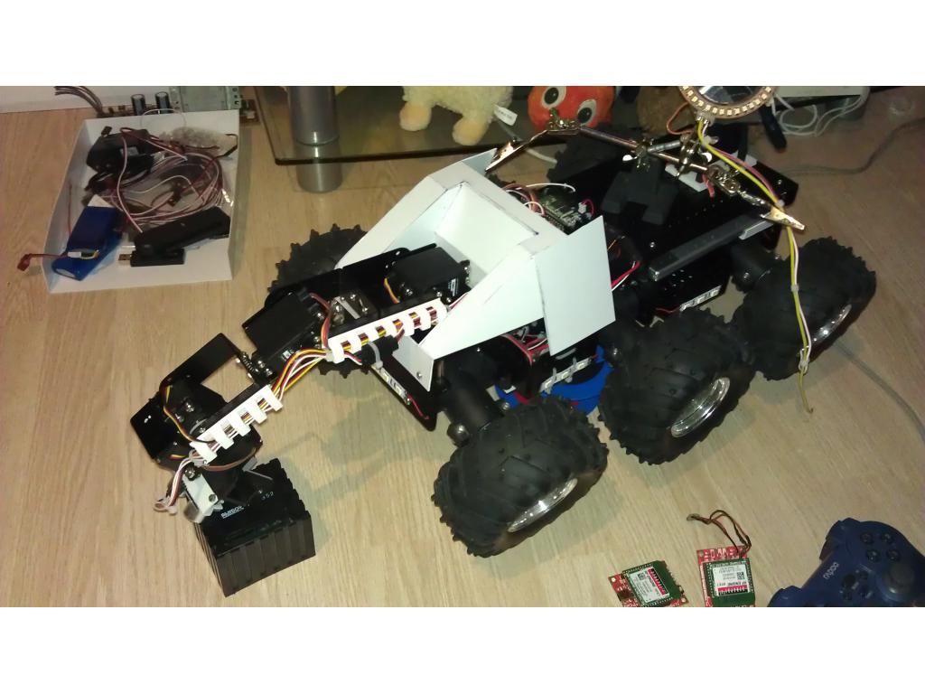
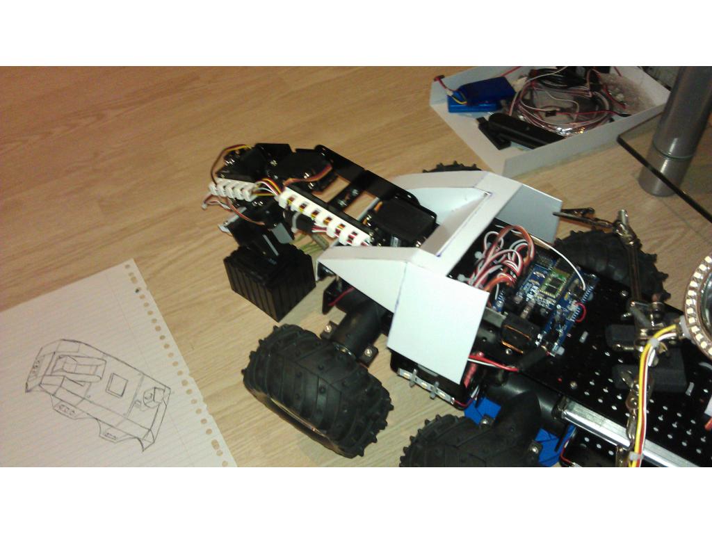
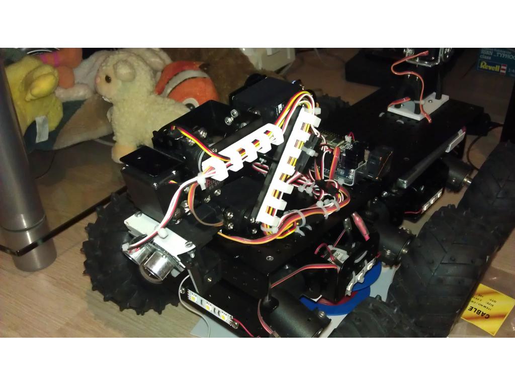
- Dfrobot 5dof robotic arm
- Asus Eee pc 900hd
- Ping sensor (well... I sort of broke it... It got stuck between the robot and the wall...)
Why I'm building it? Because I can, robots are Awsome, the EZ-B rules and I got tired of burning/shocking myself when I'm testing one of my "crazy" contraptions.
Up coming updates for robot:
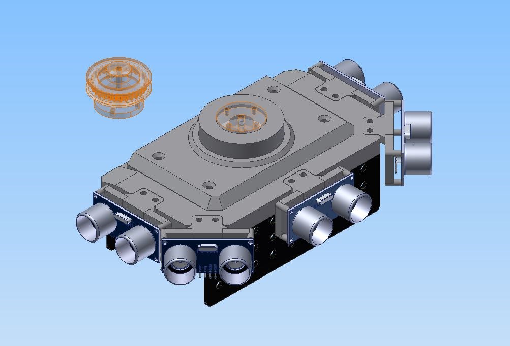
- A rotationplatform for the arm.
- 2 gigantic lipo batteries.
- camera+ pan/tilt turret.
- Small rockets
- mini mini-gun
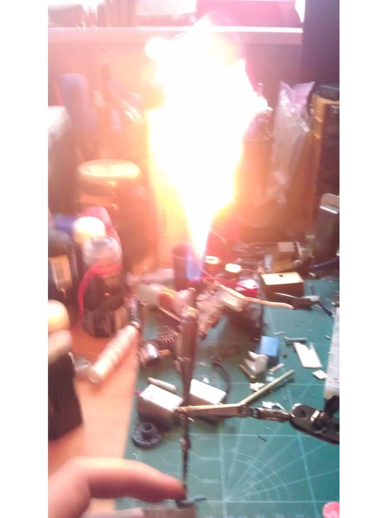
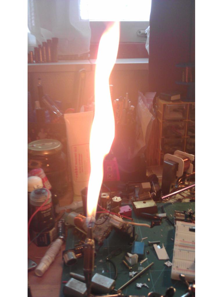
- Flamethrowler (a failed version of a liquid fueled rocket, but it's working if you call it something else)
- coilgun
- railgun
- Lots of other things I can come up with.
By budel0
— Last update
Discover more robots
Robohappy's Introducing....HEMI Or HHCB1 (Home Health Care...
HEMI home-health robot prototype lifts and transfers patients using high-torque servos, actuator, sensors, EZ-B control,...
Morbeious's My Printer Revolution Six
Custom Revolution Six robot dances after 3D printer and wiring fixes, ready for scripted dance routines.
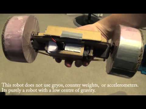
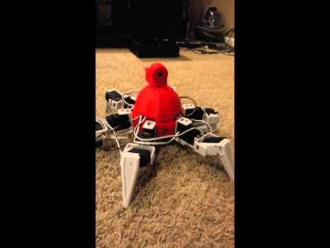
Cardboardhacker's Ez-Ollie
ez-Ollie: recreate Sphero Ollie with a simple low center-of-gravity build for stable rolling, easy forward drive and...

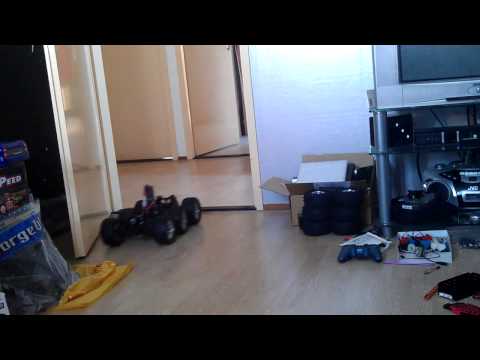
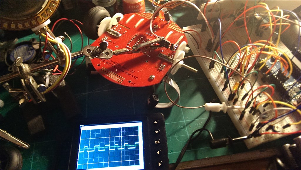
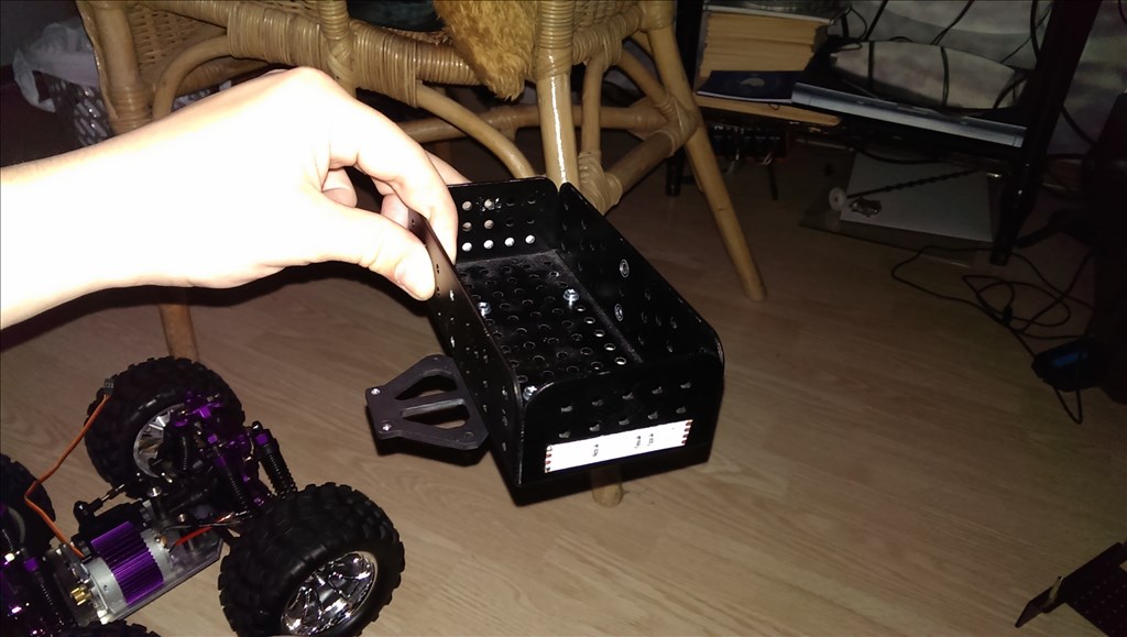
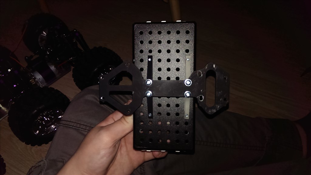
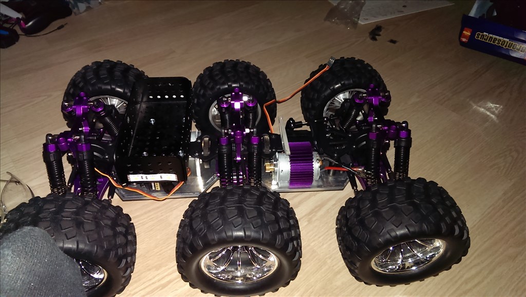
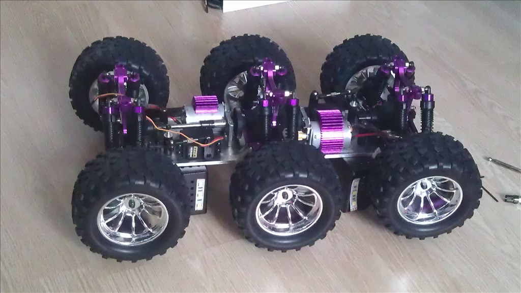
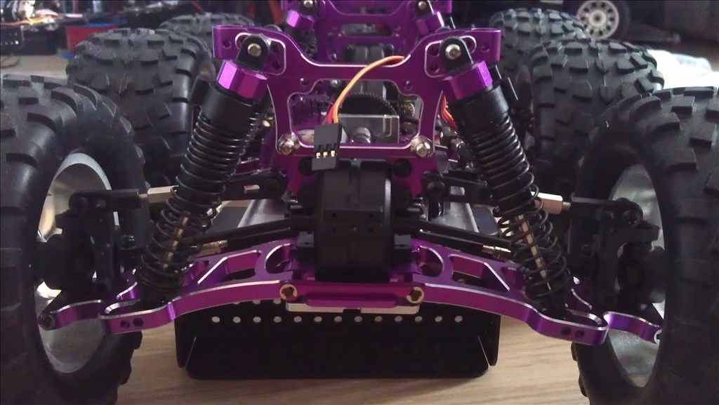
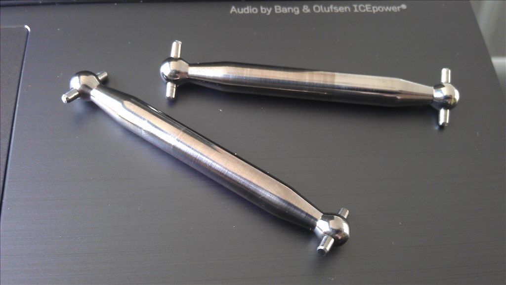
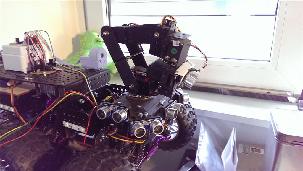
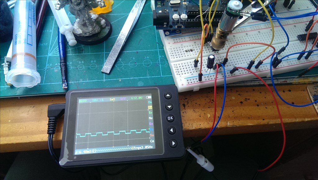
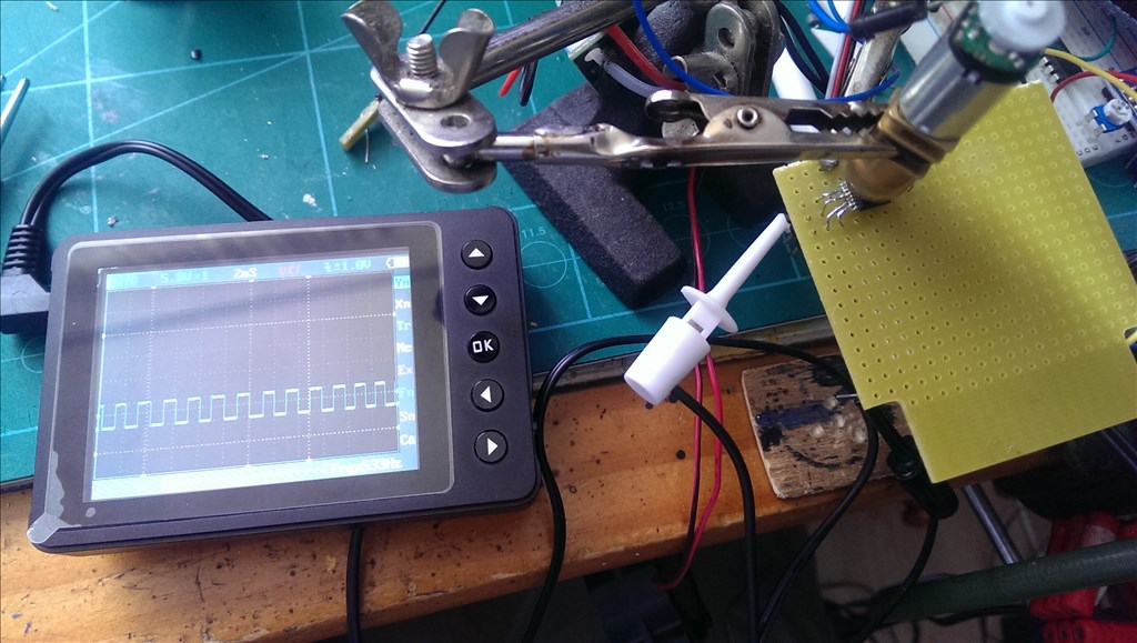
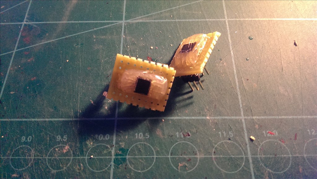
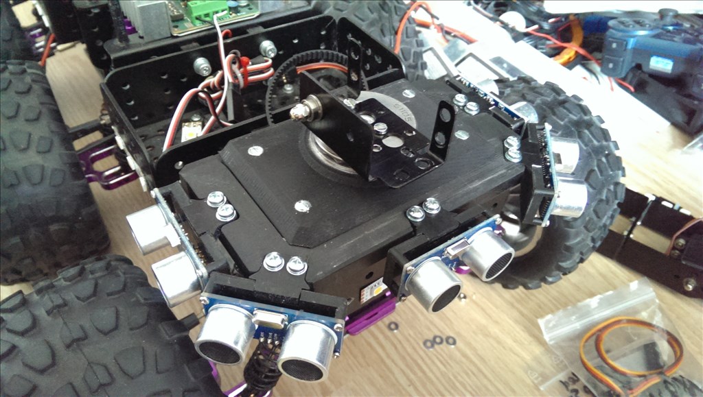
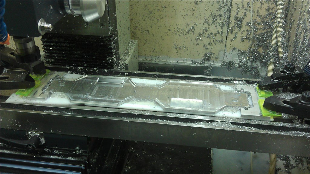
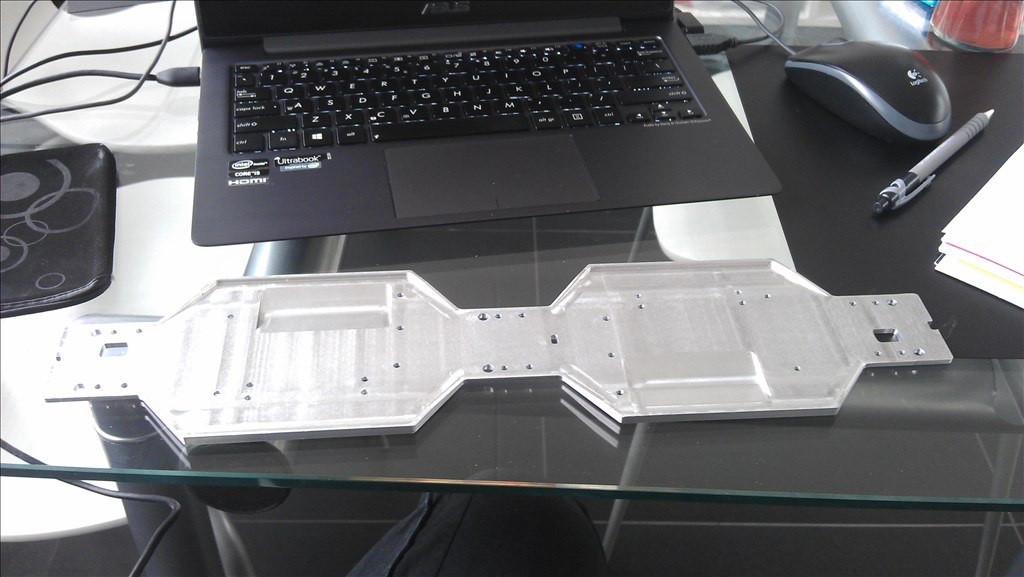
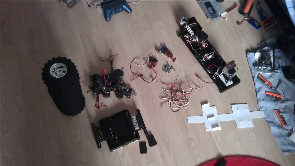
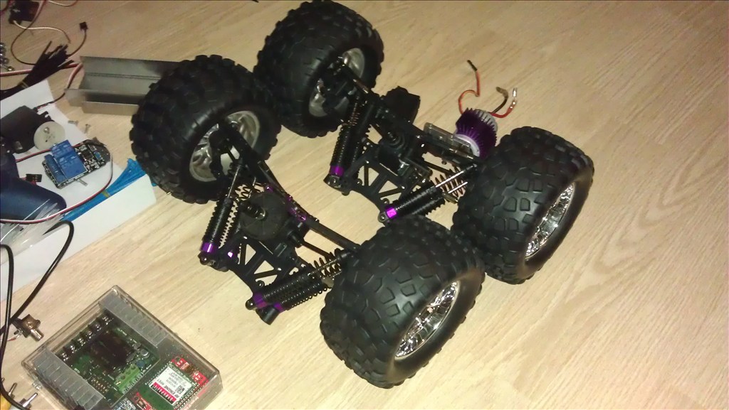
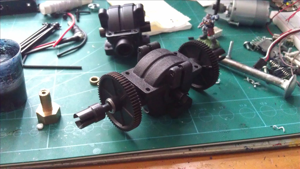
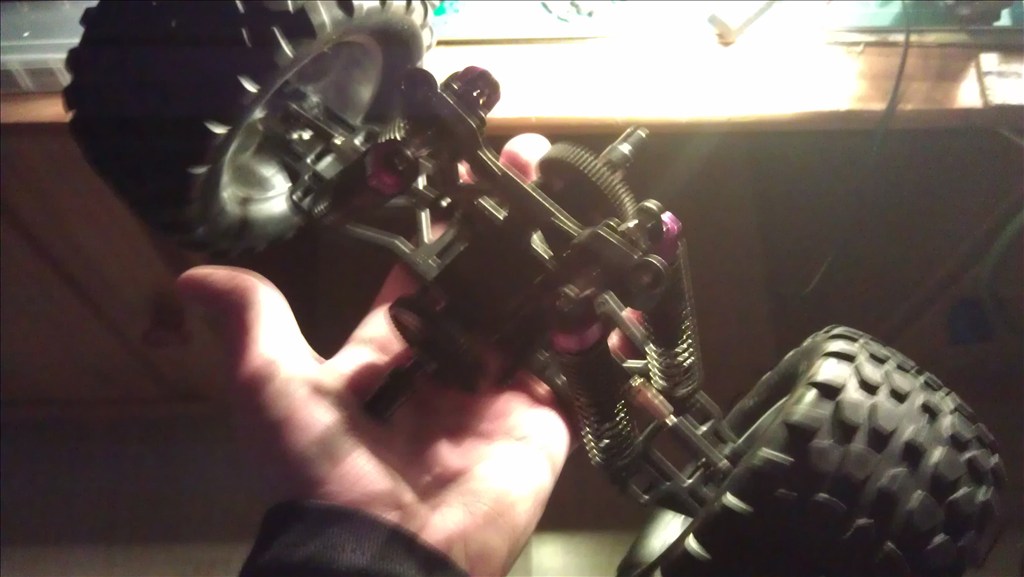
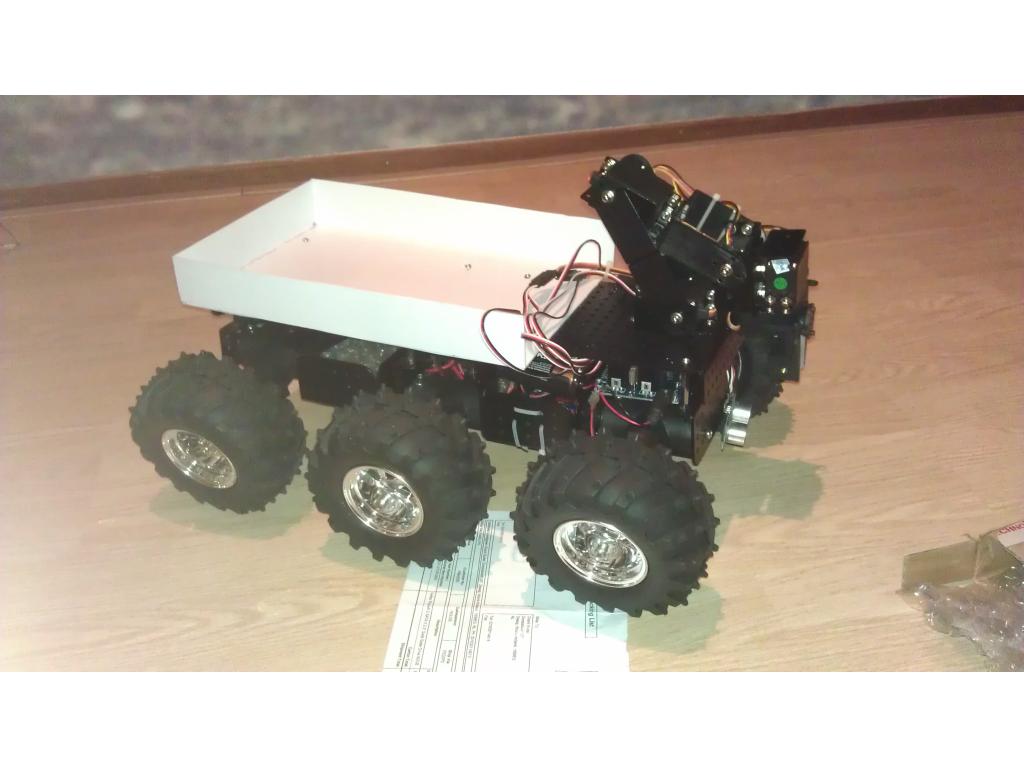
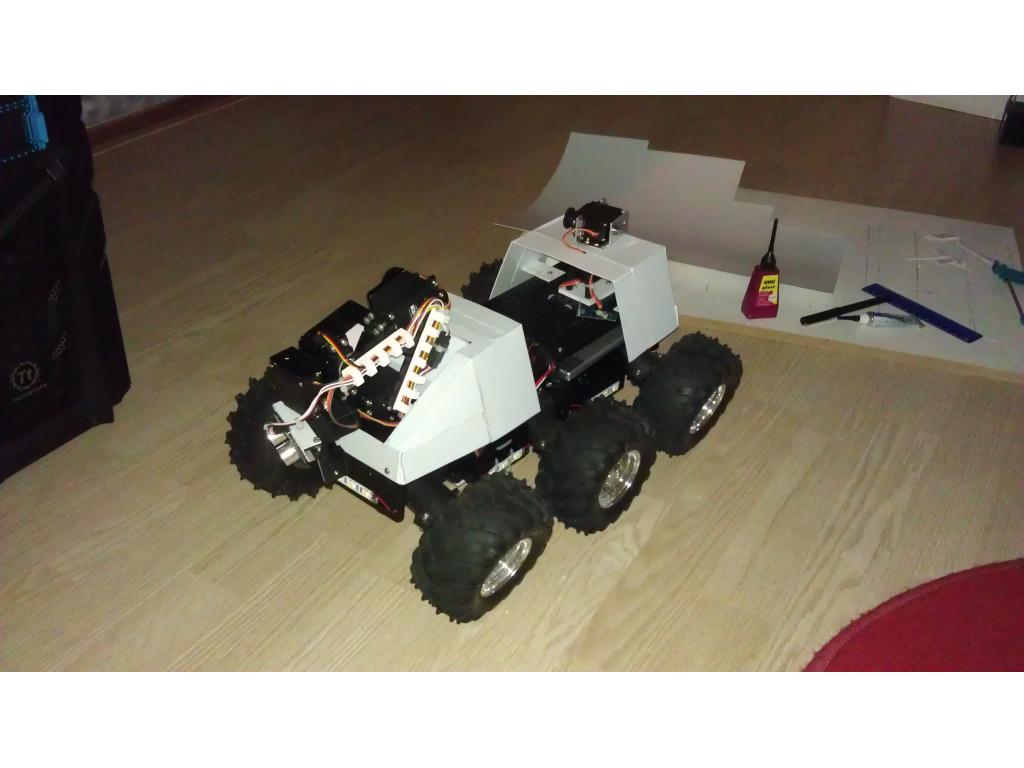
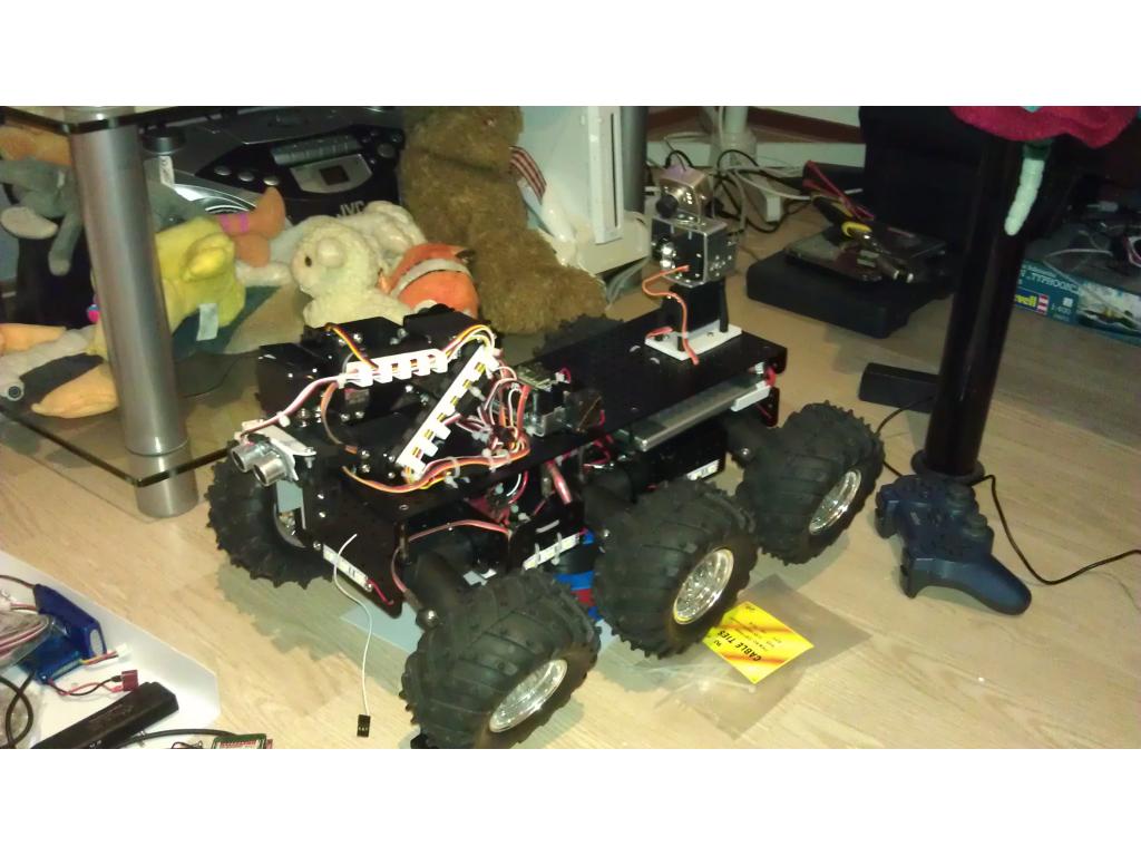
Some extra pictures.
that's a sweet looking bot
Very cool! That looks like it should be on the moon roving around
That arm is looking good
I'm really liking your bot! I was actuallyt looking at that platform a couple days ago. It's a little to expensive for my tastes, but would love to have one! Where did you get the arm? Can you post a link? Great work!
Oh thanks man! I've been working on it for quite a while now. I bought the robot arm from EBay. It's quite expensive though. But after doing lots of calculations and research I figured that if I'd just buy it as a set it would be cheaper for me. It depends in what country you live... If I buy something from outside the EU I have to pay 20% taxes over the complete amount I've payed including shipping when I receive it! If the object is over 20,-. And if I would buy it in parts I would probably go over that eventhough everything is cheaper outside the EU if you don't count shipping...
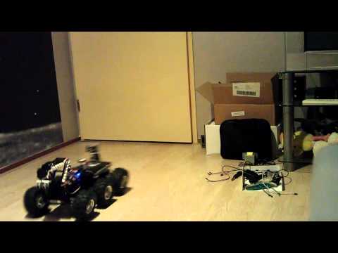
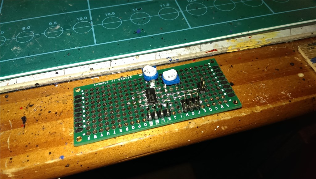
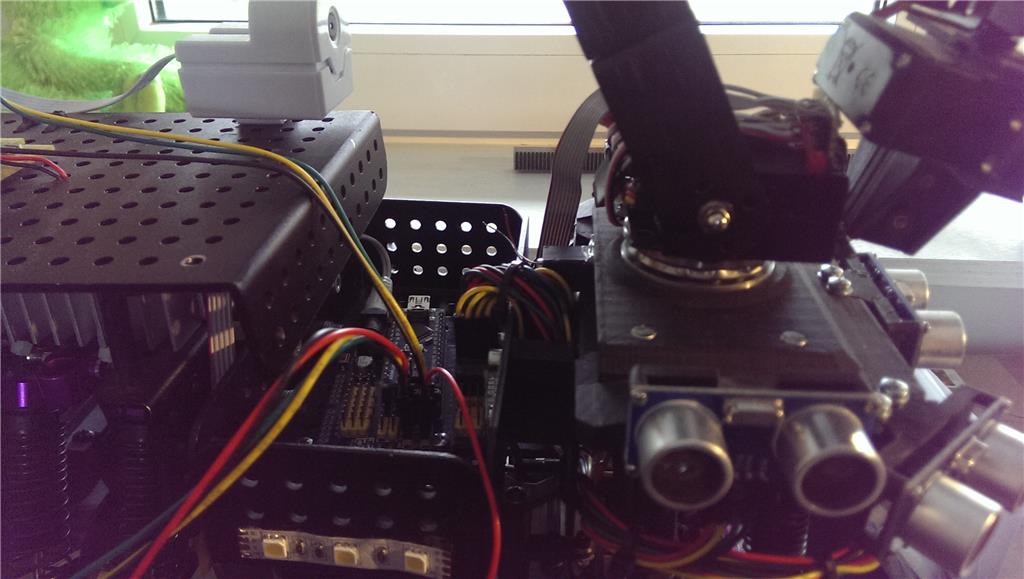
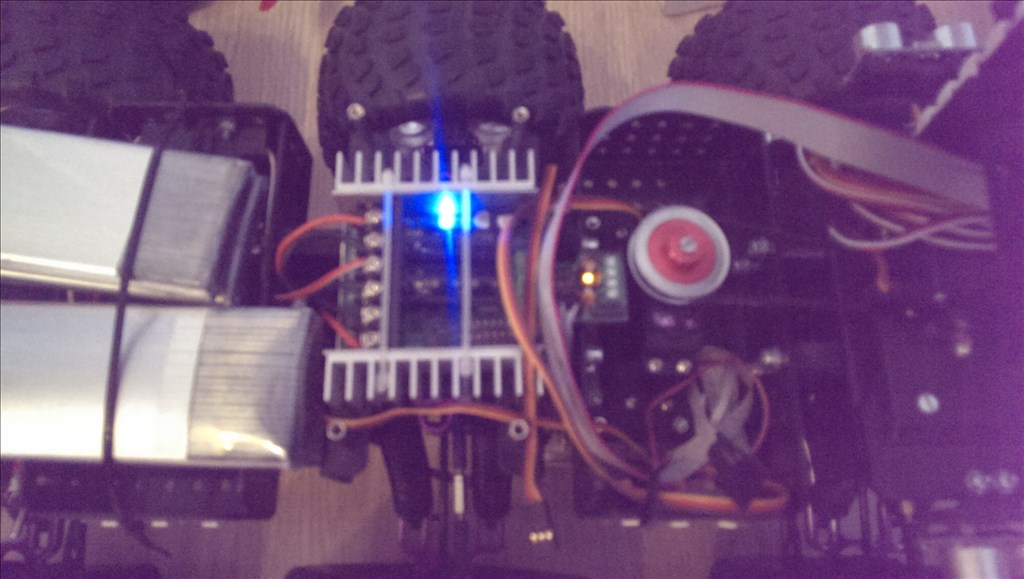
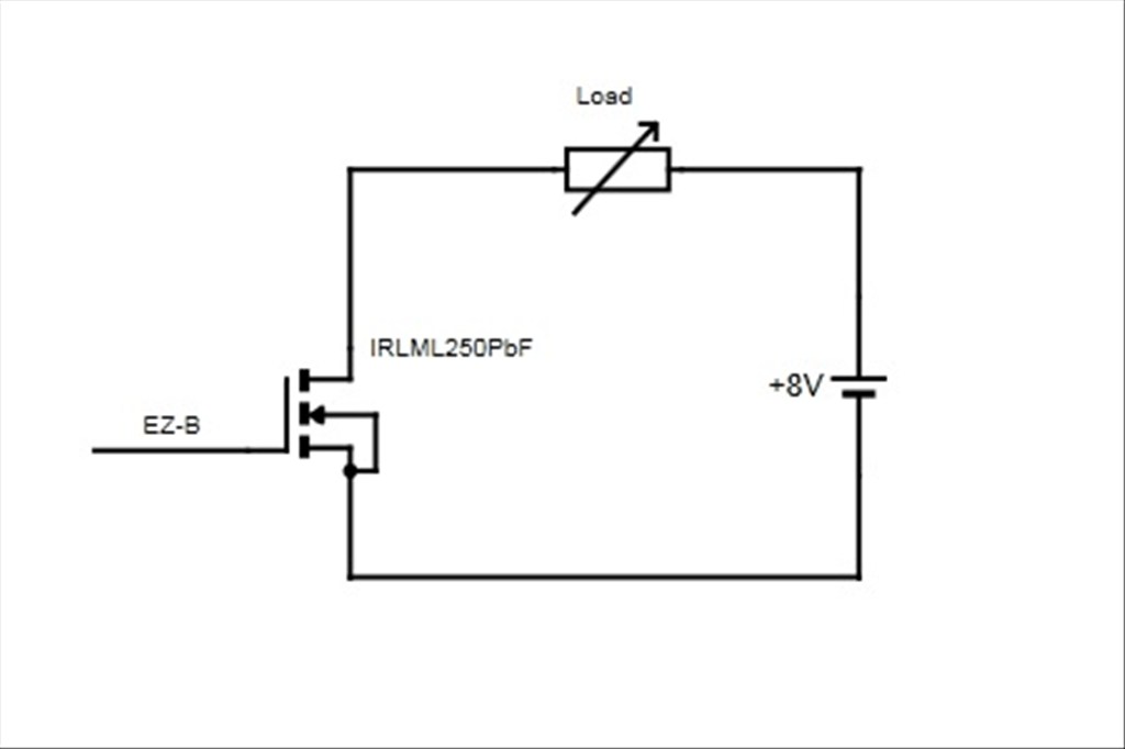
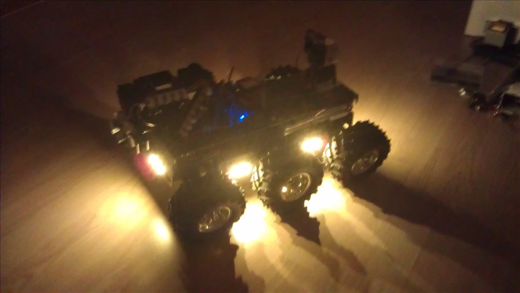
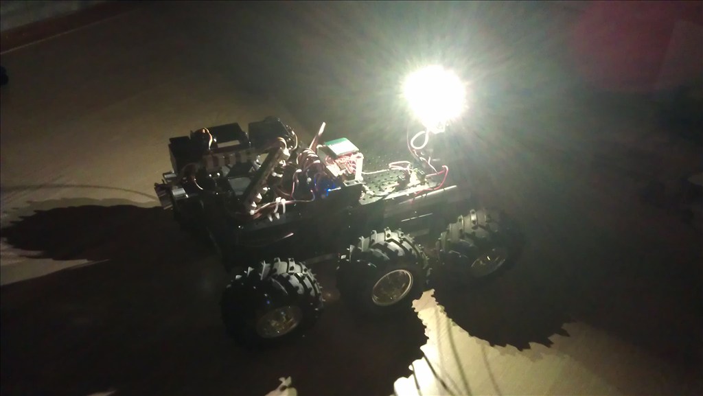
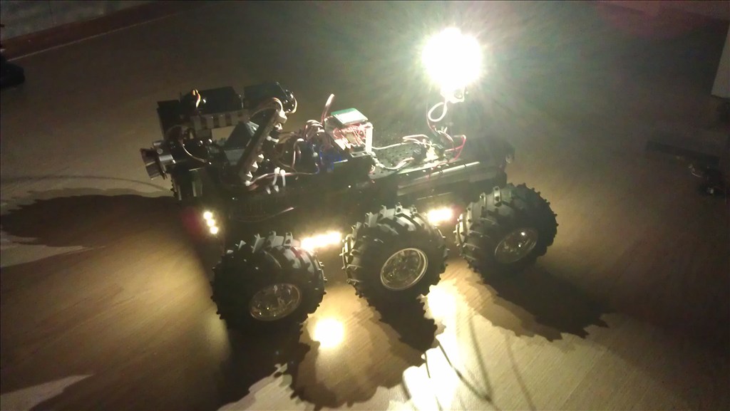
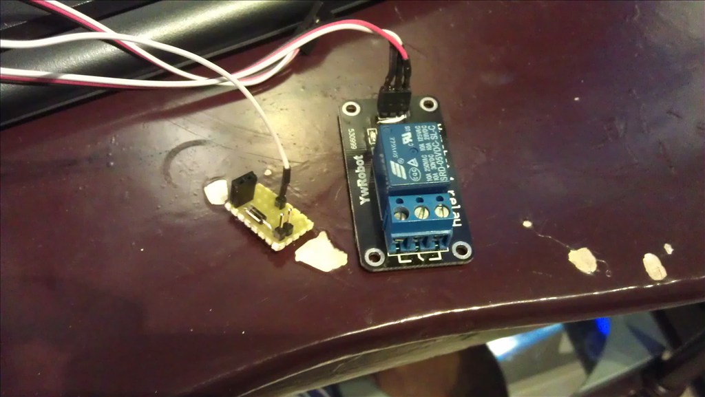
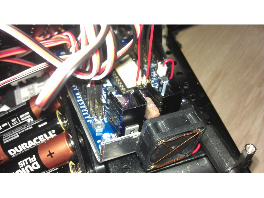
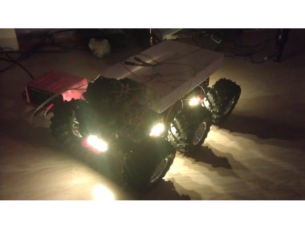
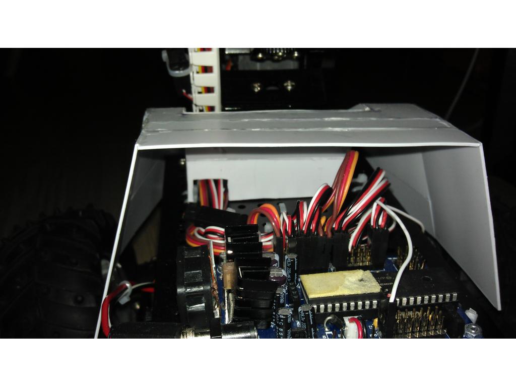
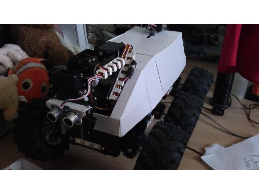
A few days ago my brother gave me a peace of LED-strip and a few LEDs, that gave me an idea.
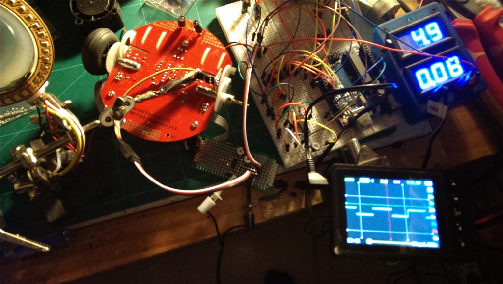
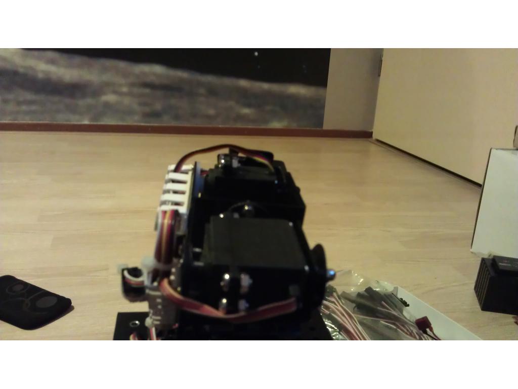
Nightmode:
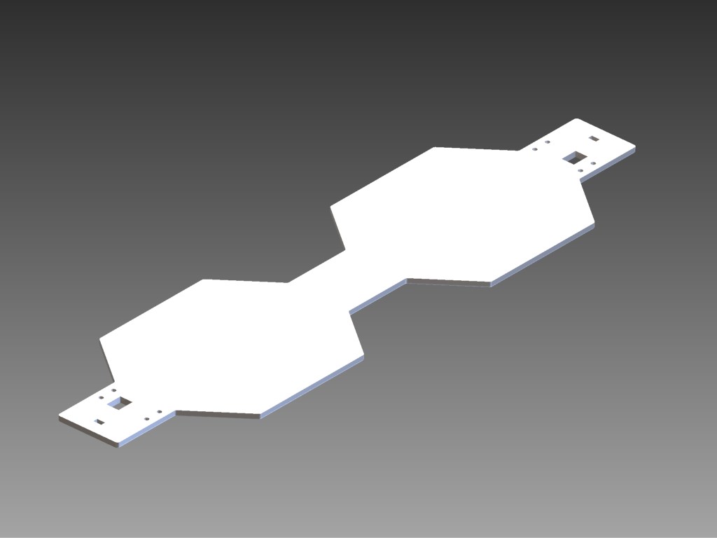
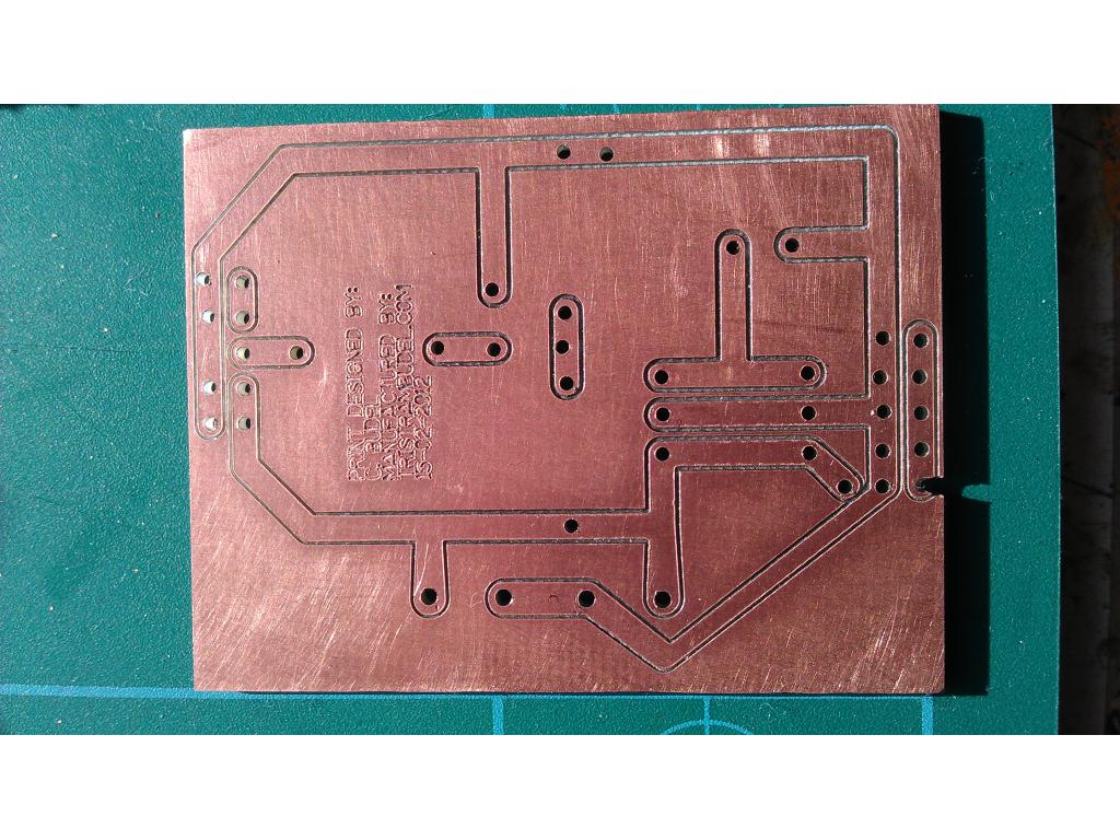
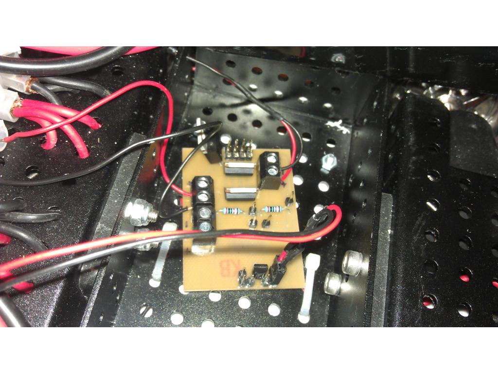
It's still in its testing phase and I still have cleanup the wiring, but it looks cool. I might even design a small board to distribute power from my Lipos to everything. More coming soon!
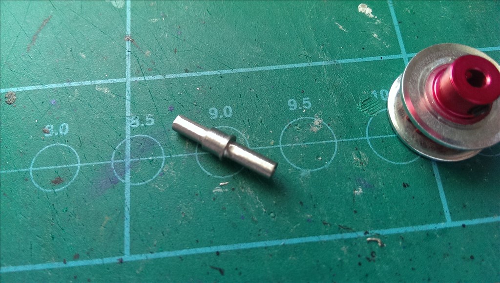
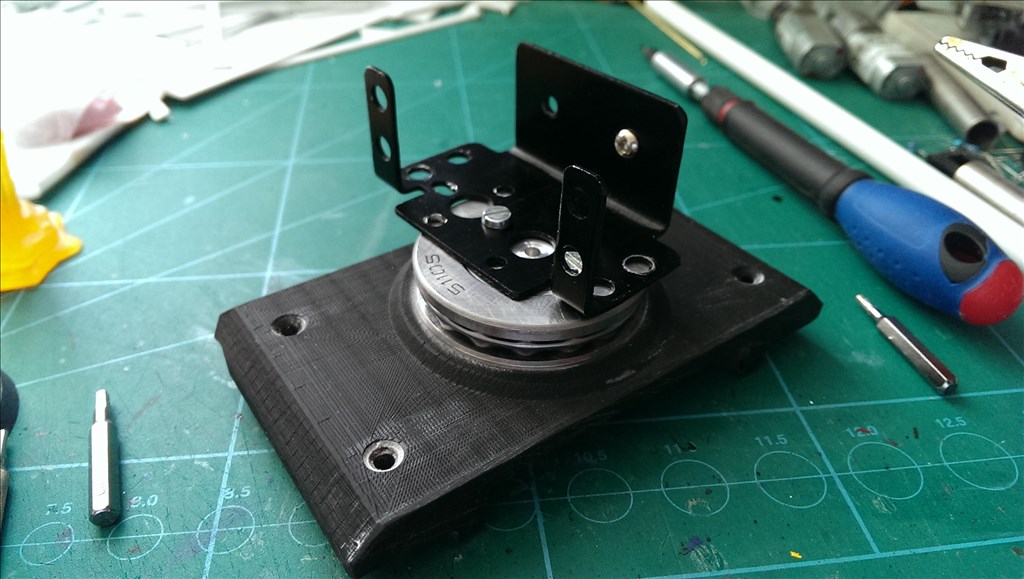
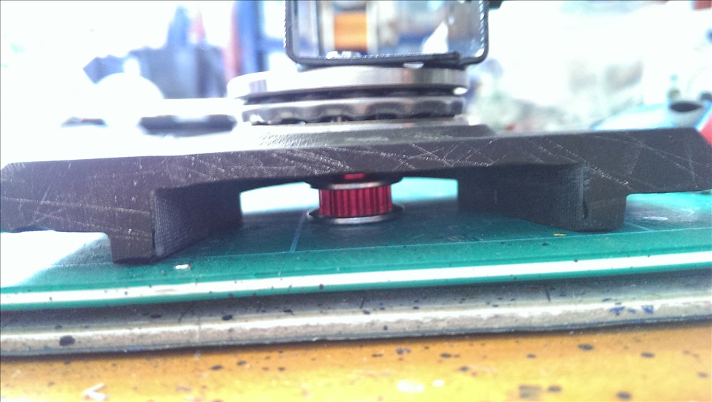
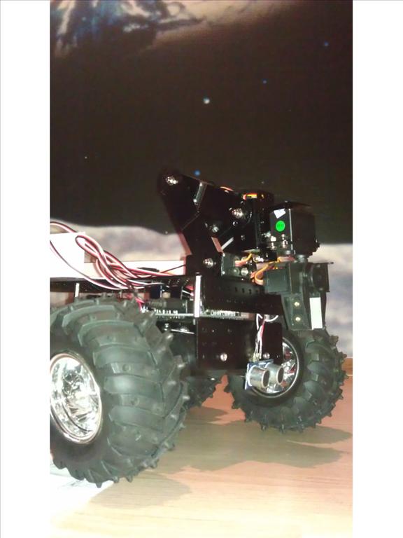
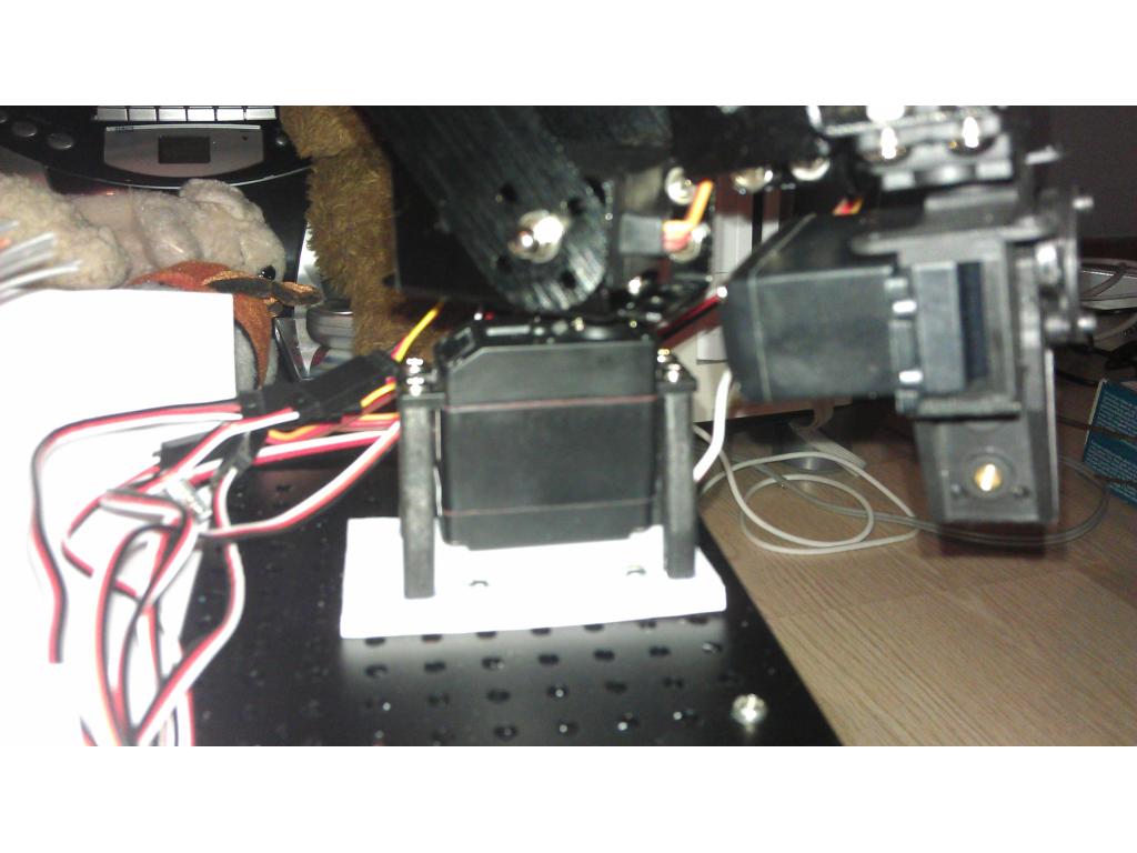
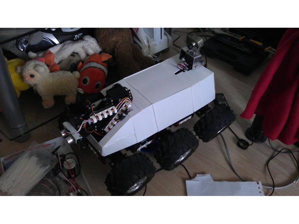
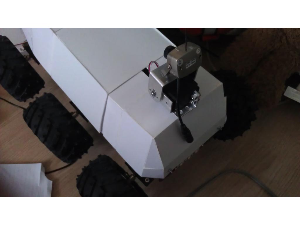
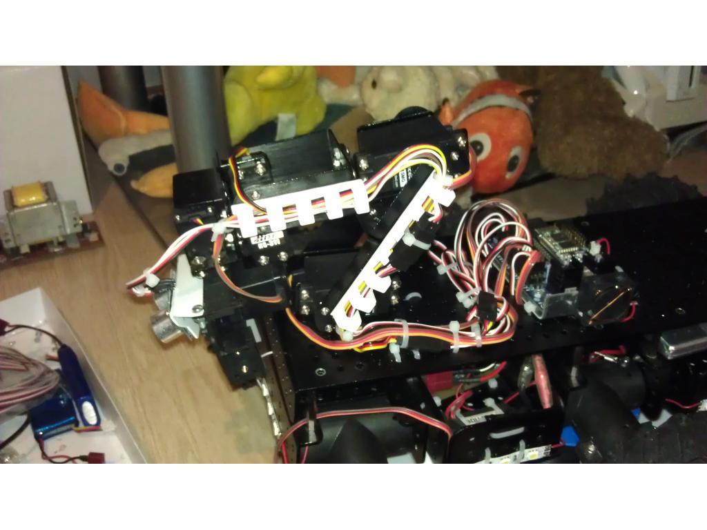
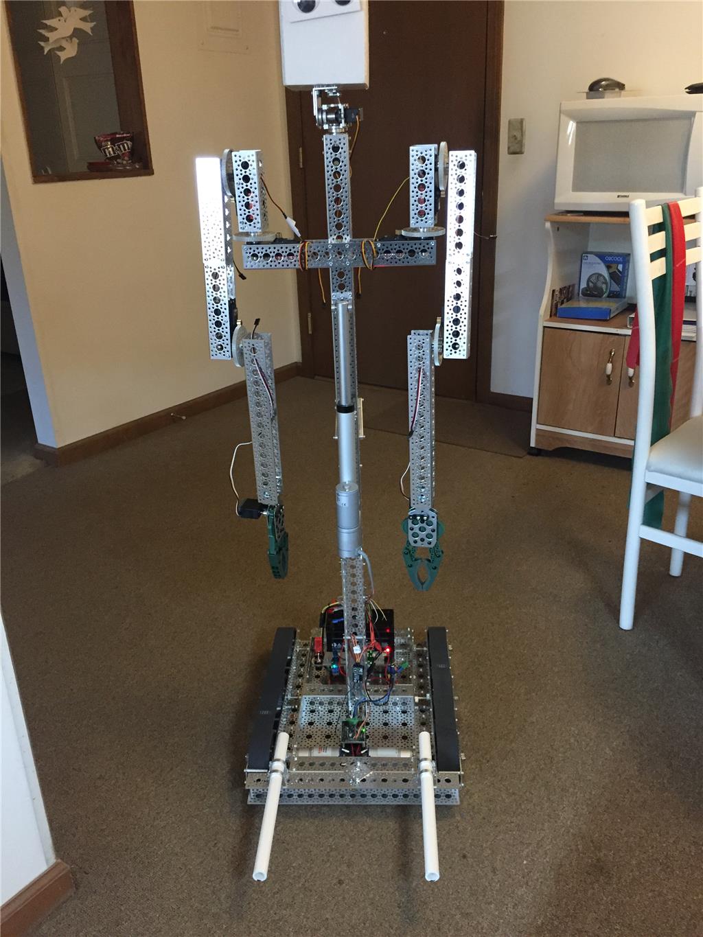
Latest update: I finally finished my robotarm. It now has 6 DOF! Under the existing arm I mounted a servo. It's a simple design, which I might change in the future to lower the height of the arm. I was planning to use a servo that could do 360 degrees, but I probably mixed something up and accidentally bought a modified servo... But It's oke... To fix this problem I'll mount in 1 or 2 microswitches to define a starting position.
Here some photos: