
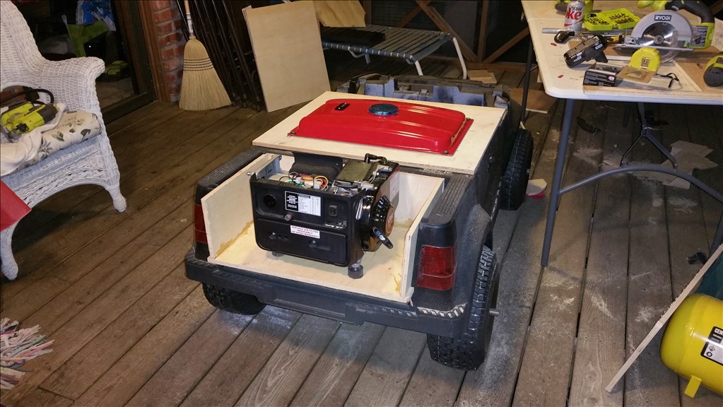
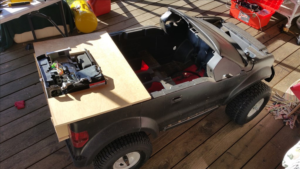

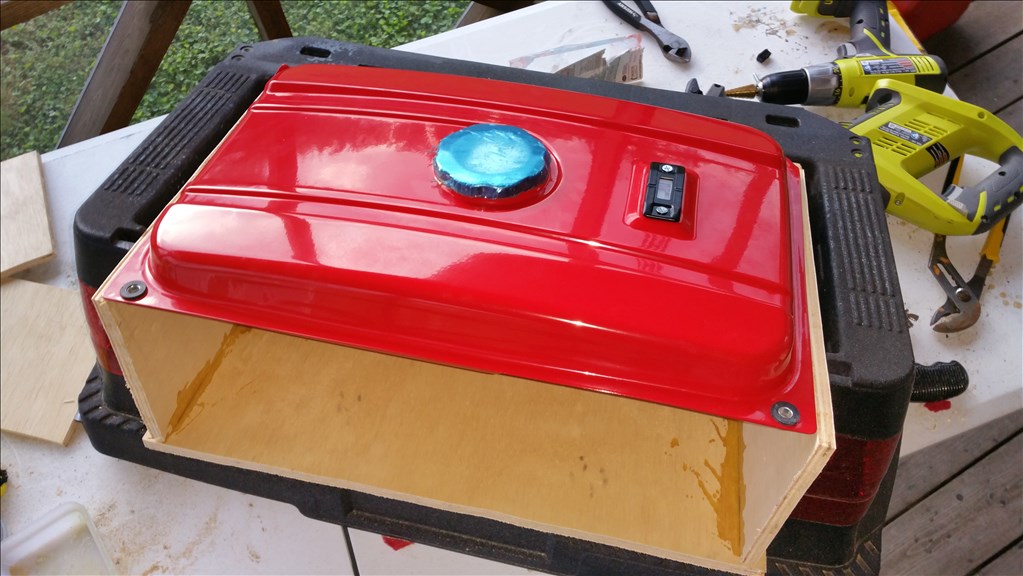
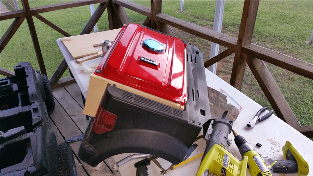

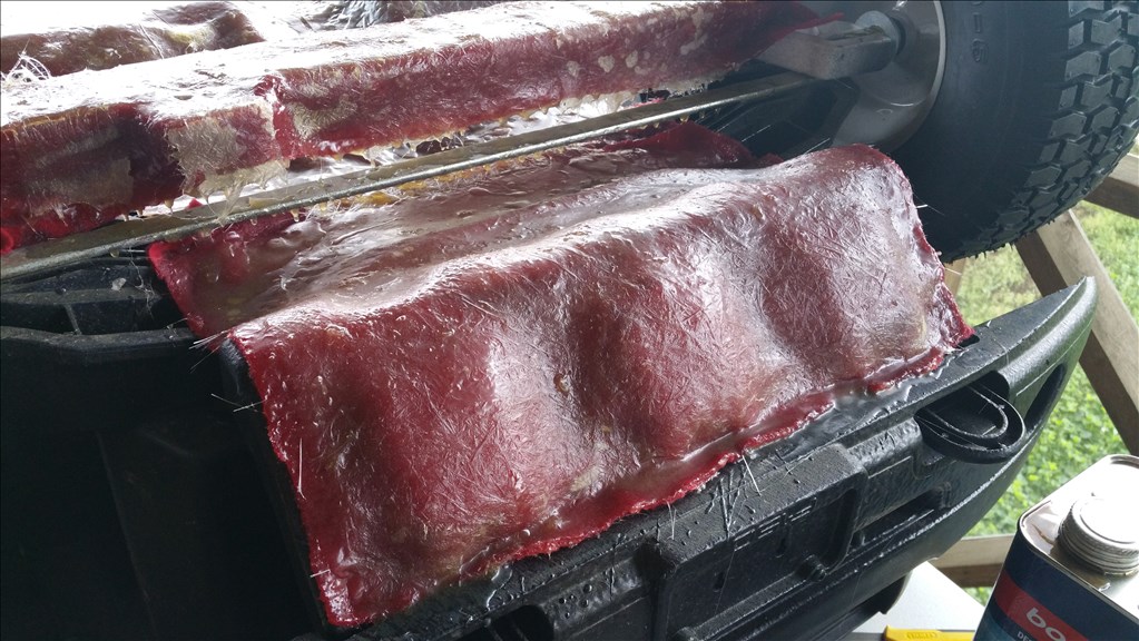
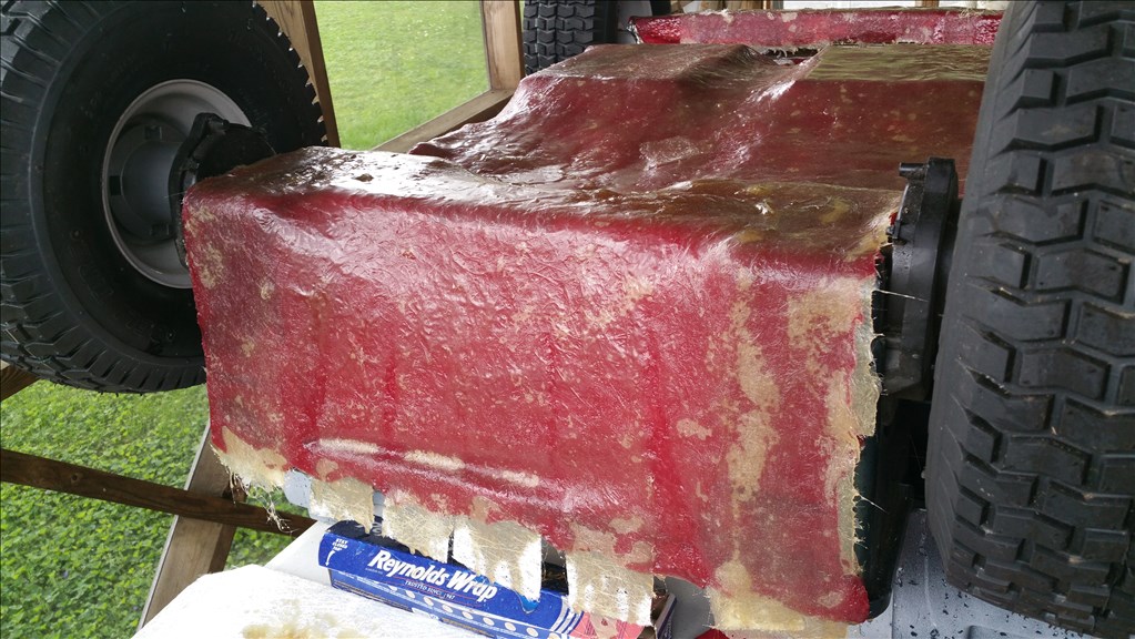
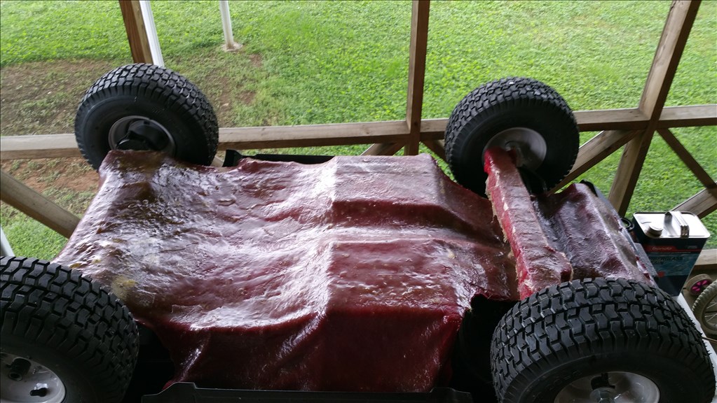

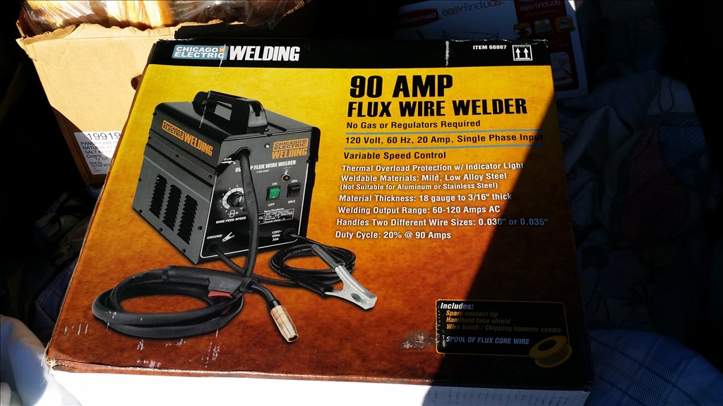

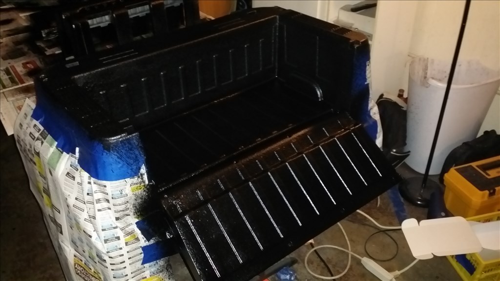
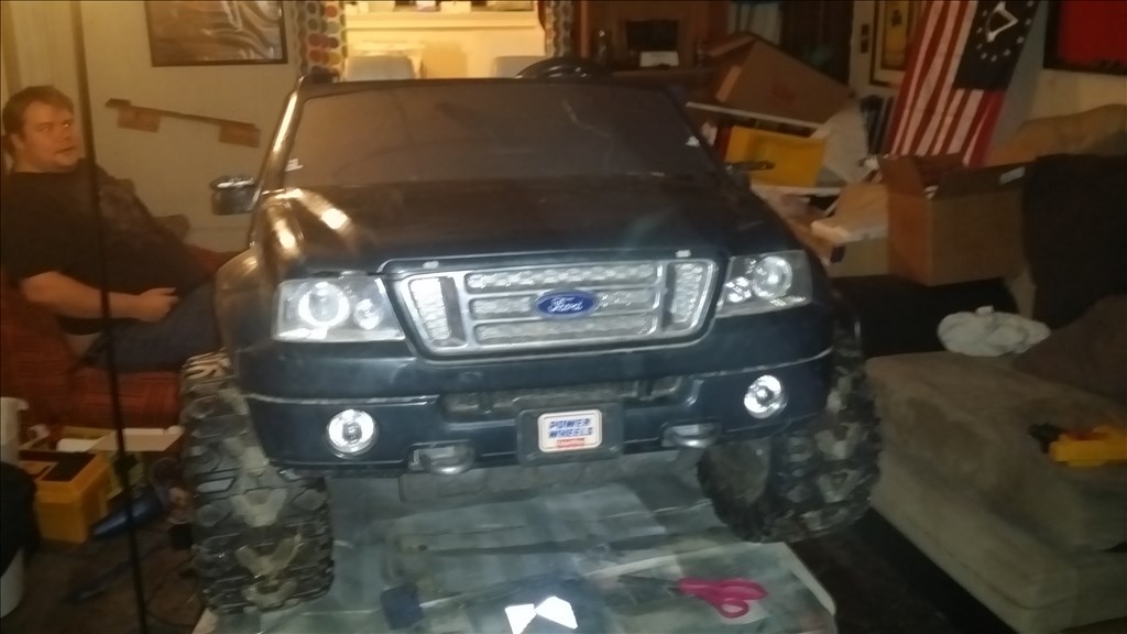
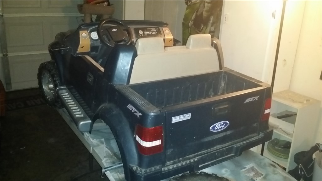

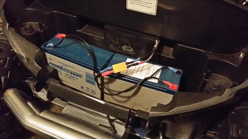
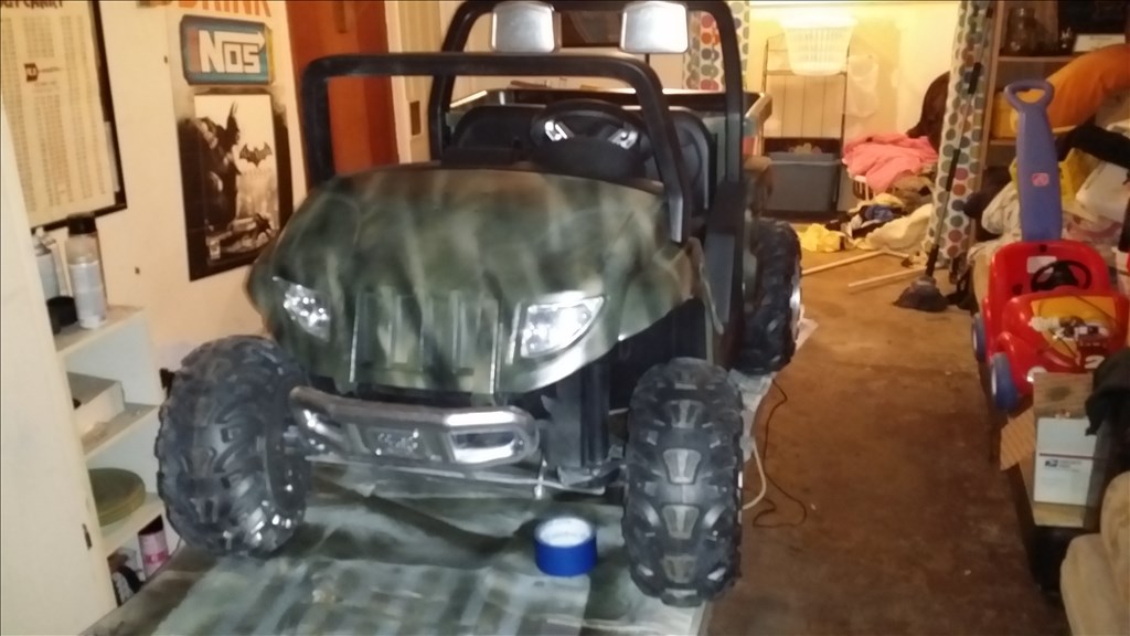
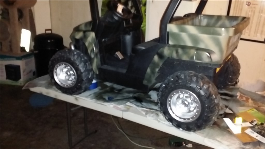
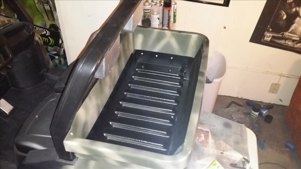
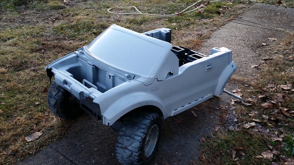
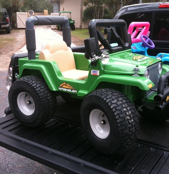
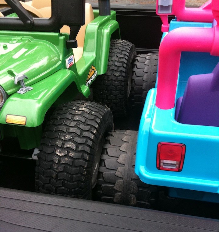


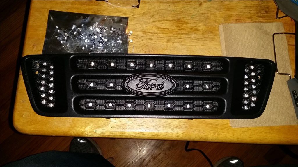
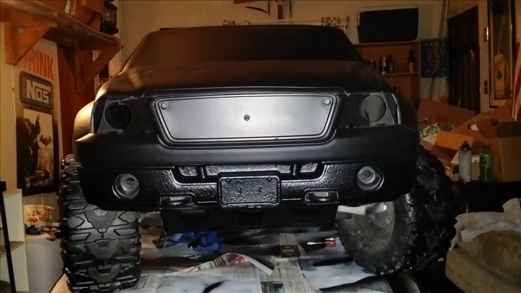
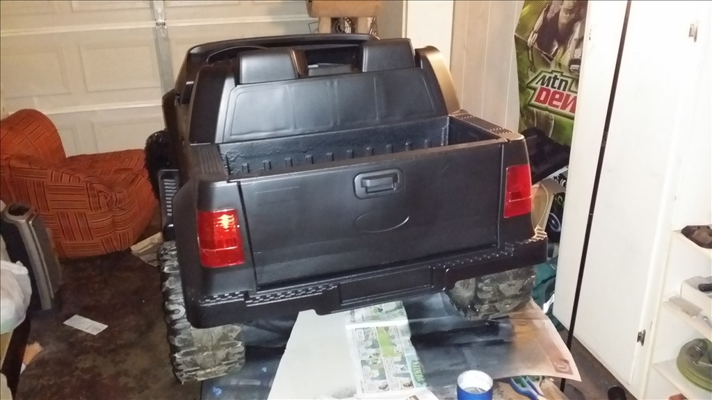
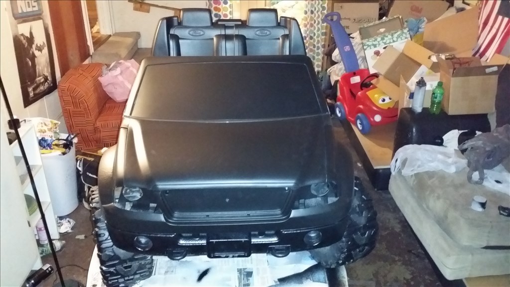


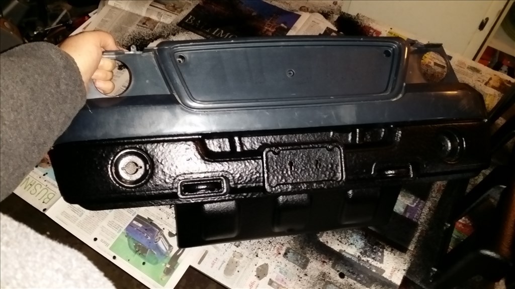
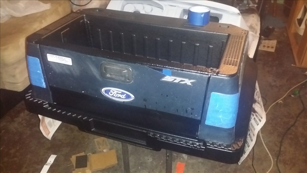
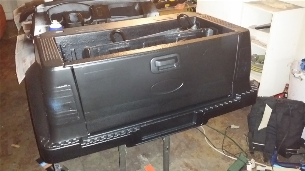
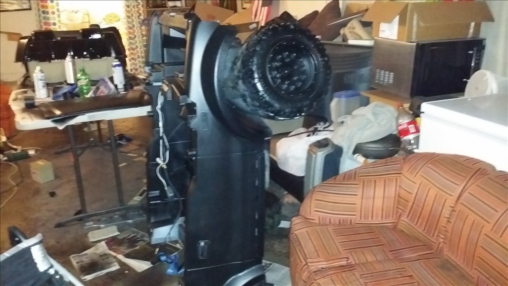
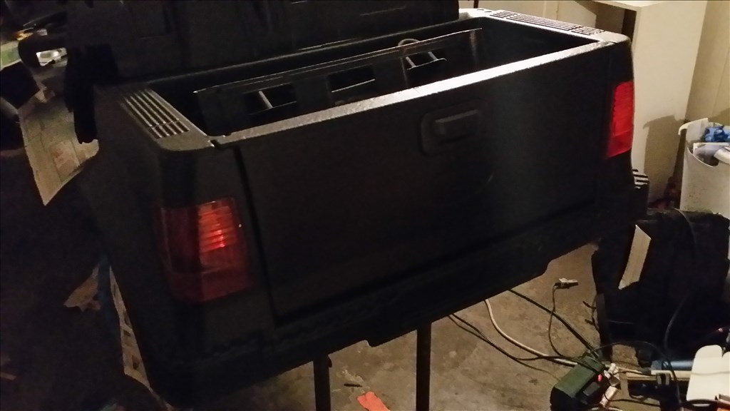


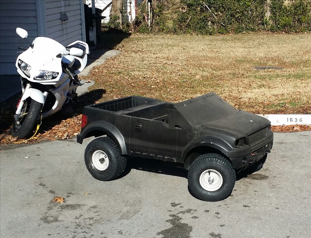
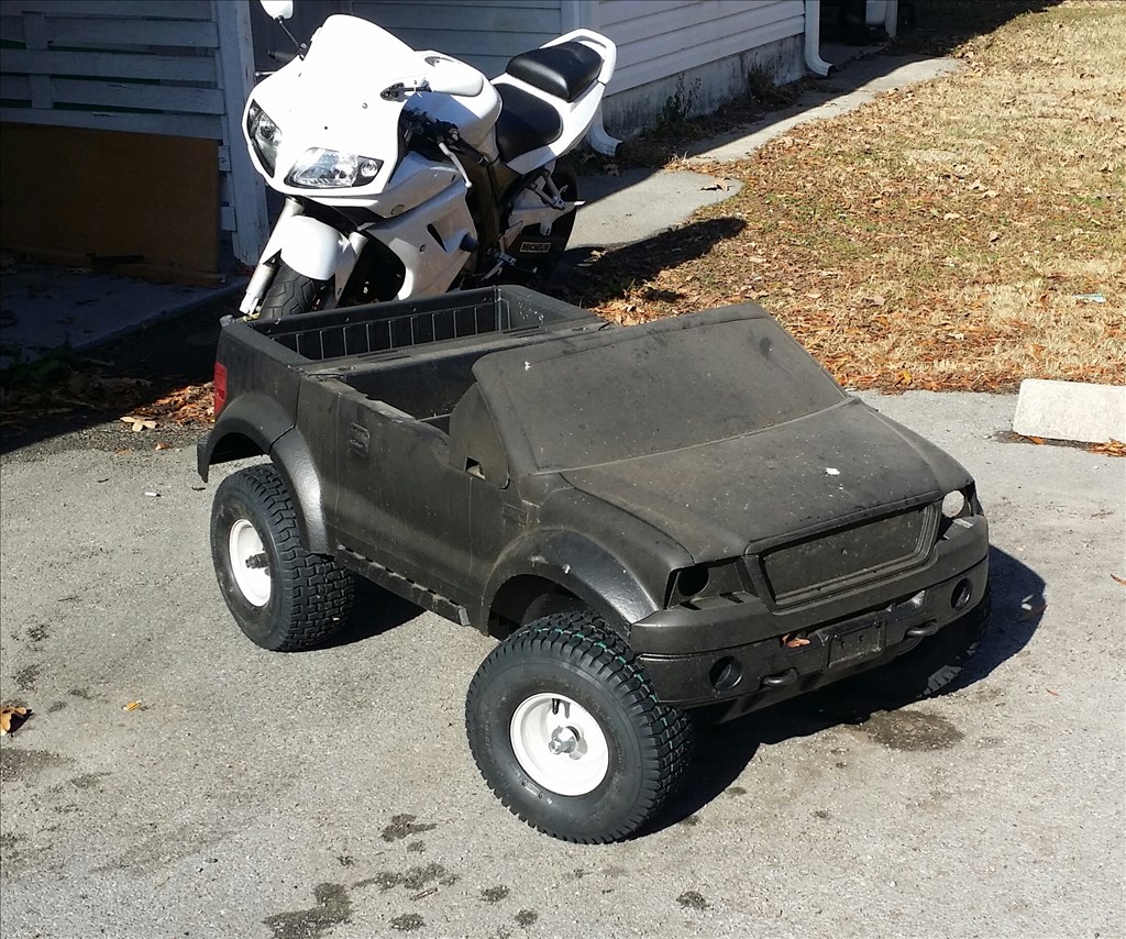
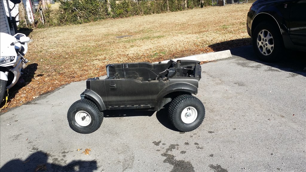
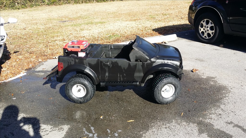
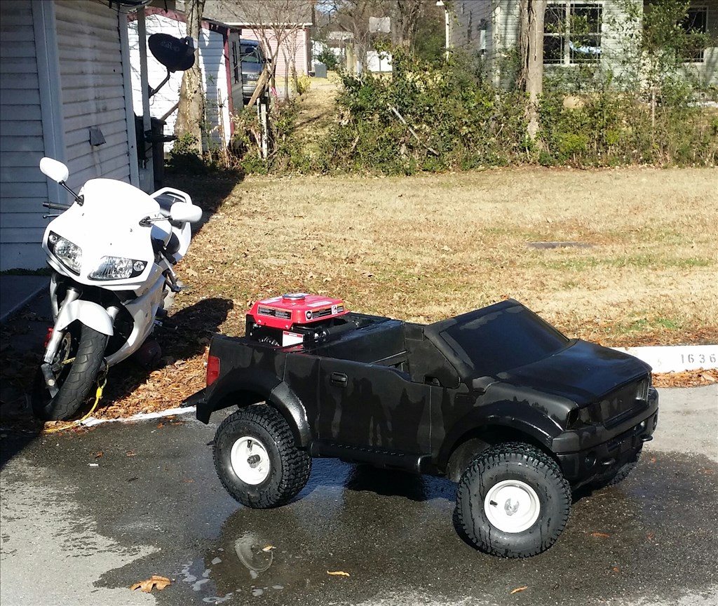
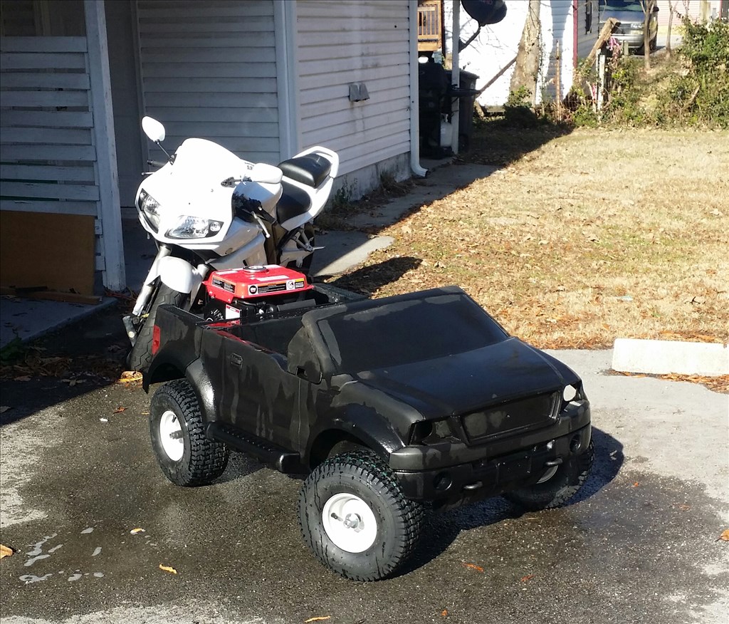
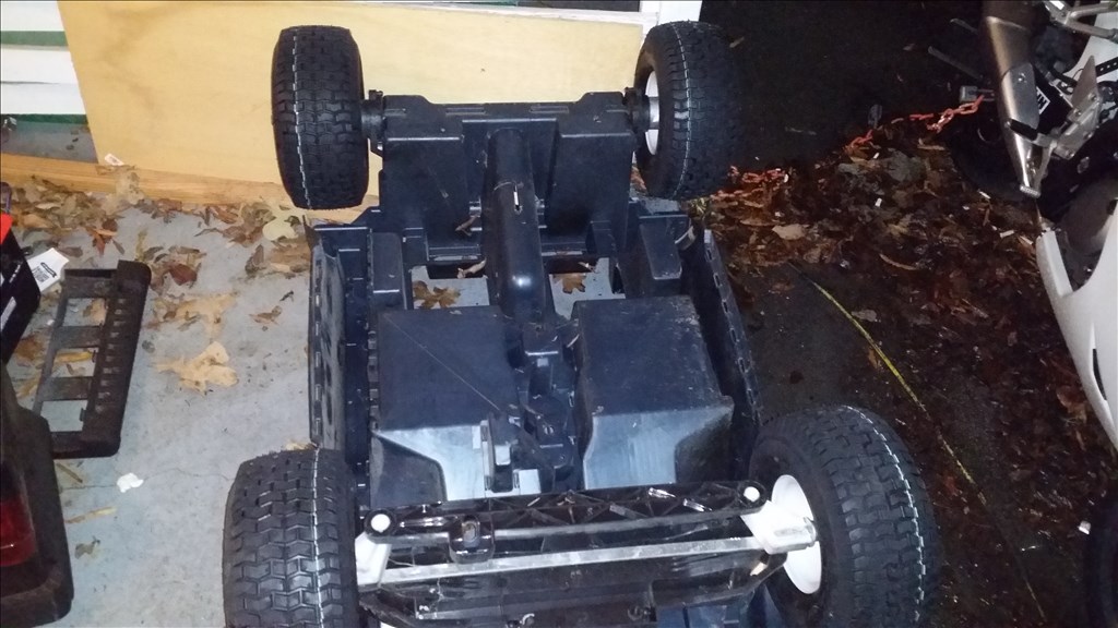
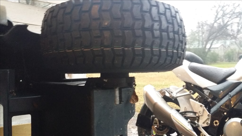

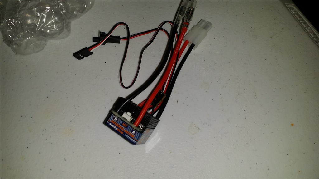


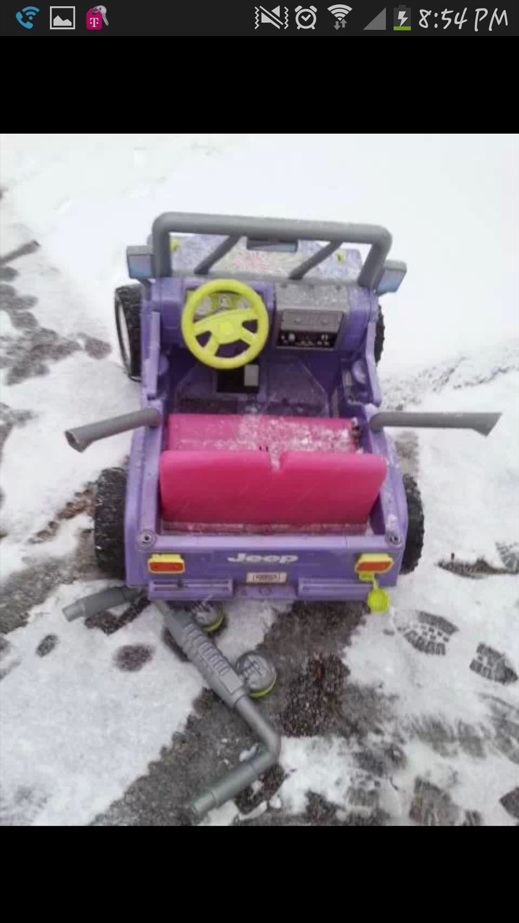
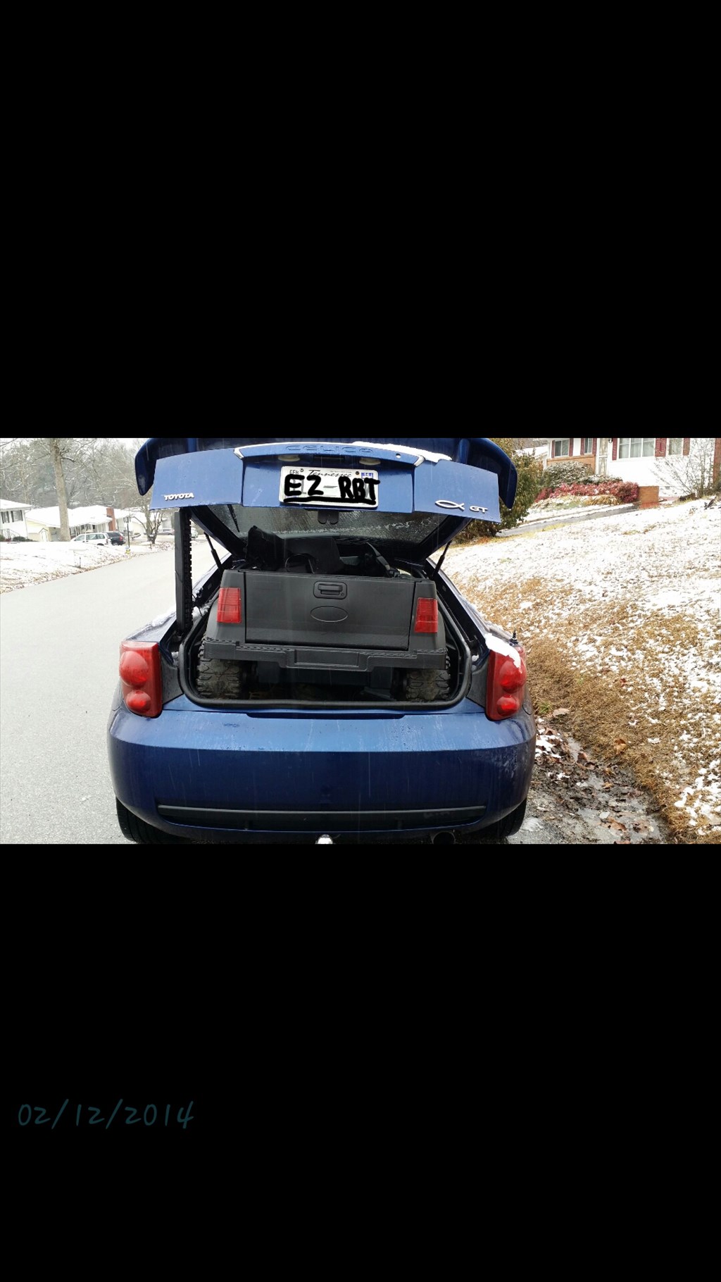
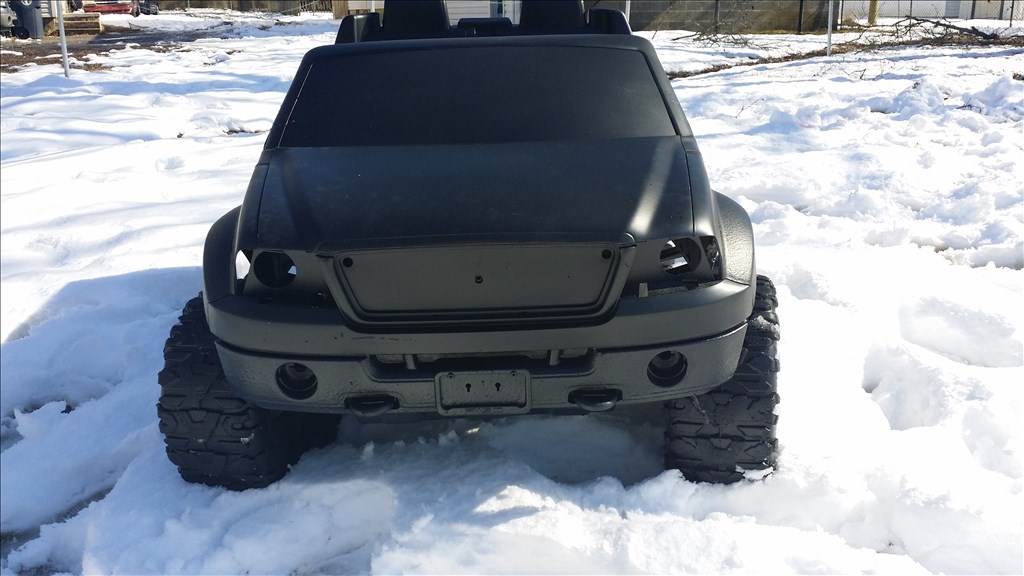
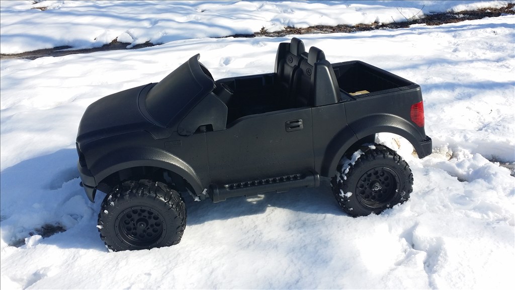

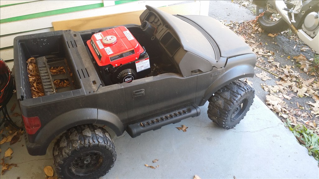

Hey Community , i really don't do enough fun projects. As you may notice many of my projects have a utility function. Squeegee mops, jarvis vacuums, smart marine fish tank is... well smart lol. So this is just for fun and I hope others enjoy it. I have already contemplated using it as a demonstration tool to get kids interested in technology. . Dang it! This is just for fun , ok I'll try not to get to serious with this. My friend Marty was talking about being able to drive the power wheels around while his kid was in it around the neighborhood. Or if his kid was driving and got to far he's just a button click away from stopping it. We found a free power wheels that had seen some rough years and we gave it a complete makeover. It looks better than new, new Gel cells from power sonic , smart charging and more. I gave it a cool high grass stripe camo.pattern and gave it to his son for his birthday. I'll post a couple pics. He's on the fence about doing the further mods so i searched craigslist.org for another power wheels that had been loved a little too hard. Searching for something with space and power I wanted I set my heart on a f150 , Toyota 4x or jeep 4x4. I didn't find a 4x4 model but f150 was the next best as it had dual gearboxes with rs585 motors. Also a good gel battery and charger was included. Here come some pics...
Discover more robots
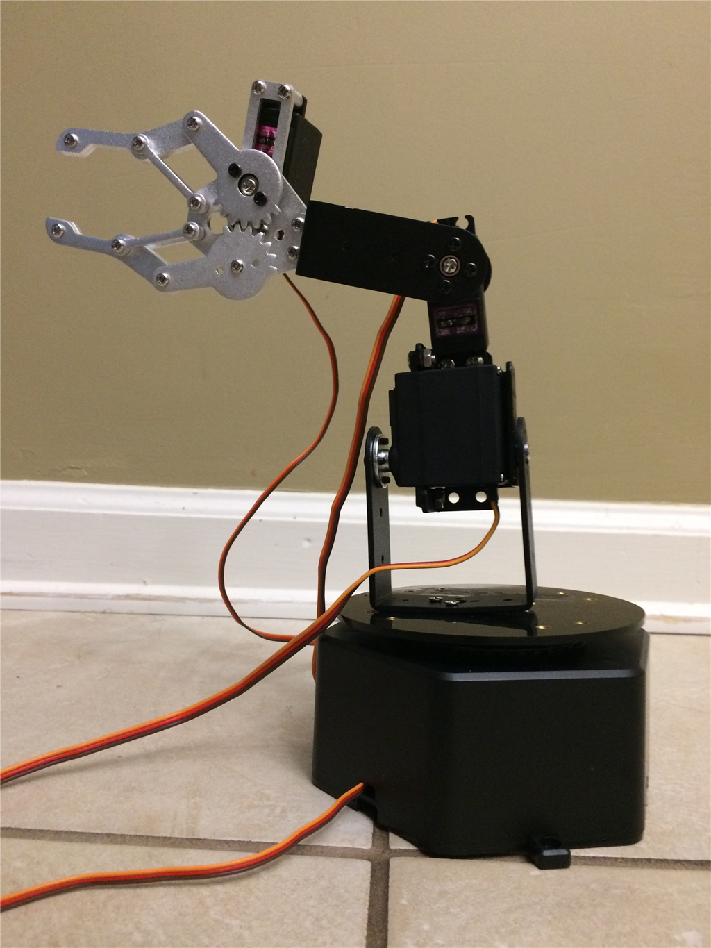
Ezang's My New Robot Arm On ARC
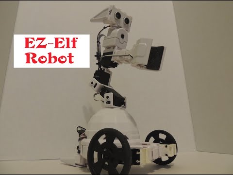
Justinratliff's EZ-Elf Robot


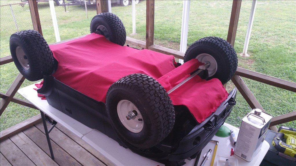
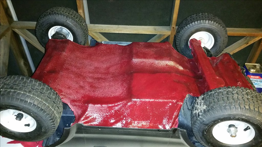
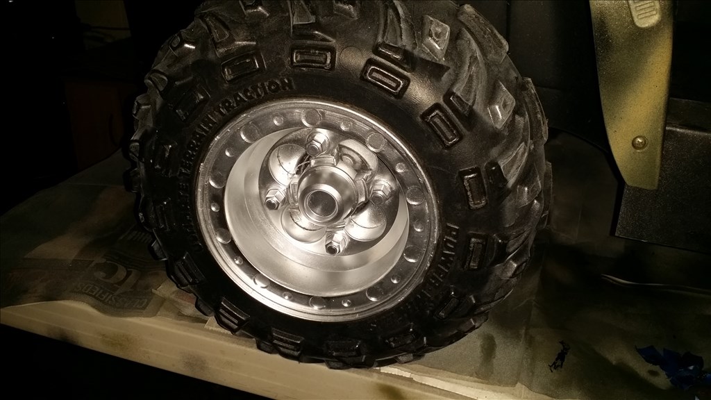
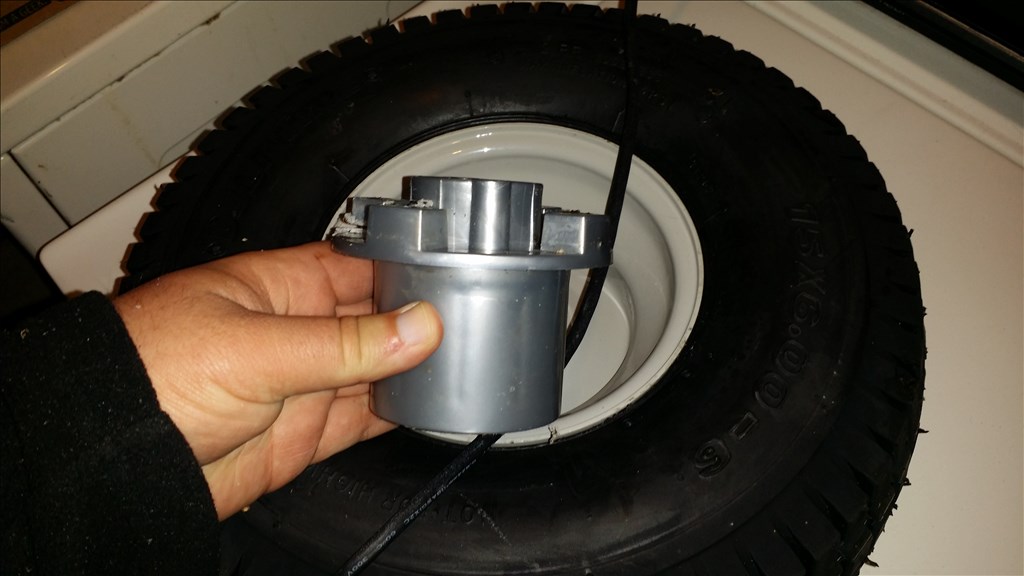
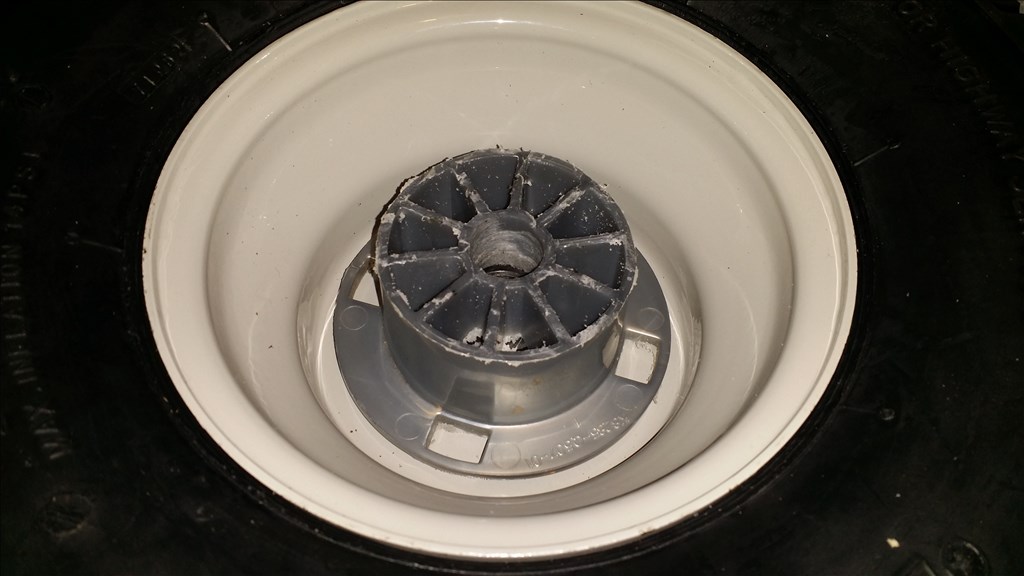
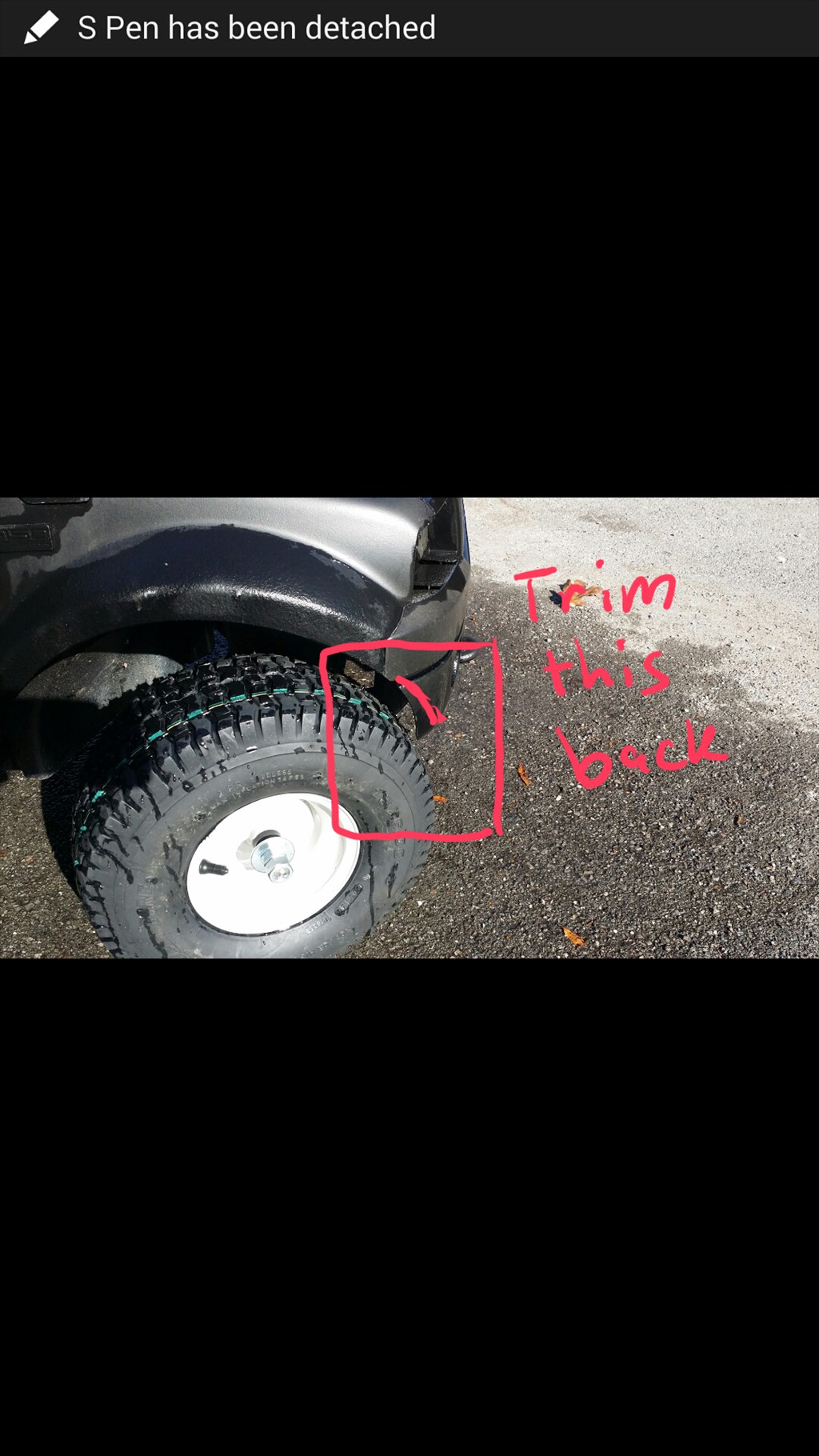
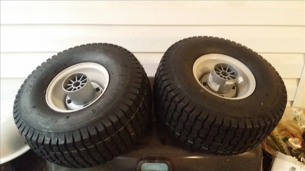
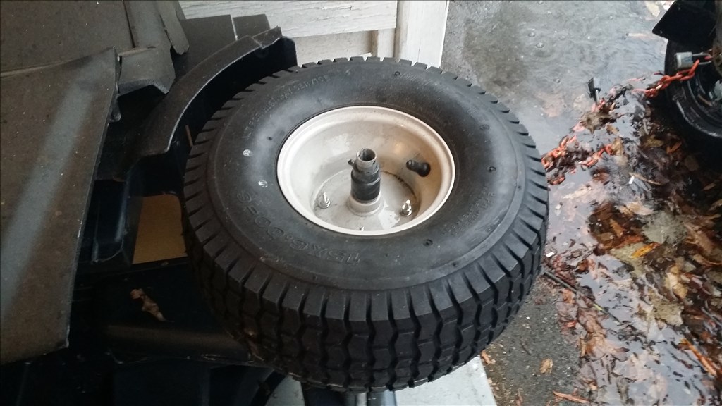
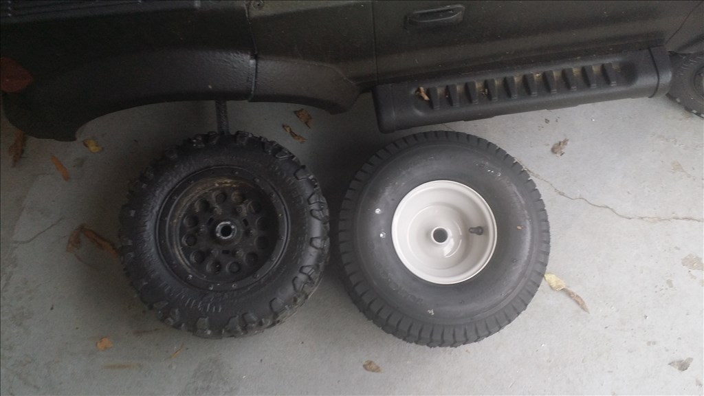
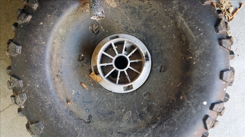
Ok so I have been cutting on the "drive hub that was screwed to the original hard plastic wheels. I made progress to get the hub to fit against the wheel but also accidentally cut too much off the end and now the tire rubs... oops. Well that sucks. I have two options. Either find a replacement online and redo the cut or try drawing this whole part on 123d design and 3d print it. 3D printed PLA is probably not near the strength of heat injected ABS plastic. Here are pics..
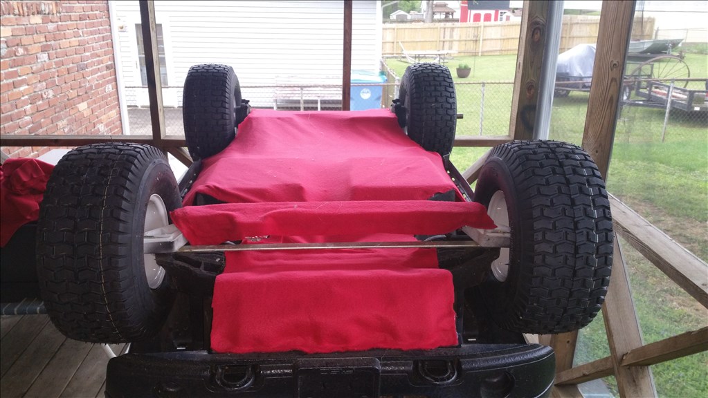
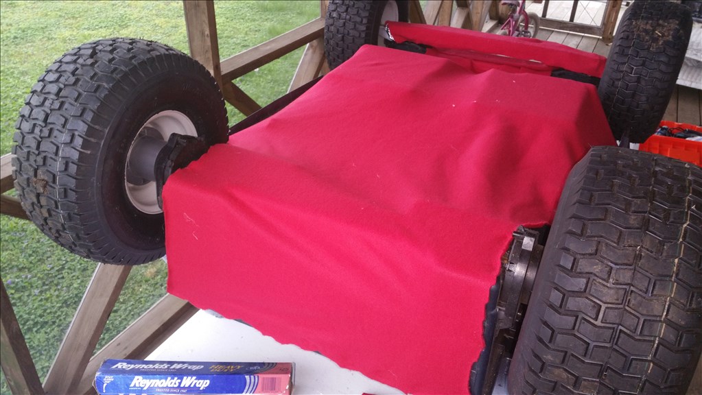
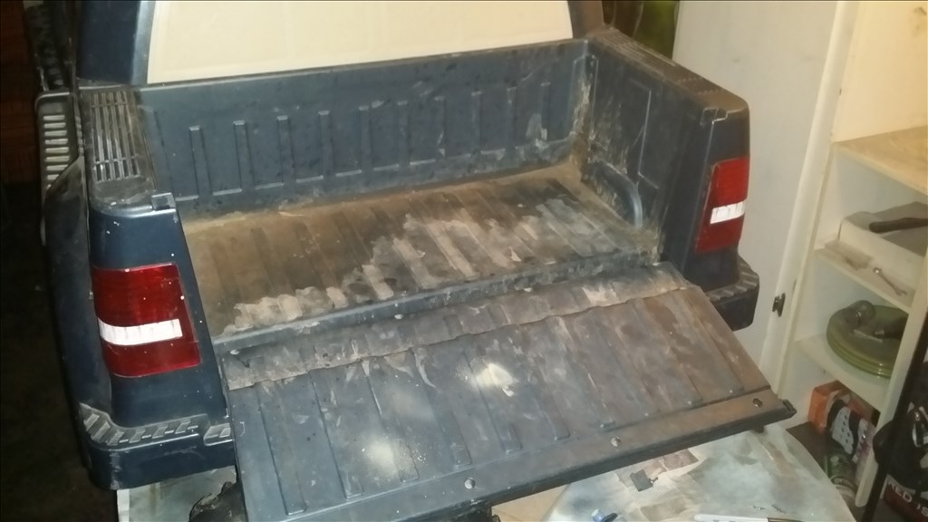
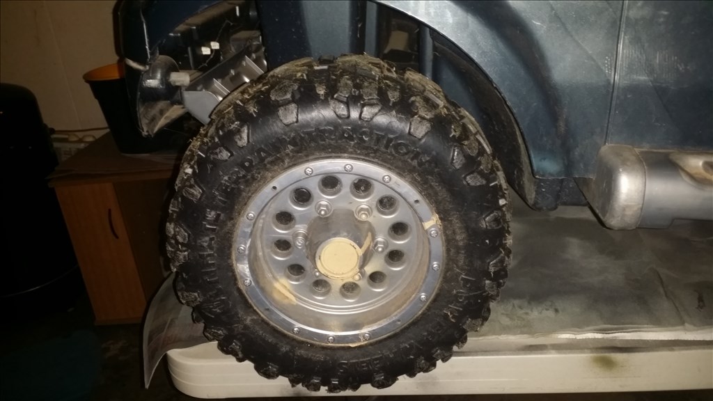
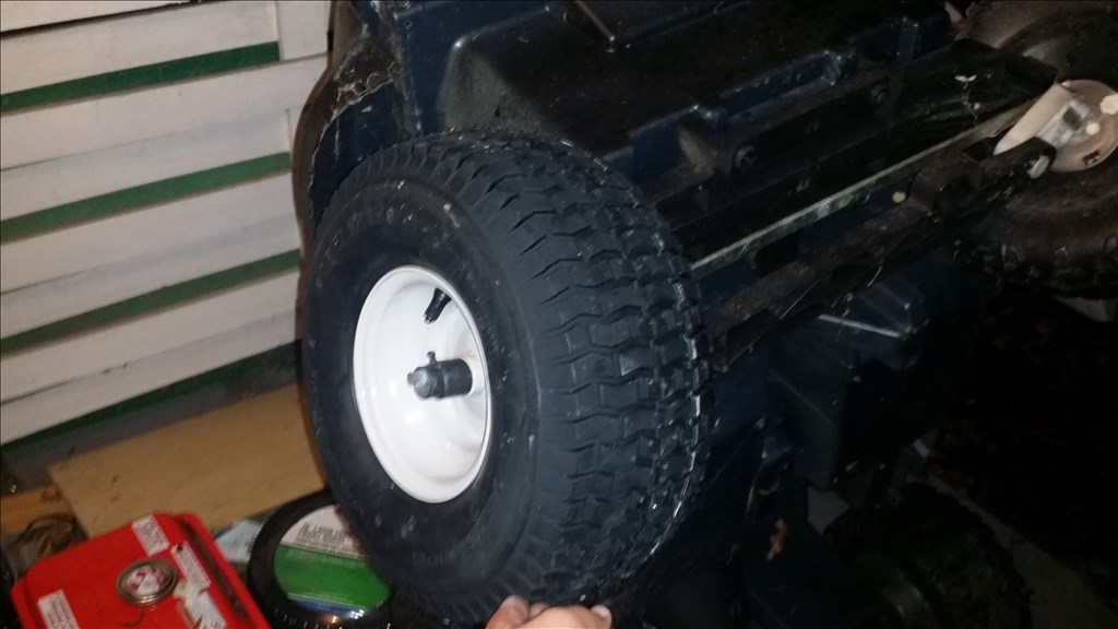
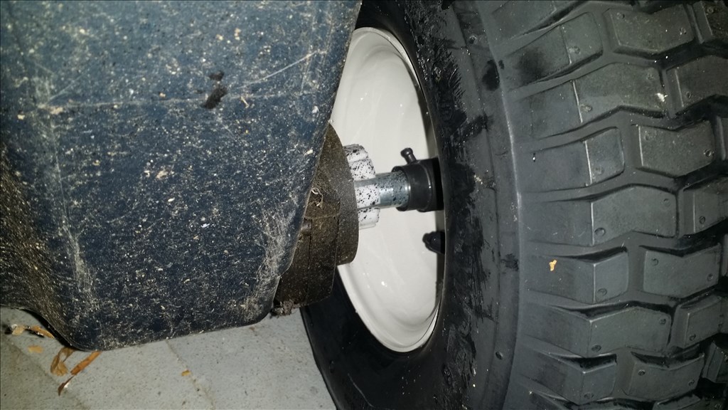
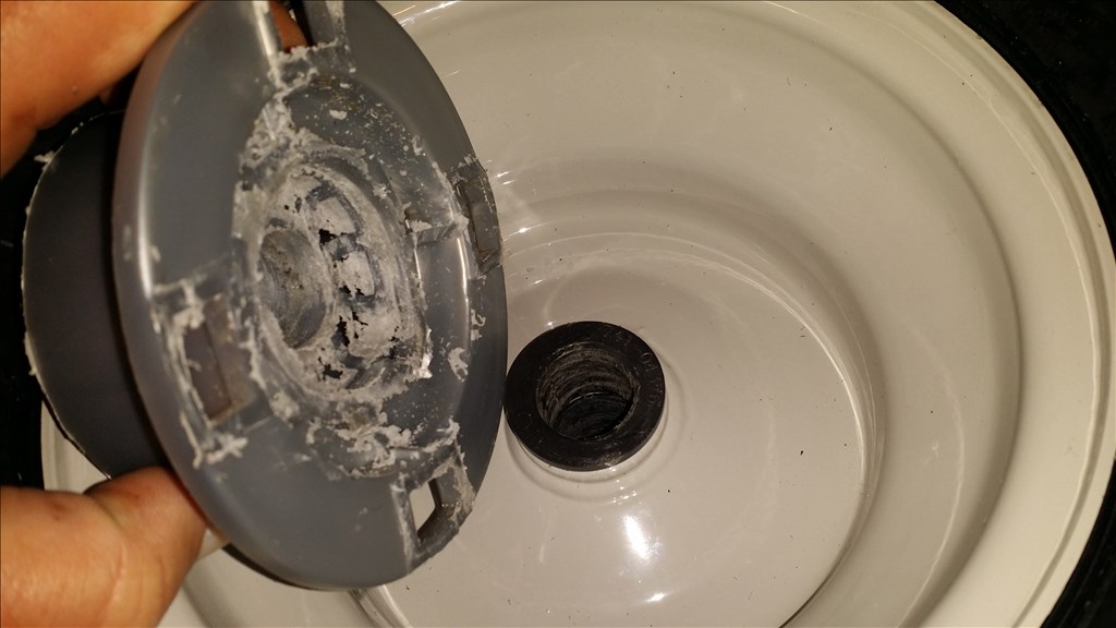
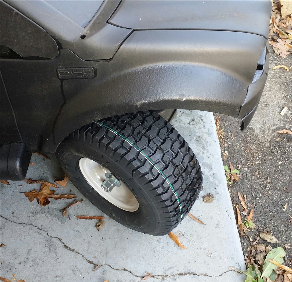
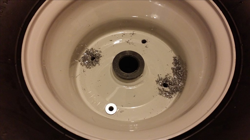
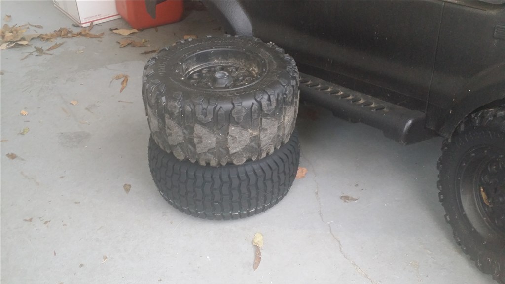
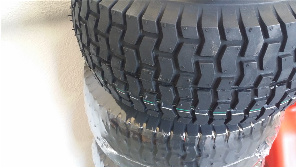
Here is the tire in ideal position and you see the gap that I must fit the drive hub into.

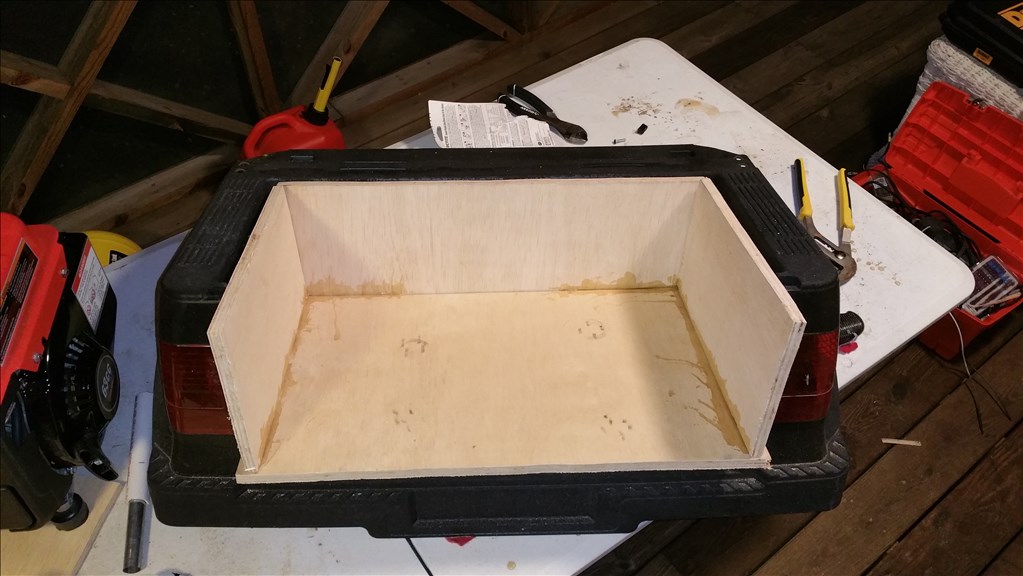
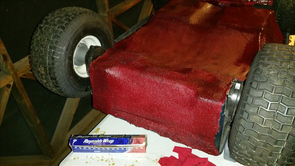
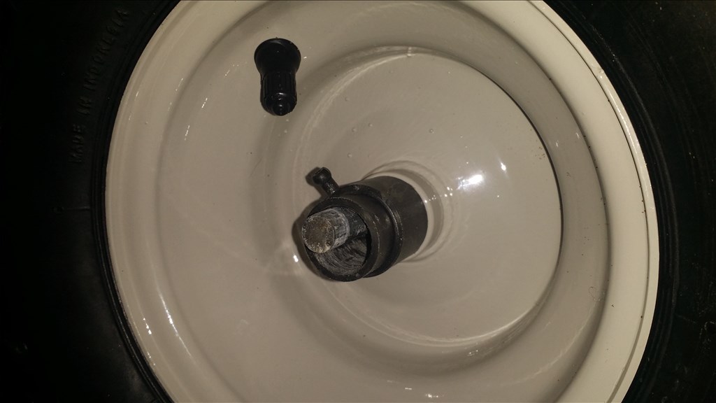
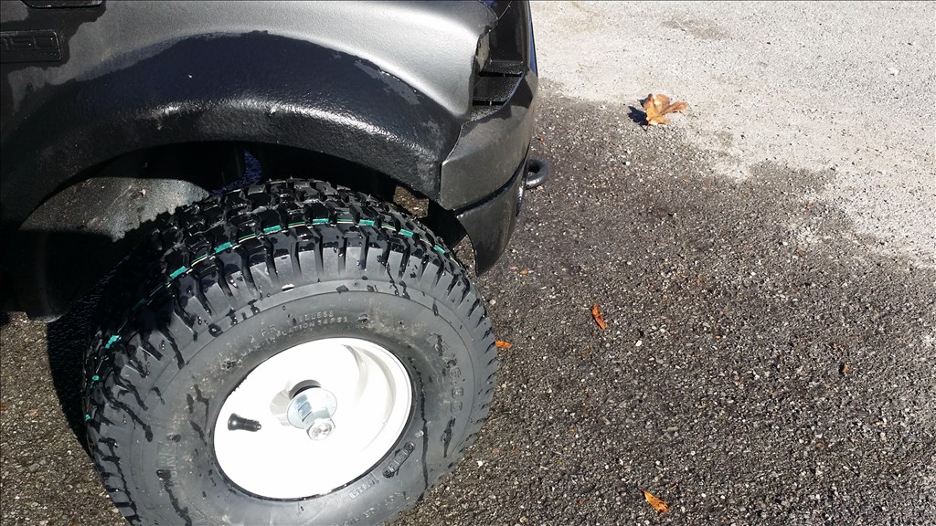
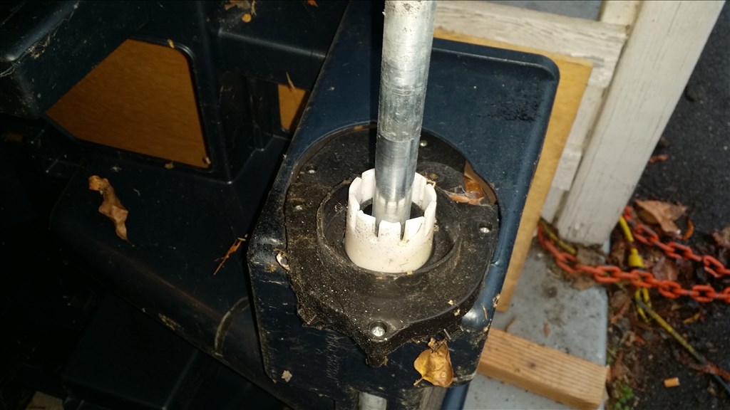
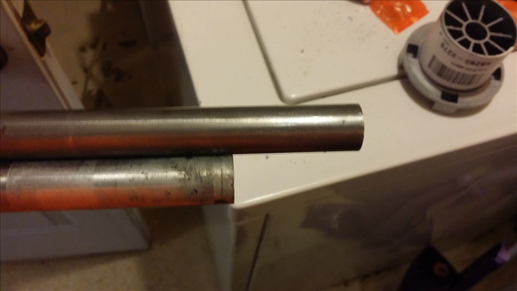
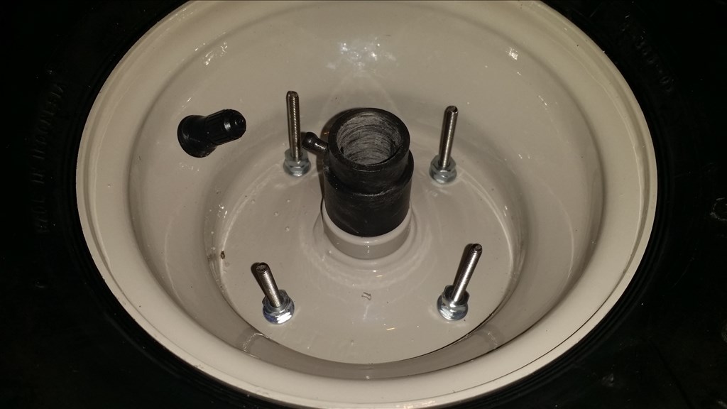
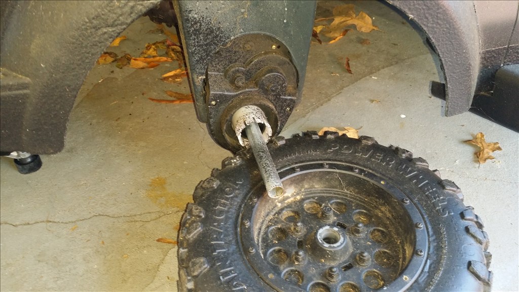
This top part is where I screwed up. I should have left that alone. What happened was the axle slid towards the other tire so when I did the test fit I thought I needed to trim another half inch.Ok so I have been working to see what I can do to get the front tires on. The front axles are about half of the size. I have two options.
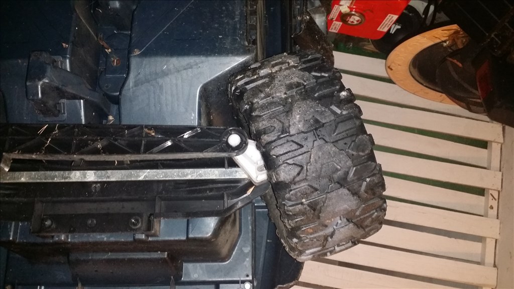
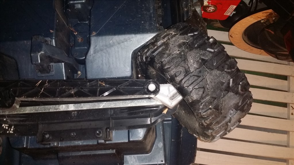
The steering is limited by stopper nubs of both sides of the steering link. I cut these out to see what kind of additional range I would get without them.

Before the range of steering change.
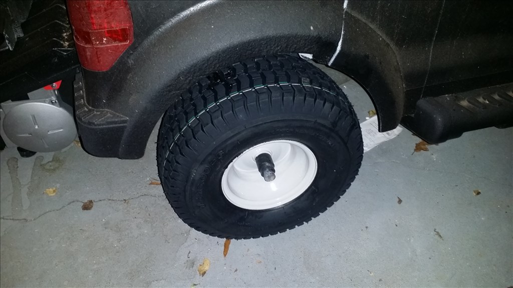
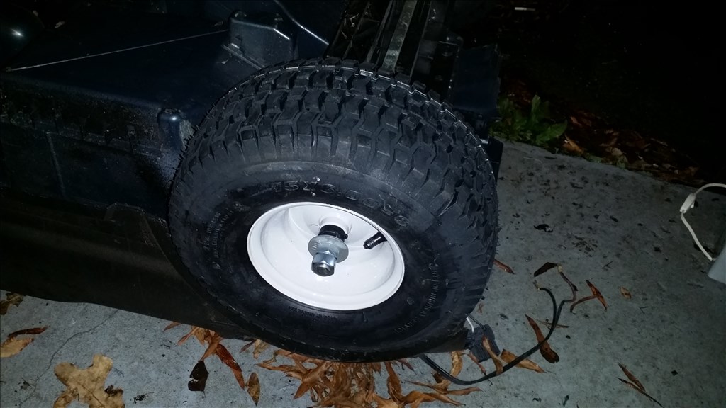
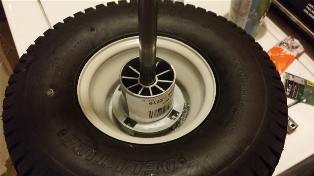
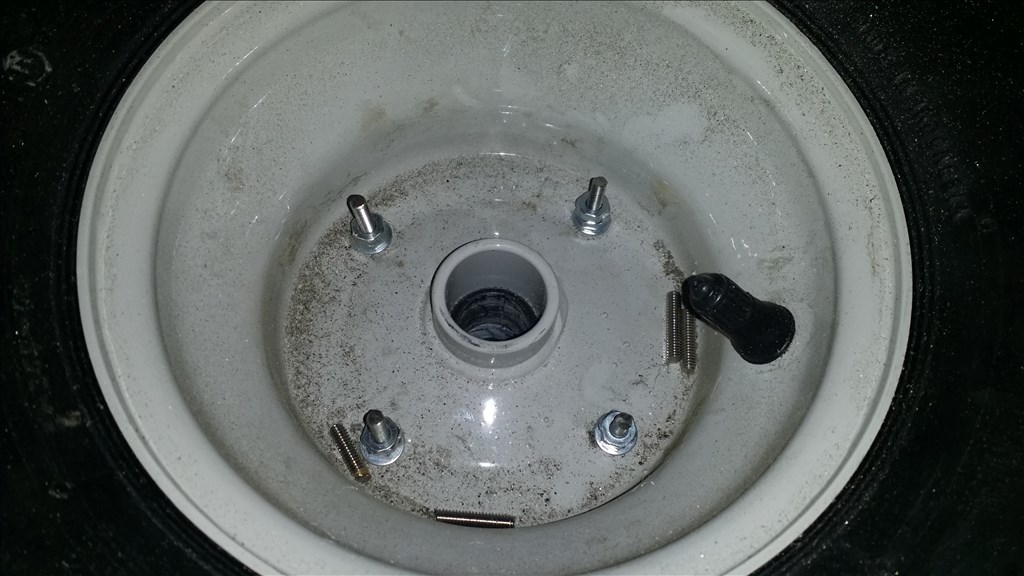
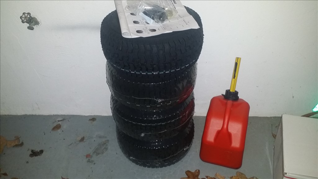
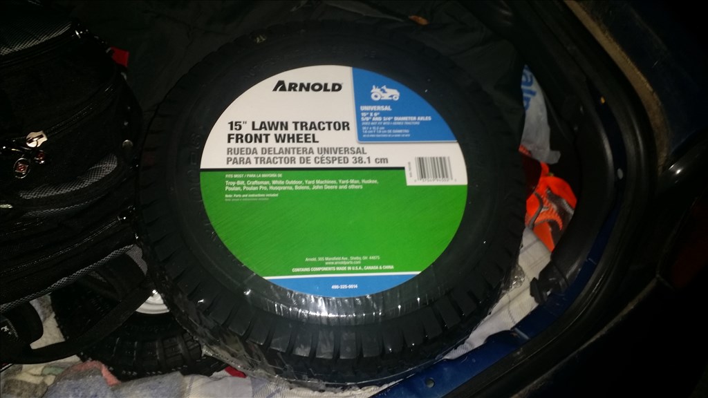
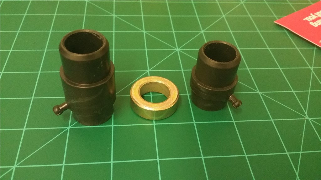
Here is the additional turning range without rubbing after the nubs are removed.Ok so as previously noted I cut the hub about a inch too short because the shaft slid. I found cheap replacement hubs for less than 4 dollars each and that negates the time it would take to model them in 3d and print on the Makerbot as I would need to print with zero infill for strength.
I purchased 4 total just in case they are needed for some reason. The price was too cheap not to.
Nice recovery!
Ok so I really want this project mobile within a couple weeks before colder weather with Ice and snow arrives. It doesn't need to be finished , but I still want it moving. I looked at other steering arrangements which varied from windshield wiper motors to 300 dollar 100 pound linear actuators. In either case I opted for a cheaper option that also allows me to upgrade later to a stronger servo or add an additional gearbox in tandem which is common in RC Monster trucks for off road / rock crawling.
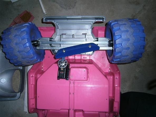
Here is one "ok" diy install of the servo gearbox and a typical 10kg servo on a barbie jeep.
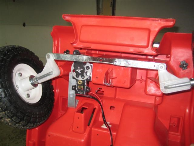
And another example
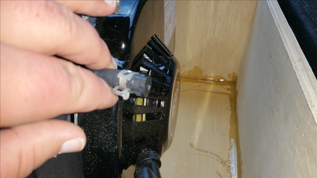
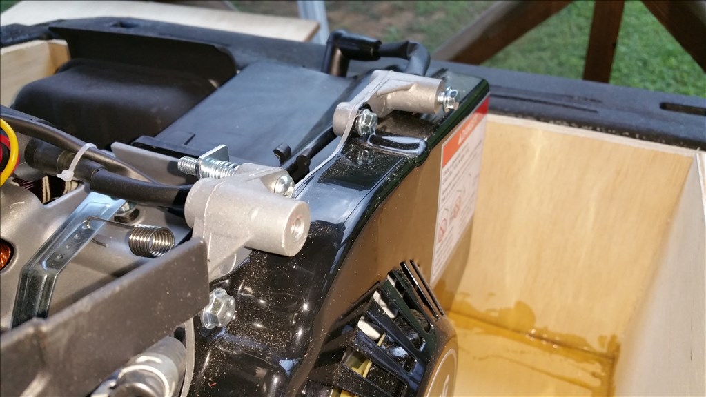
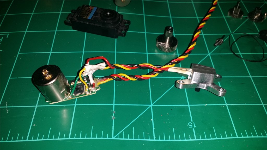
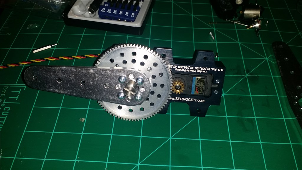
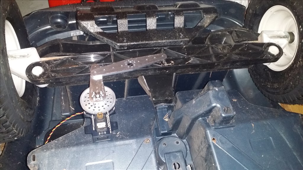
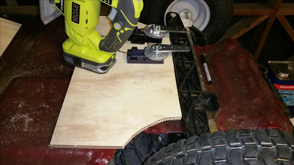
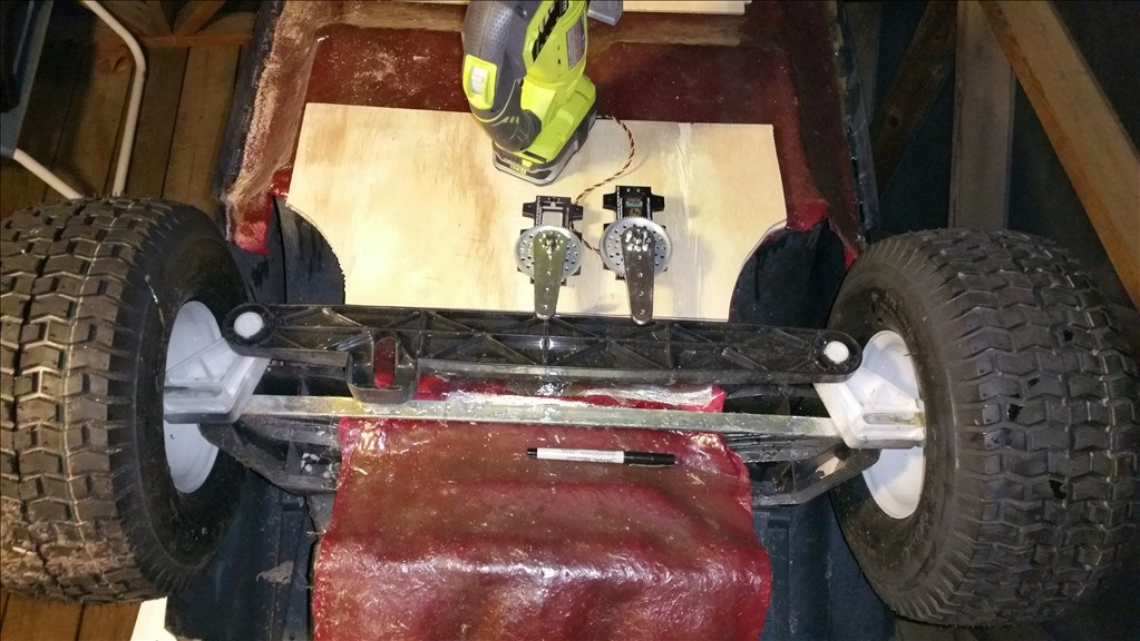
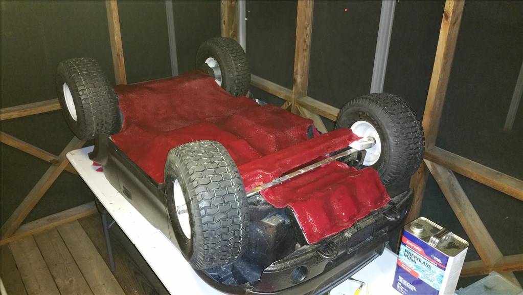
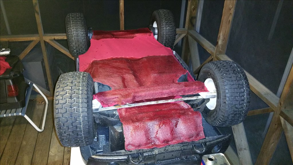
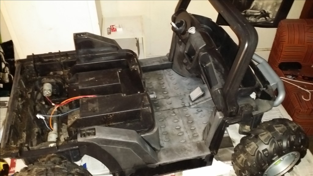
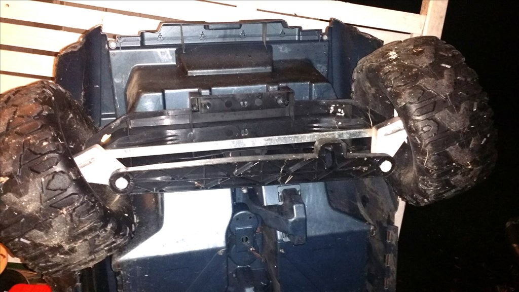
Here is my current power wheels f150 steering system. The metal bar is just for stability, but the large back bar is the "moving" part.
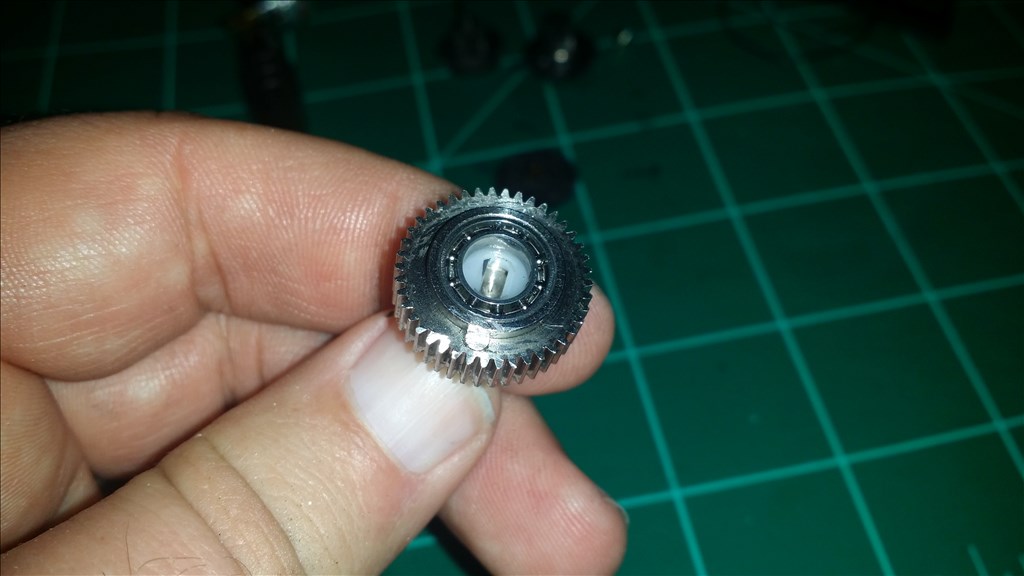
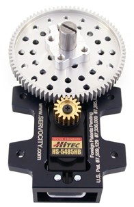
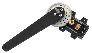
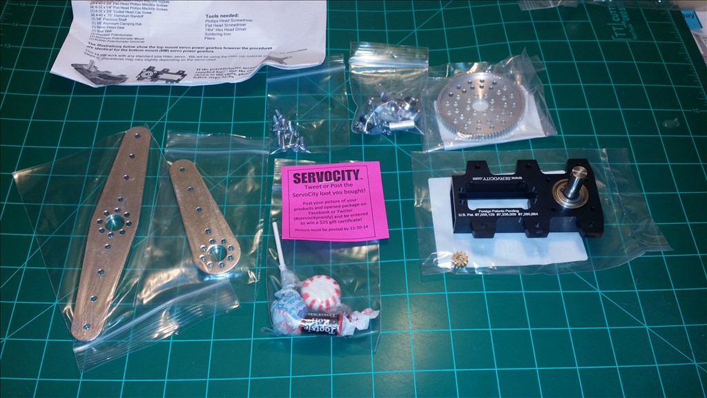
I have the servo city 400 servo gear box with surface mount tabs and a 7 to 1 gear ratio.
I have two servo options from what I have in my toolbox. Power HD 1501mg , 240 Oz. in. @ 6v
7 x 240= 1680 Oz in. /3 in servo horn =560 Oz in
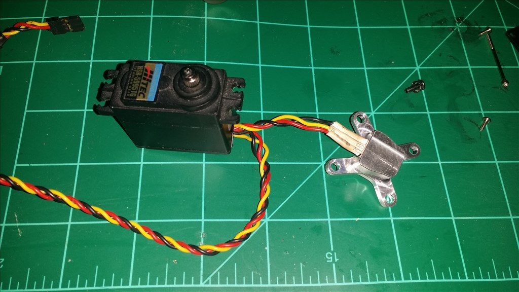
Hitec 5595tg 333 Oz. in. @ 6v
7 x 333 =2,331 Oz. in.
2331 /3 in servo horn= 777 Oz in
It is possible for the torque to be higher on higher voltage ( 7.4), but I also need to keep the servo cool.
A 7 to 1 gear ratio also slows servo response from .16 to 60 degree 7 times slower. So with the gearbox it would be 1.12 seconds per 60 degrees rotation. That's about 2.26 seconds from lock left to lock right. So I believe it will be usable. In the worse case scenario I would swap to a 5 to 1 ratio and tandem the connection for two servos to move together.