


I know I should finish Melvin before starting a new build but Josh's Jarvis has inspired me to give my JARVIS a physical form.
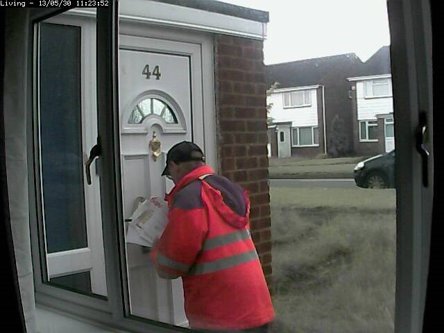
Some already are aware that I already have a JARVIS like system installed in my whole house which carries out a multitude of tasks from being an automatic PVR (like Tivo but better), controlling the heating and hot water system, controlling lights... too much to list really but one day I will attempt it.
Anyway, since it doesn't currently use ARC or an EZ-B I haven't posted much about it on here, but that's changing for 2 reasons...
- To inspire you guys to open a can of awesomeness and
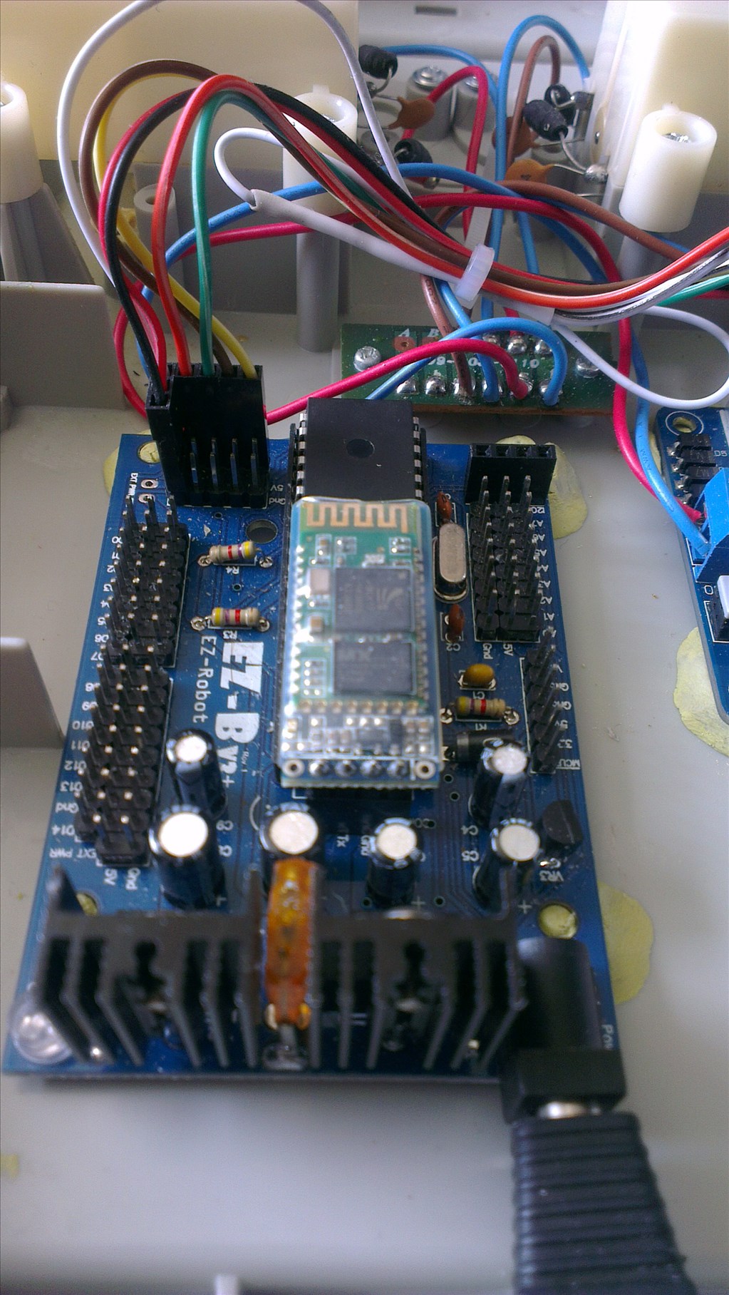
- Because finally JARVIS will become a real robot rocking an EZ-B.
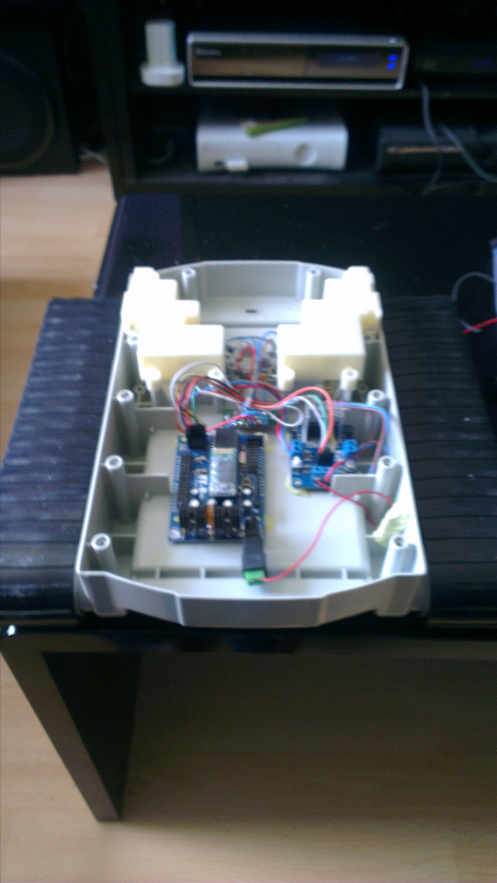
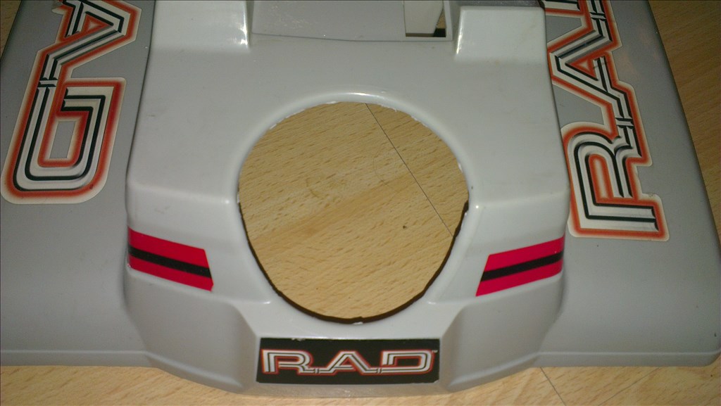
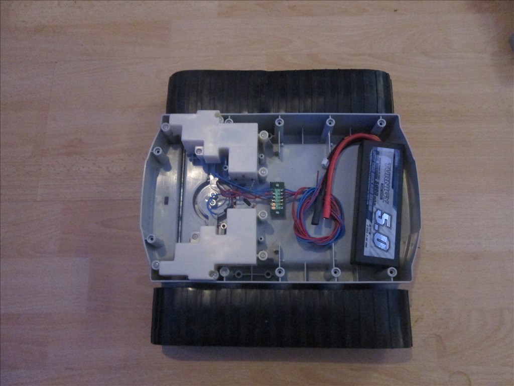
Basing the design around a RAD V1 robot
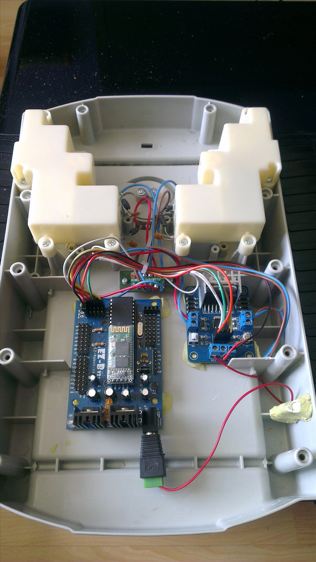
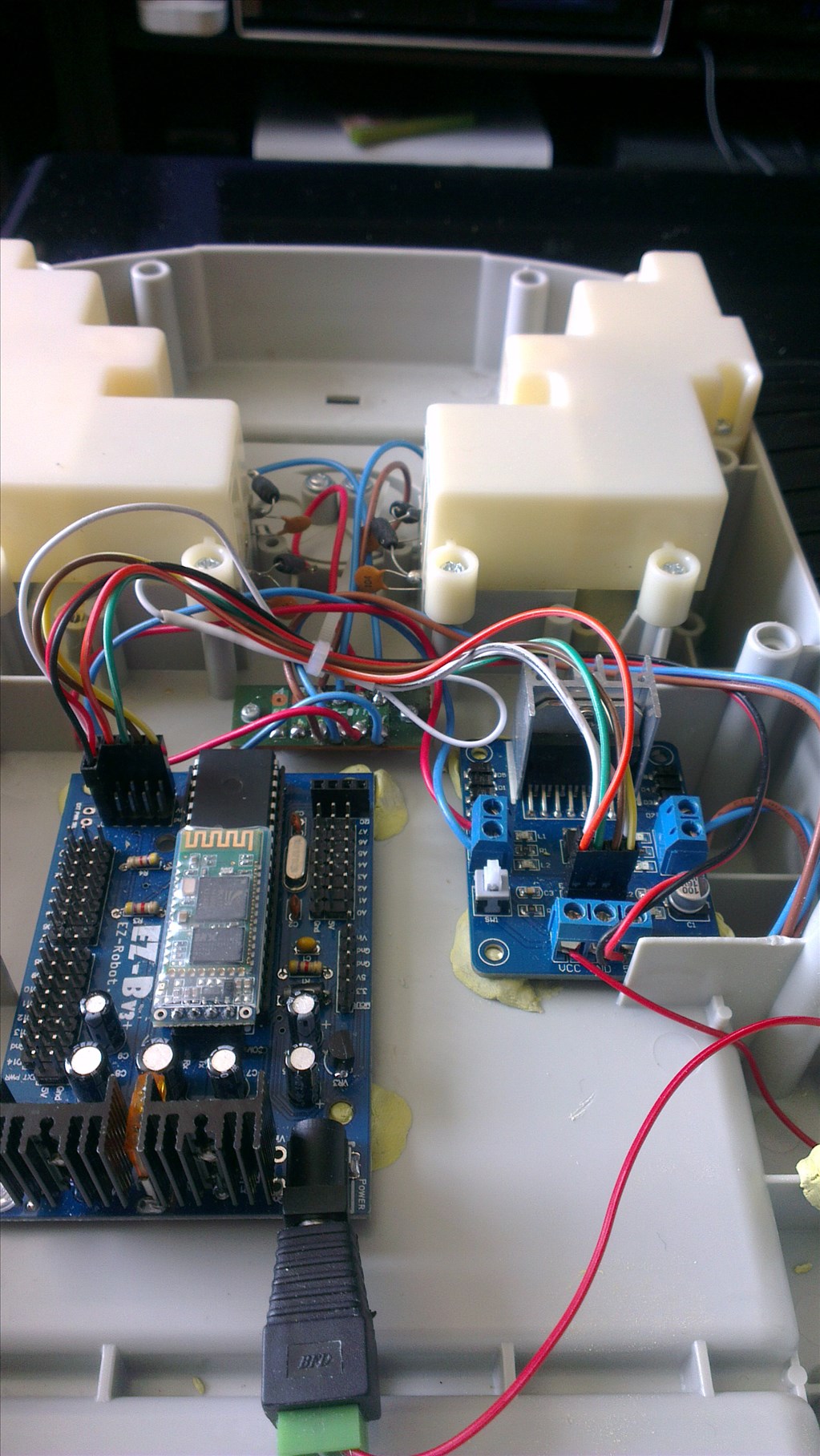
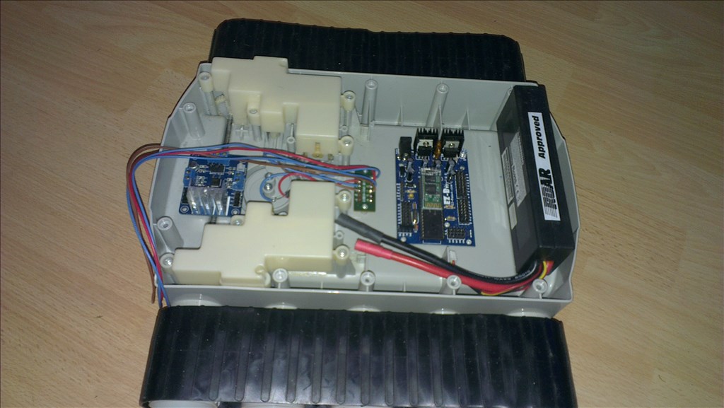
So far all I've done to the RAD is stripped it down - why they soldered every connection is beyond me!..
A lot of the choices I make on this project will be chosen by JARVIS. I will be adding some scripting so that I can ask him things like "What colour do you want to be?" and he will choose... this should make it interesting
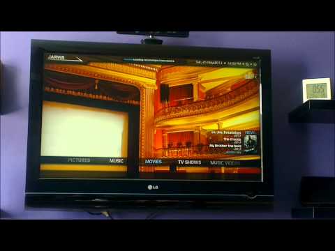
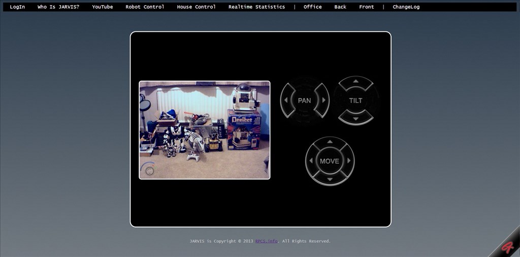
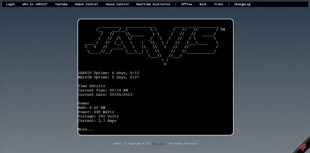
Like I said, his brain is existing and has been for around 2 years, with new features being added all the time. You know what, let JARVIS tell you himself a little bit about him
For more, check out Jarvis Youtube Channel or www.JARV15.com (under construction)

Discover more robots
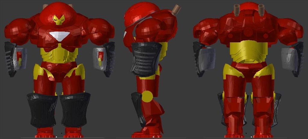
Jstarne1's Hulkbuster Ironman Suite , Lighting, Sound...
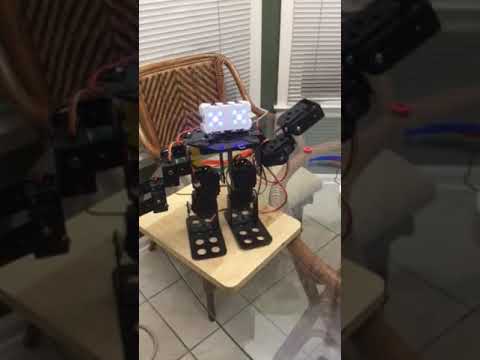
Ezang's My New Metal Robot With Voice Commands...

Well soldering is the "best" connection even if not the most practical. I bought a bunch of xt60 turnigy connectors you might find those useful in your project for quick disconnects that can also handle a reasonable amount of current. Looks like we are going to need to start a " Jarvis" robot club for all things Jarvis love the video
What happened to Melvin being your JARVIS physical form?
Any which way......... Awesome!
Keep us posted! Where'd you get the RAD from?
If i had known how popular the name Jarvis was on here back when I started him 2 years ago I would have chosen a different name but everything is coded around the pre-word Jarvis now and there is no way in Hell I will be rewriting 2 years worth of code for a name change.
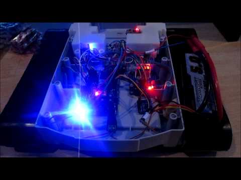
A lot of planning needs to be done too, since really he needs a screen. I have ideas, one includes a faux holographic display (untested but in theory should work), although that would be a huge power drain and I only plan to run it on one, maybe two 2S 5000mAh LiPo batteries (they couldn't fit better if they were designed for the base).
I have a bunch of connectors for the batteries since I needed them on Melvin and it was cheaper to buy 10 sets than 1 set. But typical of me, again I want nothing on show, not even the charging port or on/off switch.
Jarvis was never going to have a physical form, since Mr. Stark's doesn't have a physical form. But I picked up the RAD over Christmas (on ebay, 10, couldn't say no to that) and since then have been patiently waiting for Melvin to be finished so I can start on Jarvis, but 5 months of waiting is too much, especially as I have the EZ-B ready and waiting for him
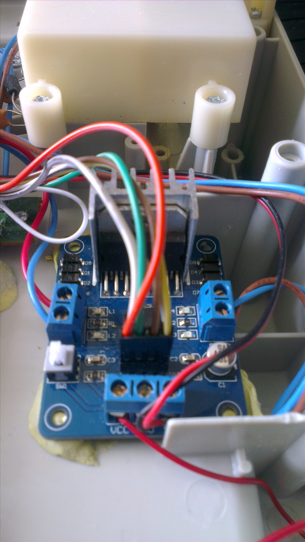
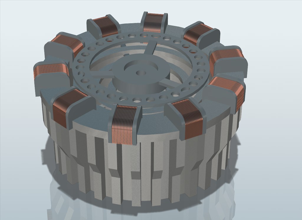
I'm still not sure what he will do as far as functions go with ARC. Chances are he will be very basic running a hbridge on the original motors for driving around, pan head, camera and a bunch of lights... plus the ARC Reactor. But we will see what Jarvis says when I ask him A robot deciding it's own fate is kinda cool.
Stripping down the RAD
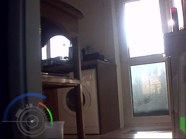
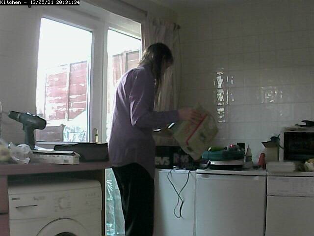
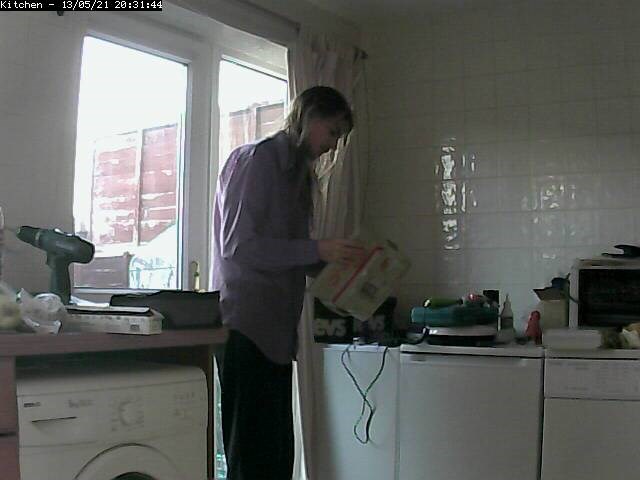
Apparently it's blocked in Germany, sorry for that.Excuse the poor camera, it's one of my IP cams and it decided it needed IR on which made me look grey, I'm not grey...
Awesome Rich! ..Great vid and Highway to Hell tune is cool ...with so many robot ideas it is hard not to be distracted and begin another robot. I really liked the Jarvis voice..very smooth...I suppose with all the Jarvis robots being developed a number might have to added or letter..Jarvis1( for Rich) or JarvisR...JarvisJ (for Josh).... If your on the "Highway to Hell" Rich your certainly with all your friends , EZ forum community included.
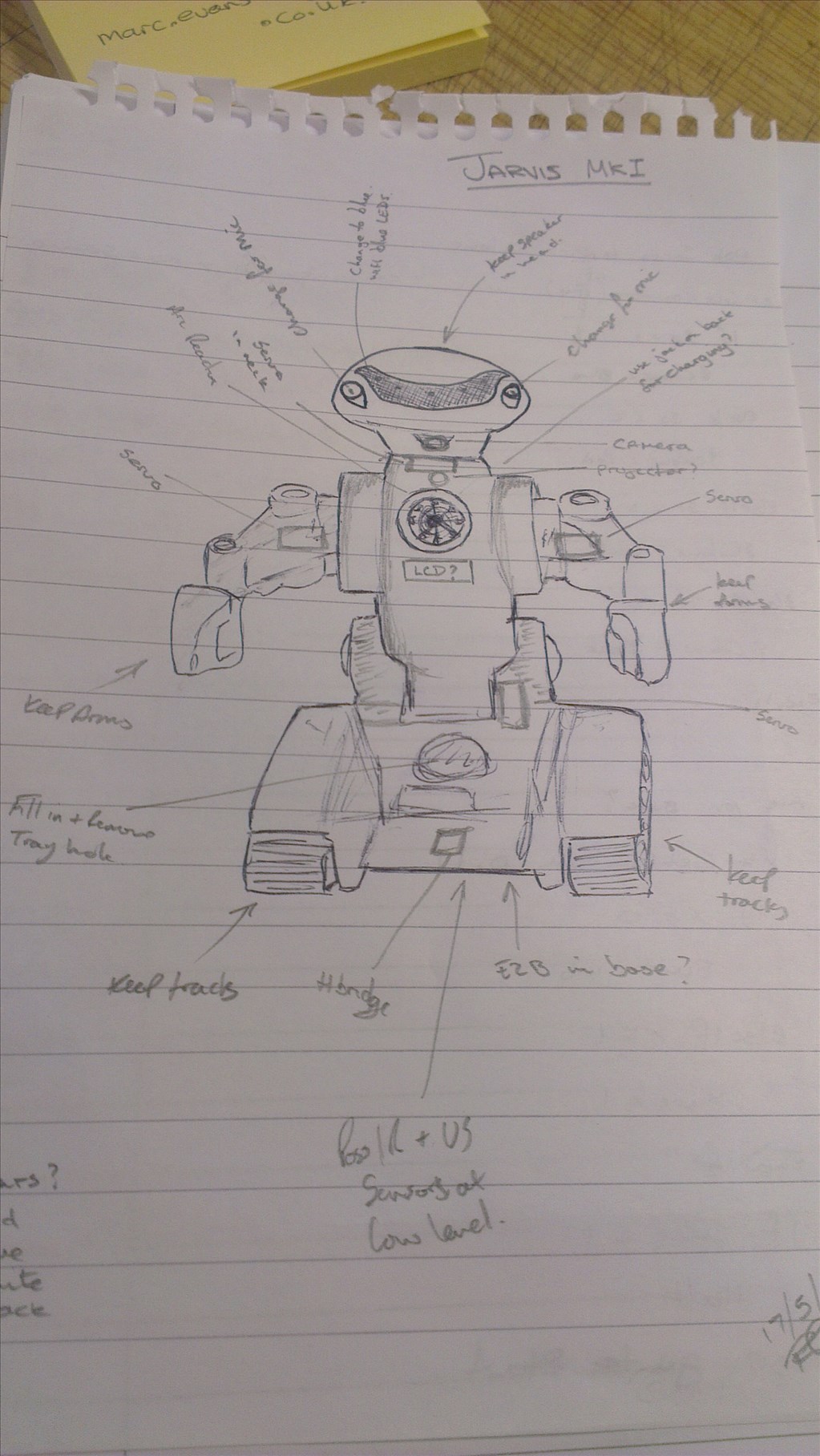
I shouldn't be left alone at work, I tend to doodle...
We will see how close I am once it's done, I suspect this will be another one which I'll constantly be improving too but we will see.
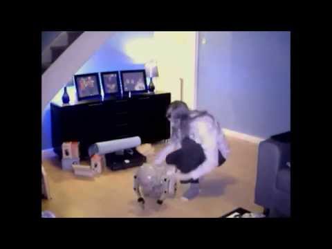
Rich, I did a RAD robot build 10 years ago, I just found this old photo.
I like the RAD robots, I still have a few left in the loft!
@toymaker - that guy has some serious ears!