


-635353562186322812.png)


Hi all,
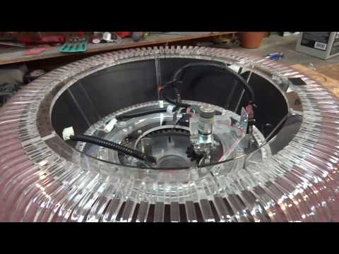
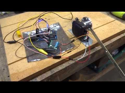
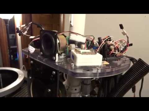
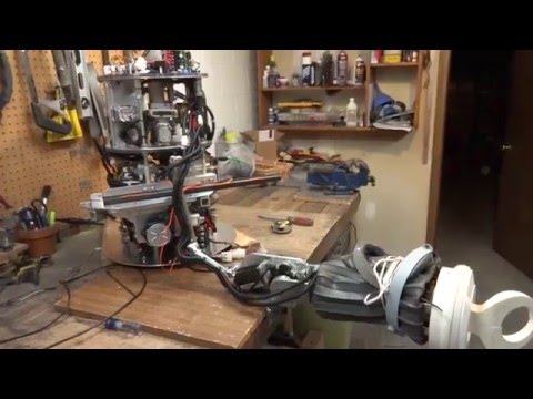
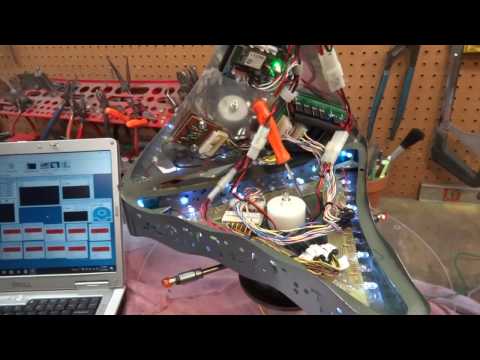
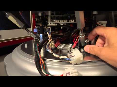
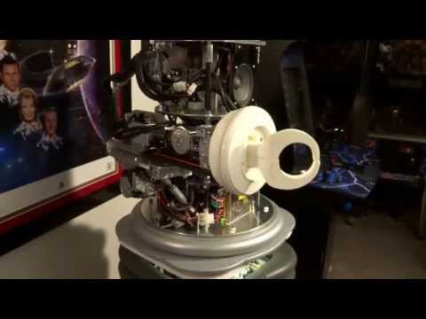
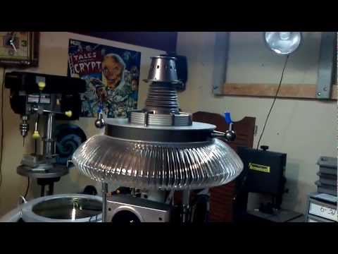
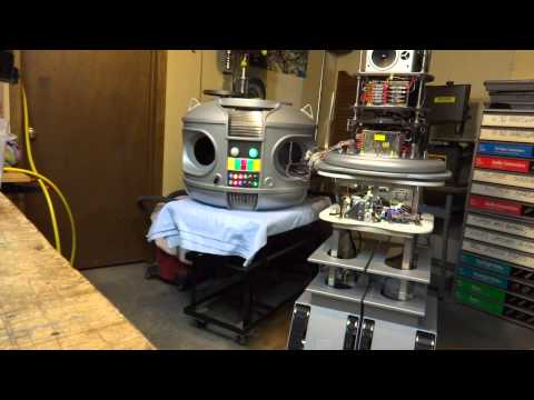
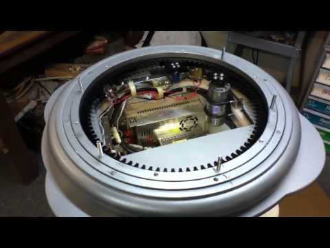
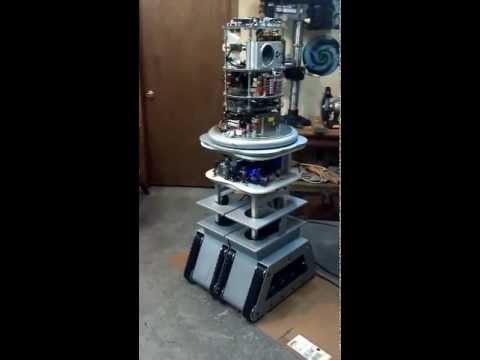
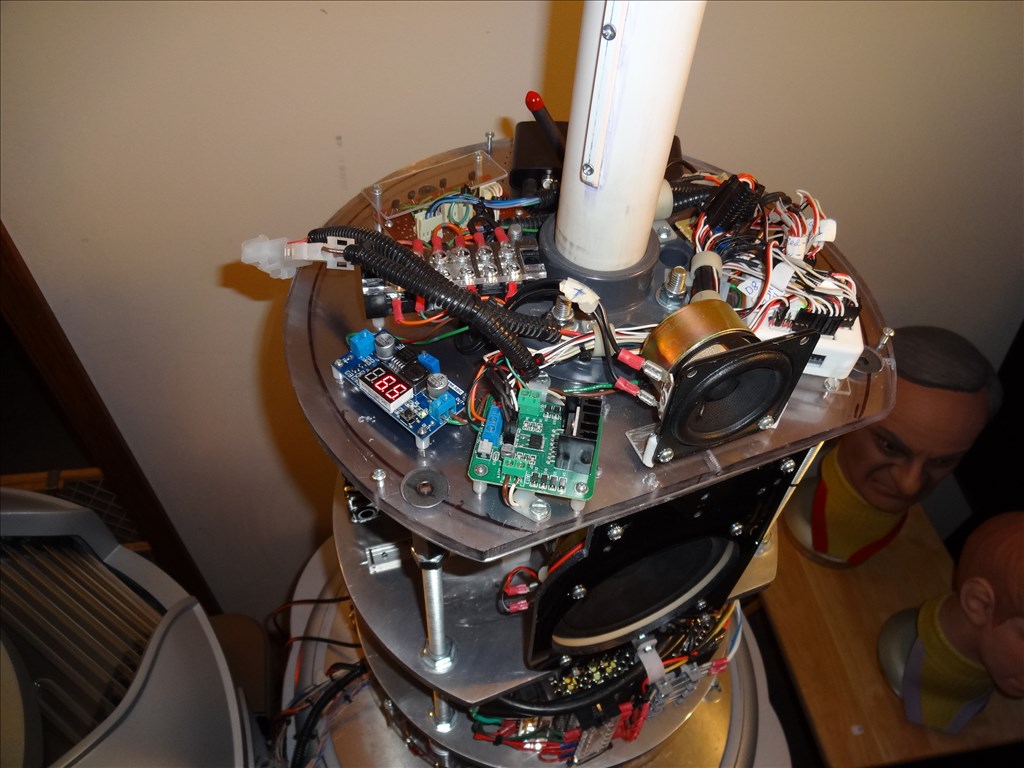
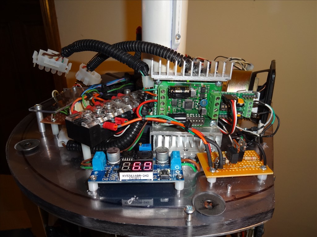
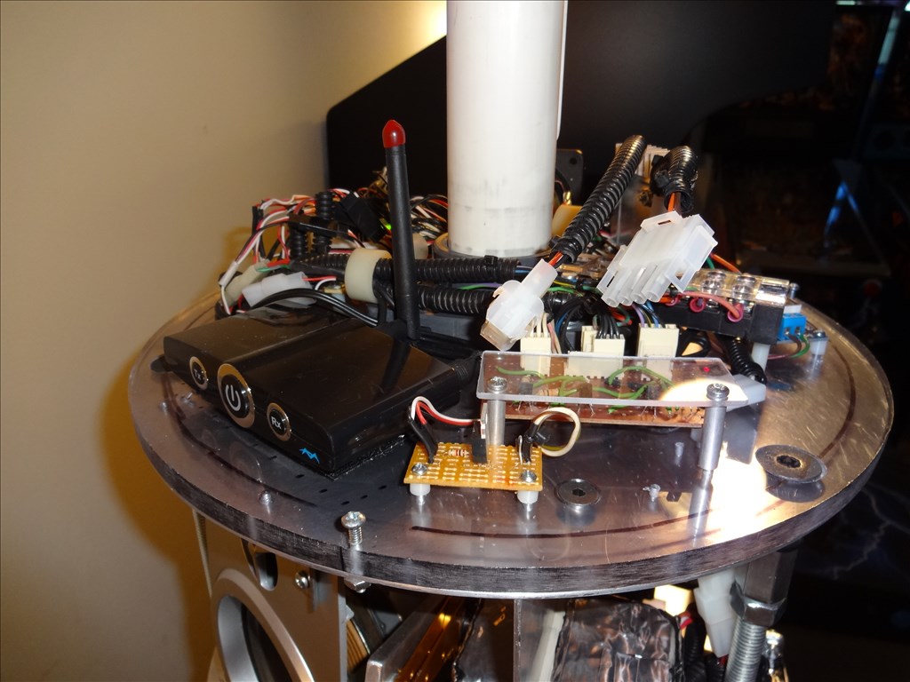
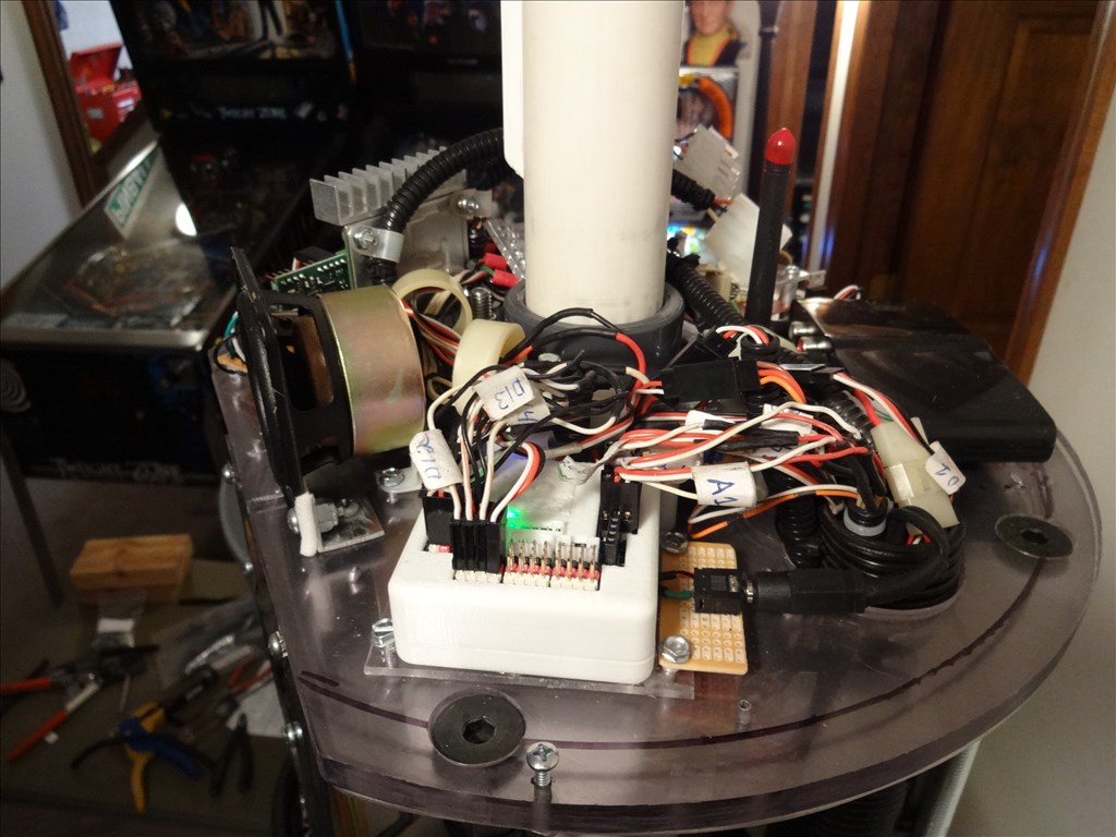
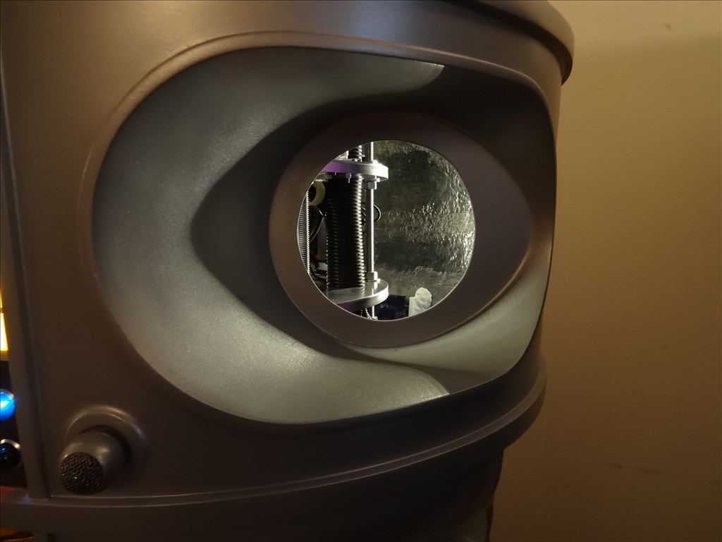
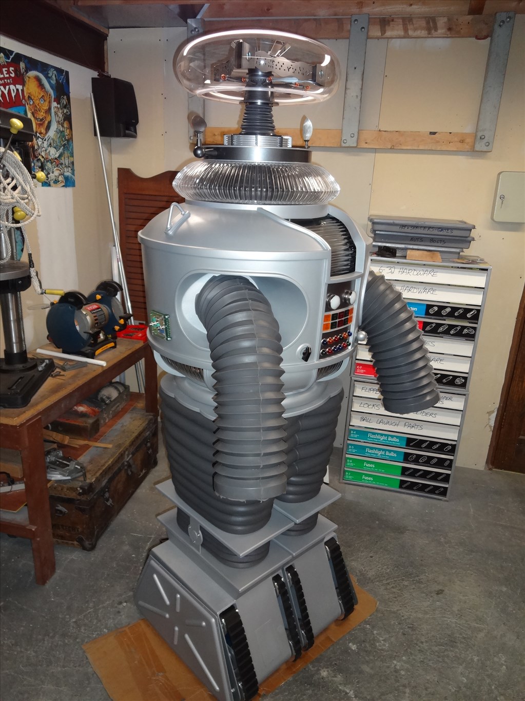
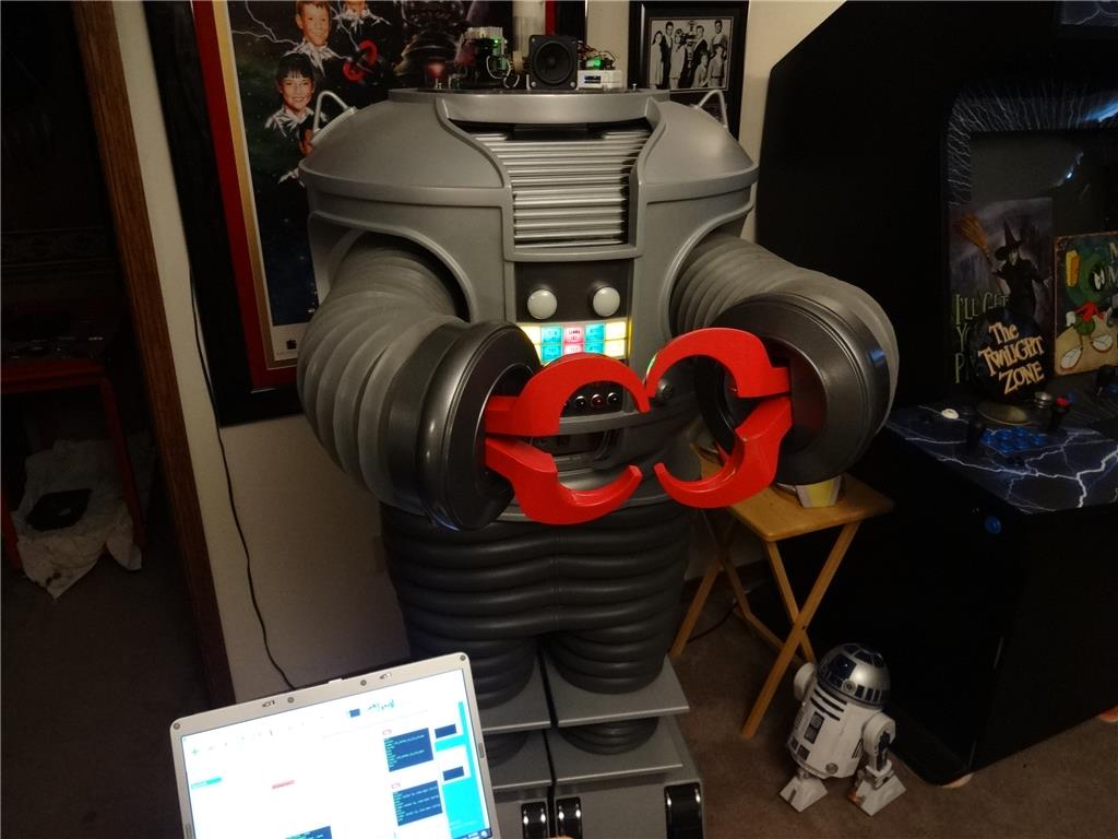
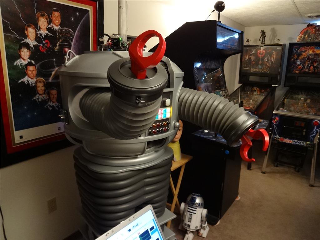
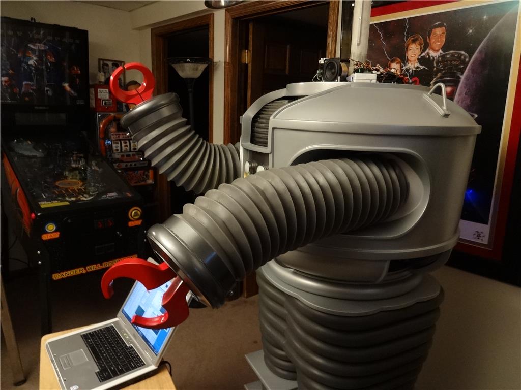
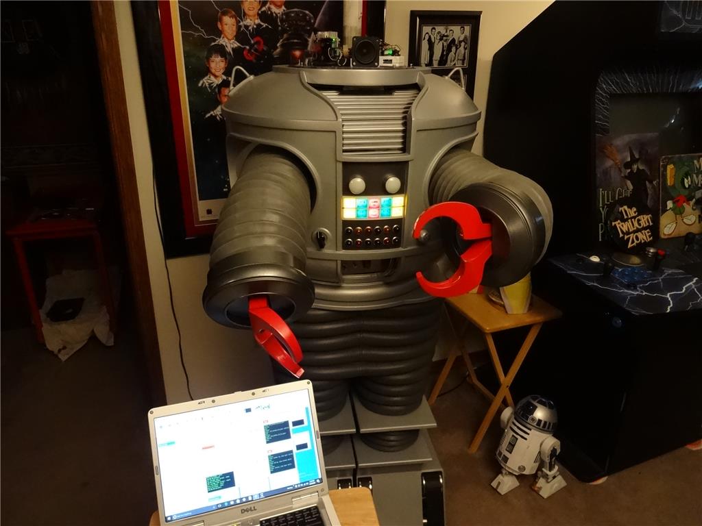
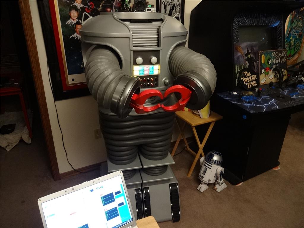
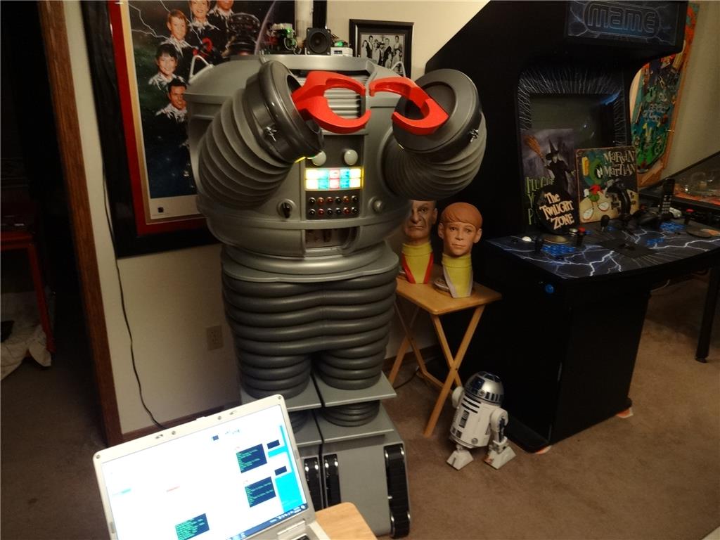
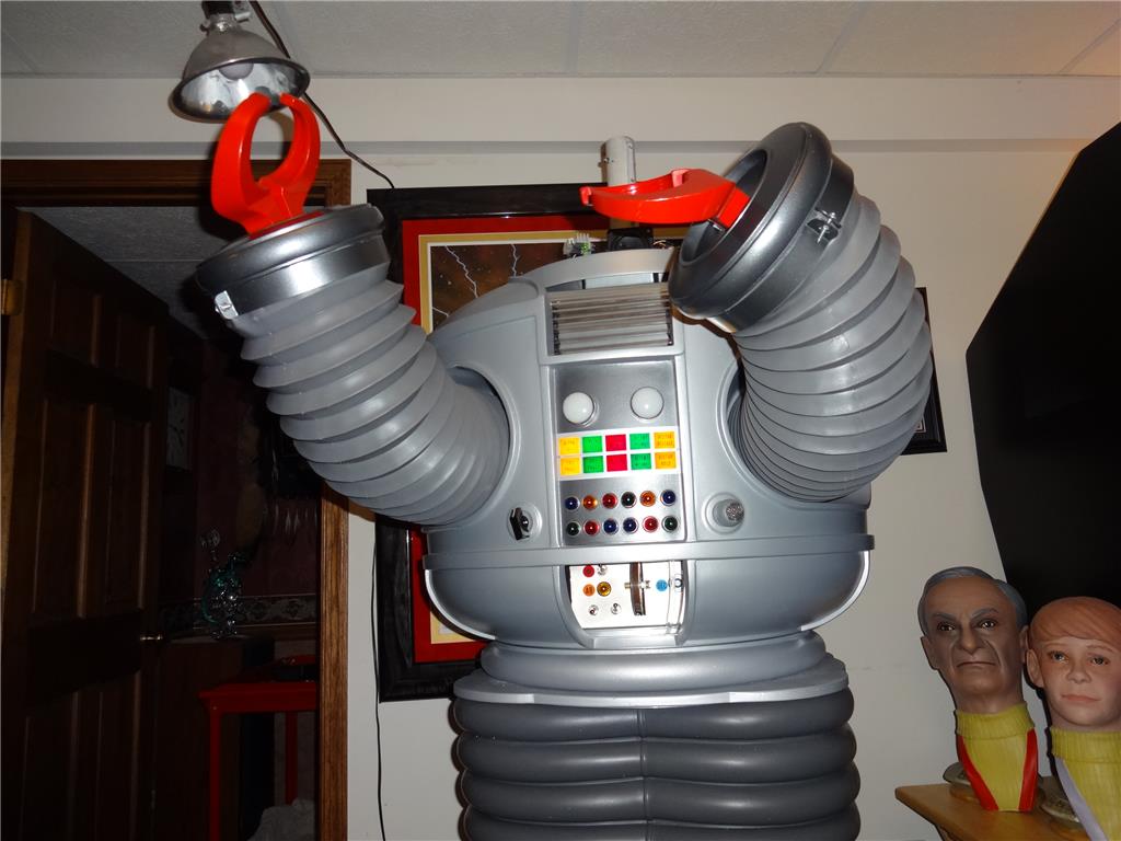
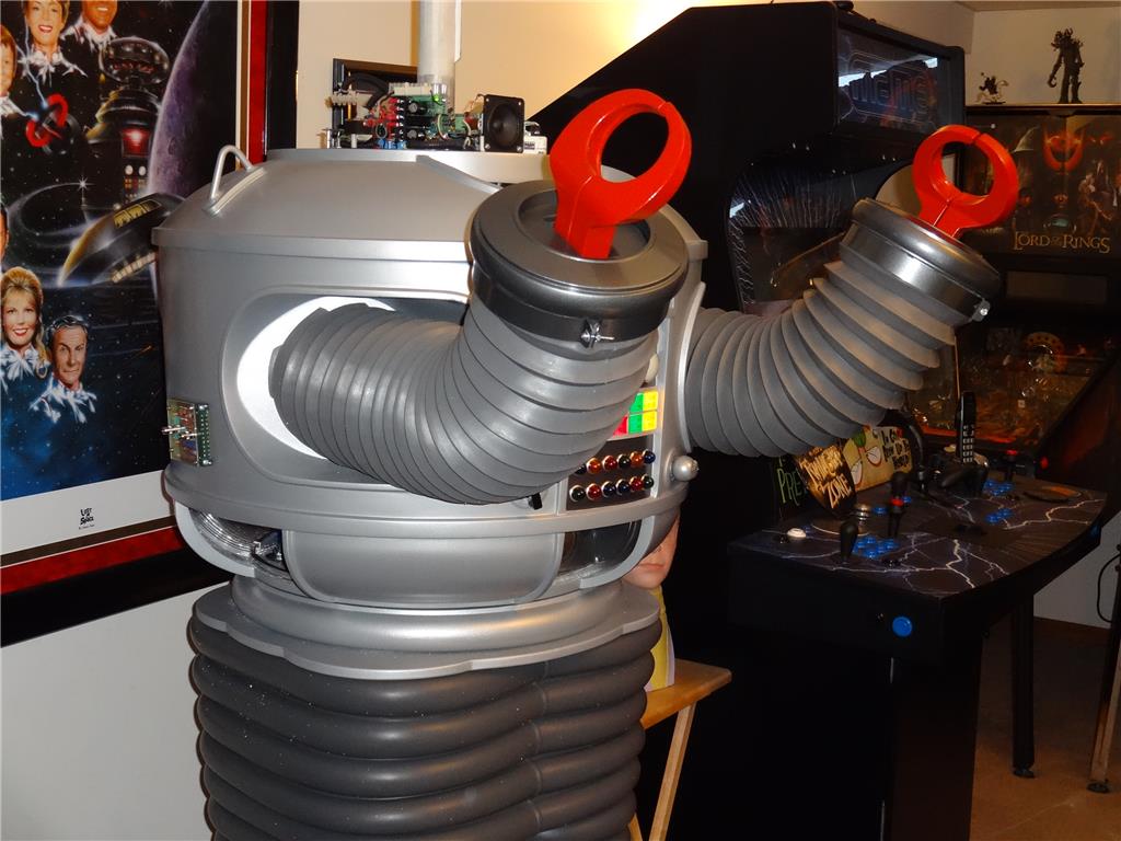
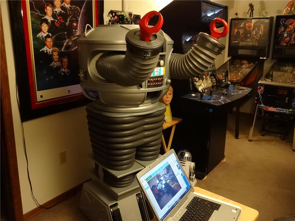
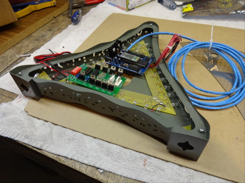
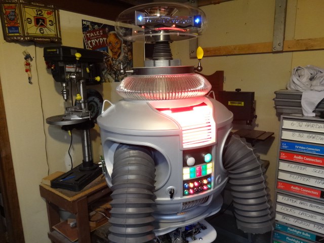
I'd like to share a video I just took of my full size Lost in Space B9 robot that's controlled by two EZ-B controller boards. Right now they are controlling limited movement and voice response of a few motors, lights and sound files played from a Sparkfun MP3 Trigger board. Although I'm just starting with the animation and have more building on the actual robot the result (mostly thanks to the EZ Robot controller board) is shocking. Please have a look at this (4 minute) You Tube vid and enjoy.
Please excuse some Technical camera lighting and sound issues. This is the first time I'd made and posted a vid online.
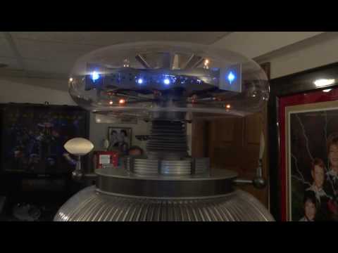
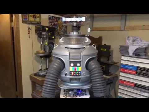
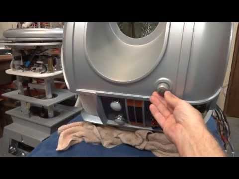
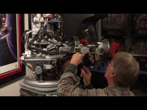
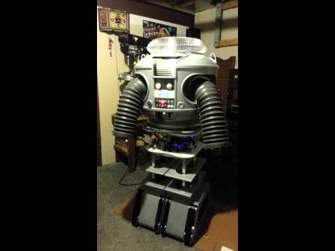
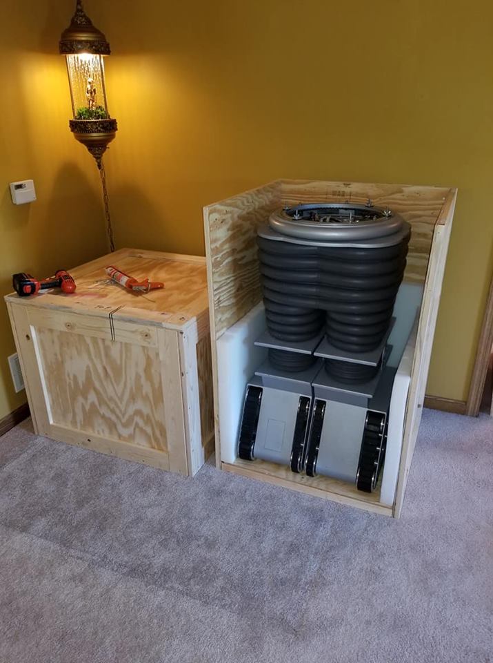
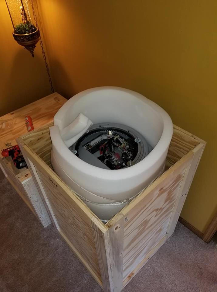
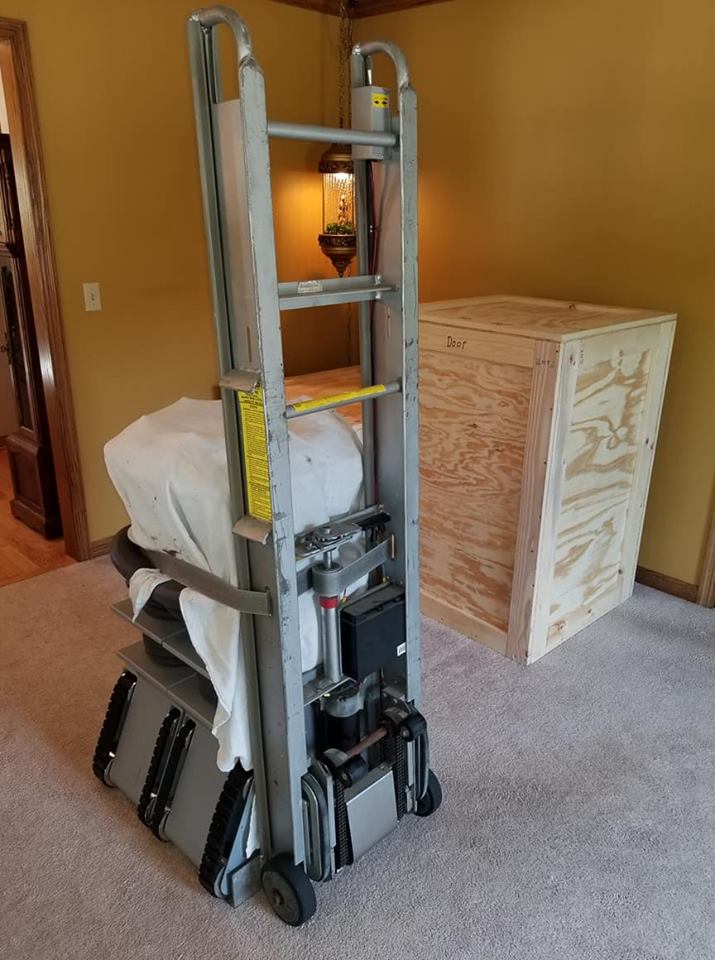
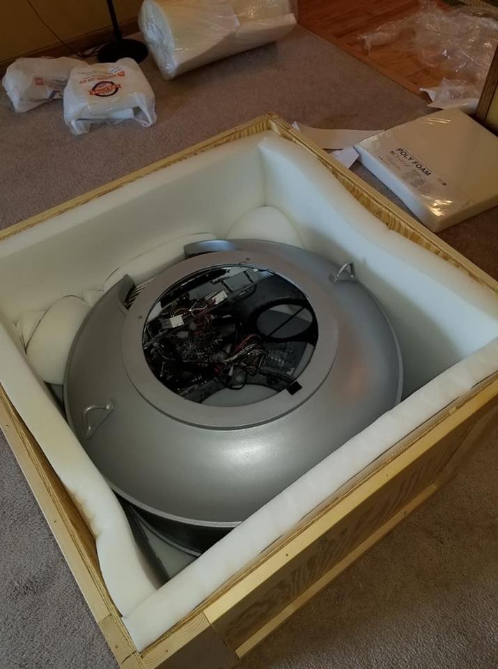
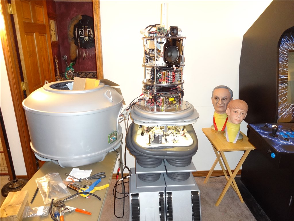
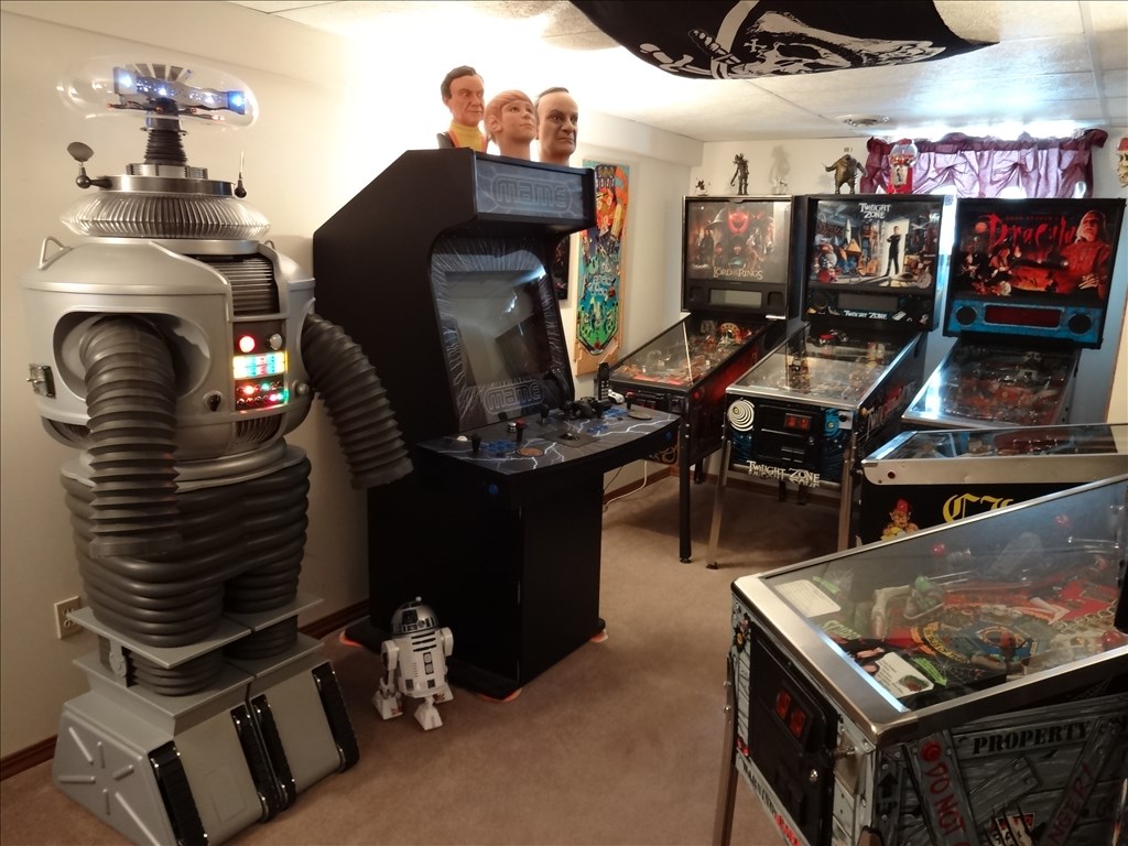
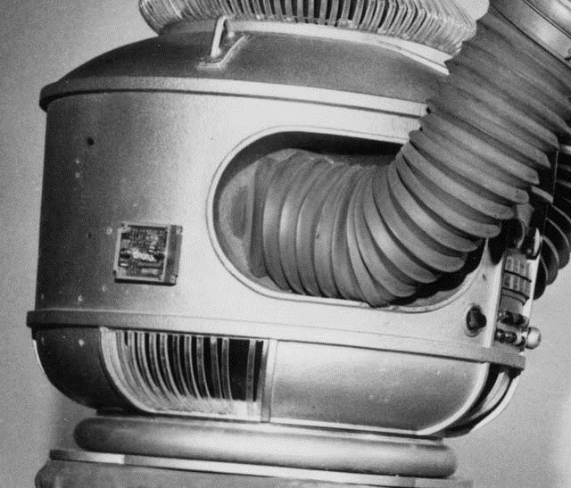
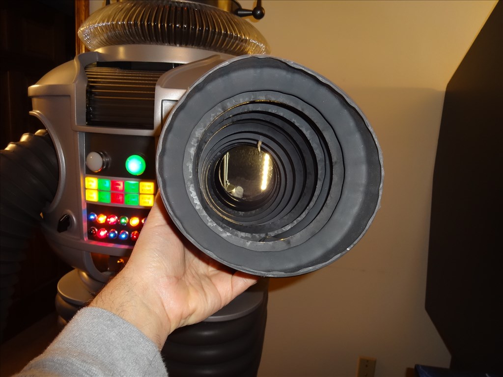
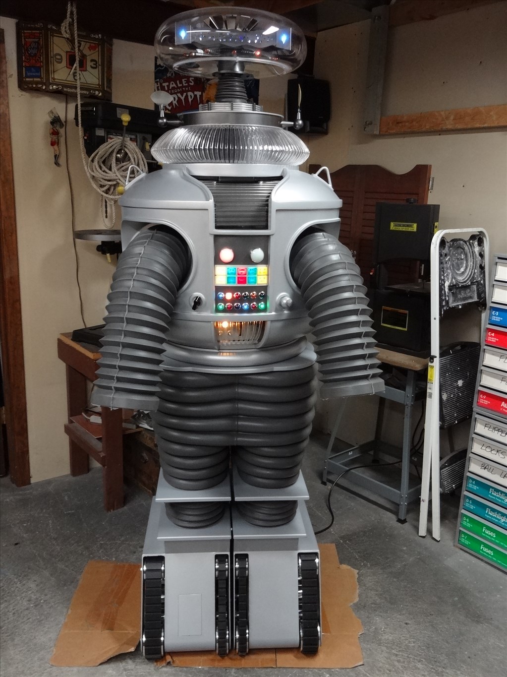
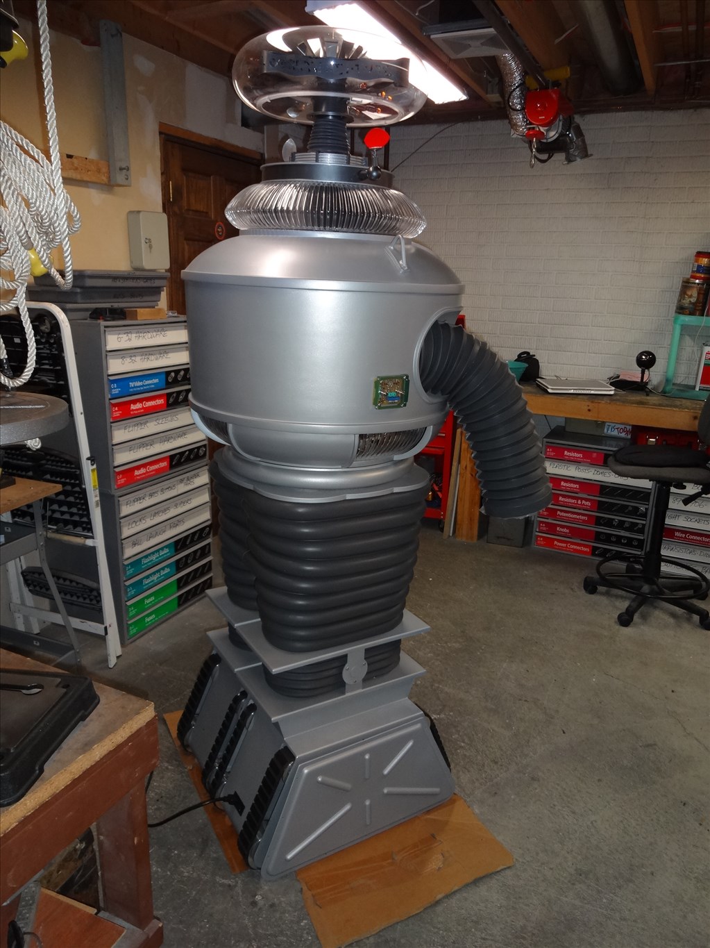
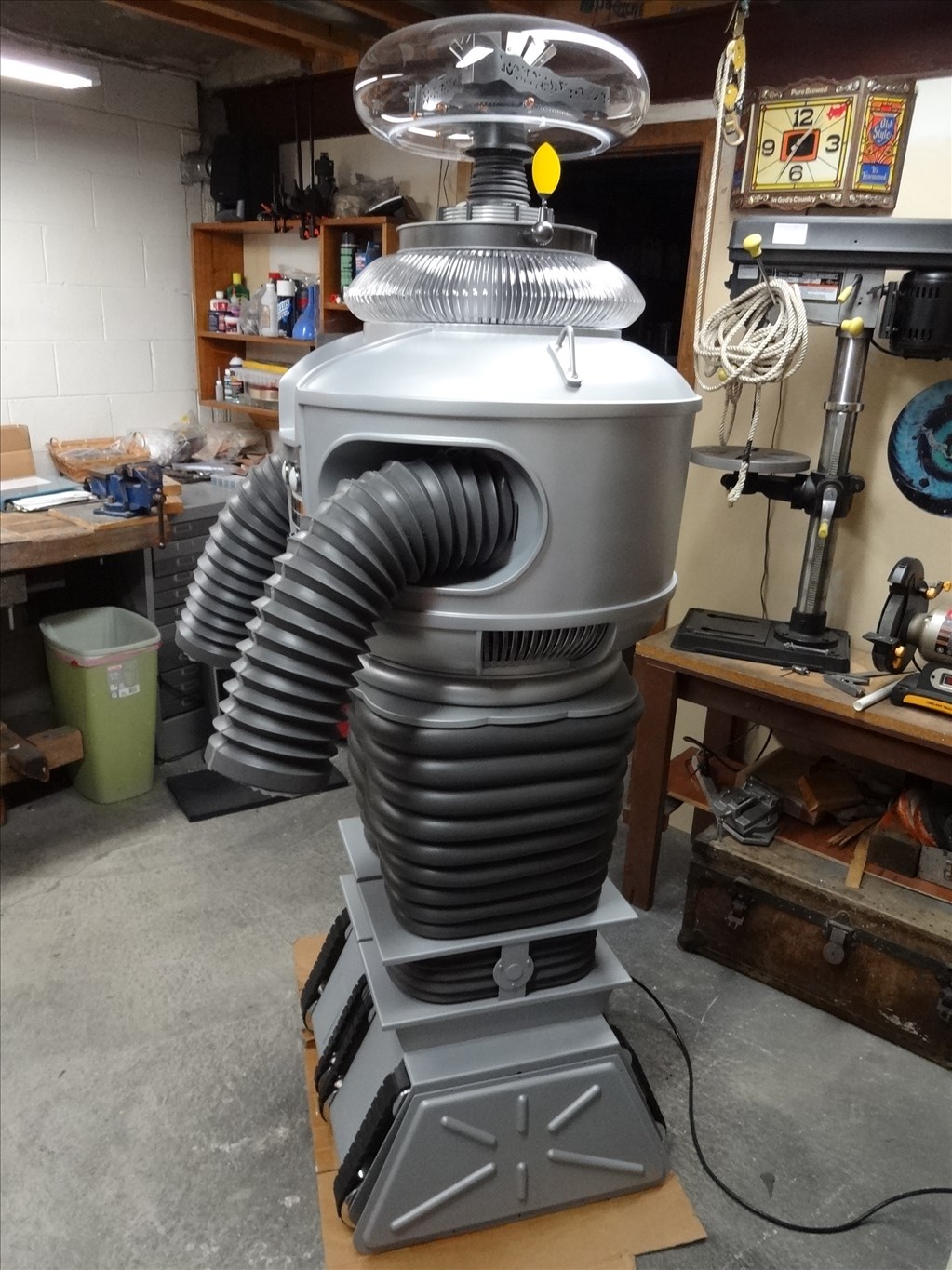
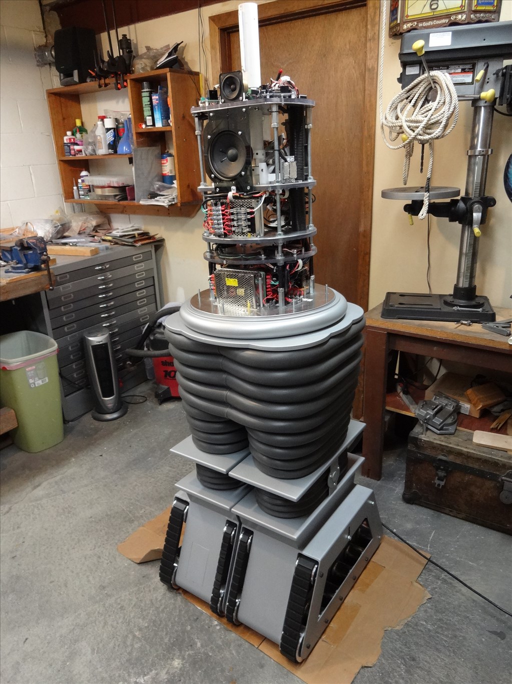
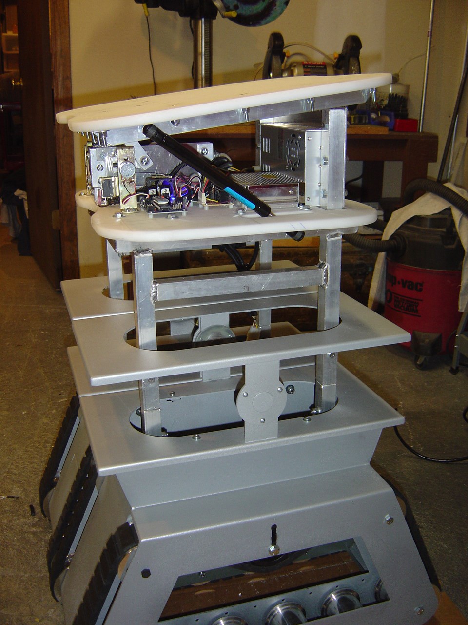
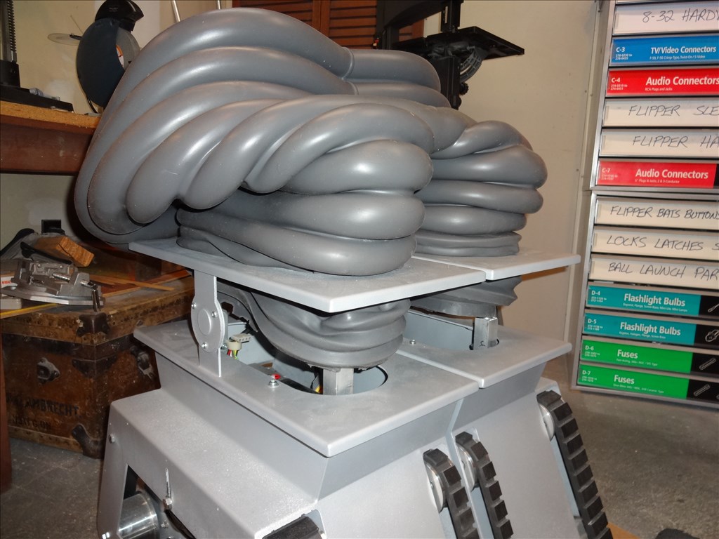
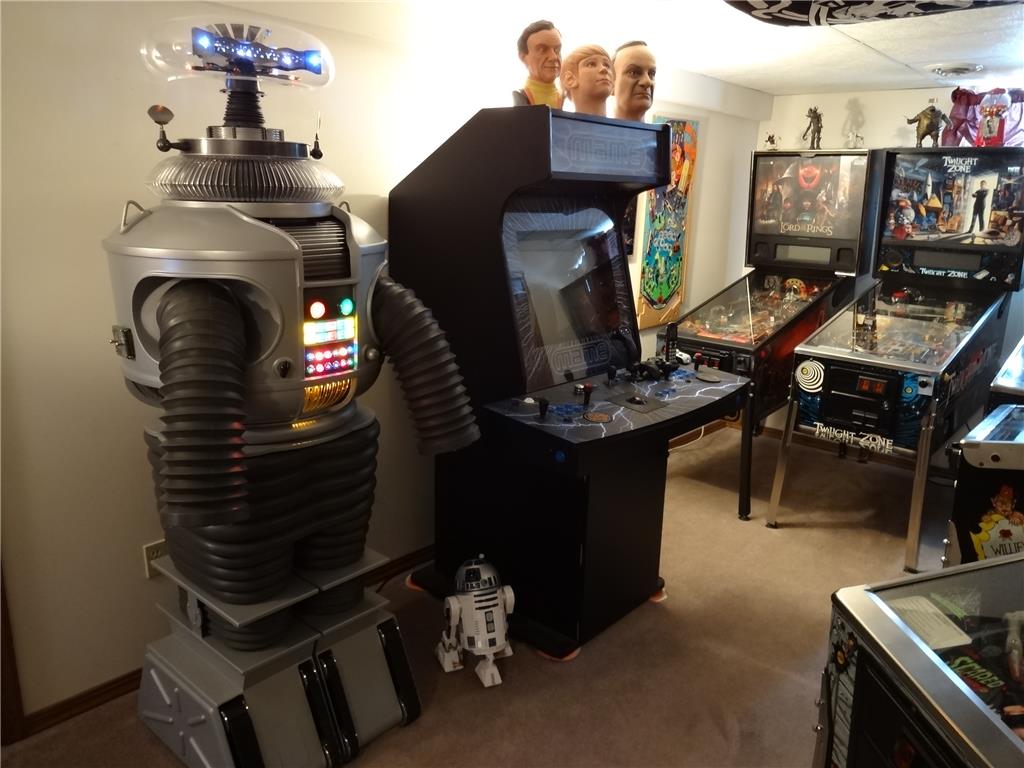
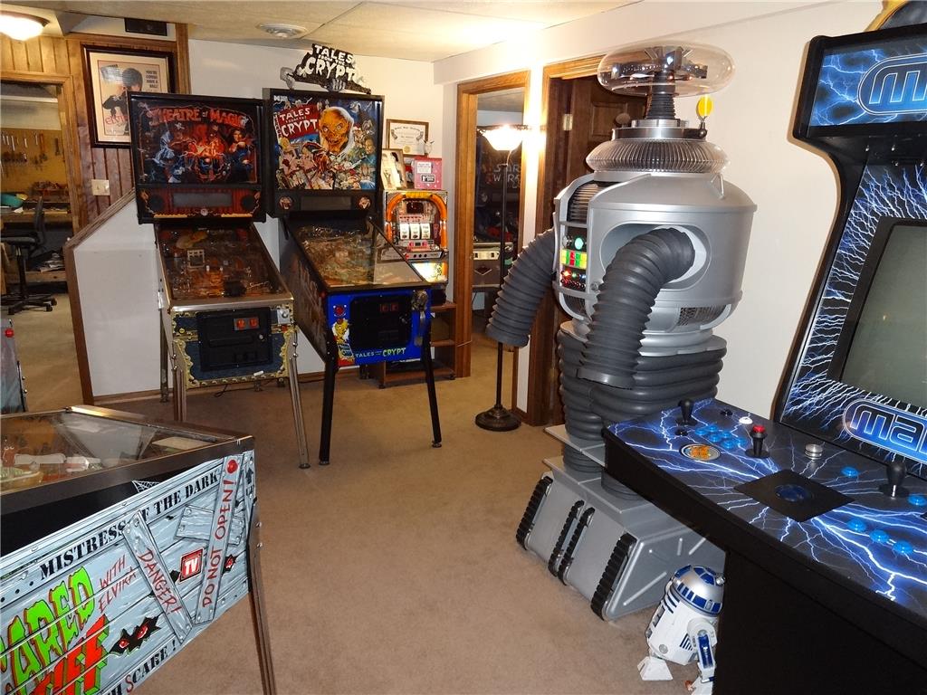
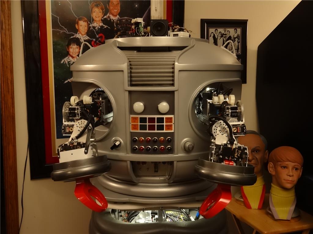
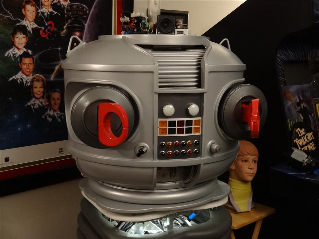
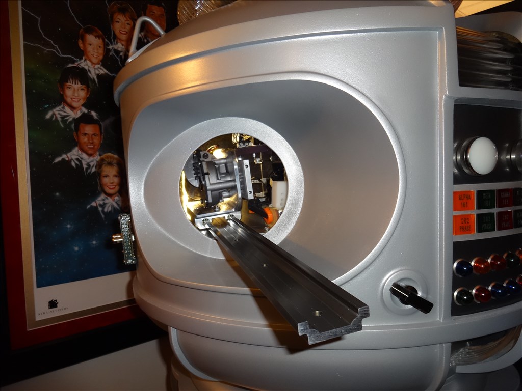
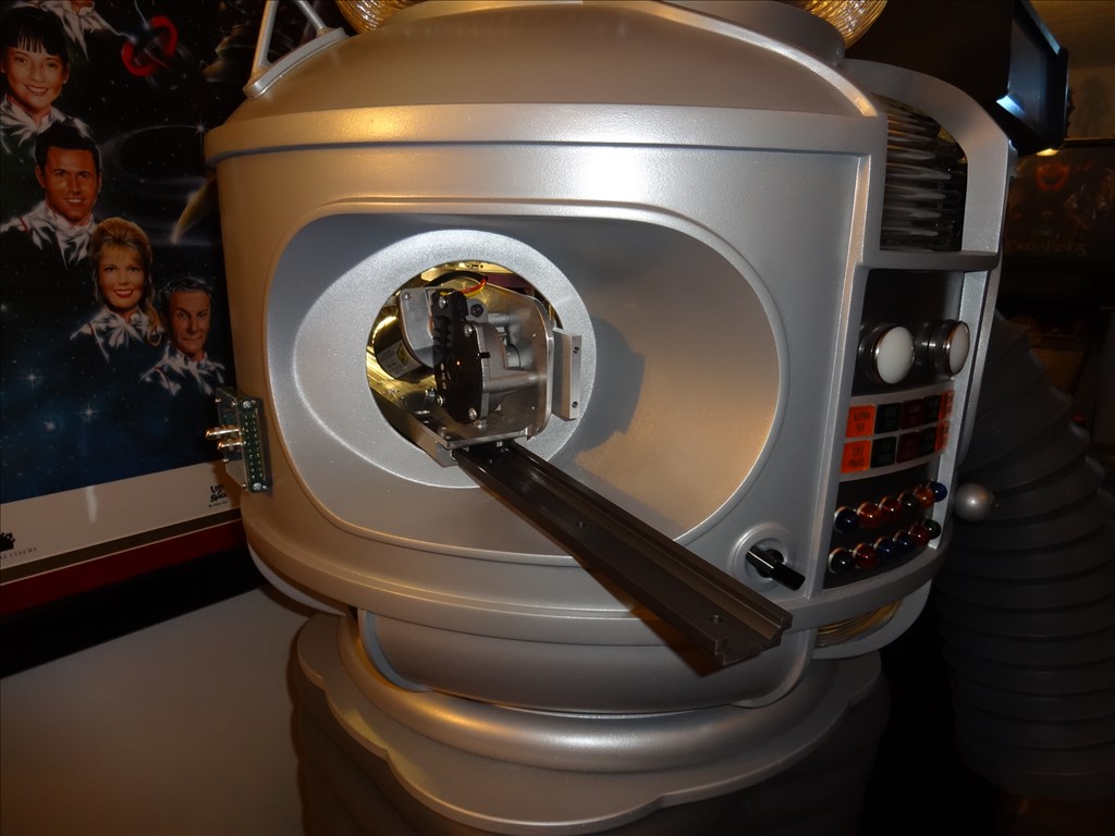
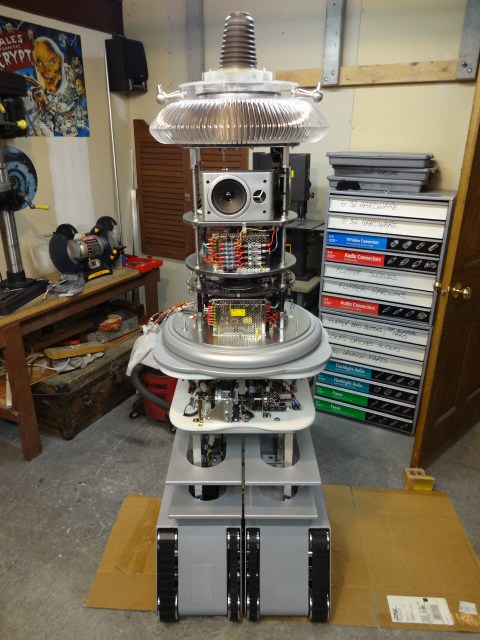
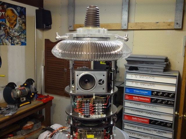
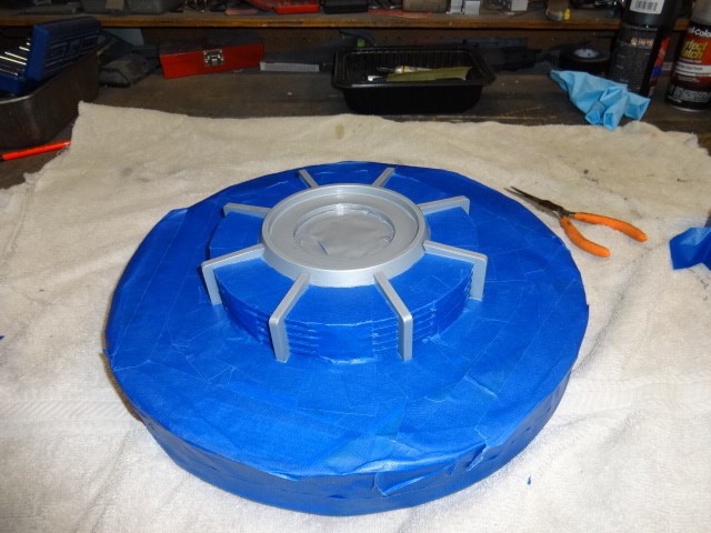
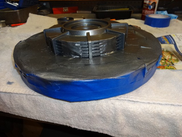
EDIT 8/2/13: Just realized I have no good pictures of how my B9 will look when complete. Here's one of the actual TV robots from the 60's TZ show Lost in Space and one recent shot of where I'm at with my build over 1 1/2 year after I started. Enjoy:


Thanks, Dave Schulpius
Discover more robots

DJ's And Now For Something Completely Different (Pdp-8)

Leversofpower's Cutting My Teeth. The Floor Crawler

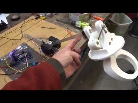
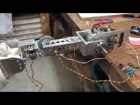
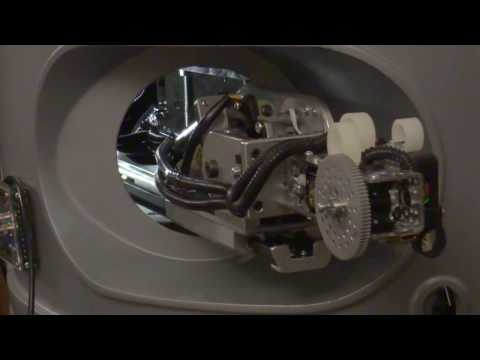
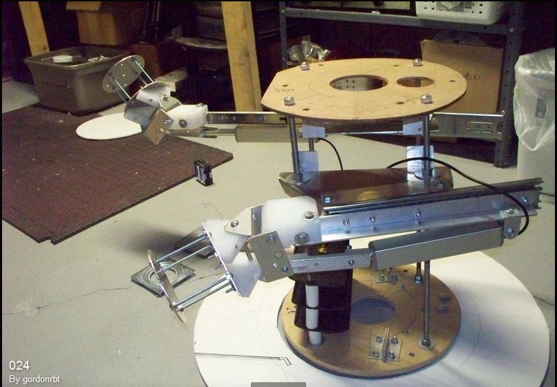
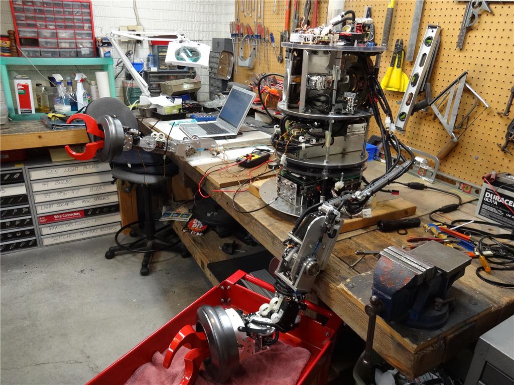
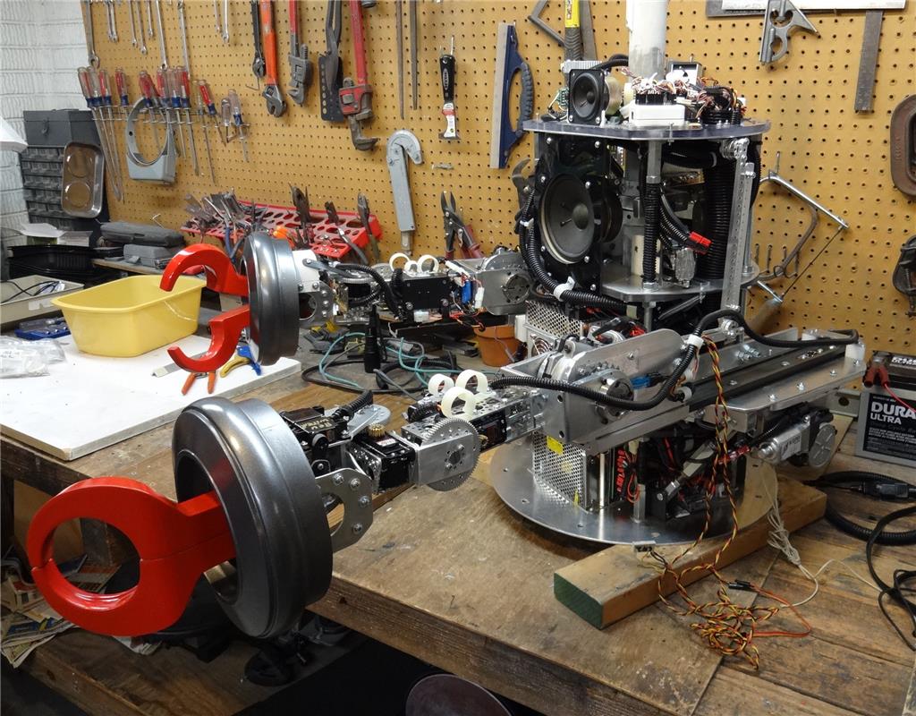
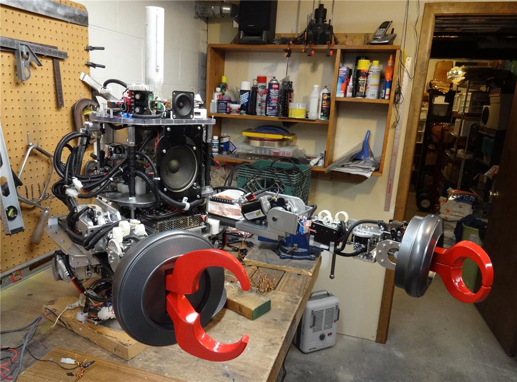
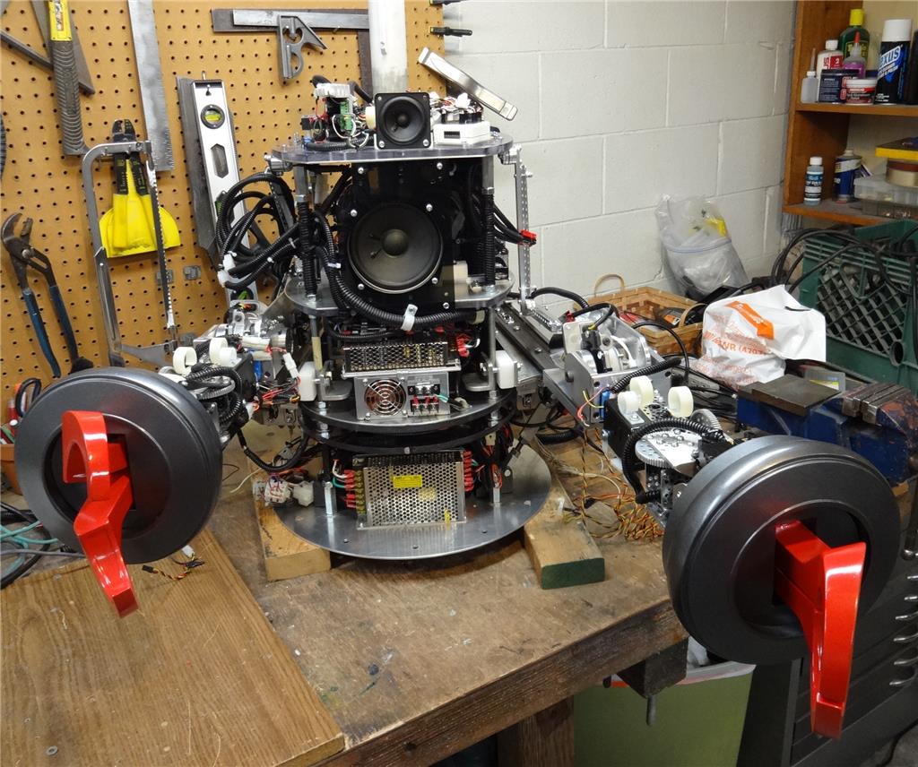
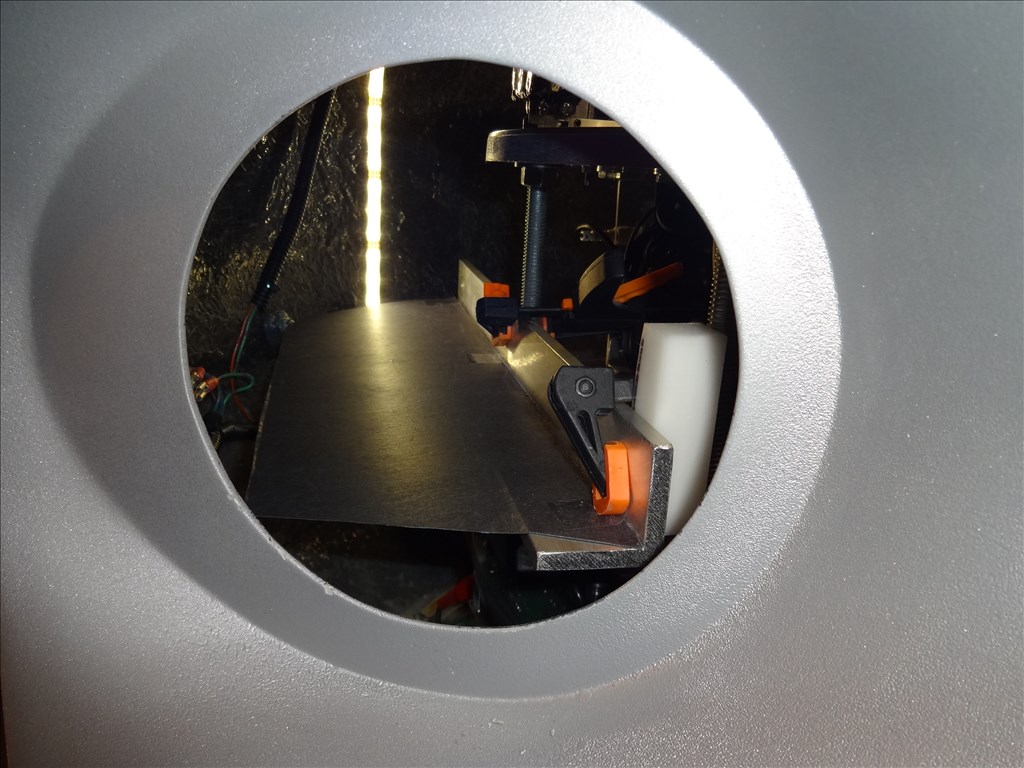
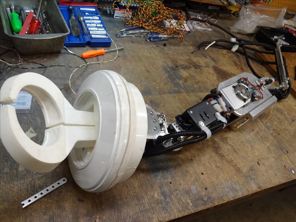
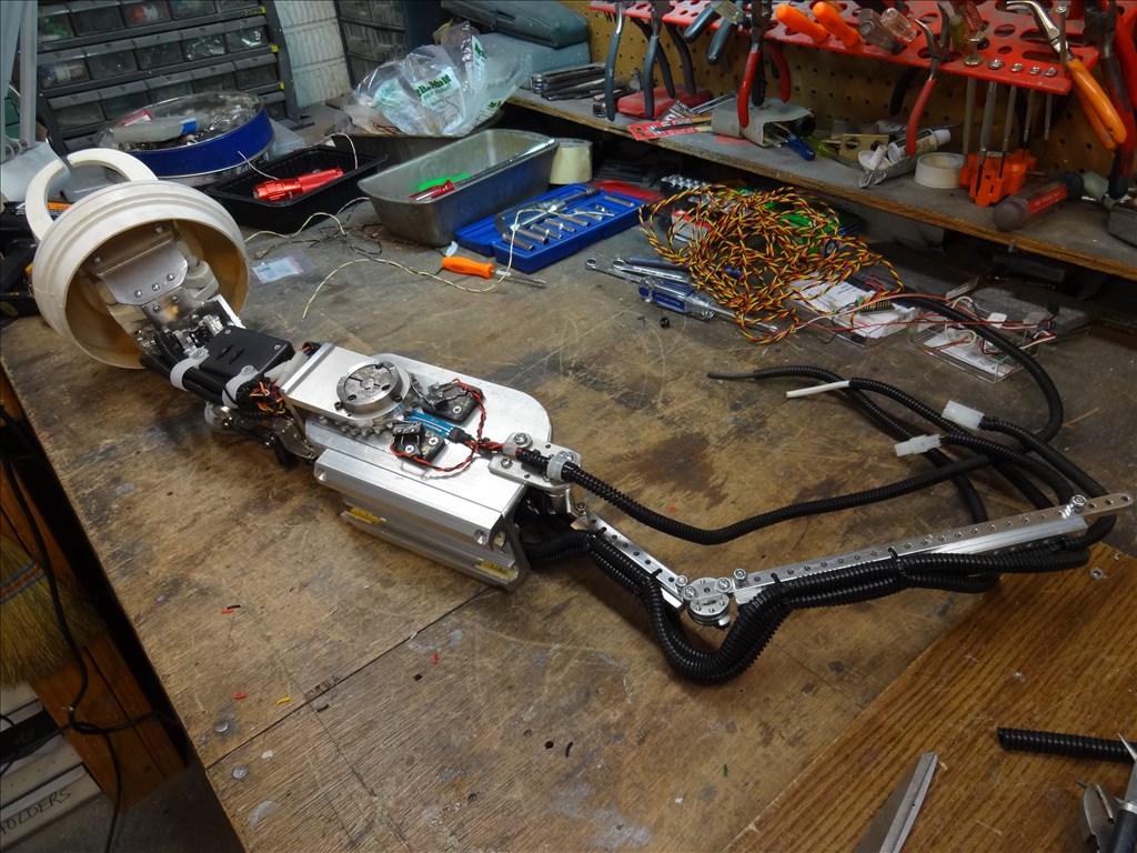
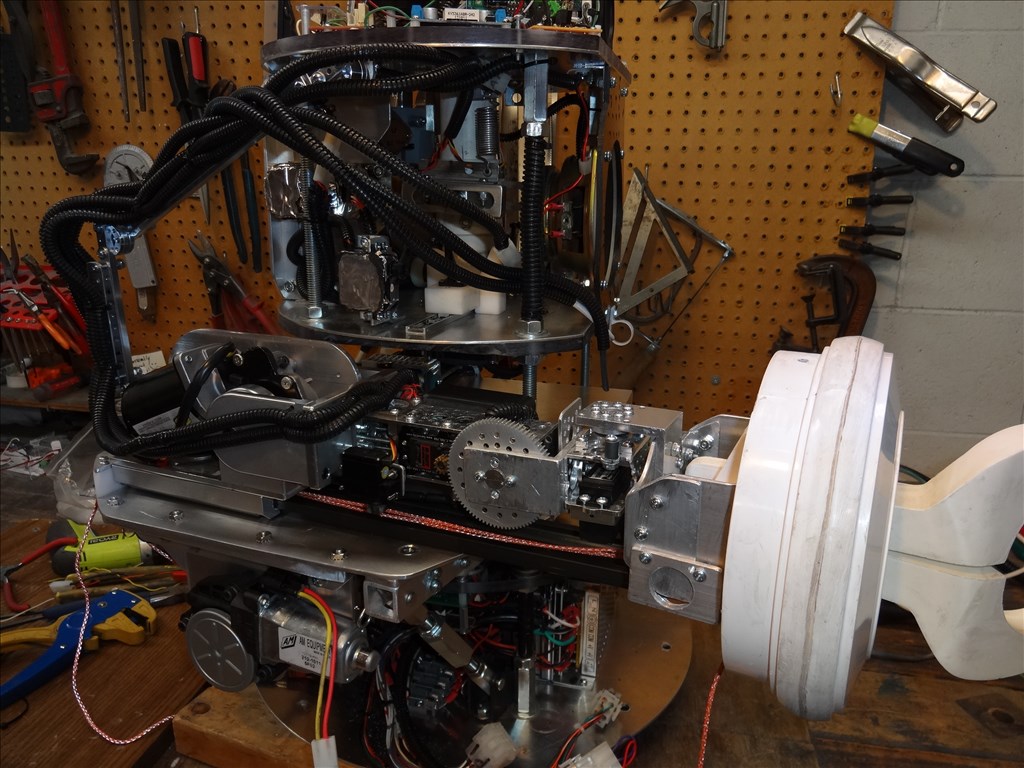
I've been working a lot on my arm design. There has been a lot of false starts and redesigns. I think I finally have a working design that will fit into my 5.5" arm hole and have enough strignth and dexterity to make me happy.
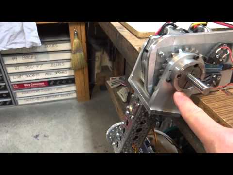
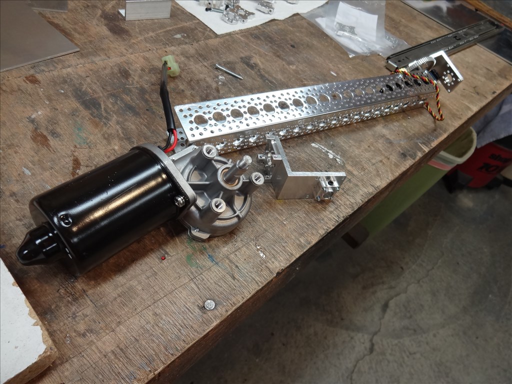
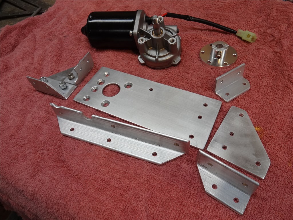
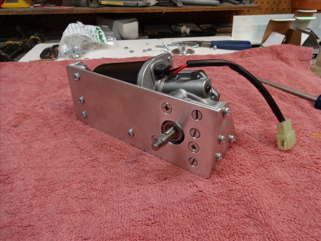
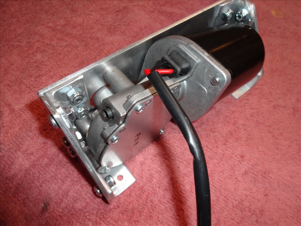
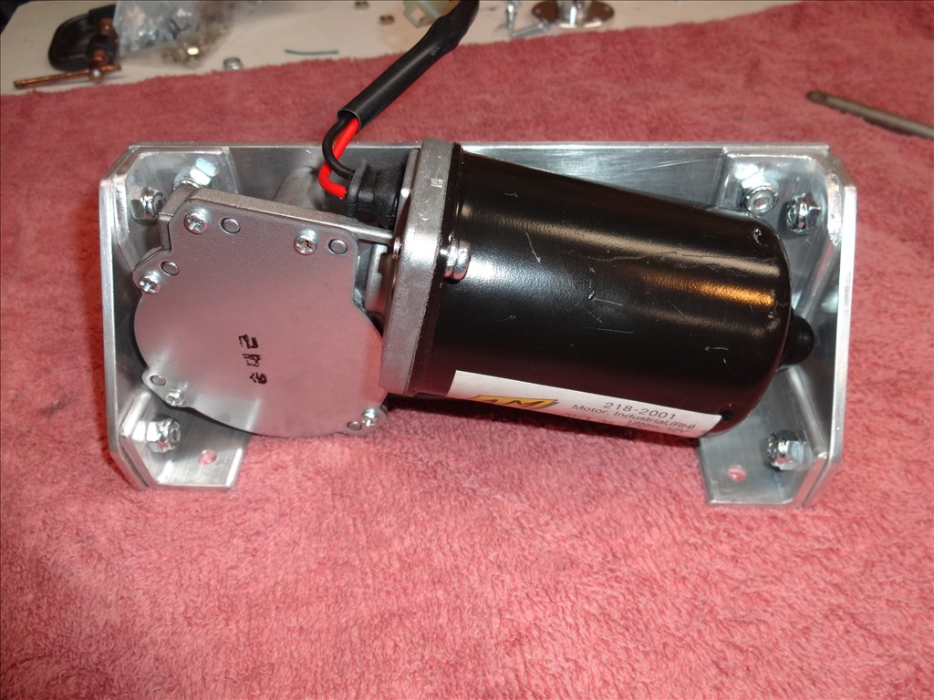
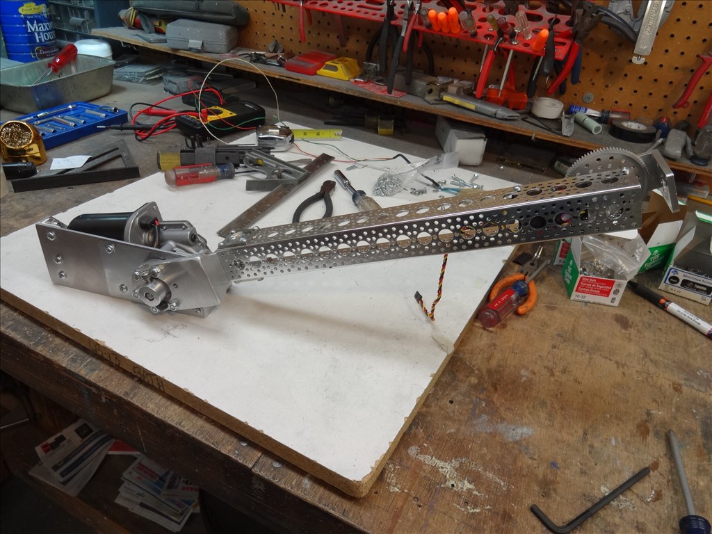
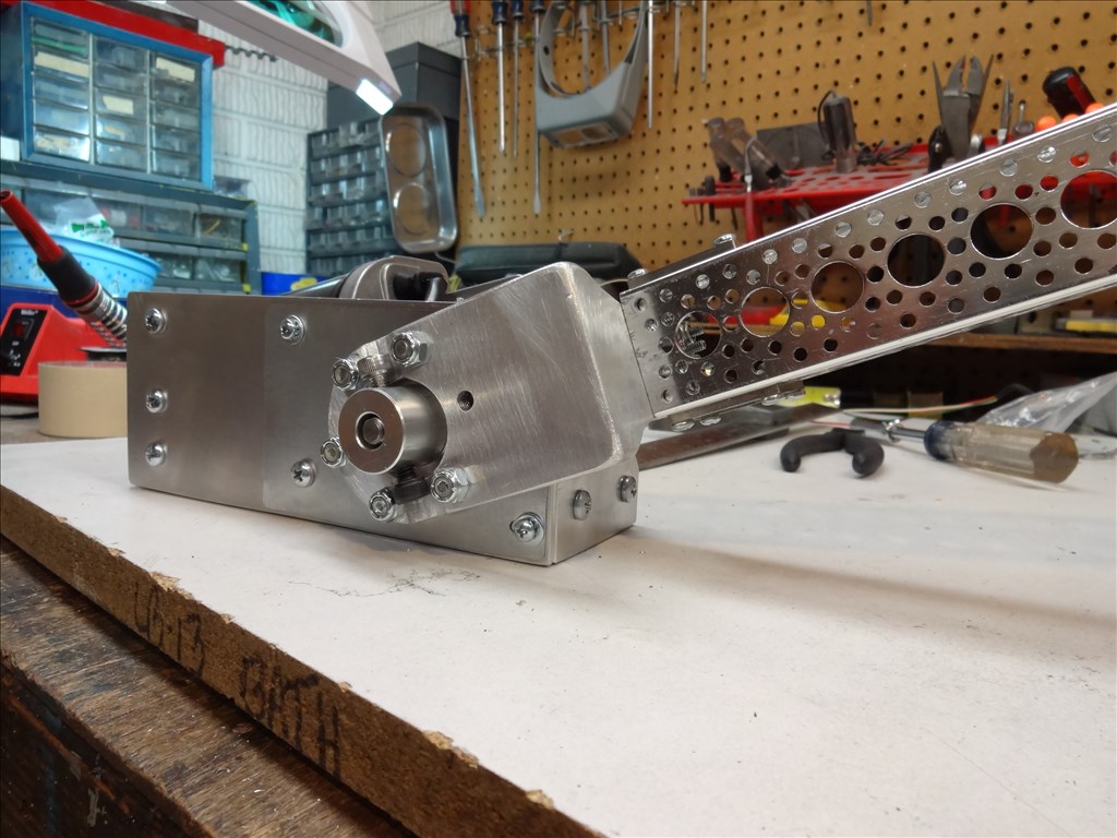
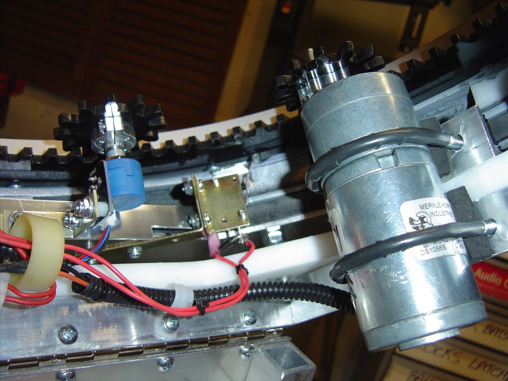
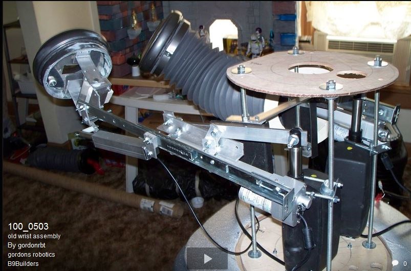
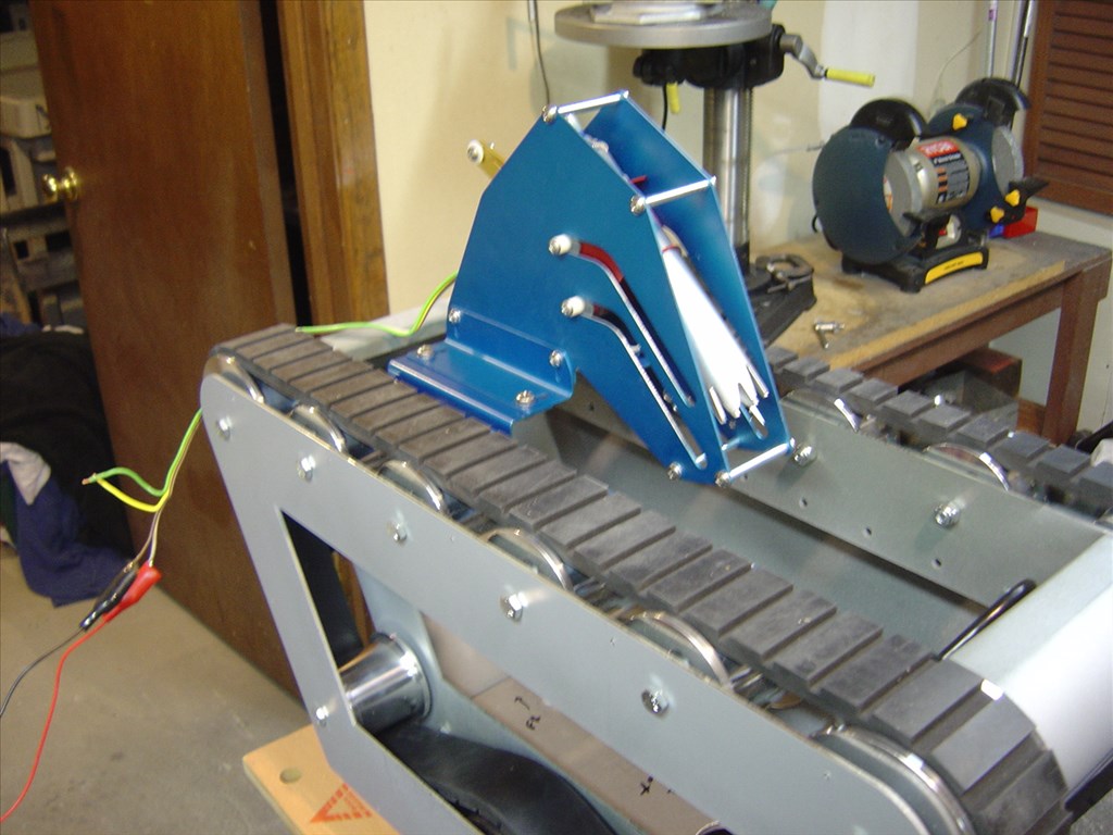
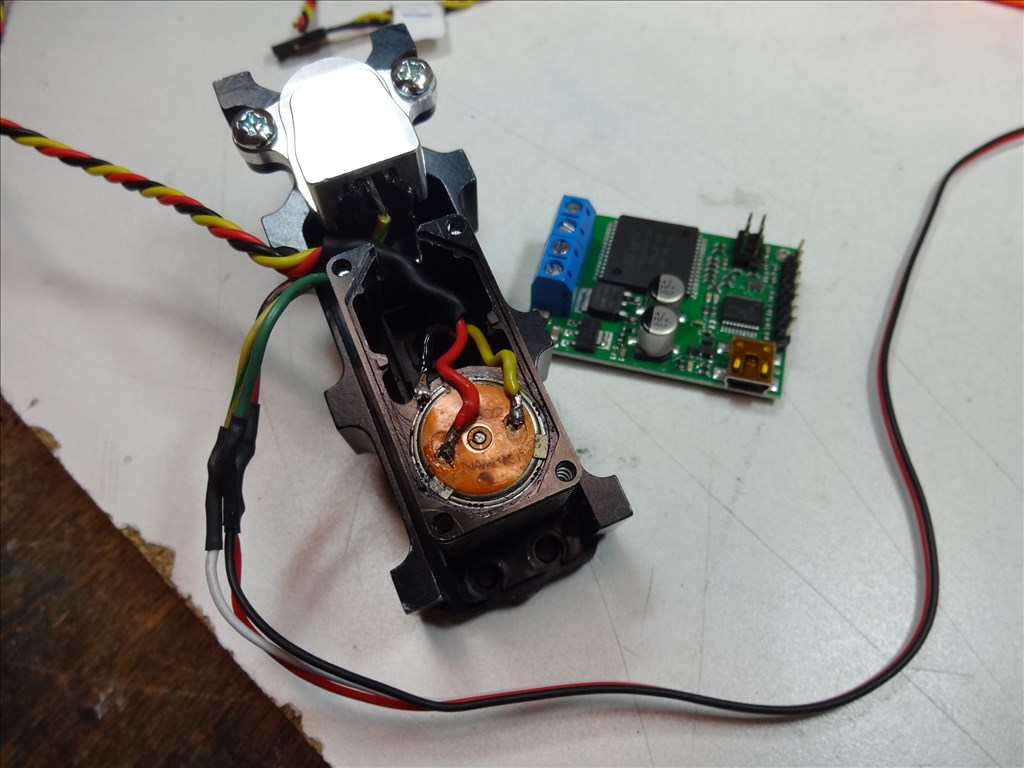
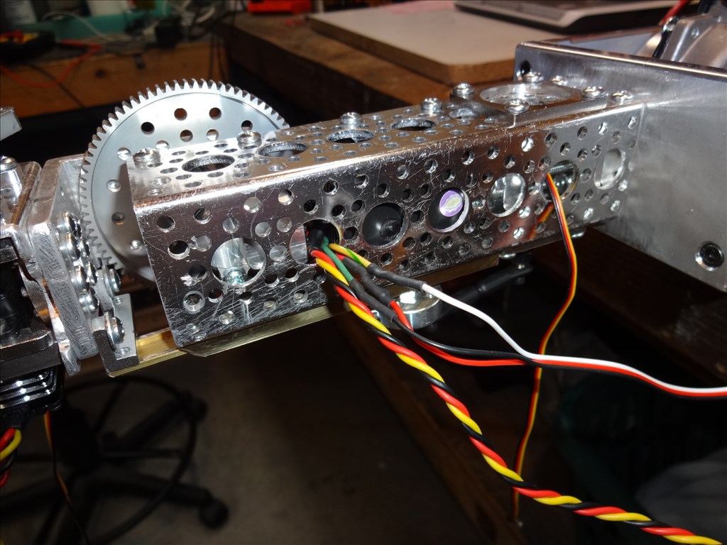
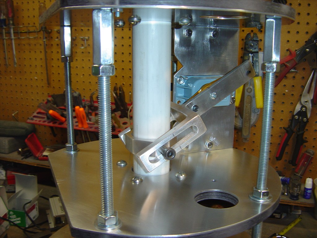
I'm going to have to use the DC windshield wiper motor for the elbow motor because I cant get my servo gearboxes to run in tandem at the same speed. I tried everything but no go. I'll use these gearbox servos for the lifting joint of the wrist. Since it will be closer to the end of the extended arm my test show it will have no problem lifting the needed load at a good speed. I've made a real cool motor mount that fits great. See pics below.
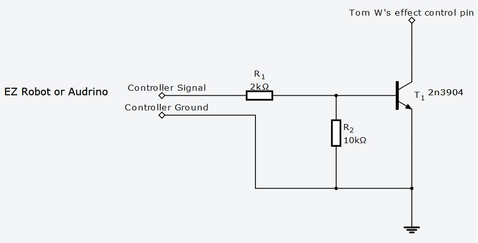
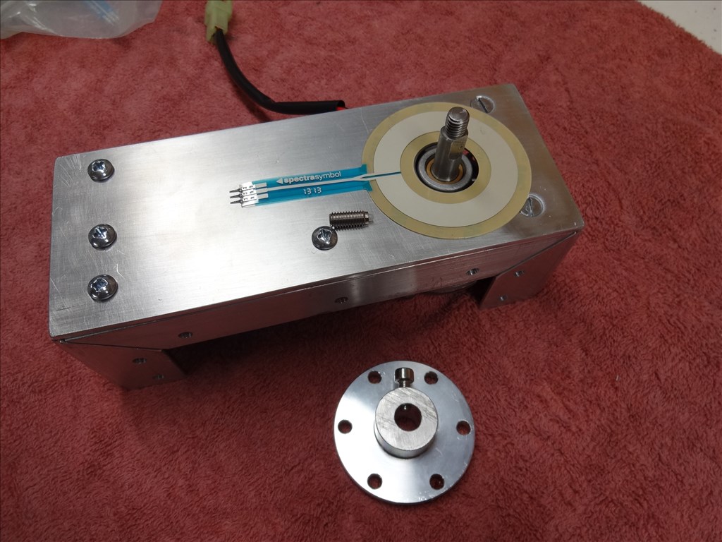
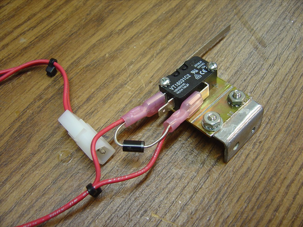
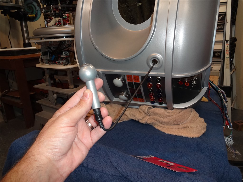
For speed and position feedback on the DC elbow motor I'll try using a Softpot Rotary Potentiometer. These are very thin variable potentiometers. By pressing down on various parts of the rotary dial, the resistance linearly changes from 100Ohms to 10,000Ohms.
SoftPot
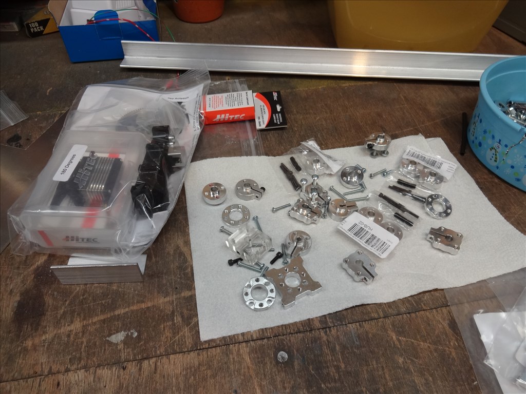
I'll be using Actobotics parts from ServoCity to connect everything and for the arm structure.
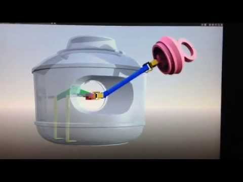
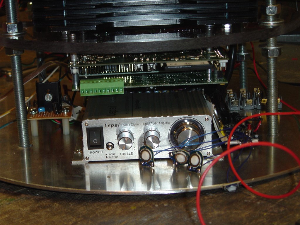
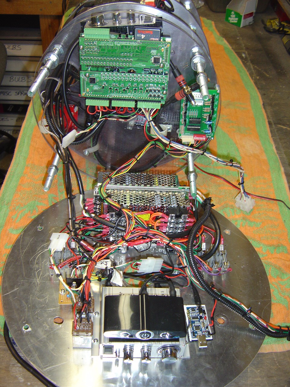
Arm guts
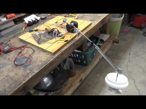
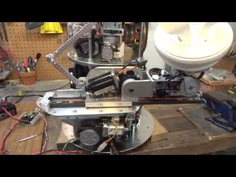
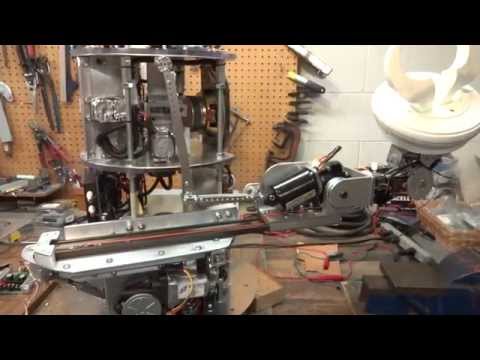
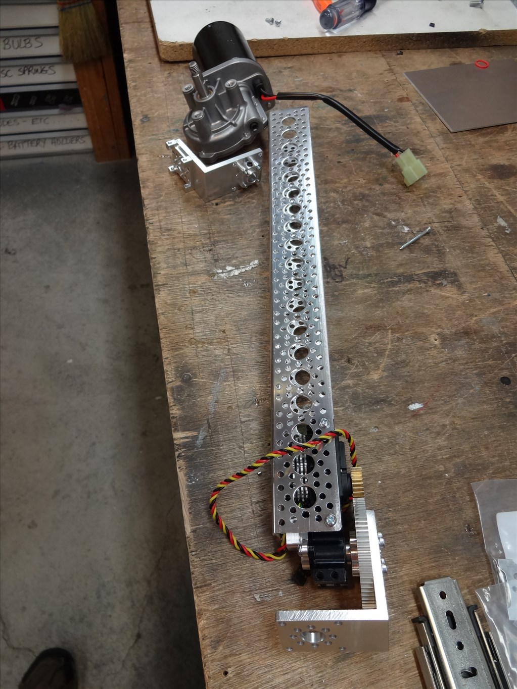
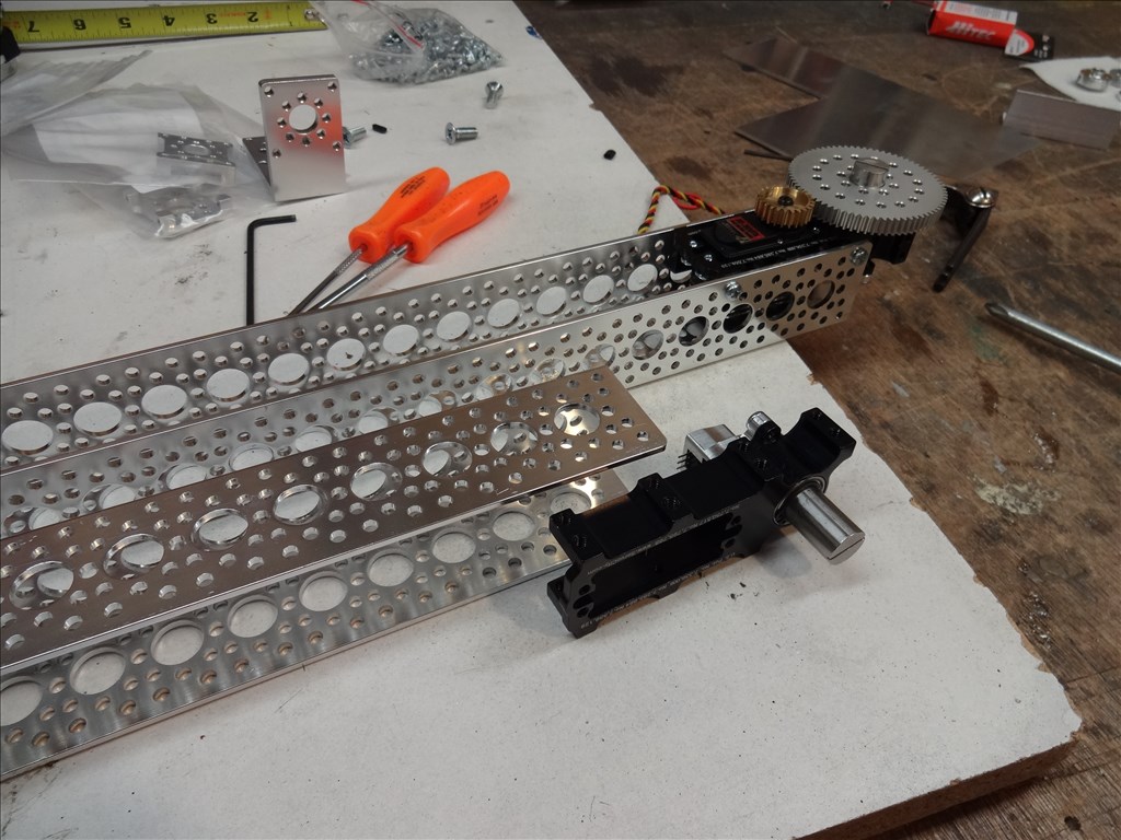
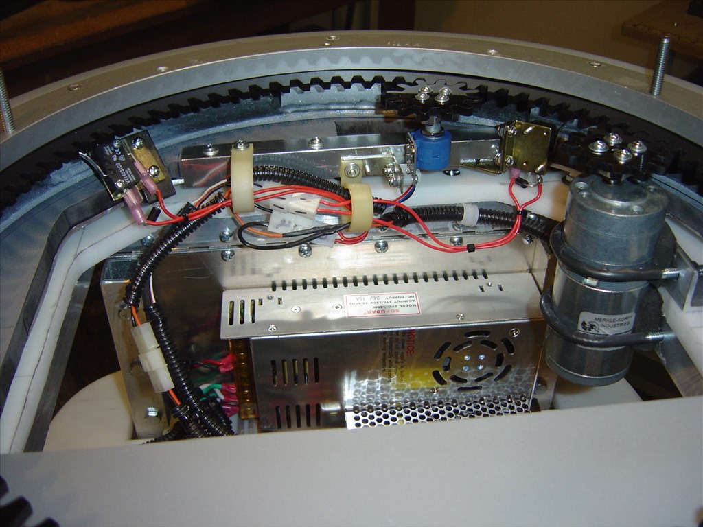
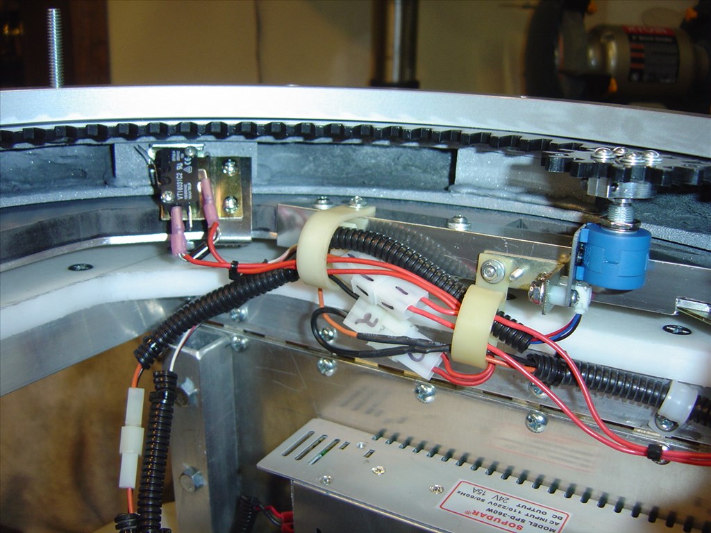
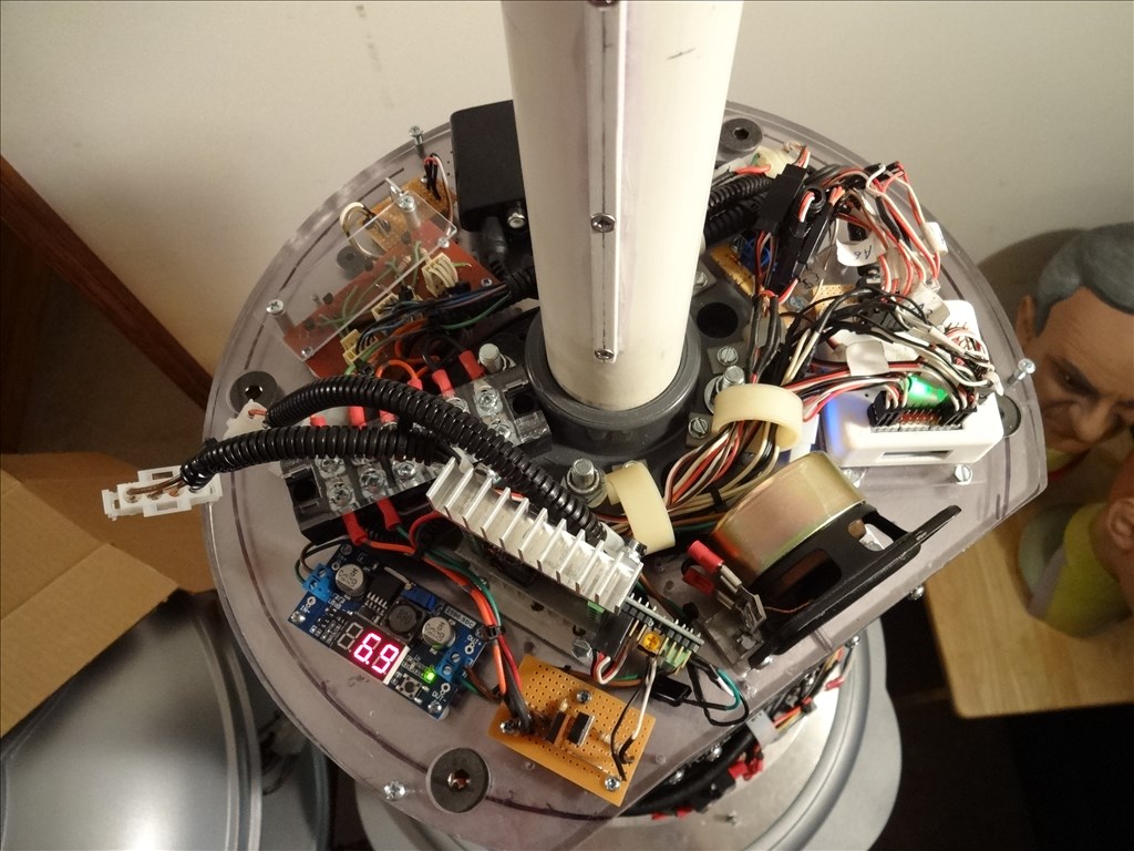
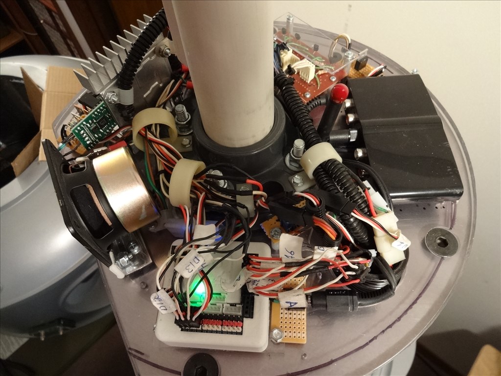
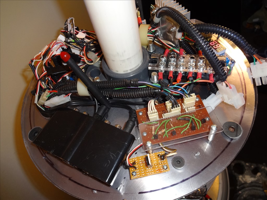
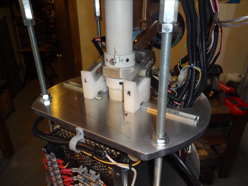
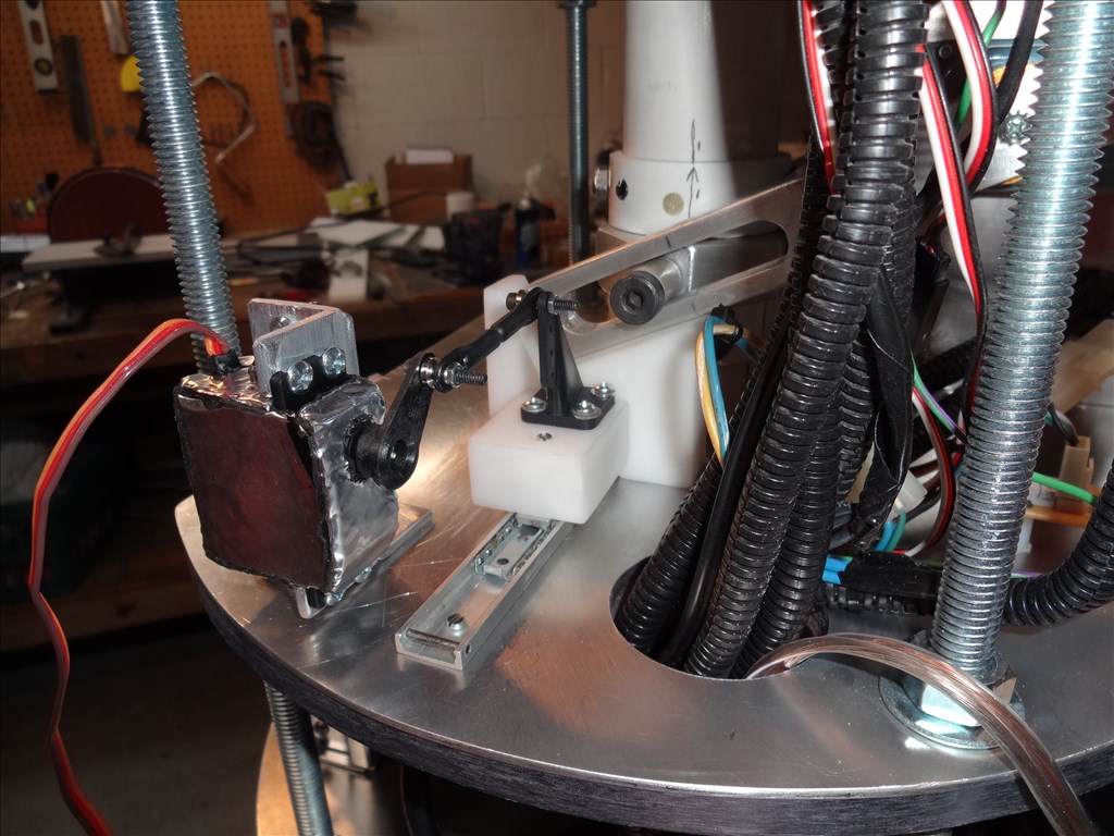
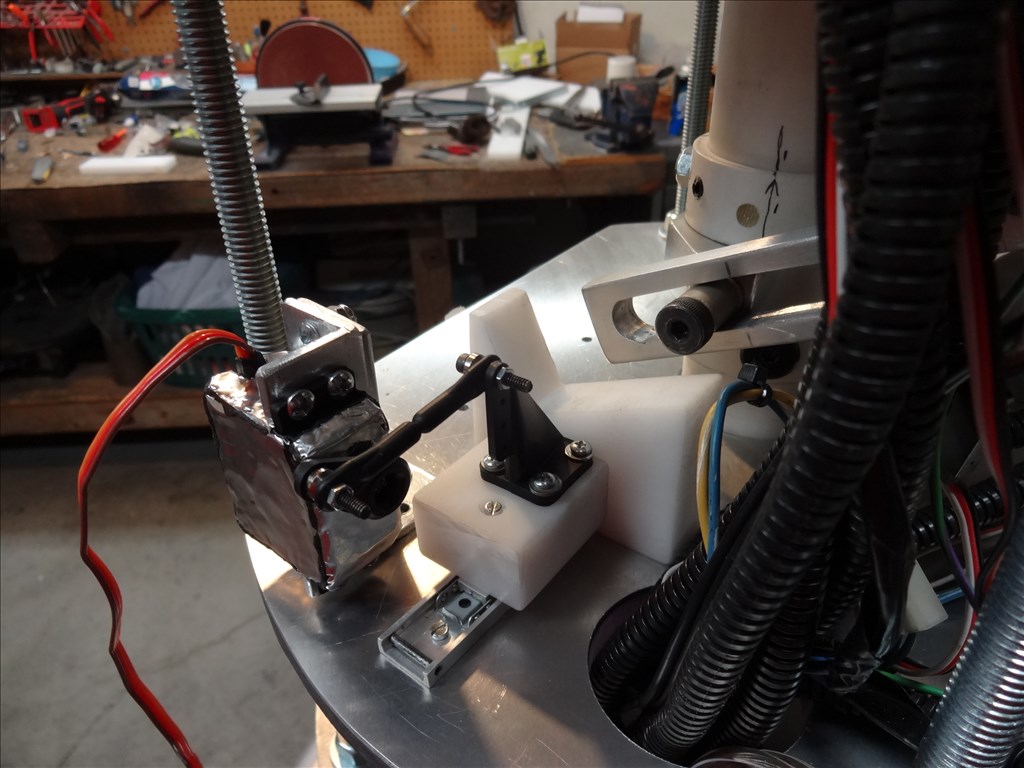
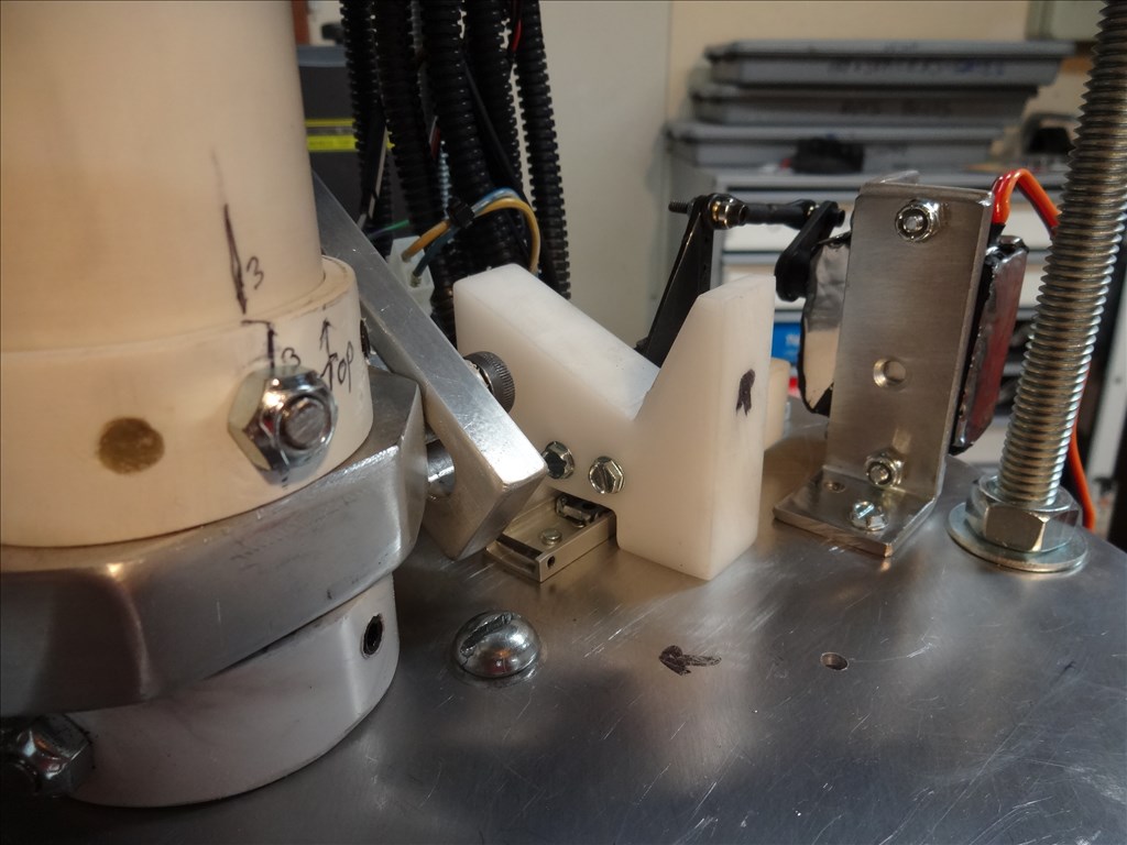
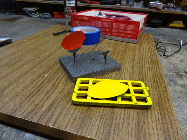
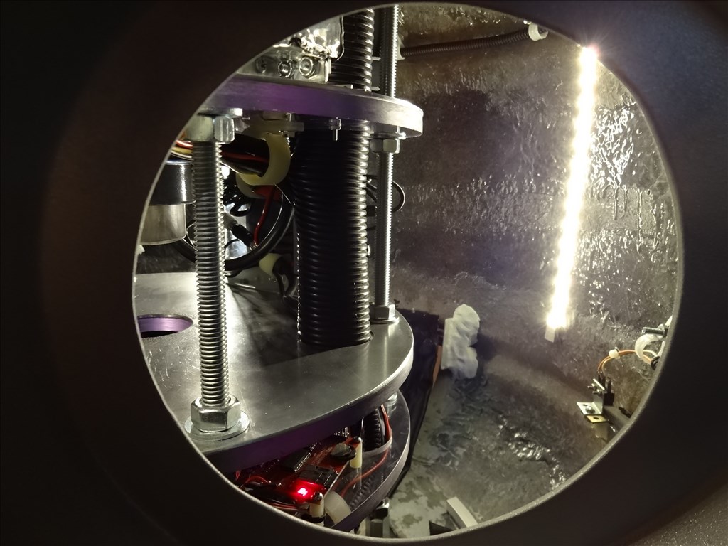
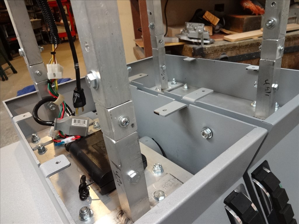
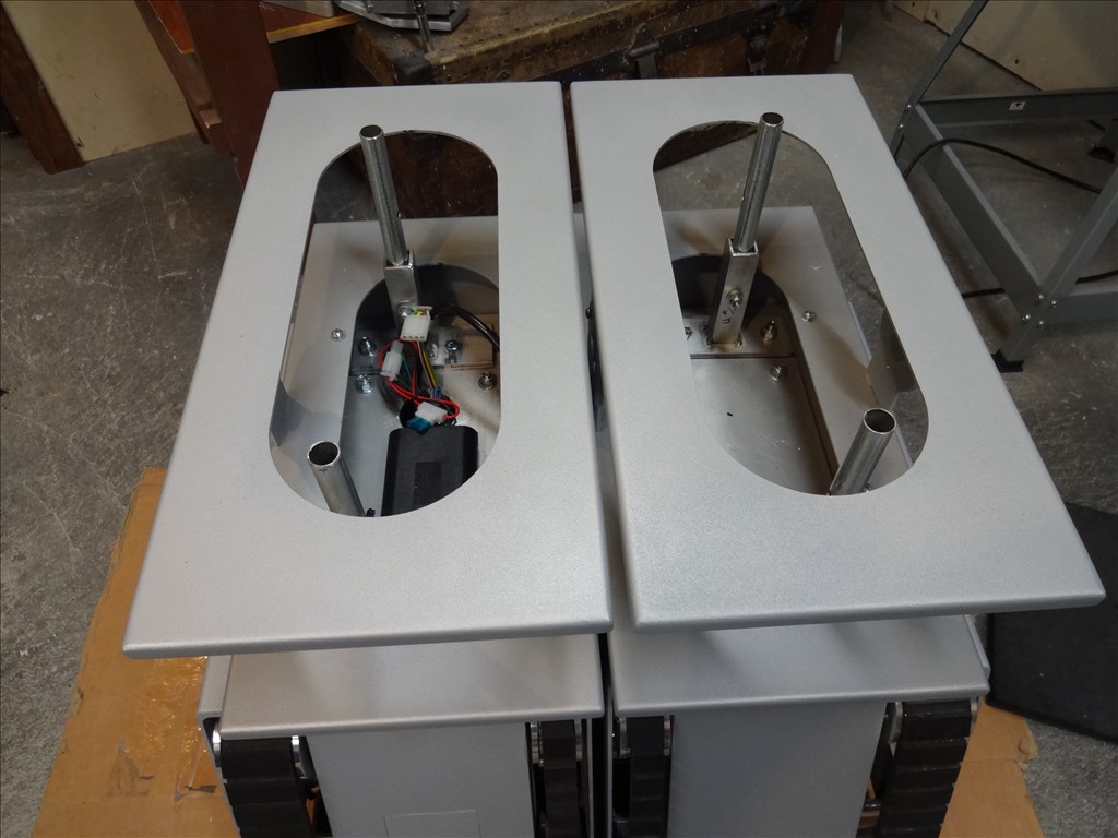
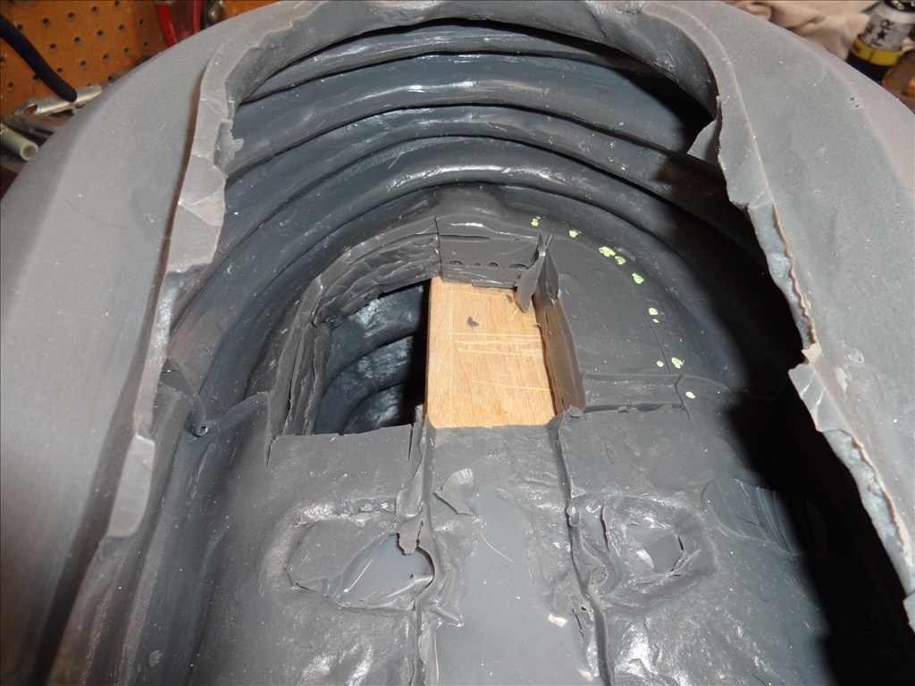
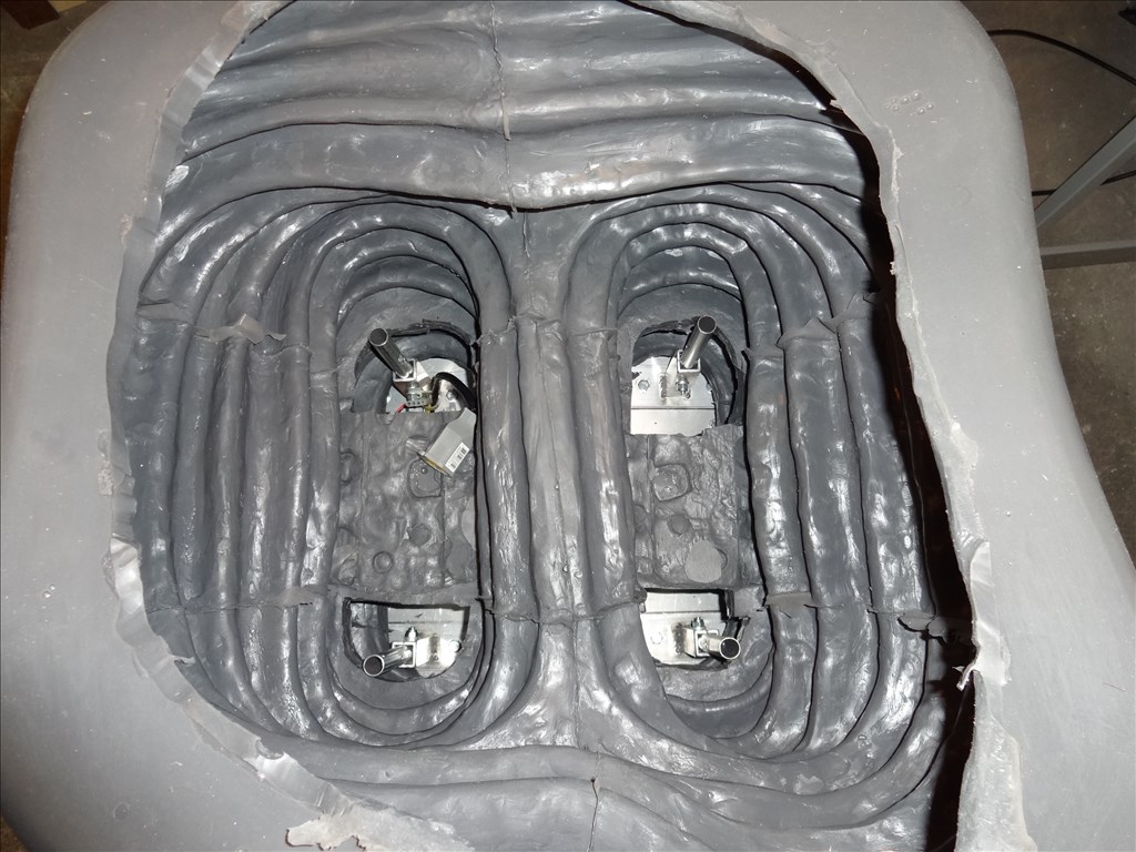
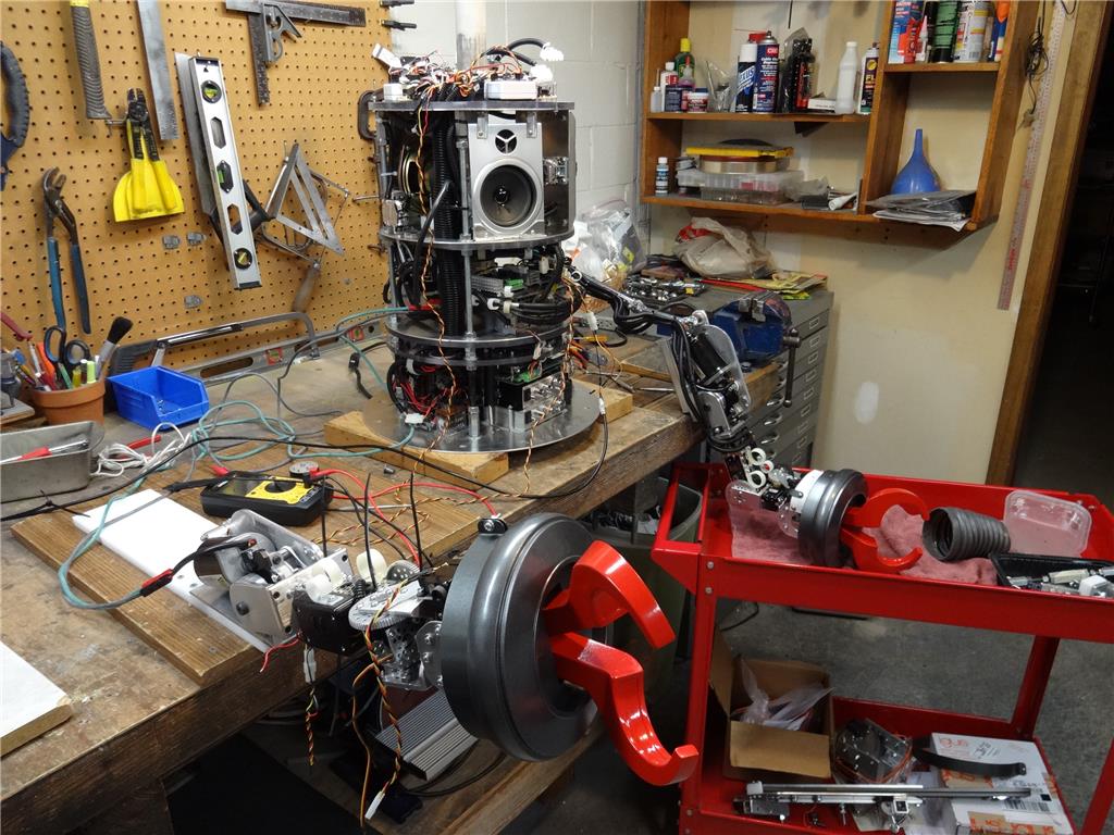
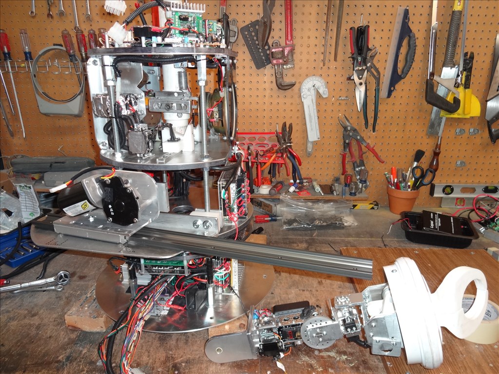
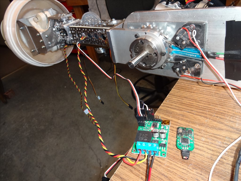
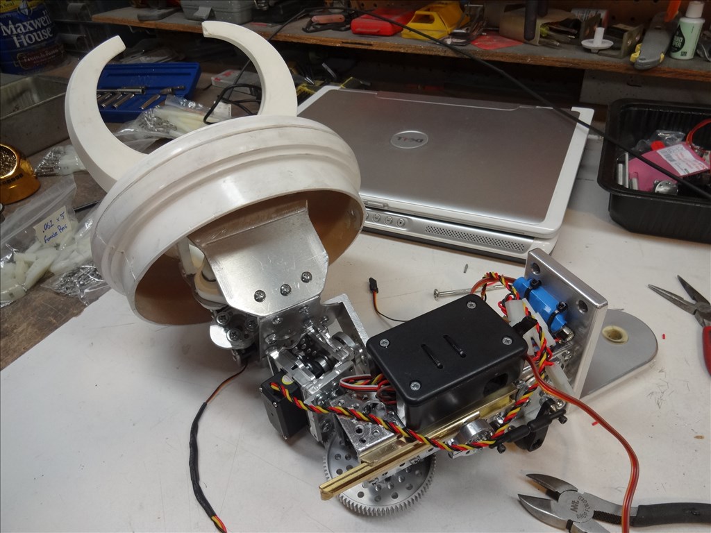
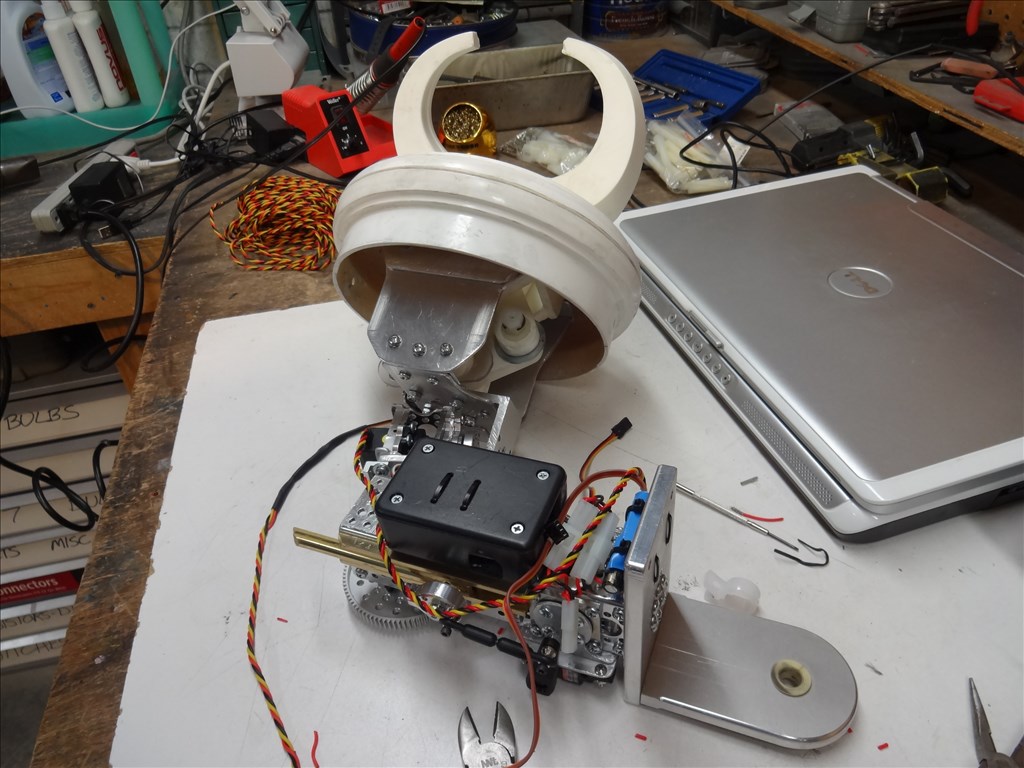
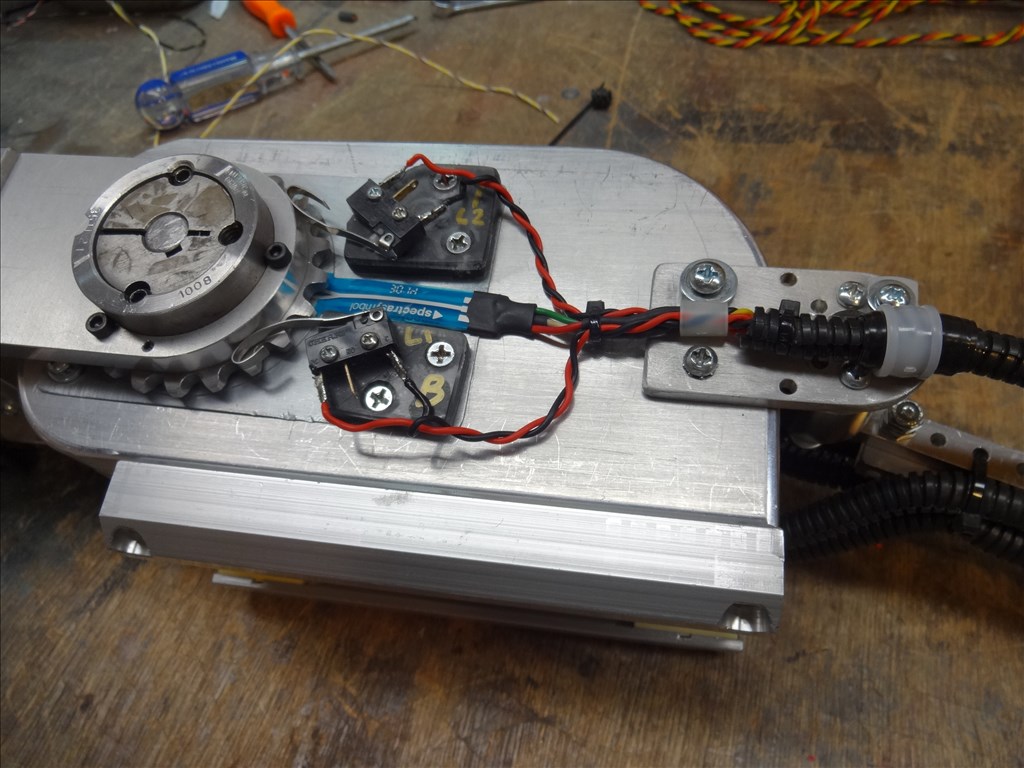
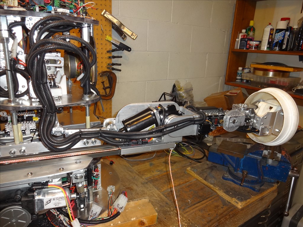
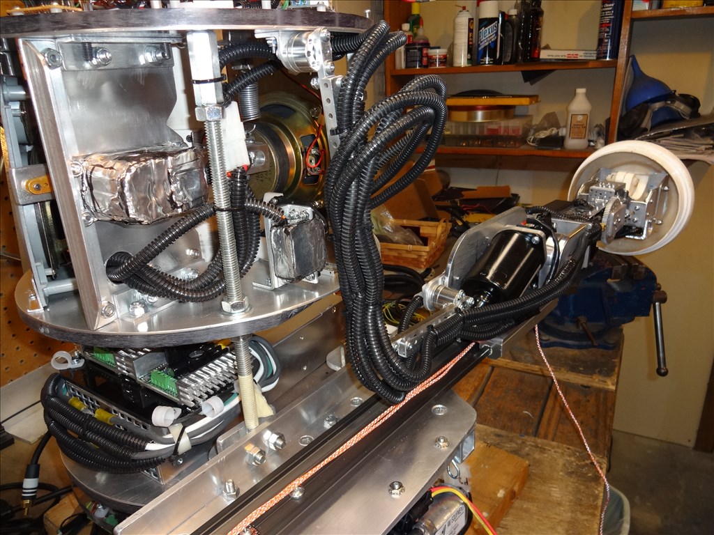
Here's a few pics of what I have so far:
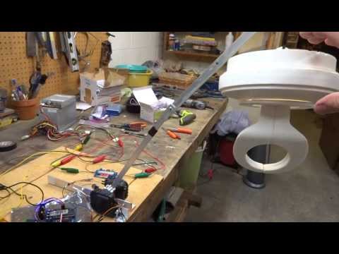
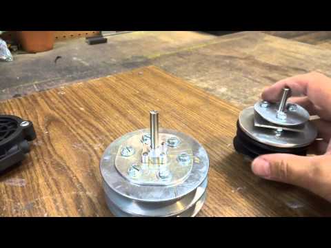
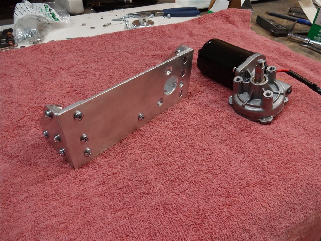
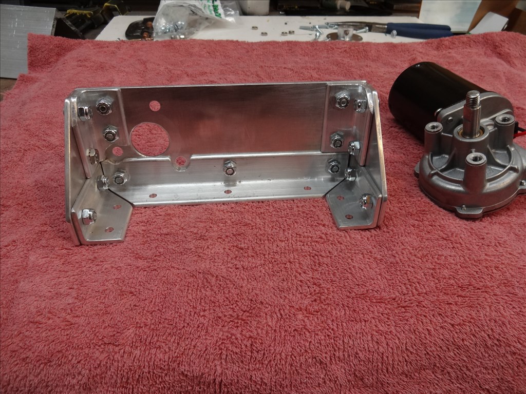
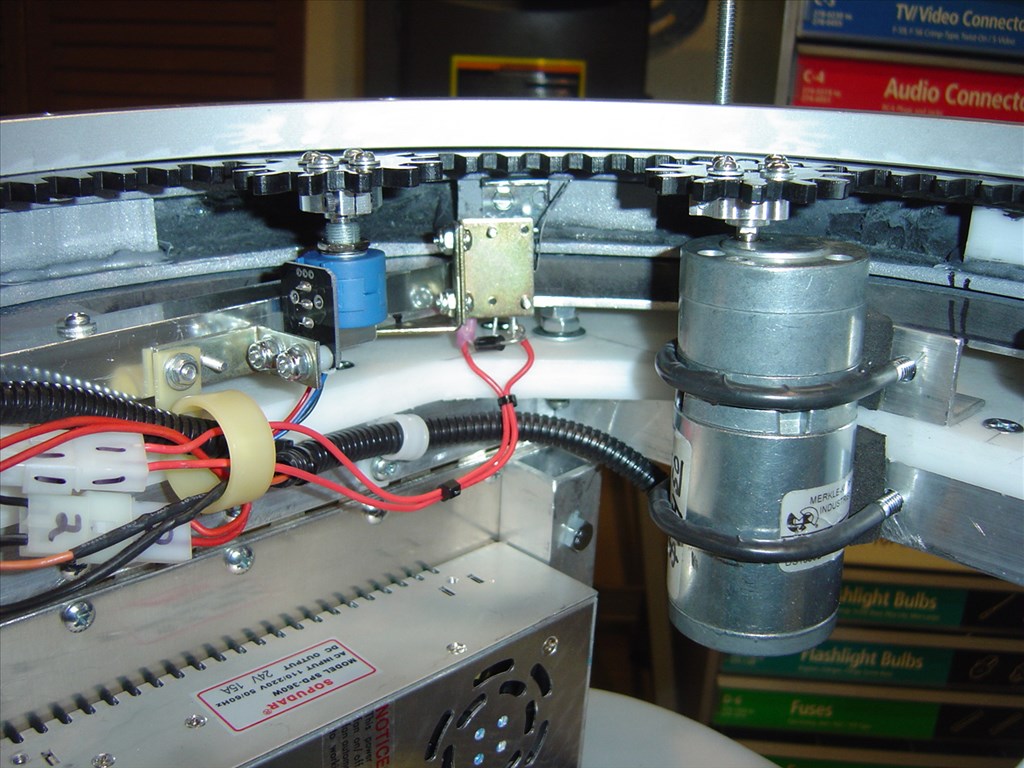
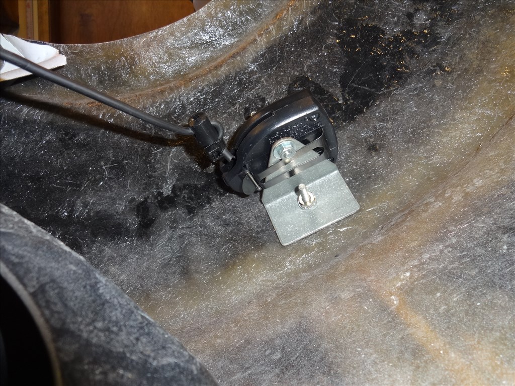
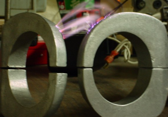
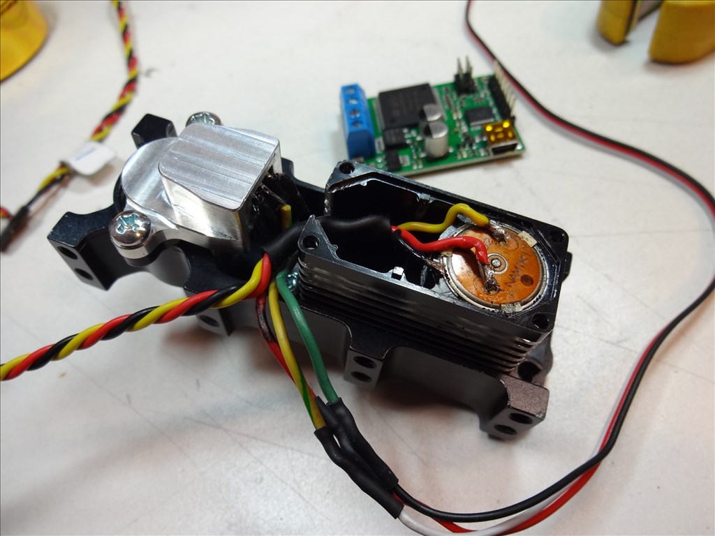
Here's a few pics of the motor mount I built to hold the DC elbow motor:
And here's the SoftPot:
Dave, that looks like way more fun than the erector set 600 piece kit.
Dave, those are the exact same motors I used on Questor's drive train. They are really strong. I also had tried these for the elbow joint on my large robot Magnus. However, the weight of the forearm was too heavy and when I powered the motor down the arm would droop down due to the weight. But now that you have experience with the Kangaroo and Sabertooth combo maybe you can get it to hold position. Just hope it does not draw too much current while maintaining position.
I am very interested in your progress with this.
@Doc, Erector sets were never this expensive or this much fun!
@Rex, Glad you're so interested. Thanks. I also noticed that this motor won't hold it's position when powered down even though it's a worm gear motor. With the Kangaroo x2 / SaberTooth 2x12 that shouldn't be much of an issue. The Roo makes the DC motor hold like a servo till it gets a Release or Power Down command. As far as current; Im sure I'll be able to beef up any part of my power grid if needed.
Any updates on your B9 arms?
I built a working robot using an Erector set and some electric motors hooked to relays and photo resisters. The robot searched for light and then followed the light. This was before people had micro computers to use in robots.
Hi McSdaver, Thanks for the interest. Sorry it took so long to answer. Busy, busy, busy.
Yes, actually I've been steady working on the arms when I find some extra time here and there.
I do have a design that I have high hopes for that I actually haven't gotten to "work" the way I want just yet. I've been building prototype designs and finding what works and what doesn't. This has been a painfully slow and somewhat expensive process.
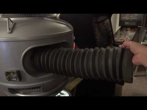
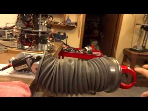
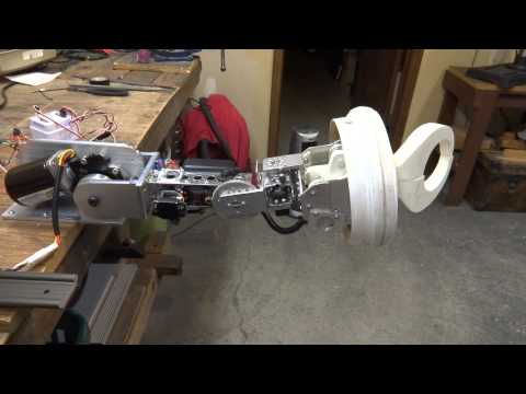
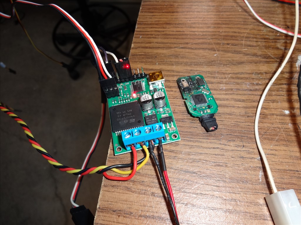
I finally had success with what I thought was my final design as I had my shoulder DC motor working nicely. I want it to lift up to seven pounds at a length at about 2 feet. My setup included a 12 vdc AME wormgear motor powered with a 12v/12 amp power supply controlled through a 2x12 Sabertooth and Kangaroo x2, using a flat SoftPot for feedback and being controlled with EZB V4 through the Uart port.
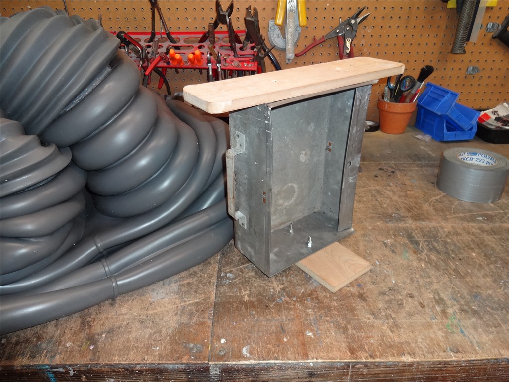
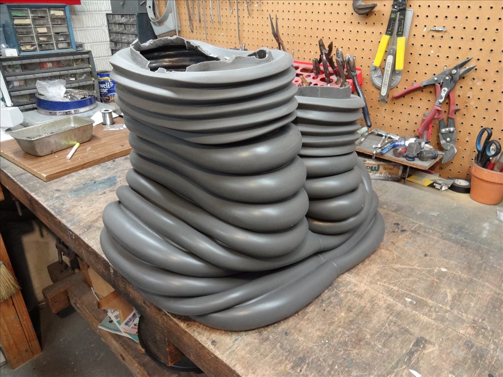
I was able to get a successful autotune with the Kangaroo/Sabertooth motor driver and was able to lift about 80% of my wanted weight. Then when I added the final rubber outer skin of the arm and a little ballast weight for overhead wiggle room but my sabertooth/Roo started to have power brownouts. Damm!
I reweighed everything and plugged this and my measurements into a neat little Robot Arm Calculator I found on the Society Of Robots web site. I found I was over the torque my 12 amp setup would be able to handle. In fact the motor I wanted to use stalls at 93 Lbs per inch and will pull 30 amps when this happens. The calculator says I need a motor capable of lifting 118 lbs per inch. Damm! Back to the drawing board. I needed to find a motor capable of lifting more than 118 lbs per inch, more power and another motor controller capable of handling all this.
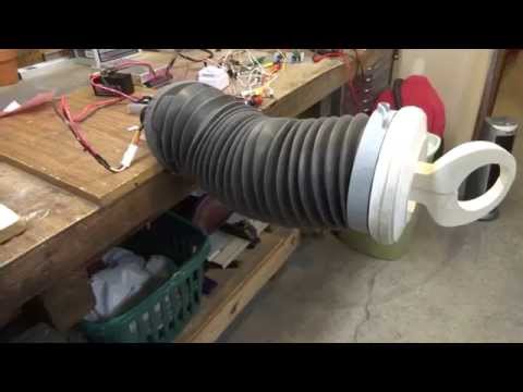
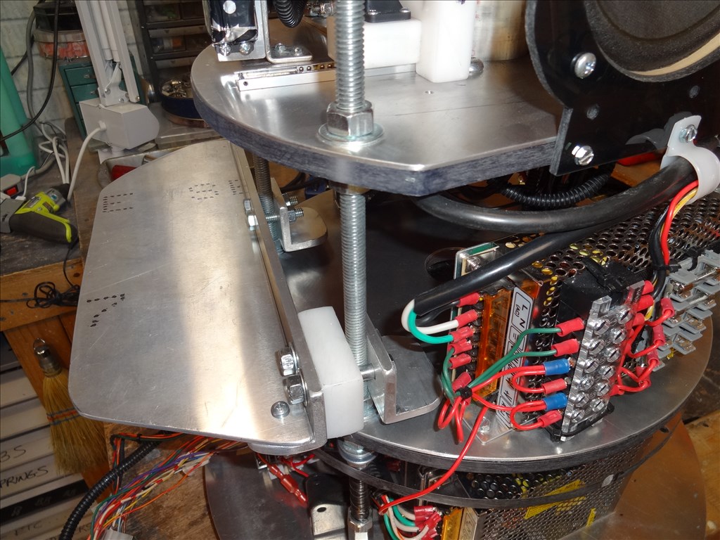
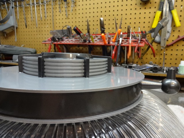
What I came up with is an AME-226-series 12V Utility Gearhead Motor at The Robot Marketplace. It will handle my load and to lift my max overhead wright of 118 lbs per inch. When doing this it will be pulling about 30 amps. In theory to get this to play nice together I also had to get a 12vdc-30 amp power supply and a Sabertooth 2x32 to handle this little monster. The only thing is that this new motor is a little bigger than my old motor so I just now started making a new motor mount for it.
Here's the stuff:
AME-226 Motor
SoftPot
Sabertooth 2x32
That's where I am now. I can't test run this new setup till I get everything rebuilt and mounted. Sadly I don't see that happening for at least two more weeks considering my "real life" commitments. tired
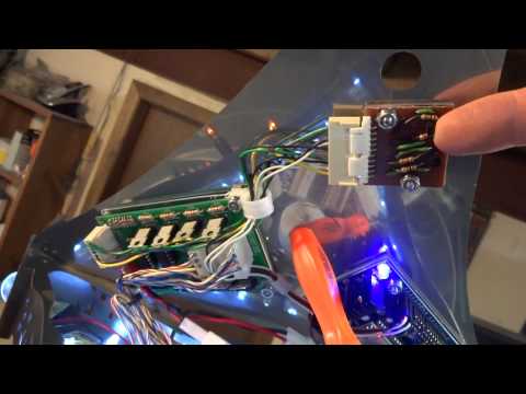
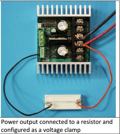
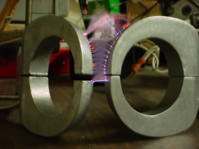
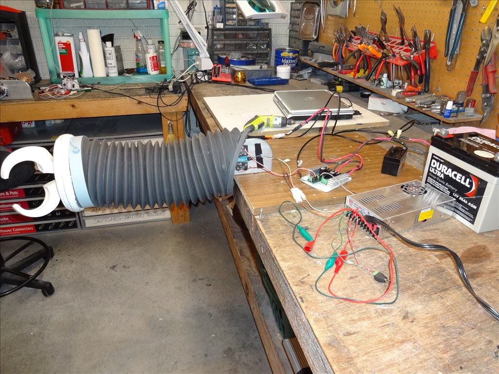
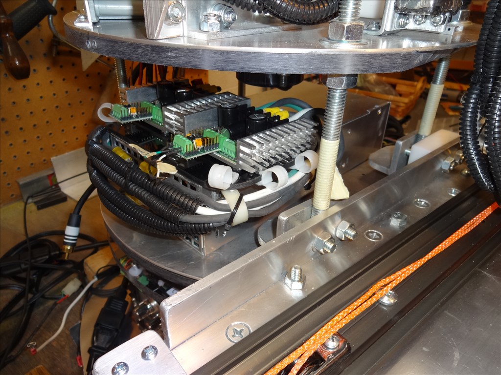
One great thing about this upgrade; The Sabertooth 2x32 has an extra set of power and control ports. I can use a power resistor across the power feed and the extra power output ports on each channel as a voltage clamp and I don't need a battery and the extra circuitry to dump the regen power because I'm using a power supply instead of a battery. This is great as I'll be able to simplify my whole setup! Here's how it looks:
I wonder if you had room to add a threaded rod to the end of the motor shaft with a nut on the shaft to used to increase torque. Grease the rod and connect the load to the nut. This would gear down the motor even more. This way the motor could handle the weight of the arm and then some.
Hi Dave; Amazing how much time is gobbled up with trial and error. Glad to hear its moving forward. I'm using a compound drawer slide, pulley system and cable to extend the arm and retract it. Finally proved a working prototype, now just have to finalize it and build it times 2. Rough part is coming home, it's already dark out, and feels like midnight. Not easy to go down to the workshop.
Regards, Don