

Well, I've been at a standstill on this guy for months due to parts issues and time constraints.
Got the parts, got the time. So, with no further adieu...
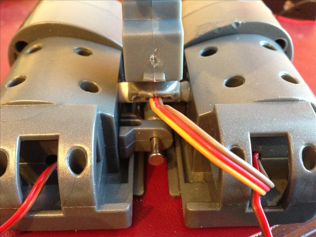
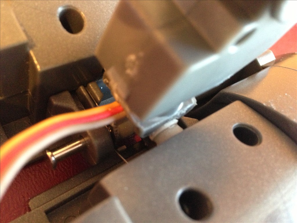
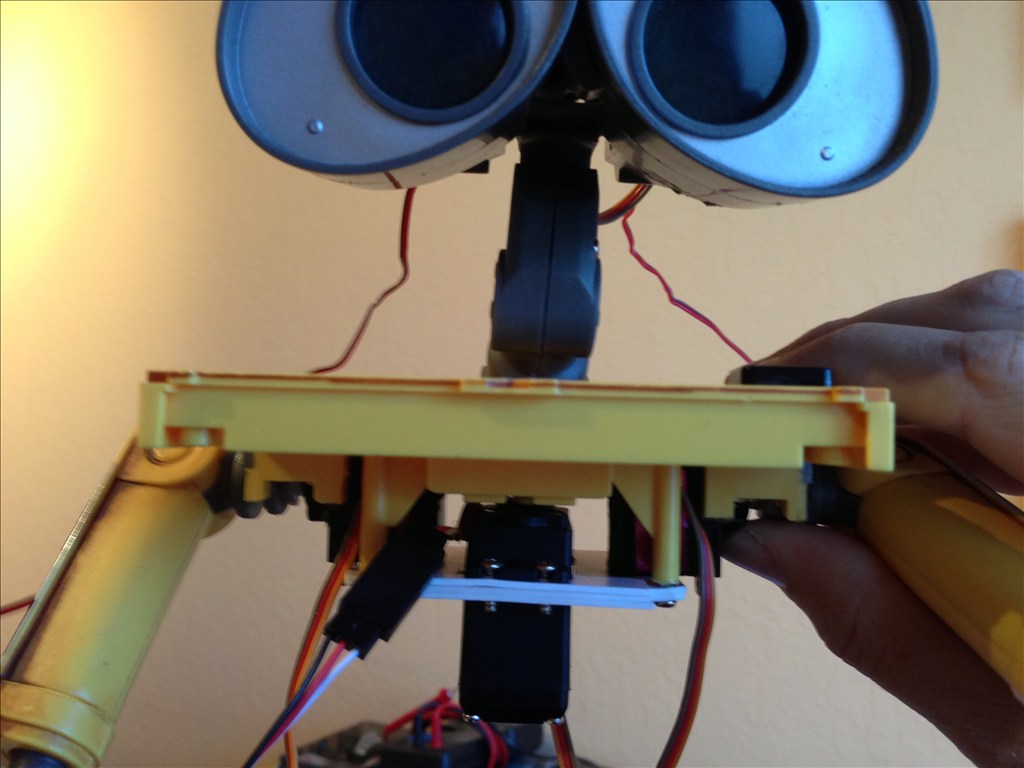
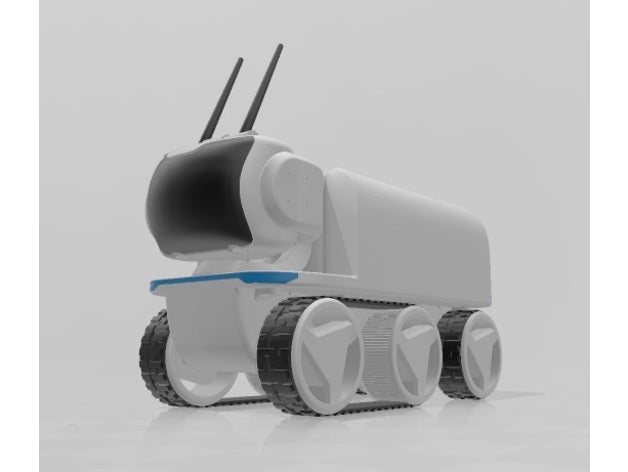
Image #1 shows the aftermath of converting the head to being able to nod. I thought long and hard about how I could keep the original eye movement mechanism, but after long debate (and lack of a good solution), I went ahead and removed most of the stock material and, using a micro 9 oz. metal gear servo, put a tube across the eyes and attached it to the top of the neck (modified to basically be a saddle for the tube). The servo is mounted in the left eye socket, and fits quite well.
OK, that's it for this post. Next up is audio, and programming.
By cyberdude
— Last update
Other robots from Synthiam community
Jstarne1's Calling All 3D Printers! Get The Stls While They...
LEVi Rover 3D files assembled and ready to print, with model cuts for smaller beds and community tips for printing and...
Pirumpi's Pringles Robot
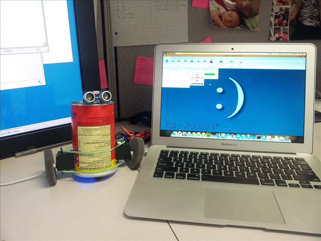
EZ-B enables quick creation of a Pringle Robot during launch time, showcasing fast, easy robot building.
Steve's 2 Ft Biped Walking(Shuffle) Robot
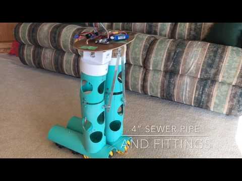
Omni-wheel robot build: overcome turning and weight distribution with center-pivot knees/hips; PVC construction and...

Looking really good!
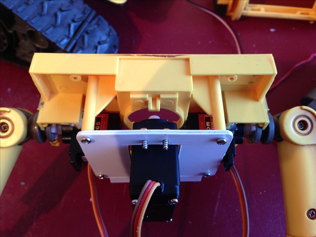
Looking good. Love the mounting plate for head rotation.
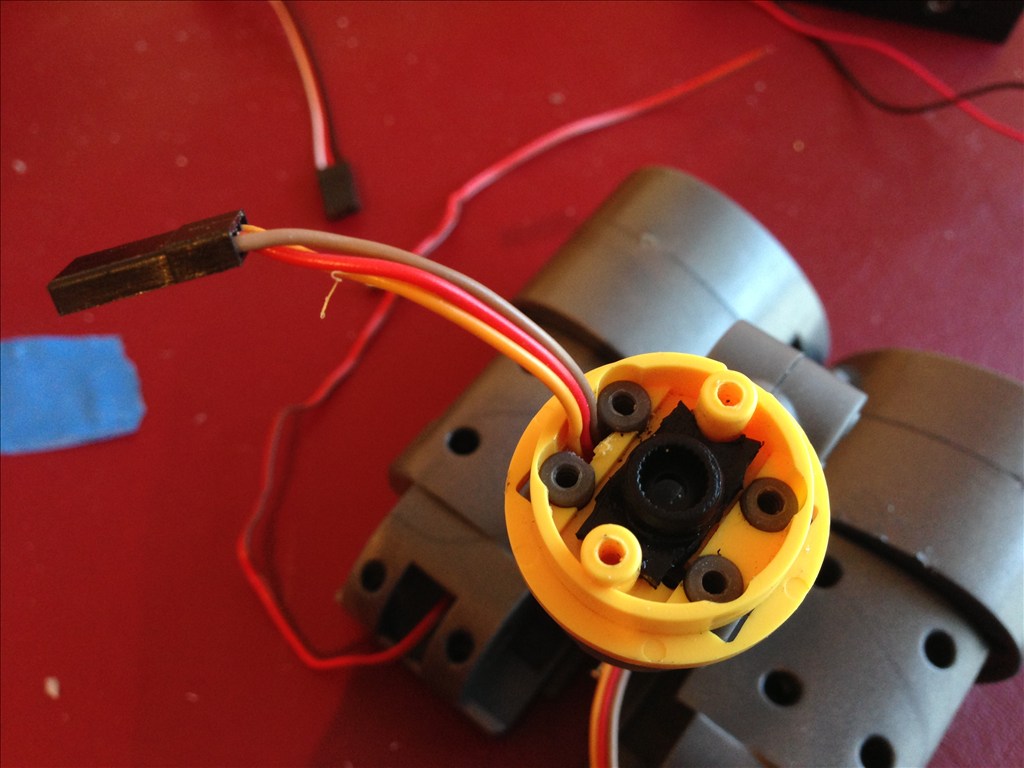
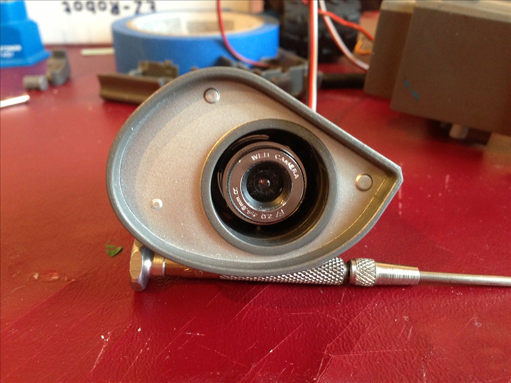
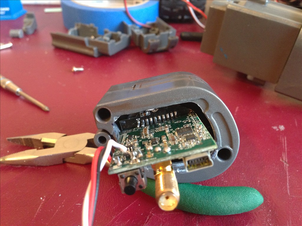
I removed the antenna mount, USB connector and switch from the camera. Made it easier to clam the eye all back together. I extended the antenna leads and relocated the antenna to Wall-E's body side.
@lumpy, good idea. Since this is my first foray, I figured I'd get him all functional, and play, then decide next steps.
I hear ya.
Antenna connector if you need new.
www.sparkfun.com/products/593
Soldered onto this
www.sparkfun.com/products/8808
Cheers,
Wow! All the electronics within the enclosure look very intact and organized. Well done!
Thank you. The battery situation is challenging because the drain is quite high and the 6 cells rain quickly.
I'll post finishing shots later in the week.
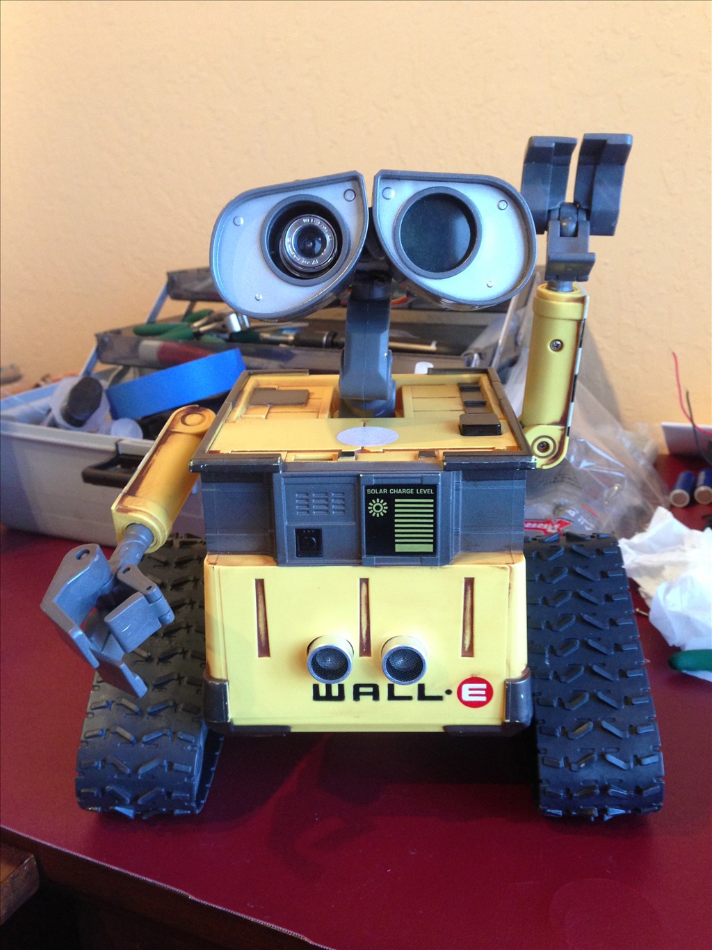
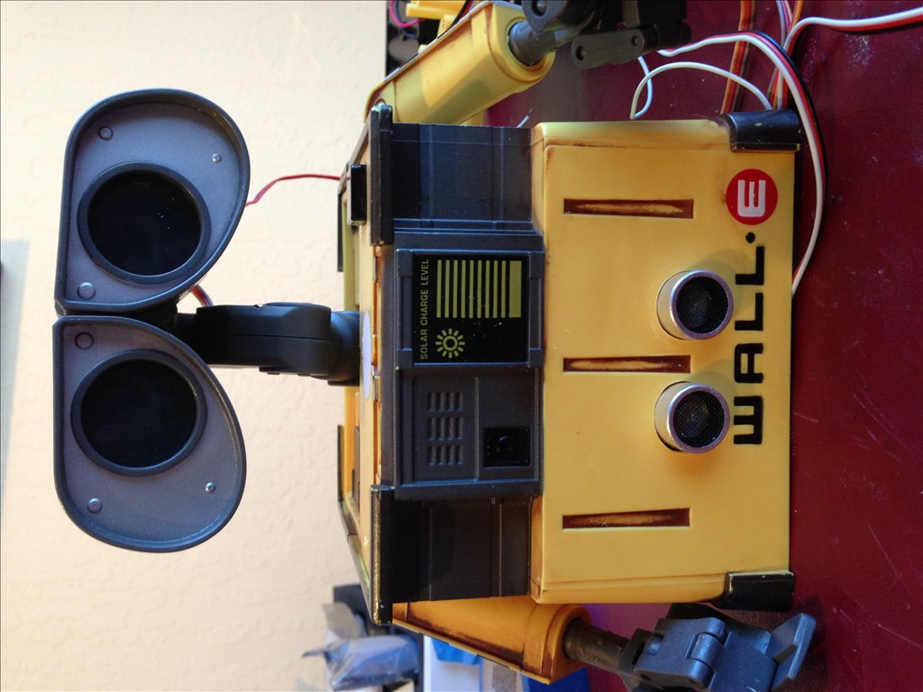
OK, So Wall-E is put back together (mostly). I stuck the supplied battery pack into the inner side edge of the body, but it REALLY doesn't last very long, so I have him tethered to a 6v Gell Cell for development purposes.
Here are some picks:
Wall-E is waving!
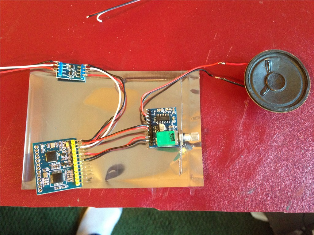
Here's his back. Yes, the board does fit in his back and I am able to close him up...but that rarely happens...
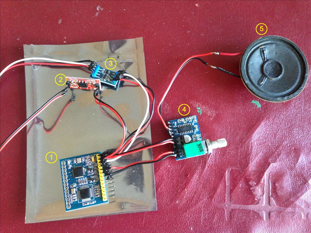
And here's one of the reasons why. I'm adding a new MP3 board. Damnedest thing happen to the first one I installed. Worked fine, but then lost serial functionality. The board initializes, but after playing the first sound automatically on init, I have no control. MDFly of course doesn't stock it anymore, so I got a different model from them. This one works the same way, but requires TWO voltage sources...One for the signal level line, the other to power the board. SO I took the little battery from the wireless camera (3.3 volts) and jury rigged it to work. Now I'm waiting for a hand full of 3.3v step down converters from China. I'll be able to put one in line with the 5v ext. power of the EZB and run it to the MP3 board (hopefully), otherwise, I have to run it from a second terminal set off the battery.
This is a very tidy build. I like how you have thought things out.