


Well, I've been at a standstill on this guy for months due to parts issues and time constraints.
Got the parts, got the time. So, with no further adieu...
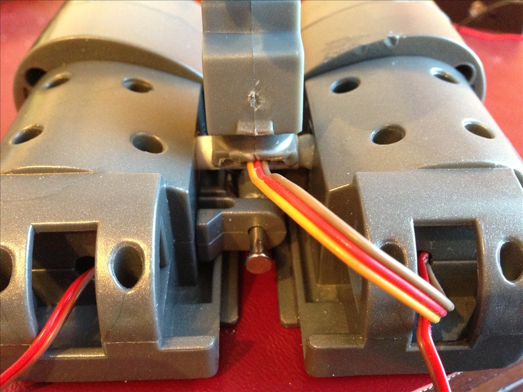
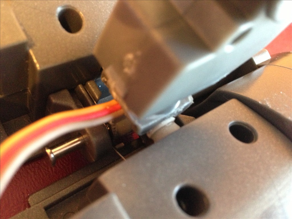
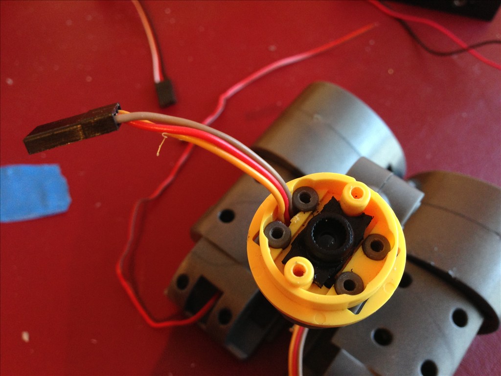
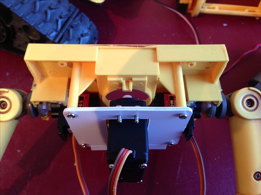
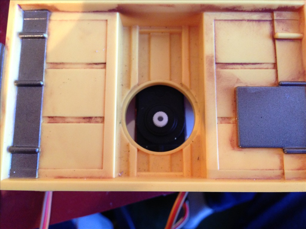
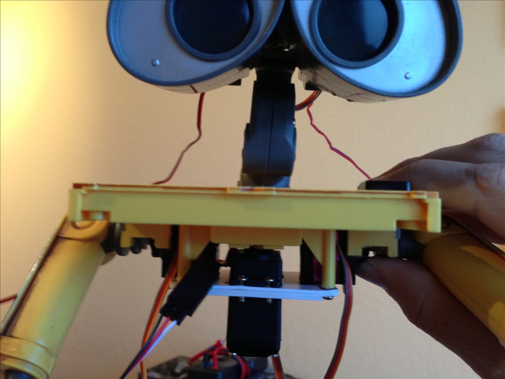
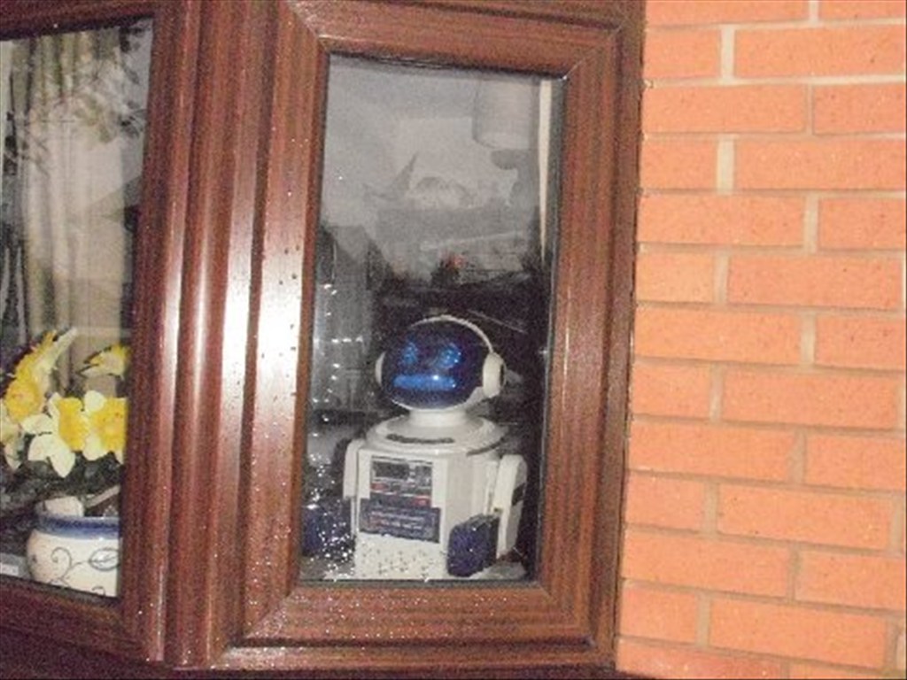
Image #1 shows the aftermath of converting the head to being able to nod. I thought long and hard about how I could keep the original eye movement mechanism, but after long debate (and lack of a good solution), I went ahead and removed most of the stock material and, using a micro 9 oz. metal gear servo, put a tube across the eyes and attached it to the top of the neck (modified to basically be a saddle for the tube). The servo is mounted in the left eye socket, and fits quite well.
OK, that's it for this post. Next up is audio, and programming.
By cyberdude
— Last update
Discover more robots
Rich's Project Hearoid.
Refurbish Hearoid with EZ-B: autonomous 24/7 self-charging robot with pan/tilt camera, image tracking, servos,...
Mcjeff0125's Ez Rover Mark I
Control a Brookstone Rover with EZ-B using ARC software: removable EZ-B pods, battery/speaker mounts, Lego platform,...
Ezang's Two Projects From The Past - Re-Mixed
Detect faces or absence of faces and play robot sound files when red is detected in Justin's remixed projects.

Here's the first "real" script I wrote for him. If he gets boxed in, he checks around him to see if there's a way out. If not, he'll back up.
Since its really a test condition, its meant to be called as a routine from a larger general script, like a "wonder around" type of script.
I'll post the code in examples as "Boxed in".
*Disclaimer: I am NOT a programmer, so I make no claims to the cleanliness, clarity, buginess, etc. Use at your own risk.
Of course, you're welcome to improve it and tell me about it
Awesome very inspiring cyberdude and Thanks for all the great pics!
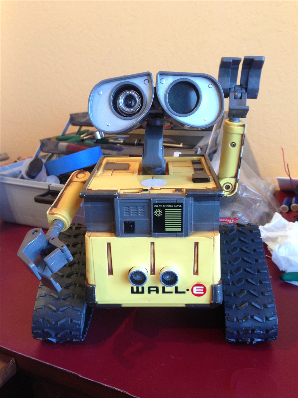
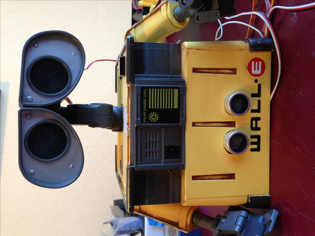
Wow, that wall-e actually looks smaller than the U-command, i noticed you say its based off of it. Can you tell me which Wall-e toy that was? Or if it is the U-command?
This is the U-Command model.
OK, as promised, here are some updates to the project...
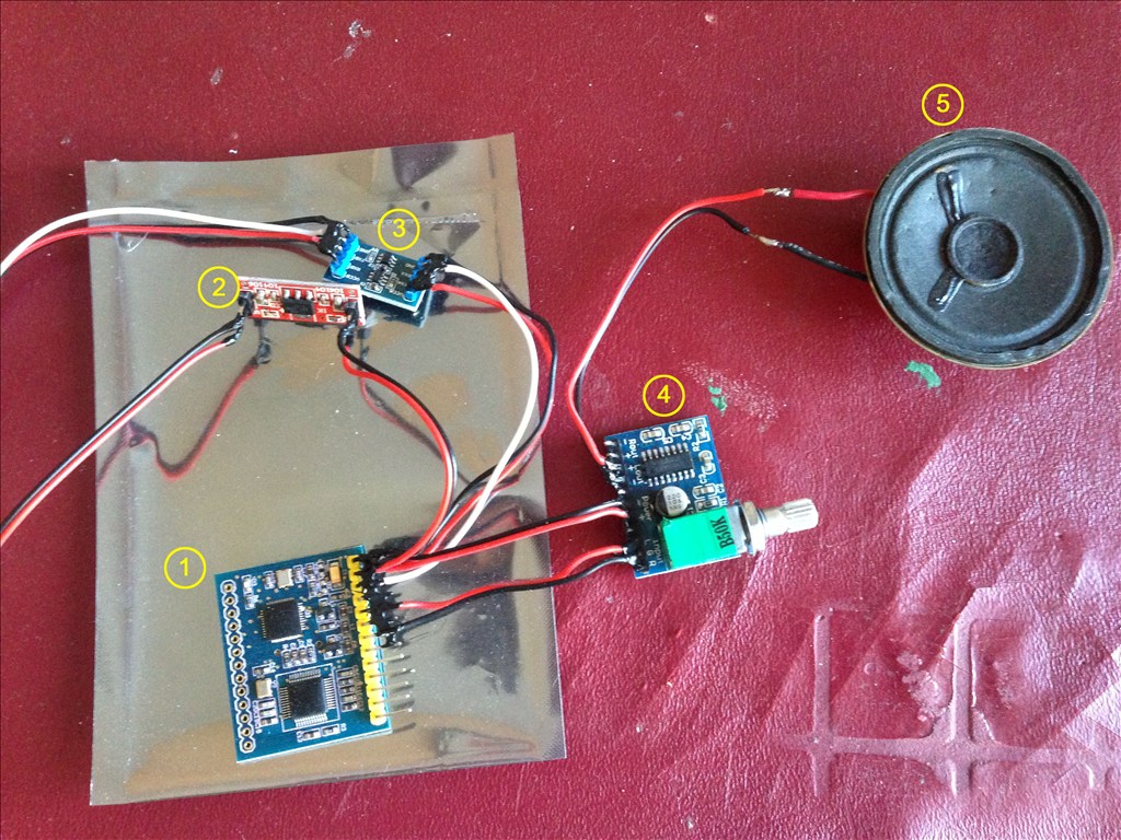
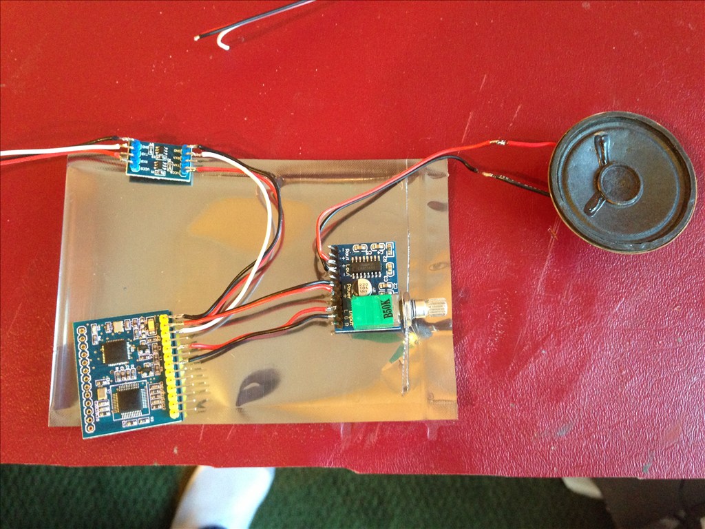
Okely Dokely, here's what we have...
This is the AU5032 from MDFly.
This is a 5v step down circuit that I picked up from eBay. (I have a few more if ya need one.) " AMS1117-3.3 DC/DC Step-Down Voltage Regulator Adapter Convertor W 3.3V Out"
This is also from MDFly: Logic Level Converter - 2.5v/3.3v/5v. I could have used two of these instead of the AMS1117 above, but this was $2.95 PLUS shipping from MDFly whereas the AMS1117 was $2.17 for FIVE INCLUDING SHIPPING!
Amplifier (the sound card is not amplified)
Speaker.
So the deal is that this particular sound card requires TWO 3.3v voltage inputs to function; one drives the comms signal, the other drives the circuit. I'm no EEE, so I have no idea why, I just know that I needed both.
All in all, it set me back something like $24 bucks not including the speaker and micro card (I had both laying around.)
Also, I should mention that one set of leads goes to a free port on the controller. the voltage-only leads go to the 5v out pins on the controller. I wasn't using them for anything else, so there ya go. It uses typical serial comms.
Very well explained, these contributions are appreciated, and a whole costs something like half the price of the trigger mp3 spankfun. Does that mean that the communication via ez-b from any port makes digital?
If I understand your question correctly, the answer is, the signal and signal voltage comes from and digital port. The second voltage can come from any port supplying 5v, but since there's a 5v for external power head, I used that for the second power feed.